EP2573312B1 - Schnurschloss - Google Patents
Schnurschloss Download PDFInfo
- Publication number
- EP2573312B1 EP2573312B1 EP20120181501 EP12181501A EP2573312B1 EP 2573312 B1 EP2573312 B1 EP 2573312B1 EP 20120181501 EP20120181501 EP 20120181501 EP 12181501 A EP12181501 A EP 12181501A EP 2573312 B1 EP2573312 B1 EP 2573312B1
- Authority
- EP
- European Patent Office
- Prior art keywords
- bearing
- cord
- axis
- shading
- cord lock
- Prior art date
- Legal status (The legal status is an assumption and is not a legal conclusion. Google has not performed a legal analysis and makes no representation as to the accuracy of the status listed.)
- Active
Links
Images

Classifications
-
- E—FIXED CONSTRUCTIONS
- E06—DOORS, WINDOWS, SHUTTERS, OR ROLLER BLINDS IN GENERAL; LADDERS
- E06B—FIXED OR MOVABLE CLOSURES FOR OPENINGS IN BUILDINGS, VEHICLES, FENCES OR LIKE ENCLOSURES IN GENERAL, e.g. DOORS, WINDOWS, BLINDS, GATES
- E06B9/00—Screening or protective devices for wall or similar openings, with or without operating or securing mechanisms; Closures of similar construction
- E06B9/24—Screens or other constructions affording protection against light, especially against sunshine; Similar screens for privacy or appearance; Slat blinds
- E06B9/26—Lamellar or like blinds, e.g. venetian blinds
- E06B9/28—Lamellar or like blinds, e.g. venetian blinds with horizontal lamellae, e.g. non-liftable
- E06B9/30—Lamellar or like blinds, e.g. venetian blinds with horizontal lamellae, e.g. non-liftable liftable
- E06B9/32—Operating, guiding, or securing devices therefor
- E06B9/324—Cord-locks
Definitions
- the invention relates to a cord lock for a shading system with a bearing which is pivotable about a perpendicular to a shading aligned bearing axis, and with a holding element for releasably holding at least one cord, wherein the holding element is pivotable about an aligned parallel to the shading axis of rotation.
- Such a cord lock is from the EP 0 693 613 A1 known.
- a separate housing is mounted pivotably about a perpendicular to a side surface of a rail end piece or to a shading plane, aligned axis.
- the separate housing has a pivot pin as the bearing, which engages in an opening of the rail end piece.
- a conventional lock mechanism is provided below the pivot pin or bearing and in the separate housing, which provides a pivoting about a parallel to the side surface or to the shading plane aligned axis.
- the disadvantage here is that due to the separate housing in which a conventional lock mechanism is arranged, a lot of space is needed.
- the patch on the guide rail and / or the rail end piece separate housing can act clunky or unaesthetic.
- the cord lock of the type mentioned is characterized in that the axis of rotation of the retaining element is disposed within the bearing, wherein the pivotability about the axis of rotation with the pivoting about the bearing axis is structurally and / or spatially combined.
- an axis in particular a rotation axis and / or bearing axis, is preferably to be understood as meaning a materially formed and / or a virtual axis.
- a shadow plane is to be understood as meaning the plane that is predetermined and / or clamped on the basis of a shading element associated with the shading system, in particular a pleated fabric and / or blinds.
- the bearing axis may be aligned with a side surface and / or front side of a guide rail and / or a rail end piece.
- the guide rail is designed to guide the at least one cord. One or more cords may be provided.
- the guide rail can be provided for fastening the shading system, in particular on a wall, a ceiling and / or a lintel.
- the shading element is arranged in the installed state of the shading system below the guide rail.
- the axis of rotation is aligned parallel to the side surface of the guide rail and / or the rail end piece.
- the rail end piece may be formed as a termination piece for one end of the guide rail.
- the cord lock in particular in the formation of a mortise lock, can be introduced into an opening in the guide rail and / or the rail end piece.
- the opening of a side surface and / or a front side of the guide rail is assigned.
- the, in particular circular, opening can be produced by means of a punching device.
- the axis of rotation and the bearing axis are arranged in a common, in particular at right angles to the shading plane and / or side surface aligned plane.
- the holding member may cooperate with a holding means for releasably holding the cord between the holding member and the holding means.
- the at least one cord can be clamped between the holding means and the holding element.
- the retaining element is in a closed position or a holding position when the cord between the retaining element and the retaining means is firmly held. If the cord is not firmly held between the retaining element and the retaining means, the retaining element is in an open position or actuation position.
- the shading system preferably the shading element in the shading level, adjustable by means of the cord.
- the holding means is associated with the bearing.
- the holding means is also twisted and / or pivoted during a rotation and / or pivoting of the bearing about the bearing axis.
- the holding means is aligned with respect to its longitudinal orientation parallel to the axis of rotation.
- the bearing is thus rotatable and / or pivotable together with the axis of rotation and the holding means.
- the spatial orientation of the holding means with respect to the axis of rotation of the holding element, and in particular the holding element remains the same.
- a rotation and / or pivoting of the bearing takes place due to an actuation of the cord.
- the orientation of the axis of rotation and / or of the holding means to the pulling direction of the cord remains the same.
- a permanently reliable functionality of the cord lock is improved.
- the holding means is arranged within the bearing.
- the holding means may be formed as a pin firmly connected to the bearing.
- Such a pin can be very easily fastened by means of holes in the camp.
- the pin has a clamping edge and / or clamping surface.
- the pin, the clamping edge and / or the clamping surface may be formed of metal, non-ferrous metal or plastic.
- the holding element has a cord guide.
- the cord is associated with the retaining element due to the cord guide.
- an actuation of the holding element by means of the cord can be realized in a reliable manner.
- the holding element may be formed as a clamping lever. Due to the leverage effect, a sufficient clamping force for clamping the cord between the clamping lever and the holding means is thereby realized at low operating forces.
- the bearing can be fastened by means of a latching connection and / or plug connection in an opening in a side surface of a guide rail and / or a rail end piece.
- the bearing and / or the cord lock can be mounted particularly easily and quickly on a guide rail and / or a rail end piece.
- the opening is formed as a bore.
- the bearing can be formed in one piece or in two parts.
- the bearing is preferably introduced from the outside into the opening.
- a first part of the bearing from the outside and a second part of the bearing are introduced from the inside into the opening for mounting the bearing in the opening.
- the first part and the second part can be connected to one another by means of a plug connection and / or a screw connection.
- the bearing on a breakthrough for performing the cord As a result, the at least one cord can be guided out of the guide rail and / or the rail end piece to the outside.
- the bearing may be formed as a rotatable about the bearing axis bearing ring.
- the axis of rotation of the retaining element is arranged in the bearing ring. This makes a particularly compact and functional design feasible.
- the holding element and / or the bearing is pivotable about the bearing axis by 360 °, in particular by 180 °.
- the cord lock is conveniently operated by means of the cord at different angles.
- the cord and / or the cord lock can be aligned vertically at any installation angle when mounting the shading system. This results in an aesthetically pleasing sight can be realized.
- a system angle is to be understood as meaning the angle which results in the installed state of the shading system between the guide rail and the horizontal.
- the cord lock for shading systems for shading for shading a triangular opening and / or a circular cutout opening, in particular a quarter circle opening, is provided.
- the guide rail can be vertically, preferably on the vertical reveal, attached.
- a movable, in particular veschwenkbares, shade profile is provided.
- the shading profile can be pivotally mounted for shading a quarter circle opening, for example, by 90 °, in particular in order to guide a shading element with the shading profile from a vertical position of the shading profile in a horizontal position of the shading profile and / or vice versa.
- the shading profile is preferably arranged parallel to the guide rail.
- a pivotability of 90 ° to the left and 90 ° to the right is given.
- Such a pivotability is sufficient for ease of use for shading systems, which are mounted with a conventional system angle from.
- a cord lock according to the invention with a shading system, in particular a pleated blind and / or a venetian blind.
- the orientation of the holding means with respect to the axis of rotation of the holding element remains the same at a pivoting of the bearing and / or holding element.
- the at least one string is always optimally aligned between the holding element and the holding means.
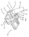
- Fig. 1 shows a perspective side view of a rail end piece 10 with a cord lock according to the invention 11.
- the rail end piece 11 has a head side 12 and a side surface 13 facing away from the side surface 13, a further side surface 14 is arranged.
- the side surface 14 is formed here as a front side.
- an opening 15 and in the side surface 14, an opening 16 is introduced.
- the openings 15 and 16 are formed in the embodiment shown here as bores 15, 16.
- the bore 16 is associated with the cord lock 11.
- the whisker 11 may be associated with the bore 15.
- the cord lock 11 has a bearing 17, which is designed here as a bearing ring 17.
- the bearing ring 17 is rotatable about 360 ° in the bore 16.
- the bearing ring 17 is locked by means of a locking connection, not shown here in the bore 16.
- the bearing ring 17 is connected at right angles to the side surface 14 fixed to the side surface 14, whereby falling out of the bearing ring 17 is prevented from the bore 16.
- the latching connection allows a pivoting or rotation of the bearing ring 17 about a bearing axis, which is aligned at right angles to the side surface 14.
- the cord lock 11 has a retaining element 18.
- the retaining element 18 is designed as a clamping lever 18 in the exemplary embodiment shown here.
- the clamping lever 18 is connected by means of a rotation axis 19 with the bearing ring 17.
- the rotation axis 19 is arranged in the bearing ring 17.
- the axis of rotation 19 is positioned centrally to the bearing ring 17 or in the region of an axis of symmetry of the bearing ring 17.
- bores are introduced into the bearing ring 17.
- the axis of rotation 19 is aligned parallel to the side surface 14 with respect to its longitudinal orientation.
- the clamping lever 18 is rotatable or pivotable about the axis of rotation 19.
- the bearing ring 17 is associated with a holding means 20, which is formed in the embodiment shown here as a pin 20.
- the pin 20 is aligned parallel to the axis of rotation 19.
- the clamping lever 18 and the pin 20 act to set or hold at least one cord not shown here in detail between the clamping lever 18 and the pin 20 together.
- the clamping lever 18 has a cord guide 21.
- the cord guide 21 has a channel for one or more cords, wherein the channel is inserted into the clamping lever 18.
- the line guide 21 has a guide pin 22 on an end of the clamping lever 18 facing away from the bearing ring 17. Due to the guide pin 22 can be ensured that one or more cords are reliably held within the channel of the clamping lever 18.
- the rail end 10 is inserted by means of a connecting piece 23 in one end of a guide rail not shown here.
- Fig. 2 shows a sectional side view of the rail end piece 10 with the cord lock 11 according to the invention Fig. 1 , Same features as before bear the same reference numbers. In that regard, reference is also made to the preceding description.
- a cord 24 is deflected within the rail end piece 10 by means of a deflection 25 in the direction of the cord lock 11.
- the cord 24 passes through an opening of the bearing ring 17 and between the clamping lever 18 and the pin 20 therethrough. Furthermore, the cord 24 is guided in a channel-like cord guide 21 of the clamping lever 18. An open side of the channel-like line guide faces the side surface 14, the bearing ring 17 and / or a shading plane.
- a plurality of cords 24 may also be provided.
- the guide pin 22 is spaced from a channel bottom of the channel-like line guide 21.
- the guide pin 22 is aligned parallel to the pin 20 with respect to its longitudinal orientation.
- the cord 24 extends through an opening 26, which is arranged in the region of the end facing away from the bearing ring 17 end of the clamping lever 18. The size of the opening 26 is determined by the position of the guide pin 22 and the distance between the channel bottom of the channel-like cord guide 21 and the guide pin 22.
- the clamping lever 18 is located in the representation shown here in an open position or an actuating position. In this position, the cord 24 is not clamped between the clamping lever 18 and the pin 20. Rather, the cord 24 in the longitudinal direction of the cord 24 can be actuated and can be used for adjusting a shading system.
- the pin 20 is positioned below the axis of rotation for the pivotability of the clamping lever 18.
- Above the axis of rotation of the clamping lever 18 has a stop 27.
- the stop 27 is formed in the embodiment shown here as a rounded stop surface. In the actuation position, the stop 27 abuts against the bearing ring 17.
- the maximum opening angle of the clamping lever 18 is limited. In the embodiment shown here, the maximum opening angle is 30 °.
- deviating opening angles are also conceivable, in particular in the range between 10 ° and 90 °.
- the opening angle refers to the angle between on the one hand the clamping lever 18 and / or the line guide 21 and on the other hand, the side surface 14 and / or a shading level. In a closed position, not shown here, or a holding position of the clamping lever 18, the opening angle is 0 °.
- the bearing ring 17 engages by means of an annular latching nose 28 behind an inner surface of the side surface 14. This is a secure hold of the bearing ring 17 in the bore 16 guaranteed.
- the bearing ring 17 may be formed in two parts, wherein for mounting in the bore 16, a first part of the bearing ring 17 is inserted from the outside into the bore 16 and a second part of the bearing ring 17 is inserted from the inside into the bore 16. The first part and the second part are firmly connected to each other by means of a screw and / or snap connection.
- cord lock 11 is based on the Fig. 1 and 2 explained in more detail:
- the clamping lever 18 In the holding position, the clamping lever 18 is aligned with an opening angle of 0 ° parallel to the side surface 14 and / or the shading plane. In this position, the cord 24 is clamped between the clamping lever 18 and the pin 20. If a shading system is now to be adjusted by actuating the cord 24, the cord 24 is grasped by a person and moved away from the shading system, the shading plane and / or the side surface 14. Here, the cord 24 takes the clamping lever 18 due to a contact between the cord 24 and the channel bottom of the channel-shaped cord guide 21, wherein the clamping lever 18 is pivoted about the axis of rotation 19. This pivotal movement about the axis of rotation 19 is limited by the stop 24, which abuts the bearing ring 17 at a predetermined opening angle.
- the cord 24 between the clamping lever 18 and the pin 20 is released.
- the cord 24 can be actuated to actuate the shading system in the longitudinal direction of the cord 24.
- the cord 24 is moved again in the direction of the shading system, the shading plane and / or the side surface 14.
- the clamping lever 18 is taken due to a contact between the cord 24 and the guide pin 22.
- the clamping lever 18 is pivoted about the axis of rotation 19 in the holding position, whereby the cord 24 is clamped between the clamping lever 18 and the pin 20.
- the clamping lever 18 and / or the pin 20 together with the bearing ring 17 at any time pivotable about the bearing axis For this purpose, a person grasps the cord 24 and pivots the cord together with the bearing ring 17 and / or the clamping lever 18 transversely to the longitudinal orientation of the cord 24 about the bearing axis. This ensures that the pin 20 is aligned with its clamping surface and / or clamping edge at any time at right angles to the cord 24. As a result, a durable and reliable operation of the cord lock 11 is considerably improved.
- the cord 24 due to the pivotability about the bearing axis, the cord 24 can be aligned vertically in a simple manner even at different installation angles.
Landscapes
- Engineering & Computer Science (AREA)
- Structural Engineering (AREA)
- Architecture (AREA)
- Civil Engineering (AREA)
- Blinds (AREA)
Description
- Die Erfindung betrifft ein Schnurschloss für eine Verschattungsanlage mit einem Lager, das um eine rechtwinklig zu einer Verschattungsebene ausgerichteten Lagerachse verschwenkbar ist, und mit einem Halteelement zum lösbaren Halten mindestens einer Schnur, wobei das Halteelement um eine parallel zur Verschattungsebene ausgerichteten Drehachse verschwenkbar ist.
- Ein derartiges Schnurschloss ist aus der
EP 0 693 613 A1 bekannt. Hierbei ist ein separates Gehäuse um eine rechtwinklig zu einer Seitenfläche eines Schienenendstückes bzw. zu einer Verschattungsebene, ausgerichteten Achse verschwenkbar gelagert. Für die Verschwenkbarkeit weist das separate Gehäuse einen Schwenkzapfen als das Lager auf, der in eine Öffnung des Schienenendstückes eingreift. Unterhalb des Schwenkzapfens bzw. Lagers und in dem separaten Gehäuse ist ein üblicher Schlossmechanismus vorgesehen, der eine Verschwenkbarkeit um eine parallel zur Seitenfläche bzw. zur Verschattungsebene ausgerichtete Achse vorsieht. - Nachteilig ist hierbei, dass aufgrund des separaten Gehäuses, in dem ein üblicher Schlossmechanismus angeordnet ist, viel Bauraum benötigt wird. Zudem kann das auf die Führungsschiene und/oder das Schienenendstück aufgesetzte separate Gehäuse klobig oder unästhetisch wirken.
- Ähnliche Schwenkschlösser zeigen auch die Druckschriften
DE 10 2006 001 604 A1 undDE 298 16 846 U1 - Es ist das der Erfindung zugrunde liegende Problem ein Schnurschloss der eingangs genannten Art derart weiterzuentwickeln, dass bei hoher Funktionalität und Zuverlässigkeit zugleich eine kompakte und ästhetisch ansprechende Bauweise ermöglicht ist.
- Zur Lösung des der Erfindung zugrunde liegenden Problems ist das Schnurschloss der eingangs genannten Art dadurch gekennzeichnet, dass die Drehachse des Halteelements innerhalb des Lagers angeordnet ist, wobei die Verschwenkbarkeit um die Drehachse mit der Verschwenkbarkeit um die Lagerachse baulich und/oder räumlich zusammengefasst ist.
- Hierbei ist von Vorteil, dass aufgrund der Anordnung der Drehachse des Haltelementes im Bereich des Lagers, insbesondere innerhalb des Lagers, deutlich kompaktere und zugleich im Betrieb zuverlässige Bauweisen ermöglicht sind. Insbesondere ist ein separates Gehäuse zum Aufnehmen eines Schlossmechanismus verzichtbar. Die Verschwenkbarkeit um die Drehachse ist mit der Verschwenkbarkeit um die Lagerachse baulich und/oder räumlich zusammengefasst.
- Vorzugsweise ist im Rahmen der vorliegenden Erfindung unter einer Achse, insbesondere einer Drehachse und/oder Lagerachse, eine materiell ausgebildete und/oder eine virtuelle Achse zu verstehen. Vorzugsweise ist unter einer Verschattungsebene die Ebene zu verstehen, die aufgrund eines der Verschattungsanlage zugeordneten Verschattungselementes, insbesondere einem Plisseestoff und/oder Jalousien, vorgegeben und/oder aufspannbar ist. Die Lagerachse kann zu einer Seitenfläche und/oder Frontseite einer Führungsschiene und/oder eines Schienenendstückes ausgerichtet sein. Vorzugweise ist die Führungsschiene zum Führen der mindestens einen Schnur ausgebildet. Es können eine oder mehrere Schnüre vorgesehen sein. Zudem kann die Führungsschiene zum Befestigen der Verschattungsanlage, insbesondere an einer Wand, einer Decke und/oder einem Sturz, vorgesehen sein. Insbesondere ist das Verschattungselement im montierten Zustand der Verschattungsanlage unterhalb der Führungsschiene angeordnet. Vorzugsweise ist die Drehachse parallel zur Seitenfläche der Führungsschiene und/oder des Schienenendstückes ausgerichtet. Das Schienenendstück kann als ein Abschlussstück für ein Ende der Führungsschiene ausgebildet sein. Des Weiteren kann das Schnurschloss, insbesondere in der Ausbildung eines Einsteckschlosses, in eine Öffnung der Führungsschiene und/oder des Schienenendstückes einbringbar sein. Insbesondere ist die Öffnung einer Seitenfläche und/oder einer Frontseite der Führungsschiene zugeordnet. Vorzugsweise ist die, insbesondere kreisförmige, Öffnung mittels einer Stanzvorrichtung herstellbar.
- Nach einer weiteren Ausführungsform sind die Drehachse und die Lagerachse in einer gemeinsamen, insbesondere rechtwinklig zur Verschattungsebene und/oder Seitenfläche ausgerichteten, Ebene angeordnet. Hierdurch ist eine besonders kompakte und zugleich funktionale Bauweise realisierbar.
- Das Halteelement kann mit einem Haltemittel zum lösbaren Halten der Schnur zwischen dem Halteelement und dem Haltemittel zusammenwirken. Insbesondere ist die mindestens eine Schnur zwischen dem Haltemittel und dem Halteelement klemmbar. Das Halteelement ist in einer geschlossenen Position oder einer Halteposition, wenn die Schnur zwischen dem Halteelement und dem Haltemittel fest gehalten ist. Ist die Schnur zwischen dem Halteelement und dem Haltemittel nicht fest gehalten, ist das Halteelement in einer geöffneten Position oder Betätigungsposition. Insbesondere ist in der Betätigungsposition des Haltelementes die Verschattungsanlage, vorzugsweise das Verschattungselement in der Verschattungsebene, mittels der Schnur verstellbar.
- Vorzugsweise ist das Haltemittel dem Lager zugeordnet. Hierdurch wird das Haltemittel bei einer Verdrehung und/oder Verschwenkung des Lagers um die Lagerachse ebenfall verdreht und/oder verschwenkt. Insbesondere ist das Haltemittel bezüglich seiner Längsausrichtung parallel zur Drehachse ausgerichtet. Das Lager ist somit zusammen mit der Drehachse und dem Haltemittel verdrehbar und/oder verschwenkbar. Unabhängig von einer Verdrehung und/oder Verschwenkung des Lagers verbleibt die räumliche Ausrichtung des Haltemittels in Bezug zur Drehachse des Halteelementes, und insbesondere zum Halteelement, gleich. Vorzugsweise erfolgt eine Verdrehung und/oder Verschwenkung des Lagers aufgrund einer Betätigung der Schnur. Hierbei bleibt insbesondere die Ausrichtung der Drehachse und/oder des Haltemittels zur Zugrichtung der Schnur gleich. Hierdurch ist eine dauerhaft zuverlässige Funktionalität des Schnurschlosses verbessert.
- Gemäß einer Weiterbildung ist das Haltemittel innerhalb des Lagers angeordnet. Hierdurch wird die Ausbildung einer kompakten Bauweise weiter begünstigt. Das Haltemittel kann als ein mit dem Lager fest verbundener Stift ausgebildet sein. Ein solcher Stift lässt sich besonders einfach mittels Bohrungen in dem Lager befestigen. Vorzugsweise hat der Stift eine Klemmkante und/oder Klemmfläche. Der Stift, die Klemmkante und/oder die Klemmfläche können aus Metall, Nichteisenmetall oder Kunststoff ausgebildet sein.
- Nach einer weiteren Ausführungsform weist das Halteelement eine Schnurführung auf. Insbesondere ist die Schnur aufgrund der Schnurführung dem Halteelement zugeordnet. Vorzugsweise ist aufgrund der Schnurführung eine Betätigung des Halteelementes mittels der Schnur auf zuverlässige Weise realisierbar. Das Halteelement kann als ein Klemmhebel ausgebildet sein. Aufgrund der Hebelwirkung ist hierdurch bei geringen Betätigungskräften eine hinreichende Klemmkraft zum Festklemmen der Schnur zwischen dem Klemmhebel und dem Haltemittel realisierbar.
- Das Lager kann mittels einer Rastverbindung und/oder Steckverbindung in einer Öffnung in einer Seitenfläche einer Führungsschiene und/oder eines Schienenendstückes befestigbar sein. Hierdurch ist das Lager und/oder das Schnurschloss besonders einfach und schnell an einer Führungsschiene und/oder einem Schienenendstück montierbar. Vorzugsweise ist die Öffnung als eine Bohrung ausgebildet.
- Des Weiteren kann das Lager einteilig oder zweiteilig ausgebildet sein. Bei einer einstückigen bzw. einteiligen Ausbildung des Lagers ist das Lager vorzugsweise von Außen in die Öffnung einbringbar. Bei einer zweistückigen bzw. zweiteiligen Ausbildung des Lagers werden zur Montage des Lagers in der Öffnung vorzugsweise ein erster Teil des Lagers von Außen und ein zweiter Teil des Lagers von Innen in die Öffnung eingebracht. Insbesondere sind das erste Teil und das zweite Teil mittels einer Steckverbindung und/oder einer Schraubverbindung miteinander verbindbar.
- Gemäß einer Weiterbildung weist das Lager einen Durchbruch zum Durchführen der Schnur auf. Hierdurch ist die mindestens eine Schnur aus der Führungsschiene und/oder dem Schienenendstück nach Außen führbar. Weiter kann das Lager als ein um die Lagerachse drehbarer Lagerring ausgebildet sein. Vorzugsweise ist die Drehachse des Halteelementes in dem Lagerring angeordnet. Hierdurch ist eine besonders kompakte und funktionale Bauweise realiserbar.
- Nach einer weiteren Ausführungsform ist das Halteelement und/oder das Lager um 360°, insbesondere um 180°, um die Lagerachse verschwenkbar. Hierdurch ist das Schnurschloss mittels der Schnur unter verschiedenen Winkeln bequem bedienbar. Zudem ist die Schnur und/oder das Schnurschloss bei einer Montage der Verschattungsanlage unter einem beliebigen Anlagenwinkel lotrecht ausrichtbar. Hierdurch ergibt ist ein ästhetisch ansprechender Anblick realisierbar. Vorzugsweise ist unter einem Anlagenwinkel der Winkel zu verstehen, der sich im montierten Zustand der Verschattungsanlage zwischen der Führungsschiene und der Horizontalen ergibt. Insbesondere ist das Schnurschloss für Verschattungsanlagen zum Verschatten einer Dreiecksöffnung und/oder einer Kreisausschnittsöffnung, insbesondere einer Viertelkreisöffnung, vorgesehen. Bei einer Kreisausschnittsöffnung und/oder Viertelkreisöffnung, insbesondere mit einer lotrechten Leibung, kann die Führungsschiene lotrecht, vorzugsweise an der lotrechten Leibung, befestigt sein. Vorzugsweise ist ein bewegbares, insbesondere veschwenkbares, Verschattungsprofil vorgesehen. Das Verschattungsprofil kann zum Verschatten einer beispielsweise Viertelkreisöffnung um 90° schwenkbar gelagert sein, insbesondere um ein Verschattungselement mit dem Verschattungsprofil aus einer lotrechten Stellung des Verschattungsprofils in eine horizontale Stellung des Verschattungsprofils und/oder umgekehrt zu führen. In der lotrechten Stellung des Verschattungsprofils ist das Verschattungsprofil vorzugsweise parallel zur Führungsschiene angeordnet.
- Vorzugsweise ist ausgehend von der lotrechten Ausrichtung der Schnur, insbesondere bei einem Anlagenwinkel von 0°, eine Verschwenkbarkeit von 90° nach links und 90° nach rechts gegeben ist. Eine derartige Verschwenkbarkeit reicht für eine bequeme Bedienbarkeit für Verschattungsanlagen, die mit einem üblichen Anlagenwinkel montiert sind, aus.
- Von besonderem Vorteil ist die Verwendung eines erfindungsgemäßen Schnurschlosses mit einer Verschattungsanlage, insbesondere einem Plissee und/oder einer Jalousie. Die Ausrichtung des Haltemittels in Bezug auf die Drehachse des Halteelementes verbleibt bei einer Verschwenkung des Lagers und/oder Halteelementes gleich. Die mindestens eine Schnur ist immer optimal zwischen dem Halteelement und dem Haltemittel ausgerichtet. Hierdurch ist eine hohe Funktionalität und Zuverlässigkeit realisiert. Zudem ist eine Raum sparende und/oder ästhetische Bauweise realisierbar.
- Nachfolgend wird die Erfindung anhand der Figuren näher erläutert. Es zeigen:
- Fig. 1
- eine perspektivische Seitenansicht eines Schieneendstückes mit einem erfindungsgemäßen Schnurschloss, und
- Fig. 2
- eine geschnittene Seitenansicht des Schienenendstückes mit dem erfindungsgemäßen Schnurschloss gemäß
Fig. 1 . -
Fig. 1 zeigt eine perspektivische Seitenansicht eines Schieneendstückes 10 mit einem erfindungsgemäßen Schnurschloss 11. Das Schienenendstück 11 hat eine Kopfseite 12 und eine Seitenfläche 13. Von der Seitenfläche 13 abgewandt ist eine weitere Seitenfläche 14 angeordnet. Die Seitenfläche 14 ist hier als eine Frontseite ausgebildet. In der Seitenfläche 13 ist eine Öffnung 15 und in der Seitenfläche 14 eine Öffnung 16 eingebracht. Die Öffnungen 15 und 16 sind in dem hier gezeigten Ausführungsbeispiel als Bohrungen 15, 16 ausgebildet. - Der Bohrung 16 ist das Schnurschloss 11 zugeordnet. In einer alternativen Ausführungsform kann das Schnurrschloss 11 der Bohrung 15 zugeordnet sein. Das Schnurschloss 11 hat ein Lager 17, das hier als ein Lagerring 17 ausgebildet ist. Der Lagerring 17 ist um 360° drehbar in der Bohrung 16 angeordnet. Durch den Lagerring 17 kann mindestens eine hier nicht näher dargestellte Schnur durchgeführt werden. In dem hier gezeigten Ausführungsbeispiel ist der Lagerring 17 mittels einer hier nicht näher dargestellten Rastverbindung in die Bohrung 16 eingerastet. Hierdurch ist der Lagerring 17 rechtwinklig zur Seitenfläche 14 fest mit der Seitenfläche 14 verbunden, wodurch ein Herausfallen des Lagerringes 17 aus der Bohrung 16 vermieden ist. Zugleich erlaubt die Rastverbindung eine Verschwenkung bzw. Verdrehung des Lagerringes 17 um eine Lagerachse, die rechtwinklig zur Seitenfläche 14 ausgerichtet ist.
- Des Weiteren hat das Schnurschloss 11 ein Halteelement 18. Das Halteelement 18 ist in dem hier gezeigten Ausführungsbeispiel als ein Klemmhebel 18 ausgebildet. Der Klemmhebel 18 ist mittels einer Drehachse 19 mit dem Lagerring 17 verbunden. Hierbei ist die Drehachse 19 in dem Lagerring 17 angeordnet. Die Drehachse 19 ist mittig zum Lagerring 17 bzw. im Bereich einer Symmetrieachse des Lagerringes 17 positioniert. Zum Aufnehmen der Drehachse 19 sind Bohrungen in den Lagerring 17 eingebracht. Weiter ist die Drehachse 19 bezüglich ihrer Längsausrichtung parallel zur Seitenfläche 14 ausgerichtet. Der Klemmhebel 18 ist um die Drehachse 19 drehbar bzw. verschwenkbar.
- Dem Lagerring 17 ist ein Haltemittel 20 zugeordnet, das in dem hier gezeigten Ausführungsbeispiel als ein Stift 20 ausgebildet ist. Der Stift 20 ist parallel zur Drehachse 19 ausgerichtet. Zur Befestigung des Stiftes 20 mit dem Lagerring 17 sind Bohrungen in den Lagerring 17 eingebracht. Der Klemmhebel 18 und der Stift 20 wirken zum Festsetzen bzw. Festhalten mindestens einer hier nicht näher gezeigten Schnur zwischen dem Klemmhebel 18 und dem Stift 20 zusammen.
- Der Klemmhebel 18 weist eine Schnurführung 21 auf. Die Schnurführung 21 hat einen Kanal für eine oder mehrere Schnüre, wobei der Kanal in den Klemmhebel 18 eingebracht ist. Weiter weist die Schnurführung 21 einen Führungsstift 22 an einem von dem Lagerring 17 abgewandten Ende des Klemmhebels 18 auf. Aufgrund des Führungsstiftes 22 ist gewährleistbar, dass eine oder mehrere Schnüre zuverlässig innerhalb des Kanals des Klemmhebels 18 gehalten sind.
- Das Schienenendstück 10 ist mittels eines Verbindungsstückes 23 in ein Ende einer hier nicht näher dargestellten Führungsschiene einsteckbar.
-
Fig. 2 zeigt eine geschnittene Seitenansicht des Schienenendstückes 10 mit dem erfindungsgemäßen Schnurschloss 11 gemäßFig. 1 . Gleiche Merkmale wie zuvor tragen die gleichen Bezugszeichen. Insoweit wird auch auf die vorangegangene Beschreibung verwiesen. - Eine Schnur 24 wird innerhalb des Schienendstückes 10 mittels einer Umlenkung 25 in Richtung des Schnurschlosses 11 umgelenkt. Die Schnur 24 verläuft durch einen Durchbruch des Lagerringes 17 und zwischen dem Klemmhebel 18 und dem Stift 20 hindurch. Des Weiteren ist die Schnur 24 in einer kanalartig ausgebildeten Schnurführung 21 des Klemmhebels 18 geführt. Eine offene Seite der kanalartigen Schnurführung ist der Seitenfläche 14, dem Lagerring 17 und/oder einer Verschattungsebene zugewandt. Alternativ zu der hier dargestellten einen Schnur 24 können auch mehrere Schnüre 24 vorgesehen sein.
- An einem von dem Lagerring 17 abgewandt liegenden Ende des Klemmhebels 18 ist der Führungsstift 22 angeordnet. Hierbei ist der Führungsstift 22 von einem Kanalgrund der kanalartigen Schnurführung 21 beabstandet. Der Führungsstift 22 ist hinsichtlich seiner Längsausrichtung parallel zum Stift 20 ausgerichtet. Die Schnur 24 verläuft durch eine Öffnung 26, die im Bereich des von dem Lagerring 17 abgewandten Endes des Klemmhebels 18 angeordnet ist. Die Größe der Öffnung 26 wird durch die Lage des Führungsstiftes 22 bzw. dem Abstand zwischen dem Kanalgrund der kanalartigen Schnurführung 21 und dem Führungsstift 22 bestimmt.
- Der Klemmhebel 18 befindet sich in der hier gezeigten Darstellung in einer geöffneten Position oder einer Betätigungsposition. In dieser Position ist die Schnur 24 nicht zwischen dem Klemmhebel 18 und dem Stift 20 fest geklemmt. Vielmehr ist die Schnur 24 in Längsrichtung der Schnur 24 betätigbar und kann zum Verstellen einer Verschattungsanlage genutzt werden.
- Der Stift 20 ist unterhalb der Drehachse für die Verschwenkbarkeit des Klemmhebels 18 positioniert. Oberhalb der Drehachse weist der Klemmhebel 18 einen Anschlag 27 auf. Der Anschlag 27 ist in der hier gezeigten Ausführungsform als eine abgerundete Anschlagsfläche ausgebildet. In der Betätigungsposition schlägt der Anschlag 27 an den Lagerring 17 an. Hierdurch ist der maximale Öffnungswinkel des Klemmhebels 18 begrenzt. Bei dem hier gezeigten Ausführungsbeispiel beträgt der maximale Öffnungswinkel 30°. Alternativ sind auch hiervon abweichende Öffnungswinkel denkbar, insbesondere im Bereich zwischen 10° und 90°. Der Öffnungswinkel bezieht sich auf den Winkel zwischen einerseits dem Klemmhebel 18 und/oder der Schnurführung 21 und andererseits der Seitenfläche 14 und/oder einer Verschattungsebene. In einer hier nicht näher dargestellten geschlossenen Position oder einer Halteposition des Klemmhebels 18 beträgt der Öffnungswinkel 0°.
- Der Lagerring 17 greift mittels einer ringförmigen Rastnase 28 hinter eine Innenfläche der Seitenfläche 14. Hierdurch ist ein sicherer Halt des Lagerringes 17 in der Bohrung 16 gewährleistet. In einer alternativen Ausführungsform kann der Lagerring 17 zweiteilig ausgebildet sein, wobei zur Montage in der Bohrung 16 ein erstes Teil des Lagerringes 17 von Außen in die Bohrung 16 eingeführt wird und ein zweites Teil des Lagerringes 17 von Innen in die Bohrung 16 eingeführt wird. Das erste Teil und das zweite Teil sind mittels einer Schraub- und/oder Schnappverbindung fest miteinander verbindbar.
- Nachfolgend wird das erfindungsgemäße Schnurschloss 11 anhand der
Fig. 1 und2 näher erläutert: - In der Halteposition ist der Klemmhebel 18 mit einem Öffnungswinkel von 0° parallel zur Seitenfläche 14 und/oder der Verschattungsebene ausgerichtet. In dieser Position wird die Schnur 24 zwischen dem Klemmhebel 18 und dem Stift 20 festgeklemmt. Soll nun eine Verschattungsanlage über eine Betätigung der Schnur 24 verstellt werden, wird die Schnur 24 von einer Person ergriffen und von der Verschattungsanlage, der Verschattungsebene und/oder der Seitenfläche 14 weg bewegt. Hierbei nimmt die Schnur 24 den Klemmhebel 18 aufgrund eines Kontakts zwischen der Schnur 24 und dem Kanalgrund der kanalförmigen Schnurführung 21 mit, wobei der Klemmhebel 18 um die Drehachse 19 verschwenkt wird. Diese Verschwenkbewegung um die Drehachse 19 wird durch den Anschlag 24 begrenzt, der bei einem vorgegebenen Öffnungswinkel an den Lagerring 17 anstößt.
- In dieser Betätigungsposition ist die Schnur 24 zwischen dem Klemmhebel 18 und dem Stift 20 frei gegeben. Somit kann die Schnur 24 zum Betätigen der Verschattungsanlage in Längsrichtung der Schnur 24 betätigt werden. Ist die Verschattungsanlage in der gewünschten Stellung, wird die Schnur 24 wieder in Richtung der Verschattungsanlage, der Verschattungsebene und/oder der Seitenfläche 14 bewegt. Hierbei wird der Klemmhebel 18 aufgrund eines Kontakts zwischen der Schnur 24 und dem Führungsstift 22 mitgenommen. Der Klemmhebel 18 wird um die Drehachse 19 in die Halteposition verschwenkt, wodurch die Schnur 24 zwischen dem Klemmhebel 18 und dem Stift 20 eingeklemmt ist.
- Zudem ist der Klemmhebel 18 und/oder der Stift 20 zusammen mit dem Lagerring 17 jederzeit um die Lagerachse verschwenkbar. Hierzu ergreift eine Person die Schnur 24 und verschwenkt die Schnur zusammen mit dem Lagerring 17 und/oder dem Klemmhebel 18 quer zur Längsausrichtung der Schnur 24 um die Lagerachse. Hierbei ist gewährleistet, dass der Stift 20 mit seiner Klemmfläche und/oder Klemmkante jederzeit rechtwinklig zur Schnur 24 ausgerichtet ist. Hierdurch wird eine dauerhafte und zuverlässige Funktionsfähigkeit des Schnurschlosses 11 erheblich verbessert. Zudem lässt sich aufgrund der Verschwenkbarkeit um die Lagerachse die Schnur 24 auch bei verschiedenen Anlagenwinkeln auf einfache Weise lotrecht ausrichten.
- Hierdurch ist eine einfache und zugleich zuverlässige Bedienung des Schnurschlosses 11 und/oder der Verschattungsanlage gegeben.
-
- 10
- Schienenendstück
- 11
- Schnurschloss
- 12
- Kopfseite
- 13
- Seitenfläche
- 14
- Seitenfläche
- 15
- Öffnung
- 16
- Öffnung
- 17
- Lager
- 18
- Halteelement
- 19
- Drehachse
- 20
- Haltemittel
- 21
- Schnurführung
- 22
- Führungsstift
- 23
- Verbindungsstück
- 24
- Schnur
- 25
- Umlenkung
- 26
- Öffnung
- 27
- Anschlag
- 28
- Rastnase
Claims (9)
- Schnurschloss für eine Verschattungsanlage mit einem Lager (17), das um eine rechtwinklig zu einer Verschattungsebene ausgerichteten Lagerachse verschwenkbar ist, und mit einem Halteelement (18) zum lösbaren Halten mindestens einer Schnur (24), wobei das Halteelement (18) um eine parallel zur Verschattungsebene ausgerichteten Drehachse (19) verschwenkbar ist, dadurch gekennzeichnet, dass die Drehachse (19) des Halteelements (18) innerhalb des Lagers (17) angeordnet ist, wobei die Verschwenkbarkeit um die Drehachse (19) mit der Verschwenkbarkeit um die Lagerachse baulich und/oder räumlich zusammengefasst ist.
- Schnurschloss nach Anspruch 1, dadurch gekennzeichnet, dass die Drehachse (19) und die Lagerachse in einer gemeinsamen, insbesondere rechtwinklig zur Verschattungsebene ausgerichteten, Ebene angeordnet sind.
- Schnurschloss nach Anspruch 1 oder 2, dadurch gekennzeichnet, dass das Halteelement (18) mit einem Haltemittel (20) zum lösbaren Halten der Schnur (24) zwischen dem Halteelement (18) und dem Haltemittel (20) zusammenwirkt, wobei vorzugsweise das Haltemittel (20) dem Lager (17) zugeordnet ist und/oder das Haltemittel (20) bezüglich seiner Längsausrichtung parallel zur Drehachse (19) ausgerichtet ist.
- Schnurschloss nach Anspruch 3, dadurch gekennzeichnet, dass das Haltemittel (20) innerhalb des Lagers (17) angeordnet ist und/oder dass das Haltemittel (20) als ein mit dem Lager (17) fest verbundener Stift ausgebildet ist, wobei vorzugsweise der Stift eine Klemmkante und/oder Klemmfläche hat.
- Schnurschloss nach einem der vorhergehenden Ansprüche, dadurch gekennzeichnet, dass das Halteelement (18) eine Schnurführung (21) aufweist und/oder dass das Halteelement (18) als ein Klemmhebel ausgebildet ist.
- Schnurschloss nach einem der vorhergehenden Ansprüche, dadurch gekennzeichnet, dass das Lager (17) mittels einer Rastverbindung und/oder Steckverbindung in einer Öffnung (15, 16) in einer Seitenfläche (13, 14) einer Führungsschiene und/oder eines Schienenendstückes befestigbar ist, wobei vorzugsweise das Lager (17) einteilig oder zweiteilig ausgebildet ist.
- Schnurschloss nach einem der vorhergehenden Ansprüche, dadurch gekennzeichnet, dass das Lager (17) einen Durchbruch zum Durchführen der Schnur (24) aufweist und/oder dass das Lager (17) als ein um die Lagerachse drehbarer Lagerring ausgebildet ist.
- Schnurschloss nach einem der vorhergehenden Ansprüche, dadurch gekennzeichnet, dass das Halteelement (18) und/oder das Lager (17) um 360°, insbesondere um 180°, um die Lagerachse verschwenkbar ist, wobei vorzugsweise ausgehend von einer lotrechten Ausrichtung der Schnur (24) und/oder des Halteelementes (18), insbesondere bei einem Anlagenwinkel von 0°, eine Verschwenkbarkeit von 90° nach links und 90° nach rechts gegeben ist.
- Verwendung eines Schnurschlosses (11) nach einem der vorhergehenden Ansprüche mit einer Verschattungsanlage, insbesondere einem Plissee und/oder einer Jalousie.
Applications Claiming Priority (1)
| Application Number | Priority Date | Filing Date | Title |
|---|---|---|---|
| DE102011110833A DE102011110833A1 (de) | 2011-08-23 | 2011-08-23 | Schnurschloss |
Publications (2)
| Publication Number | Publication Date |
|---|---|
| EP2573312A1 EP2573312A1 (de) | 2013-03-27 |
| EP2573312B1 true EP2573312B1 (de) | 2014-05-14 |
Family
ID=46750227
Family Applications (1)
| Application Number | Title | Priority Date | Filing Date |
|---|---|---|---|
| EP20120181501 Active EP2573312B1 (de) | 2011-08-23 | 2012-08-23 | Schnurschloss |
Country Status (3)
| Country | Link |
|---|---|
| EP (1) | EP2573312B1 (de) |
| DE (1) | DE102011110833A1 (de) |
| DK (1) | DK2573312T3 (de) |
Cited By (1)
| Publication number | Priority date | Publication date | Assignee | Title |
|---|---|---|---|---|
| DE102019127636B3 (de) * | 2019-10-14 | 2021-01-21 | Warema Kunststofftechnik Und Maschinenbau Gmbh | Schnurschloss für Sonnenschutzanlagen |
Family Cites Families (4)
| Publication number | Priority date | Publication date | Assignee | Title |
|---|---|---|---|---|
| DE9411621U1 (de) | 1994-07-18 | 1995-11-16 | HANSA Sicht- und Sonnenschutz GmbH, 22523 Hamburg | Faltenstore mit Schnurschloß |
| DE29816846U1 (de) * | 1998-09-19 | 1999-01-28 | Reko Kunststofftechnik und Maschinenbau GmbH, 97828 Marktheidenfeld | Positionierbare Schnurbremse |
| DE102006001604B4 (de) * | 2006-01-11 | 2013-09-12 | Warema Kunststofftechnik Und Maschinenbau Gmbh | Schnurbremse |
| NL1034063C2 (nl) * | 2007-06-29 | 2008-12-30 | Textiles B V Ag | Koordslot voor gebruik in een raambedekking. |
-
2011
- 2011-08-23 DE DE102011110833A patent/DE102011110833A1/de not_active Withdrawn
-
2012
- 2012-08-23 EP EP20120181501 patent/EP2573312B1/de active Active
- 2012-08-23 DK DK12181501T patent/DK2573312T3/da active
Cited By (2)
| Publication number | Priority date | Publication date | Assignee | Title |
|---|---|---|---|---|
| DE102019127636B3 (de) * | 2019-10-14 | 2021-01-21 | Warema Kunststofftechnik Und Maschinenbau Gmbh | Schnurschloss für Sonnenschutzanlagen |
| EP3808229A1 (de) | 2019-10-14 | 2021-04-21 | WAREMA Kunststofftechnik und Maschinenbau GmbH | Schnurrschloss für sonnenschutzanlagen |
Also Published As
| Publication number | Publication date |
|---|---|
| EP2573312A1 (de) | 2013-03-27 |
| DE102011110833A1 (de) | 2013-02-28 |
| DK2573312T3 (da) | 2014-08-18 |
Similar Documents
| Publication | Publication Date | Title |
|---|---|---|
| EP2216485A2 (de) | Schnurspannvorrichtung und damit ausgerüstete Vorhanganlage | |
| DE102012023261A1 (de) | Kraftfahrzeugschloss | |
| DE602006000733T2 (de) | Schloss für eine Eingangstür in einem Sektionaltor, insbesondere für Garagen | |
| DE202013101591U1 (de) | Halterung zur Montage von gespannten Sonnen- oder Blickschutzvorrichtungen | |
| EP2801685B1 (de) | Laufrollenträger für einen Schiebetürbeschlag | |
| EP3631120B1 (de) | Seilhalterung und laufelement | |
| DE102013100922B4 (de) | Laufteil zum Führen eines Möbelteils in einer Führungsrichtung über eine Führungsschiene und Möbelbeschlag | |
| EP2573312A1 (de) | Schnurschloss | |
| DE202009015473U1 (de) | Lamellenjalousie | |
| DE102008039442B4 (de) | Kfz-Fronthaubenschloss | |
| EP3183408A1 (de) | Steuerelement für eine beschlaganordnung | |
| EP3168394B1 (de) | Sperrkloben für einen türöffner oder ein schliessblech | |
| DE202010008353U1 (de) | Markise | |
| DE102011011201B4 (de) | Insektenschutzvorrichtung, insbesondere Türvorrichtung, vorzugsweise für die Türöffnung eines Wohnwagens und/oder eines Wohnmobils und/oder für eine Türöffnung, eine Fensteröffnung oder eine Dachhaubenöffnung | |
| EP3553260B1 (de) | Falleneinsatz mit tagstellung zur bedingten freigabe einer schlossfalle eines türschlossmechanismus | |
| DE202010008567U1 (de) | Montagevorrichtung für einen Strahler | |
| DE202006000857U1 (de) | Fensterrolloanordnung | |
| DE102015111300B4 (de) | Fahrzeugschiebedach | |
| DE102018206224B4 (de) | Fensterheberbaugruppe mit einem gegen ein missbräuchliches Lösen gesicherten Mittnehmer | |
| EP3527740B1 (de) | Dachfenster | |
| EP2578786A2 (de) | Halteeinrichtung für Tür- oder Fensterflügel | |
| EP2770154B1 (de) | Bündelungselement zum Bündeln von mindestens zwei Betätigungsschnüren für eine Verschattungsanlage | |
| EP3808229B1 (de) | Schnurschloss für sonnenschutzanlagen | |
| DE102005002312B4 (de) | Mitnehmer für Seilzug-Fensterheber | |
| EP4283089A1 (de) | Vorrichtung zur sicherung von rollläden und rolltoren |
Legal Events
| Date | Code | Title | Description |
|---|---|---|---|
| PUAI | Public reference made under article 153(3) epc to a published international application that has entered the european phase |
Free format text: ORIGINAL CODE: 0009012 |
|
| AK | Designated contracting states |
Kind code of ref document: A1 Designated state(s): AL AT BE BG CH CY CZ DE DK EE ES FI FR GB GR HR HU IE IS IT LI LT LU LV MC MK MT NL NO PL PT RO RS SE SI SK SM TR |
|
| AX | Request for extension of the european patent |
Extension state: BA ME |
|
| 17P | Request for examination filed |
Effective date: 20130927 |
|
| RBV | Designated contracting states (corrected) |
Designated state(s): AL AT BE BG CH CY CZ DE DK EE ES FI FR GB GR HR HU IE IS IT LI LT LU LV MC MK MT NL NO PL PT RO RS SE SI SK SM TR |
|
| GRAP | Despatch of communication of intention to grant a patent |
Free format text: ORIGINAL CODE: EPIDOSNIGR1 |
|
| RIC1 | Information provided on ipc code assigned before grant |
Ipc: E06B 9/324 20060101AFI20131018BHEP |
|
| INTG | Intention to grant announced |
Effective date: 20131115 |
|
| GRAS | Grant fee paid |
Free format text: ORIGINAL CODE: EPIDOSNIGR3 |
|
| GRAA | (expected) grant |
Free format text: ORIGINAL CODE: 0009210 |
|
| AK | Designated contracting states |
Kind code of ref document: B1 Designated state(s): AL AT BE BG CH CY CZ DE DK EE ES FI FR GB GR HR HU IE IS IT LI LT LU LV MC MK MT NL NO PL PT RO RS SE SI SK SM TR |
|
| REG | Reference to a national code |
Ref country code: GB Ref legal event code: FG4D Free format text: NOT ENGLISH |
|
| REG | Reference to a national code |
Ref country code: AT Ref legal event code: REF Ref document number: 668450 Country of ref document: AT Kind code of ref document: T Effective date: 20140615 |
|
| REG | Reference to a national code |
Ref country code: IE Ref legal event code: FG4D Free format text: LANGUAGE OF EP DOCUMENT: GERMAN |
|
| REG | Reference to a national code |
Ref country code: DE Ref legal event code: R096 Ref document number: 502012000735 Country of ref document: DE Effective date: 20140626 |
|
| REG | Reference to a national code |
Ref country code: DK Ref legal event code: T3 Effective date: 20140814 |
|
| REG | Reference to a national code |
Ref country code: NL Ref legal event code: T3 |
|
| REG | Reference to a national code |
Ref country code: LT Ref legal event code: MG4D |
|
| PG25 | Lapsed in a contracting state [announced via postgrant information from national office to epo] |
Ref country code: FI Free format text: LAPSE BECAUSE OF FAILURE TO SUBMIT A TRANSLATION OF THE DESCRIPTION OR TO PAY THE FEE WITHIN THE PRESCRIBED TIME-LIMIT Effective date: 20140514 Ref country code: GR Free format text: LAPSE BECAUSE OF FAILURE TO SUBMIT A TRANSLATION OF THE DESCRIPTION OR TO PAY THE FEE WITHIN THE PRESCRIBED TIME-LIMIT Effective date: 20140815 Ref country code: LT Free format text: LAPSE BECAUSE OF FAILURE TO SUBMIT A TRANSLATION OF THE DESCRIPTION OR TO PAY THE FEE WITHIN THE PRESCRIBED TIME-LIMIT Effective date: 20140514 Ref country code: NO Free format text: LAPSE BECAUSE OF FAILURE TO SUBMIT A TRANSLATION OF THE DESCRIPTION OR TO PAY THE FEE WITHIN THE PRESCRIBED TIME-LIMIT Effective date: 20140814 Ref country code: CY Free format text: LAPSE BECAUSE OF FAILURE TO SUBMIT A TRANSLATION OF THE DESCRIPTION OR TO PAY THE FEE WITHIN THE PRESCRIBED TIME-LIMIT Effective date: 20140514 Ref country code: IS Free format text: LAPSE BECAUSE OF FAILURE TO SUBMIT A TRANSLATION OF THE DESCRIPTION OR TO PAY THE FEE WITHIN THE PRESCRIBED TIME-LIMIT Effective date: 20140914 |
|
| PG25 | Lapsed in a contracting state [announced via postgrant information from national office to epo] |
Ref country code: RS Free format text: LAPSE BECAUSE OF FAILURE TO SUBMIT A TRANSLATION OF THE DESCRIPTION OR TO PAY THE FEE WITHIN THE PRESCRIBED TIME-LIMIT Effective date: 20140514 Ref country code: LV Free format text: LAPSE BECAUSE OF FAILURE TO SUBMIT A TRANSLATION OF THE DESCRIPTION OR TO PAY THE FEE WITHIN THE PRESCRIBED TIME-LIMIT Effective date: 20140514 Ref country code: ES Free format text: LAPSE BECAUSE OF FAILURE TO SUBMIT A TRANSLATION OF THE DESCRIPTION OR TO PAY THE FEE WITHIN THE PRESCRIBED TIME-LIMIT Effective date: 20140514 Ref country code: SE Free format text: LAPSE BECAUSE OF FAILURE TO SUBMIT A TRANSLATION OF THE DESCRIPTION OR TO PAY THE FEE WITHIN THE PRESCRIBED TIME-LIMIT Effective date: 20140514 Ref country code: HR Free format text: LAPSE BECAUSE OF FAILURE TO SUBMIT A TRANSLATION OF THE DESCRIPTION OR TO PAY THE FEE WITHIN THE PRESCRIBED TIME-LIMIT Effective date: 20140514 Ref country code: PL Free format text: LAPSE BECAUSE OF FAILURE TO SUBMIT A TRANSLATION OF THE DESCRIPTION OR TO PAY THE FEE WITHIN THE PRESCRIBED TIME-LIMIT Effective date: 20140514 |
|
| PG25 | Lapsed in a contracting state [announced via postgrant information from national office to epo] |
Ref country code: PT Free format text: LAPSE BECAUSE OF FAILURE TO SUBMIT A TRANSLATION OF THE DESCRIPTION OR TO PAY THE FEE WITHIN THE PRESCRIBED TIME-LIMIT Effective date: 20140915 |
|
| PG25 | Lapsed in a contracting state [announced via postgrant information from national office to epo] |
Ref country code: EE Free format text: LAPSE BECAUSE OF FAILURE TO SUBMIT A TRANSLATION OF THE DESCRIPTION OR TO PAY THE FEE WITHIN THE PRESCRIBED TIME-LIMIT Effective date: 20140514 Ref country code: CZ Free format text: LAPSE BECAUSE OF FAILURE TO SUBMIT A TRANSLATION OF THE DESCRIPTION OR TO PAY THE FEE WITHIN THE PRESCRIBED TIME-LIMIT Effective date: 20140514 Ref country code: SK Free format text: LAPSE BECAUSE OF FAILURE TO SUBMIT A TRANSLATION OF THE DESCRIPTION OR TO PAY THE FEE WITHIN THE PRESCRIBED TIME-LIMIT Effective date: 20140514 Ref country code: RO Free format text: LAPSE BECAUSE OF FAILURE TO SUBMIT A TRANSLATION OF THE DESCRIPTION OR TO PAY THE FEE WITHIN THE PRESCRIBED TIME-LIMIT Effective date: 20140514 |
|
| REG | Reference to a national code |
Ref country code: DE Ref legal event code: R097 Ref document number: 502012000735 Country of ref document: DE |
|
| PLBE | No opposition filed within time limit |
Free format text: ORIGINAL CODE: 0009261 |
|
| STAA | Information on the status of an ep patent application or granted ep patent |
Free format text: STATUS: NO OPPOSITION FILED WITHIN TIME LIMIT |
|
| PG25 | Lapsed in a contracting state [announced via postgrant information from national office to epo] |
Ref country code: MC Free format text: LAPSE BECAUSE OF FAILURE TO SUBMIT A TRANSLATION OF THE DESCRIPTION OR TO PAY THE FEE WITHIN THE PRESCRIBED TIME-LIMIT Effective date: 20140514 Ref country code: LU Free format text: LAPSE BECAUSE OF FAILURE TO SUBMIT A TRANSLATION OF THE DESCRIPTION OR TO PAY THE FEE WITHIN THE PRESCRIBED TIME-LIMIT Effective date: 20140823 |
|
| 26N | No opposition filed |
Effective date: 20150217 |
|
| PG25 | Lapsed in a contracting state [announced via postgrant information from national office to epo] |
Ref country code: BE Free format text: LAPSE BECAUSE OF NON-PAYMENT OF DUE FEES Effective date: 20140831 Ref country code: IT Free format text: LAPSE BECAUSE OF FAILURE TO SUBMIT A TRANSLATION OF THE DESCRIPTION OR TO PAY THE FEE WITHIN THE PRESCRIBED TIME-LIMIT Effective date: 20140514 |
|
| REG | Reference to a national code |
Ref country code: IE Ref legal event code: MM4A |
|
| REG | Reference to a national code |
Ref country code: DE Ref legal event code: R097 Ref document number: 502012000735 Country of ref document: DE Effective date: 20150217 |
|
| REG | Reference to a national code |
Ref country code: FR Ref legal event code: ST Effective date: 20150430 |
|
| PG25 | Lapsed in a contracting state [announced via postgrant information from national office to epo] |
Ref country code: SI Free format text: LAPSE BECAUSE OF FAILURE TO SUBMIT A TRANSLATION OF THE DESCRIPTION OR TO PAY THE FEE WITHIN THE PRESCRIBED TIME-LIMIT Effective date: 20140514 |
|
| PG25 | Lapsed in a contracting state [announced via postgrant information from national office to epo] |
Ref country code: FR Free format text: LAPSE BECAUSE OF NON-PAYMENT OF DUE FEES Effective date: 20140901 Ref country code: IE Free format text: LAPSE BECAUSE OF NON-PAYMENT OF DUE FEES Effective date: 20140823 |
|
| REG | Reference to a national code |
Ref country code: CH Ref legal event code: PL |
|
| PG25 | Lapsed in a contracting state [announced via postgrant information from national office to epo] |
Ref country code: LI Free format text: LAPSE BECAUSE OF NON-PAYMENT OF DUE FEES Effective date: 20150831 Ref country code: CH Free format text: LAPSE BECAUSE OF NON-PAYMENT OF DUE FEES Effective date: 20150831 |
|
| PG25 | Lapsed in a contracting state [announced via postgrant information from national office to epo] |
Ref country code: SM Free format text: LAPSE BECAUSE OF FAILURE TO SUBMIT A TRANSLATION OF THE DESCRIPTION OR TO PAY THE FEE WITHIN THE PRESCRIBED TIME-LIMIT Effective date: 20140514 |
|
| PG25 | Lapsed in a contracting state [announced via postgrant information from national office to epo] |
Ref country code: BG Free format text: LAPSE BECAUSE OF FAILURE TO SUBMIT A TRANSLATION OF THE DESCRIPTION OR TO PAY THE FEE WITHIN THE PRESCRIBED TIME-LIMIT Effective date: 20140514 Ref country code: MT Free format text: LAPSE BECAUSE OF FAILURE TO SUBMIT A TRANSLATION OF THE DESCRIPTION OR TO PAY THE FEE WITHIN THE PRESCRIBED TIME-LIMIT Effective date: 20140514 |
|
| PG25 | Lapsed in a contracting state [announced via postgrant information from national office to epo] |
Ref country code: TR Free format text: LAPSE BECAUSE OF FAILURE TO SUBMIT A TRANSLATION OF THE DESCRIPTION OR TO PAY THE FEE WITHIN THE PRESCRIBED TIME-LIMIT Effective date: 20140514 Ref country code: HU Free format text: LAPSE BECAUSE OF FAILURE TO SUBMIT A TRANSLATION OF THE DESCRIPTION OR TO PAY THE FEE WITHIN THE PRESCRIBED TIME-LIMIT; INVALID AB INITIO Effective date: 20120823 |
|
| PG25 | Lapsed in a contracting state [announced via postgrant information from national office to epo] |
Ref country code: MK Free format text: LAPSE BECAUSE OF FAILURE TO SUBMIT A TRANSLATION OF THE DESCRIPTION OR TO PAY THE FEE WITHIN THE PRESCRIBED TIME-LIMIT Effective date: 20140514 |
|
| PG25 | Lapsed in a contracting state [announced via postgrant information from national office to epo] |
Ref country code: AL Free format text: LAPSE BECAUSE OF FAILURE TO SUBMIT A TRANSLATION OF THE DESCRIPTION OR TO PAY THE FEE WITHIN THE PRESCRIBED TIME-LIMIT Effective date: 20140514 |
|
| REG | Reference to a national code |
Ref country code: DE Ref legal event code: R082 Ref document number: 502012000735 Country of ref document: DE Representative=s name: TAPPE, UDO, DIPL.-PHYS. DR.RER.NAT., DE |
|
| P01 | Opt-out of the competence of the unified patent court (upc) registered |
Effective date: 20230515 |
|
| PGFP | Annual fee paid to national office [announced via postgrant information from national office to epo] |
Ref country code: NL Payment date: 20250825 Year of fee payment: 14 |
|
| PGFP | Annual fee paid to national office [announced via postgrant information from national office to epo] |
Ref country code: DK Payment date: 20250825 Year of fee payment: 14 Ref country code: DE Payment date: 20250827 Year of fee payment: 14 |
|
| PGFP | Annual fee paid to national office [announced via postgrant information from national office to epo] |
Ref country code: GB Payment date: 20250826 Year of fee payment: 14 |
|
| PGFP | Annual fee paid to national office [announced via postgrant information from national office to epo] |
Ref country code: AT Payment date: 20250819 Year of fee payment: 14 |