EP3806178A1 - Module de batterie - Google Patents
Module de batterie Download PDFInfo
- Publication number
- EP3806178A1 EP3806178A1 EP20827983.6A EP20827983A EP3806178A1 EP 3806178 A1 EP3806178 A1 EP 3806178A1 EP 20827983 A EP20827983 A EP 20827983A EP 3806178 A1 EP3806178 A1 EP 3806178A1
- Authority
- EP
- European Patent Office
- Prior art keywords
- output electrode
- electrode base
- battery module
- limiting element
- end plate
- Prior art date
- Legal status (The legal status is an assumption and is not a legal conclusion. Google has not performed a legal analysis and makes no representation as to the accuracy of the status listed.)
- Granted
Links
- 238000004146 energy storage Methods 0.000 abstract description 2
- 238000003780 insertion Methods 0.000 description 16
- 230000037431 insertion Effects 0.000 description 16
- 238000010586 diagram Methods 0.000 description 12
- 238000013461 design Methods 0.000 description 10
- 239000000470 constituent Substances 0.000 description 6
- 238000009434 installation Methods 0.000 description 4
- 241000397426 Centroberyx lineatus Species 0.000 description 2
- 238000005520 cutting process Methods 0.000 description 2
- 230000002452 interceptive effect Effects 0.000 description 2
- 238000000034 method Methods 0.000 description 2
- 238000012986 modification Methods 0.000 description 2
- 230000004048 modification Effects 0.000 description 2
- 230000004888 barrier function Effects 0.000 description 1
- 229920001971 elastomer Polymers 0.000 description 1
- 239000000806 elastomer Substances 0.000 description 1
- 238000009413 insulation Methods 0.000 description 1
- 239000000463 material Substances 0.000 description 1
- 239000007769 metal material Substances 0.000 description 1
- 238000012545 processing Methods 0.000 description 1
Images


Classifications
-
- H—ELECTRICITY
- H01—ELECTRIC ELEMENTS
- H01M—PROCESSES OR MEANS, e.g. BATTERIES, FOR THE DIRECT CONVERSION OF CHEMICAL ENERGY INTO ELECTRICAL ENERGY
- H01M50/00—Constructional details or processes of manufacture of the non-active parts of electrochemical cells other than fuel cells, e.g. hybrid cells
- H01M50/20—Mountings; Secondary casings or frames; Racks, modules or packs; Suspension devices; Shock absorbers; Transport or carrying devices; Holders
- H01M50/204—Racks, modules or packs for multiple batteries or multiple cells
- H01M50/207—Racks, modules or packs for multiple batteries or multiple cells characterised by their shape
- H01M50/209—Racks, modules or packs for multiple batteries or multiple cells characterised by their shape adapted for prismatic or rectangular cells
-
- H—ELECTRICITY
- H01—ELECTRIC ELEMENTS
- H01M—PROCESSES OR MEANS, e.g. BATTERIES, FOR THE DIRECT CONVERSION OF CHEMICAL ENERGY INTO ELECTRICAL ENERGY
- H01M10/00—Secondary cells; Manufacture thereof
- H01M10/04—Construction or manufacture in general
- H01M10/0481—Compression means other than compression means for stacks of electrodes and separators
-
- H—ELECTRICITY
- H01—ELECTRIC ELEMENTS
- H01M—PROCESSES OR MEANS, e.g. BATTERIES, FOR THE DIRECT CONVERSION OF CHEMICAL ENERGY INTO ELECTRICAL ENERGY
- H01M10/00—Secondary cells; Manufacture thereof
- H01M10/04—Construction or manufacture in general
- H01M10/0468—Compression means for stacks of electrodes and separators
-
- H—ELECTRICITY
- H01—ELECTRIC ELEMENTS
- H01M—PROCESSES OR MEANS, e.g. BATTERIES, FOR THE DIRECT CONVERSION OF CHEMICAL ENERGY INTO ELECTRICAL ENERGY
- H01M50/00—Constructional details or processes of manufacture of the non-active parts of electrochemical cells other than fuel cells, e.g. hybrid cells
- H01M50/20—Mountings; Secondary casings or frames; Racks, modules or packs; Suspension devices; Shock absorbers; Transport or carrying devices; Holders
- H01M50/204—Racks, modules or packs for multiple batteries or multiple cells
-
- H—ELECTRICITY
- H01—ELECTRIC ELEMENTS
- H01M—PROCESSES OR MEANS, e.g. BATTERIES, FOR THE DIRECT CONVERSION OF CHEMICAL ENERGY INTO ELECTRICAL ENERGY
- H01M50/00—Constructional details or processes of manufacture of the non-active parts of electrochemical cells other than fuel cells, e.g. hybrid cells
- H01M50/20—Mountings; Secondary casings or frames; Racks, modules or packs; Suspension devices; Shock absorbers; Transport or carrying devices; Holders
- H01M50/262—Mountings; Secondary casings or frames; Racks, modules or packs; Suspension devices; Shock absorbers; Transport or carrying devices; Holders with fastening means, e.g. locks
- H01M50/264—Mountings; Secondary casings or frames; Racks, modules or packs; Suspension devices; Shock absorbers; Transport or carrying devices; Holders with fastening means, e.g. locks for cells or batteries, e.g. straps, tie rods or peripheral frames
-
- H—ELECTRICITY
- H01—ELECTRIC ELEMENTS
- H01M—PROCESSES OR MEANS, e.g. BATTERIES, FOR THE DIRECT CONVERSION OF CHEMICAL ENERGY INTO ELECTRICAL ENERGY
- H01M50/00—Constructional details or processes of manufacture of the non-active parts of electrochemical cells other than fuel cells, e.g. hybrid cells
- H01M50/20—Mountings; Secondary casings or frames; Racks, modules or packs; Suspension devices; Shock absorbers; Transport or carrying devices; Holders
- H01M50/296—Mountings; Secondary casings or frames; Racks, modules or packs; Suspension devices; Shock absorbers; Transport or carrying devices; Holders characterised by terminals of battery packs
-
- H—ELECTRICITY
- H01—ELECTRIC ELEMENTS
- H01M—PROCESSES OR MEANS, e.g. BATTERIES, FOR THE DIRECT CONVERSION OF CHEMICAL ENERGY INTO ELECTRICAL ENERGY
- H01M50/00—Constructional details or processes of manufacture of the non-active parts of electrochemical cells other than fuel cells, e.g. hybrid cells
- H01M50/50—Current conducting connections for cells or batteries
- H01M50/543—Terminals
-
- Y—GENERAL TAGGING OF NEW TECHNOLOGICAL DEVELOPMENTS; GENERAL TAGGING OF CROSS-SECTIONAL TECHNOLOGIES SPANNING OVER SEVERAL SECTIONS OF THE IPC; TECHNICAL SUBJECTS COVERED BY FORMER USPC CROSS-REFERENCE ART COLLECTIONS [XRACs] AND DIGESTS
- Y02—TECHNOLOGIES OR APPLICATIONS FOR MITIGATION OR ADAPTATION AGAINST CLIMATE CHANGE
- Y02E—REDUCTION OF GREENHOUSE GAS [GHG] EMISSIONS, RELATED TO ENERGY GENERATION, TRANSMISSION OR DISTRIBUTION
- Y02E60/00—Enabling technologies; Technologies with a potential or indirect contribution to GHG emissions mitigation
- Y02E60/10—Energy storage using batteries
-
- Y—GENERAL TAGGING OF NEW TECHNOLOGICAL DEVELOPMENTS; GENERAL TAGGING OF CROSS-SECTIONAL TECHNOLOGIES SPANNING OVER SEVERAL SECTIONS OF THE IPC; TECHNICAL SUBJECTS COVERED BY FORMER USPC CROSS-REFERENCE ART COLLECTIONS [XRACs] AND DIGESTS
- Y02—TECHNOLOGIES OR APPLICATIONS FOR MITIGATION OR ADAPTATION AGAINST CLIMATE CHANGE
- Y02P—CLIMATE CHANGE MITIGATION TECHNOLOGIES IN THE PRODUCTION OR PROCESSING OF GOODS
- Y02P70/00—Climate change mitigation technologies in the production process for final industrial or consumer products
- Y02P70/50—Manufacturing or production processes characterised by the final manufactured product
Definitions
- Embodiments of this application relate to the field of energy storage devices, and in particular, to a battery module.
- a battery module usually includes an end plate and an output electrode base.
- the end plate is configured to compress a plurality of battery cells.
- the output electrode base is mounted on the end plate and is configured to secure an output electrode of the battery module.
- the output electrode base is mounted to the end plate, the output electrode base is prone to falling off during transport. Therefore, it is necessary to design a new battery module to prevent the output electrode base from falling off the end plate during transport.
- Embodiments of this application provide a battery module to solve a prior-art problem and prevent an output electrode base from falling off during transport.
- An embodiment of this application provides a battery module, including an output electrode base and an end plate, where the output electrode base is inserted into and fitted to the end plate; a first limiting element is disposed on the output electrode base, a limiting plate is disposed on the end plate, and the first limiting element is fitted to the limiting plate to limit relative movement of the output electrode base and the end plate along a first direction (XI); a stop hole is provided in one of the output electrode base and the end plate, and a second limiting element is disposed on the other; the second limiting element is accommodated in the stop hole; and the second limiting element is fitted to the stop hole to limit relative movement of the output electrode base and the end plate along a second direction (X2); and an extension direction of the first direction (XI) is opposite to an extension direction of the second direction (X2).
- the end plate includes a body; the stop hole is provided in the body along a height direction (Z) of the battery module; and the output electrode base includes a base plate, and the second limiting element protrudes from the base plate along the height direction (Z) of the battery module.
- a through groove is provided in the base plate; a first end of the second limiting element is connected to an inner wall of the through groove; and there is a gap between parts, other than the first end, of the second limiting element and the inner wall of the through groove.
- the through groove includes an opening, and the opening is disposed away from the first end of the second limiting element.
- the second limiting element includes an elastic section; the through groove is provided in the base plate; a first end of the elastic section is connected to the inner wall of the through groove; and a second end of the elastic section protrudes from the base plate.
- the second limiting element includes a fixed section and the elastic section; a first end of the fixed section is connected to the inner wall of the through groove; the first end of the elastic section is connected to a second end of the fixed section; and the second end of the elastic section protrudes from the base plate.
- a thickness (W1) of the elastic section is less than a thickness (W2) of the fixed section.
- an angle ⁇ between the elastic section and the fixed section meets: 90° ⁇ 180°.
- the angle ⁇ between the elastic section and the fixed section meets: 135° ⁇ 170°.
- the first limiting element and the second limiting element are disposed on the output electrode base, and the limiting plate and the stop hole are disposed on the end plate.
- the first limiting element is fitted to the limiting plate to limit the relative movement of the output electrode base and the end plate along the first direction
- the second limiting element is fitted to the stop hole to limit the relative movement of the output electrode base and the end plate along the second direction, thereby improving connection reliability of the output electrode base during transport.
- the second limiting element is accommodated in the stop hole.
- the output electrode base is inserted into a slot without interference and further inserted until the first limiting element is fitted to the limiting plate, thereby facilitating an assembly process of the output electrode base.
- no interfering object is disposed on a side of the end plate facing away from the limiting plate, and installation space of a battery cell near the end plate is neither occupied, thereby improving energy density of the battery module.
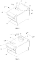
- FIG. 1 is a schematic structural diagram of a battery module according to an embodiment of this application.
- FIG. 2 is a schematic exploded view of fitting of an output electrode base to an end plate in a battery module according to an embodiment of this application.
- FIG. 3 is a schematic structural diagram of an angle of an output electrode base in a battery module according to an embodiment of this application.
- FIG. 4 is a schematic structural diagram of another angle of an output electrode base in a battery module according to an embodiment of this application.
- an embodiment of this application provides a battery module 100, including an output electrode base 1 and an end plate 2.
- the end plate 2 may be made of a metal material.
- the output electrode base 1 is configured to provide insulation protection for an output electrode of the battery module 100, and may be made of a plastic material.
- the output electrode base 1 is inserted into and fitted to the end plate 2.
- the output electrode base 1 may be inserted into the end plate 2 in a length direction (X) of the battery module 100.
- the output electrode base 1 may alternatively be inserted into and fitted to the end plate 2 in another direction of the battery module 100.
- an insertion element 13 is disposed on the output electrode base 1 and a slot 23 is provided in the end plate 2.
- the slot 23 extends along the length direction (X) of the battery module 100
- the insertion element 13 also extends along the length direction (X) of the battery module 100
- the insertion element 13 is inserted into the slot 23.
- the slot 23 may be in an approximate swallow-tail shape
- the insertion element 13 may also have an outline of an approximate swallow-tail shape, so as to limit relative movement of the output electrode base 1 on the end plate 2 along a height direction (Z) and a width direction (Y) of the battery module 100.
- a first limiting element 14 is disposed on the output electrode base 1.
- the first limiting element 14 may be an end surface formed at one end of the insertion element 13, or may be a projection or another structure fixed on the insertion element 13 or fixed on another position of the output electrode base 1.
- the first limiting element 14 is an end surface formed at one end of the insertion element 13.
- a limiting plate 24 is disposed on the end plate 2, and the limiting plate 24 may extend upward along the height direction (Z) of the battery module to form a barrier to the first limiting element 14.
- the first limiting element 14 is fitted to the limiting plate 24 to limit relative movement of the output electrode base 1 and the end plate 2 along a first direction (XI). In this way, after the output electrode base 1 is mounted to the end plate 2, the output electrode base 1 does not fall off along the first direction (XI) when the end plate 2 and the output electrode base 1 are tilted or overturned during transport of the output electrode base 1 and the end plate 2.
- a stop hole 22 is provided in one of the output electrode base 1 and the end plate 2, and a second limiting element 12 is disposed on the other.
- the second limiting element 12 is accommodated in the stop hole 22.
- the second limiting element 12 is disposed on the output electrode base 1, and the stop hole 22 is provided in the end plate 2.
- the second limiting element 12 is fitted to the stop hole 22 to limit the relative movement of the output electrode base 1 and the end plate 2 along a second direction (X2).
- An extension direction of the first direction (XI) is opposite to an extension direction of the second direction (X2).
- the first direction (XI) and the second direction (X2) are two opposite directions in the length direction (X) of the battery module 100.
- the second limiting element 12 is disposed on the output electrode base 1, the stop hole 22 is provided in the end plate 2, and the second limiting element 12 is accommodated in the stop hole 22.
- the output electrode base is inserted into a slot 23 without interference and further inserted until the first limiting element 14 is fitted to the limiting plate 24, thereby facilitating an assembly process of the output electrode base.
- no interfering object is disposed on a side of the end plate 2 facing away from the limiting plate 24, and installation space of a battery cell near the end plate 2 is neither occupied, thereby improving energy density of the battery module 100.
- the output electrode base 1 During transport of the output electrode base 1 and the end plate 2, if the output electrode base 1 and the end plate 2 are tilted or overturned along the first direction (X1), the output electrode base 1 does not fall off because the first limiting element 14 is fitted to the limiting plate 24. If the output electrode base 1 and the end plate 2 are tilted or overturned along the second direction (X2), the output electrode base 1 neither falls off because the second limiting element 12 is fitted to the stop hole 22, thereby improving connection reliability between the output electrode base 1 and the end plate 2 during transport.
- the end plate 2 includes a body 21, and the stop hole 22 is provided in the body 21 along the height direction (Z) of the battery module 100.
- the output electrode base 1 includes a base plate 11, and the second limiting element 12 protrudes from the base plate 11 along the height direction (Z) of the battery module 100.
- the insertion element 13 of the output electrode base 1 is inserted into the slot 23 of the end plate 2.
- the second limiting element 12 is accommodated in the stop hole 22.
- the second limiting element 12 may not be in contact with a hole wall 221 of the stop hole 22, or the second limiting element 12 comes in contact with the hole wall 221, but the two do not press against and interfere with each other.
- the second limiting element 12 may press against and interfere with the hole wall 221 of the stop hole 22 to prevent the output electrode base 1 from falling off.
- the second limiting element 12 is disposed on the base plate 11 of the output electrode base 1, and an existing hole in the body 21 of the end plate 2 is used as the stop hole 22. Therefore, occupied space can be reduced, and the energy density of the battery module 100 can be improved.
- a through groove 111 is provided in the base plate 11. As shown in FIG. 4 , a first end 12a of the second limiting element 12 is connected to an inner wall of the through groove 111, and there is a gap between parts, other than the first end 12a, of the second limiting element 12 and the inner wall of the through groove 111.
- the through groove 111 is formed during processing of the second limiting element 12.
- the gap provided in the through groove 111 also makes the second limiting element 12 elastic to some extent.
- the second limiting element 12 is elastically deformed to enter the stop hole 22.
- the through groove 111 includes an opening 111a, and the opening 111a is disposed away from the first end 12a of the second limiting element 12.
- the through groove 111 with the opening 111a can be obtained by means of a simple cutting process, and therefore the second limiting element 12 can be obtained by means of a relatively simple cutting process.
- disposition of the opening 111a also makes the output electrode base 1 lighter and further improves the energy density of the battery module 100.
- FIG. 5 is a schematic structural diagram of another output electrode base in a battery module according to an embodiment of this application, and FIG. 6 is an enlarged view of position A in FIG. 5 .
- a second limiting element 12 includes an elastic section 121.
- a through groove 111 is provided in a base plate 11, a first end 121a of the elastic section 121 is connected to an inner wall of the through groove 111, and a second end 121b of the elastic section 121 protrudes from the base plate 11.
- the elastic section 121 may be an elastomer directly formed on the base plate 11, or the elastic section 121 may be a block-like structure and a corresponding notch is provided in the elastic section 121 to make the elastic section 121 elastic to some extent.
- a raised tilt section is formed by the elastic section 121.
- a bevel structure of the raised tilt section can play a guiding role, so that the second limiting element 12 enters a stop hole 22 of the end plate 2.
- FIG. 7 is a schematic structural diagram of still another output electrode base in a battery module according to an embodiment of this application, and FIG. 8 is an enlarged view of position B in FIG. 7 .
- a second limiting element 12 includes a fixed section 122 and an elastic section 121, a first end 122a of the fixed section 122 is connected to an inner wall of a through groove 111, a first end 121a of the elastic section 121 is connected to a second end 122b of the fixed section 122, and a second end 121b of the elastic section 121 protrudes from the base plate 11.
- a flat and straight section is formed by the fixed section 122, and a raised tilt section is formed by the elastic section 121.
- a bevel of the raised tilt section can play a guiding role, so that the second limiting element 12 enters a stop hole 22.
- Disposition of the fixed section 122 can increase a length size of the entire second limiting element 12, thereby improving elastic performance of the second limiting element 12.
- the fixed section 122 may be a sheet-like structure directly formed on the base plate 11, or the fixed section 122 may be a block-like structure.
- a notch may alternatively be provided in the block-like fixed section 122 to make the fixed section elastic to some extent.
- no notch may be provided in the block-like fixed section 122, and the second limiting element 12 enters the stop hole 22 with the help of elastic performance of the elastic section 121.
- FIG. 9 is a main view of an output electrode base fitted to an end plate in a battery module according to an embodiment of this application, and FIG. 10 is a cross-sectional view of FIG. 9 in a C-C direction.
- a thickness (W1) of an elastic section 121 is less than a thickness (W2) of a fixed section 122.
- the relatively thick fixed section 122a guarantees a connection strength of a second limiting element 12, and the relatively thin elastic section 121 improves elastic performance of the second limiting element 12.
- both the thickness (W1) of the elastic section 121 and the thickness (W2) of the fixed section 122 are average thickness.
- the second limiting element 12 may have a curve structure or a bevel structure.
- the elastic section 121 can form a bevel structure.
- an angle ⁇ between the elastic section 121 and the fixed section 122 meets: 90° ⁇ 180°, to form the bevel structure of the elastic section 121. This can facilitate insertion and assembly of the output electrode base 1.
- the angle ⁇ between the elastic section 121 and the fixed section 122 is an angle between a side, protruding from the base plate 11, of the elastic section 121 (refer to FIG. 8 ) and a side, protruding from the base plate 11, of the fixed section 122.
- the angle ⁇ between the elastic section 121 and the fixed section 122 meets: 135° ⁇ 170°. Such angle facilitates a guiding role of the bevel structure and does not damage the second limiting element 12.
- FIG. 11 is a schematic structural diagram of yet another output electrode base in an battery module according to an embodiment of this application. As shown in FIG. 11 , there are three second limiting elements 12.
- One, two, or three stop holes 22 may be provided, depending on a quantity of second limiting elements 12. Certainly, there may be more second limiting elements 12 and stop holes 22, which is not further limited herein.
- two stop holes 22 there are two stop holes 22.
- Two hole walls 221 are both planar, and are coplanar in a width direction (Y) of the battery module 100.
- second ends 121b of the elastic sections 121 of the second limiting elements 12 that are fitted to the stop holes 22 may be in an aligned state, as shown in FIG. 7 .
- the hole walls 221 may alternatively be nonplanar.
- the second limiting element 12 is implemented in a plurality of manners, so as to adapt to different forms of end plates 2.
Landscapes
- Chemical & Material Sciences (AREA)
- Chemical Kinetics & Catalysis (AREA)
- Electrochemistry (AREA)
- General Chemical & Material Sciences (AREA)
- Engineering & Computer Science (AREA)
- Manufacturing & Machinery (AREA)
- Battery Mounting, Suspending (AREA)
Applications Claiming Priority (2)
| Application Number | Priority Date | Filing Date | Title |
|---|---|---|---|
| CN201921323599.7U CN210403878U (zh) | 2019-08-15 | 2019-08-15 | 电池模组 |
| PCT/CN2020/106465 WO2021027601A1 (fr) | 2019-08-15 | 2020-07-31 | Module de batterie |
Publications (3)
| Publication Number | Publication Date |
|---|---|
| EP3806178A1 true EP3806178A1 (fr) | 2021-04-14 |
| EP3806178A4 EP3806178A4 (fr) | 2021-11-03 |
| EP3806178B1 EP3806178B1 (fr) | 2022-12-28 |
Family
ID=70338662
Family Applications (1)
| Application Number | Title | Priority Date | Filing Date |
|---|---|---|---|
| EP20827983.6A Active EP3806178B1 (fr) | 2019-08-15 | 2020-07-31 | Module de batterie |
Country Status (5)
| Country | Link |
|---|---|
| US (1) | US11588200B2 (fr) |
| EP (1) | EP3806178B1 (fr) |
| CN (1) | CN210403878U (fr) |
| HU (1) | HUE061033T2 (fr) |
| WO (1) | WO2021027601A1 (fr) |
Families Citing this family (3)
| Publication number | Priority date | Publication date | Assignee | Title |
|---|---|---|---|---|
| CN210403878U (zh) | 2019-08-15 | 2020-04-24 | 宁德时代新能源科技股份有限公司 | 电池模组 |
| CN112531299B (zh) | 2020-11-27 | 2023-02-24 | 宁德时代新能源科技股份有限公司 | 一种安装座、电池及用电设备 |
| CN112928374B (zh) * | 2021-02-23 | 2022-09-30 | 远景动力技术(江苏)有限公司 | 用于电池模组的端板和电池模组 |
Family Cites Families (12)
| Publication number | Priority date | Publication date | Assignee | Title |
|---|---|---|---|---|
| WO2015064097A1 (fr) * | 2013-10-31 | 2015-05-07 | パナソニックIpマネジメント株式会社 | Module de batterie |
| CN106450078B (zh) * | 2016-08-31 | 2022-12-23 | 艾森(宁波)智能科技有限公司 | 一种多功能电池盒 |
| JP6752674B2 (ja) * | 2016-09-30 | 2020-09-09 | ビークルエナジージャパン株式会社 | 組電池 |
| WO2018155093A1 (fr) * | 2017-02-27 | 2018-08-30 | 日立オートモティブシステムズ株式会社 | Module de batterie secondaire |
| CN206547229U (zh) * | 2017-02-28 | 2017-10-10 | 上海海拉电子有限公司 | 一种卡合结构 |
| CN206727133U (zh) * | 2017-05-15 | 2017-12-08 | 宁德时代新能源科技股份有限公司 | 电池模组 |
| CN109994663B (zh) | 2017-12-29 | 2021-09-14 | 宁德时代新能源科技股份有限公司 | 复合端板以及电池模组 |
| CN207896173U (zh) * | 2018-03-23 | 2018-09-21 | 宁德时代新能源科技股份有限公司 | 电池模组 |
| CN208819951U (zh) * | 2018-10-17 | 2019-05-03 | 宁德时代新能源科技股份有限公司 | 电池模组及其保护组件 |
| CN209571451U (zh) * | 2019-02-12 | 2019-11-01 | 欣旺达电动汽车电池有限公司 | 电池模组 |
| CN209822775U (zh) * | 2019-06-03 | 2019-12-20 | 宁德时代新能源科技股份有限公司 | 端子保护装置及电池模组 |
| CN210403878U (zh) * | 2019-08-15 | 2020-04-24 | 宁德时代新能源科技股份有限公司 | 电池模组 |
-
2019
- 2019-08-15 CN CN201921323599.7U patent/CN210403878U/zh active Active
-
2020
- 2020-07-31 HU HUE20827983A patent/HUE061033T2/hu unknown
- 2020-07-31 WO PCT/CN2020/106465 patent/WO2021027601A1/fr unknown
- 2020-07-31 EP EP20827983.6A patent/EP3806178B1/fr active Active
- 2020-12-17 US US17/125,858 patent/US11588200B2/en active Active
Also Published As
| Publication number | Publication date |
|---|---|
| US20210126315A1 (en) | 2021-04-29 |
| HUE061033T2 (hu) | 2023-05-28 |
| EP3806178B1 (fr) | 2022-12-28 |
| US11588200B2 (en) | 2023-02-21 |
| EP3806178A4 (fr) | 2021-11-03 |
| CN210403878U (zh) | 2020-04-24 |
| WO2021027601A1 (fr) | 2021-02-18 |
Similar Documents
| Publication | Publication Date | Title |
|---|---|---|
| EP3806178A1 (fr) | Module de batterie | |
| US9054456B2 (en) | Power connector assembly having an alignment body | |
| EP3799182A1 (fr) | Batterie secondaire, bloc-batterie et dispositif électrique | |
| EP3703154A1 (fr) | Module de batterie | |
| EP3955331A1 (fr) | Module de batterie et partie d'isolation | |
| US11217981B2 (en) | Busway and corresponding electrical component | |
| JP2016031897A (ja) | 蓄電装置 | |
| US20210159568A1 (en) | Hook coupling structure and battery pack case using same | |
| US9306242B2 (en) | Lead-acid battery moss guard | |
| CN218975681U (zh) | 一种输出极底座与端板的安装结构及电池模组 | |
| KR20210103930A (ko) | 배터리 모듈 | |
| US11784372B2 (en) | End plate for battery module, and battery module | |
| US20130295791A1 (en) | Connector | |
| KR100850832B1 (ko) | 건전지 수납용 케이스 및 이를 구비한 전자 장치 | |
| JP3749011B2 (ja) | 携帯電気機器の電池ケース | |
| CN215697358U (zh) | 外定位组件及翻边模具 | |
| CN108717556A (zh) | 一种暂存仓及卡片暂存器 | |
| CN207935066U (zh) | 一种泵固定结构 | |
| CN220474742U (zh) | 方形电池壳体及电池 | |
| CN219801076U (zh) | 电池及电池装置 | |
| US20220394867A1 (en) | Device having fool-proofing structure and cabinet type device assembly | |
| CN220107912U (zh) | 一种角码及边框组件 | |
| CN219371263U (zh) | 单体电池 | |
| US11394189B1 (en) | Cable fixing device and antenna | |
| CN220553567U (zh) | 电池、电池装置 |
Legal Events
| Date | Code | Title | Description |
|---|---|---|---|
| STAA | Information on the status of an ep patent application or granted ep patent |
Free format text: STATUS: UNKNOWN |
|
| STAA | Information on the status of an ep patent application or granted ep patent |
Free format text: STATUS: THE INTERNATIONAL PUBLICATION HAS BEEN MADE |
|
| PUAI | Public reference made under article 153(3) epc to a published international application that has entered the european phase |
Free format text: ORIGINAL CODE: 0009012 |
|
| STAA | Information on the status of an ep patent application or granted ep patent |
Free format text: STATUS: REQUEST FOR EXAMINATION WAS MADE |
|
| 17P | Request for examination filed |
Effective date: 20201229 |
|
| AK | Designated contracting states |
Kind code of ref document: A1 Designated state(s): AL AT BE BG CH CY CZ DE DK EE ES FI FR GB GR HR HU IE IS IT LI LT LU LV MC MK MT NL NO PL PT RO RS SE SI SK SM TR |
|
| AX | Request for extension of the european patent |
Extension state: BA ME |
|
| REG | Reference to a national code |
Ref country code: DE Ref legal event code: R079 Ref document number: 602020007257 Country of ref document: DE Free format text: PREVIOUS MAIN CLASS: H99Z9999999999 Ipc: H01M0050543000 |
|
| A4 | Supplementary search report drawn up and despatched |
Effective date: 20211001 |
|
| RIC1 | Information provided on ipc code assigned before grant |
Ipc: H01M 50/543 20210101AFI20210927BHEP |
|
| GRAP | Despatch of communication of intention to grant a patent |
Free format text: ORIGINAL CODE: EPIDOSNIGR1 |
|
| STAA | Information on the status of an ep patent application or granted ep patent |
Free format text: STATUS: GRANT OF PATENT IS INTENDED |
|
| DAV | Request for validation of the european patent (deleted) | ||
| DAX | Request for extension of the european patent (deleted) | ||
| GRAS | Grant fee paid |
Free format text: ORIGINAL CODE: EPIDOSNIGR3 |
|
| INTG | Intention to grant announced |
Effective date: 20221019 |
|
| GRAA | (expected) grant |
Free format text: ORIGINAL CODE: 0009210 |
|
| STAA | Information on the status of an ep patent application or granted ep patent |
Free format text: STATUS: THE PATENT HAS BEEN GRANTED |
|
| AK | Designated contracting states |
Kind code of ref document: B1 Designated state(s): AL AT BE BG CH CY CZ DE DK EE ES FI FR GB GR HR HU IE IS IT LI LT LU LV MC MK MT NL NO PL PT RO RS SE SI SK SM TR |
|
| REG | Reference to a national code |
Ref country code: GB Ref legal event code: FG4D |
|
| REG | Reference to a national code |
Ref country code: CH Ref legal event code: EP |
|
| REG | Reference to a national code |
Ref country code: DE Ref legal event code: R096 Ref document number: 602020007257 Country of ref document: DE |
|
| REG | Reference to a national code |
Ref country code: AT Ref legal event code: REF Ref document number: 1541048 Country of ref document: AT Kind code of ref document: T Effective date: 20230115 |
|
| REG | Reference to a national code |
Ref country code: IE Ref legal event code: FG4D |
|
| REG | Reference to a national code |
Ref country code: LT Ref legal event code: MG9D |
|
| PG25 | Lapsed in a contracting state [announced via postgrant information from national office to epo] |
Ref country code: SE Free format text: LAPSE BECAUSE OF FAILURE TO SUBMIT A TRANSLATION OF THE DESCRIPTION OR TO PAY THE FEE WITHIN THE PRESCRIBED TIME-LIMIT Effective date: 20221228 Ref country code: NO Free format text: LAPSE BECAUSE OF FAILURE TO SUBMIT A TRANSLATION OF THE DESCRIPTION OR TO PAY THE FEE WITHIN THE PRESCRIBED TIME-LIMIT Effective date: 20230328 Ref country code: LT Free format text: LAPSE BECAUSE OF FAILURE TO SUBMIT A TRANSLATION OF THE DESCRIPTION OR TO PAY THE FEE WITHIN THE PRESCRIBED TIME-LIMIT Effective date: 20221228 Ref country code: FI Free format text: LAPSE BECAUSE OF FAILURE TO SUBMIT A TRANSLATION OF THE DESCRIPTION OR TO PAY THE FEE WITHIN THE PRESCRIBED TIME-LIMIT Effective date: 20221228 |
|
| REG | Reference to a national code |
Ref country code: NL Ref legal event code: MP Effective date: 20221228 |
|
| REG | Reference to a national code |
Ref country code: AT Ref legal event code: MK05 Ref document number: 1541048 Country of ref document: AT Kind code of ref document: T Effective date: 20221228 |
|
| REG | Reference to a national code |
Ref country code: HU Ref legal event code: AG4A Ref document number: E061033 Country of ref document: HU |
|
| PG25 | Lapsed in a contracting state [announced via postgrant information from national office to epo] |
Ref country code: RS Free format text: LAPSE BECAUSE OF FAILURE TO SUBMIT A TRANSLATION OF THE DESCRIPTION OR TO PAY THE FEE WITHIN THE PRESCRIBED TIME-LIMIT Effective date: 20221228 Ref country code: LV Free format text: LAPSE BECAUSE OF FAILURE TO SUBMIT A TRANSLATION OF THE DESCRIPTION OR TO PAY THE FEE WITHIN THE PRESCRIBED TIME-LIMIT Effective date: 20221228 Ref country code: HR Free format text: LAPSE BECAUSE OF FAILURE TO SUBMIT A TRANSLATION OF THE DESCRIPTION OR TO PAY THE FEE WITHIN THE PRESCRIBED TIME-LIMIT Effective date: 20221228 Ref country code: GR Free format text: LAPSE BECAUSE OF FAILURE TO SUBMIT A TRANSLATION OF THE DESCRIPTION OR TO PAY THE FEE WITHIN THE PRESCRIBED TIME-LIMIT Effective date: 20230329 |
|
| P01 | Opt-out of the competence of the unified patent court (upc) registered |
Effective date: 20230516 |
|
| PG25 | Lapsed in a contracting state [announced via postgrant information from national office to epo] |
Ref country code: NL Free format text: LAPSE BECAUSE OF FAILURE TO SUBMIT A TRANSLATION OF THE DESCRIPTION OR TO PAY THE FEE WITHIN THE PRESCRIBED TIME-LIMIT Effective date: 20221228 |
|
| PG25 | Lapsed in a contracting state [announced via postgrant information from national office to epo] |
Ref country code: SM Free format text: LAPSE BECAUSE OF FAILURE TO SUBMIT A TRANSLATION OF THE DESCRIPTION OR TO PAY THE FEE WITHIN THE PRESCRIBED TIME-LIMIT Effective date: 20221228 Ref country code: RO Free format text: LAPSE BECAUSE OF FAILURE TO SUBMIT A TRANSLATION OF THE DESCRIPTION OR TO PAY THE FEE WITHIN THE PRESCRIBED TIME-LIMIT Effective date: 20221228 Ref country code: PT Free format text: LAPSE BECAUSE OF FAILURE TO SUBMIT A TRANSLATION OF THE DESCRIPTION OR TO PAY THE FEE WITHIN THE PRESCRIBED TIME-LIMIT Effective date: 20230428 Ref country code: ES Free format text: LAPSE BECAUSE OF FAILURE TO SUBMIT A TRANSLATION OF THE DESCRIPTION OR TO PAY THE FEE WITHIN THE PRESCRIBED TIME-LIMIT Effective date: 20221228 Ref country code: EE Free format text: LAPSE BECAUSE OF FAILURE TO SUBMIT A TRANSLATION OF THE DESCRIPTION OR TO PAY THE FEE WITHIN THE PRESCRIBED TIME-LIMIT Effective date: 20221228 Ref country code: CZ Free format text: LAPSE BECAUSE OF FAILURE TO SUBMIT A TRANSLATION OF THE DESCRIPTION OR TO PAY THE FEE WITHIN THE PRESCRIBED TIME-LIMIT Effective date: 20221228 Ref country code: AT Free format text: LAPSE BECAUSE OF FAILURE TO SUBMIT A TRANSLATION OF THE DESCRIPTION OR TO PAY THE FEE WITHIN THE PRESCRIBED TIME-LIMIT Effective date: 20221228 |
|
| PGFP | Annual fee paid to national office [announced via postgrant information from national office to epo] |
Ref country code: FR Payment date: 20230620 Year of fee payment: 4 |
|
| PG25 | Lapsed in a contracting state [announced via postgrant information from national office to epo] |
Ref country code: SK Free format text: LAPSE BECAUSE OF FAILURE TO SUBMIT A TRANSLATION OF THE DESCRIPTION OR TO PAY THE FEE WITHIN THE PRESCRIBED TIME-LIMIT Effective date: 20221228 Ref country code: PL Free format text: LAPSE BECAUSE OF FAILURE TO SUBMIT A TRANSLATION OF THE DESCRIPTION OR TO PAY THE FEE WITHIN THE PRESCRIBED TIME-LIMIT Effective date: 20221228 Ref country code: IS Free format text: LAPSE BECAUSE OF FAILURE TO SUBMIT A TRANSLATION OF THE DESCRIPTION OR TO PAY THE FEE WITHIN THE PRESCRIBED TIME-LIMIT Effective date: 20230428 Ref country code: AL Free format text: LAPSE BECAUSE OF FAILURE TO SUBMIT A TRANSLATION OF THE DESCRIPTION OR TO PAY THE FEE WITHIN THE PRESCRIBED TIME-LIMIT Effective date: 20221228 |
|
| REG | Reference to a national code |
Ref country code: DE Ref legal event code: R097 Ref document number: 602020007257 Country of ref document: DE |
|
| PG25 | Lapsed in a contracting state [announced via postgrant information from national office to epo] |
Ref country code: DK Free format text: LAPSE BECAUSE OF FAILURE TO SUBMIT A TRANSLATION OF THE DESCRIPTION OR TO PAY THE FEE WITHIN THE PRESCRIBED TIME-LIMIT Effective date: 20221228 |
|
| PGFP | Annual fee paid to national office [announced via postgrant information from national office to epo] |
Ref country code: IT Payment date: 20230731 Year of fee payment: 4 |
|
| PLBE | No opposition filed within time limit |
Free format text: ORIGINAL CODE: 0009261 |
|
| STAA | Information on the status of an ep patent application or granted ep patent |
Free format text: STATUS: NO OPPOSITION FILED WITHIN TIME LIMIT |
|
| PGFP | Annual fee paid to national office [announced via postgrant information from national office to epo] |
Ref country code: DE Payment date: 20230607 Year of fee payment: 4 Ref country code: HU Payment date: 20230626 Year of fee payment: 4 |
|
| 26N | No opposition filed |
Effective date: 20230929 |
|
| PG25 | Lapsed in a contracting state [announced via postgrant information from national office to epo] |
Ref country code: SI Free format text: LAPSE BECAUSE OF FAILURE TO SUBMIT A TRANSLATION OF THE DESCRIPTION OR TO PAY THE FEE WITHIN THE PRESCRIBED TIME-LIMIT Effective date: 20221228 |
|
| PG25 | Lapsed in a contracting state [announced via postgrant information from national office to epo] |
Ref country code: MC Free format text: LAPSE BECAUSE OF FAILURE TO SUBMIT A TRANSLATION OF THE DESCRIPTION OR TO PAY THE FEE WITHIN THE PRESCRIBED TIME-LIMIT Effective date: 20221228 |
|
| PG25 | Lapsed in a contracting state [announced via postgrant information from national office to epo] |
Ref country code: MC Free format text: LAPSE BECAUSE OF FAILURE TO SUBMIT A TRANSLATION OF THE DESCRIPTION OR TO PAY THE FEE WITHIN THE PRESCRIBED TIME-LIMIT Effective date: 20221228 |
|
| REG | Reference to a national code |
Ref country code: CH Ref legal event code: PL |
|
| REG | Reference to a national code |
Ref country code: BE Ref legal event code: MM Effective date: 20230731 |
|
| PG25 | Lapsed in a contracting state [announced via postgrant information from national office to epo] |
Ref country code: LU Free format text: LAPSE BECAUSE OF NON-PAYMENT OF DUE FEES Effective date: 20230731 |
|
| PG25 | Lapsed in a contracting state [announced via postgrant information from national office to epo] |
Ref country code: LU Free format text: LAPSE BECAUSE OF NON-PAYMENT OF DUE FEES Effective date: 20230731 |
|
| REG | Reference to a national code |
Ref country code: IE Ref legal event code: MM4A |
|
| PG25 | Lapsed in a contracting state [announced via postgrant information from national office to epo] |
Ref country code: CH Free format text: LAPSE BECAUSE OF NON-PAYMENT OF DUE FEES Effective date: 20230731 |