EP3805493A2 - Modular lock with panic function - Google Patents
Modular lock with panic function Download PDFInfo
- Publication number
- EP3805493A2 EP3805493A2 EP20195952.5A EP20195952A EP3805493A2 EP 3805493 A2 EP3805493 A2 EP 3805493A2 EP 20195952 A EP20195952 A EP 20195952A EP 3805493 A2 EP3805493 A2 EP 3805493A2
- Authority
- EP
- European Patent Office
- Prior art keywords
- lock
- main slide
- latch
- bolt
- housing
- Prior art date
- Legal status (The legal status is an assumption and is not a legal conclusion. Google has not performed a legal analysis and makes no representation as to the accuracy of the status listed.)
- Granted
Links
- 230000002426 anti-panic effect Effects 0.000 claims abstract description 15
- 238000006073 displacement reaction Methods 0.000 claims description 29
- 230000005540 biological transmission Effects 0.000 claims description 21
- 238000004146 energy storage Methods 0.000 claims description 6
- 230000000717 retained effect Effects 0.000 claims 1
- 230000006835 compression Effects 0.000 description 10
- 238000007906 compression Methods 0.000 description 10
- 230000000903 blocking effect Effects 0.000 description 9
- 238000003780 insertion Methods 0.000 description 5
- 230000037431 insertion Effects 0.000 description 5
- 238000011161 development Methods 0.000 description 3
- 230000018109 developmental process Effects 0.000 description 3
- 108010063955 thrombin receptor peptide (42-47) Proteins 0.000 description 3
- 238000010276 construction Methods 0.000 description 2
- 230000002040 relaxant effect Effects 0.000 description 2
- 241001463014 Chazara briseis Species 0.000 description 1
- 208000012886 Vertigo Diseases 0.000 description 1
- 238000005516 engineering process Methods 0.000 description 1
- 210000003746 feather Anatomy 0.000 description 1
- 230000005484 gravity Effects 0.000 description 1
- 238000002347 injection Methods 0.000 description 1
- 239000007924 injection Substances 0.000 description 1
- 230000002093 peripheral effect Effects 0.000 description 1
- 239000000243 solution Substances 0.000 description 1
Images


Classifications
-
- E—FIXED CONSTRUCTIONS
- E05—LOCKS; KEYS; WINDOW OR DOOR FITTINGS; SAFES
- E05B—LOCKS; ACCESSORIES THEREFOR; HANDCUFFS
- E05B65/00—Locks or fastenings for special use
- E05B65/10—Locks or fastenings for special use for panic or emergency doors
- E05B65/1086—Locks with panic function, e.g. allowing opening from the inside without a ley even when locked from the outside
-
- E—FIXED CONSTRUCTIONS
- E05—LOCKS; KEYS; WINDOW OR DOOR FITTINGS; SAFES
- E05B—LOCKS; ACCESSORIES THEREFOR; HANDCUFFS
- E05B59/00—Locks with latches separate from the lock-bolts or with a plurality of latches or lock-bolts
-
- E—FIXED CONSTRUCTIONS
- E05—LOCKS; KEYS; WINDOW OR DOOR FITTINGS; SAFES
- E05B—LOCKS; ACCESSORIES THEREFOR; HANDCUFFS
- E05B63/00—Locks or fastenings with special structural characteristics
- E05B63/0056—Locks with adjustable or exchangeable lock parts
-
- E—FIXED CONSTRUCTIONS
- E05—LOCKS; KEYS; WINDOW OR DOOR FITTINGS; SAFES
- E05B—LOCKS; ACCESSORIES THEREFOR; HANDCUFFS
- E05B63/00—Locks or fastenings with special structural characteristics
- E05B63/18—Locks or fastenings with special structural characteristics with arrangements independent of the locking mechanism for retaining the bolt or latch in the retracted position
- E05B63/20—Locks or fastenings with special structural characteristics with arrangements independent of the locking mechanism for retaining the bolt or latch in the retracted position released automatically when the wing is closed
- E05B63/202—Locks or fastenings with special structural characteristics with arrangements independent of the locking mechanism for retaining the bolt or latch in the retracted position released automatically when the wing is closed a latch bolt being initially retained in an intermediate position and subsequently projected to its full extent when the wing is closed
Definitions
- the invention relates to a lock with a locking cylinder that can be displaced by turning a lock cylinder between a closed position and a locked position moved out of a housing and with a main slide arranged in the housing that meshes with a circumferential toothing of a transmission gear and which is in the locked position of the Bolt assumes a first position from which it can be displaced into its closed position in a second position by engaging a locking member of the locking cylinder when it rotates on a driver of the main slide while driving the bolt into its closed position, from which it can be displaced by engaging the locking member when it rotates in the opposite direction can be moved back to the first position.
- a generic lock is in the DE 19905597C2 disclosed.
- a locking member of a lock cylinder engages when the lock cylinder is rotated in an opening direction and when the lock cylinder is rotated in a pre-locking direction in each case on a driver of a main slide in order to shift the latter between two positions. Moving the main slide is accompanied by a transverse displacement of a bolt.
- a panic lock in which both the latch and the bolt are pulled back when the handle is pressed, is used in the DE 10 2004 013 646 A1 described.
- a lock that locks automatically by actuating a control latch is out of the DE 10 2012 111 526 A1 previously known.
- the invention is based on the object of developing the lock of the generic type in an advantageous manner.
- the invention provides a drive slide which cooperates with a transmission gear with which the main slide can also cooperate.
- This drive slide is used to move the main slide from the tumbler function position, for example, into the open position, for example.
- the drive slide has a toothing, which is in particular a straight toothing.
- This toothing can mesh with a peripheral toothing of a transmission gear.
- the transmission gear can have several functions. One function is to move the main slide from the tumbler function position to the open position. For this purpose, a straight toothing of the main slide meshes with the circumferential toothing of the transmission gear. A second function is to move the bolt into the locked position.
- a transmission gearwheel cooperating with the toothing of the drive slide can have a crank arm or a further circumferential toothing. The crank arm can attack the bolt.
- the further circumferential toothing can engage in a toothing of the bolt.
- the crank arm and toothing of the bolt can be arranged in such a way that a bolt retraction takes place only after a clearance, this is provided in particular when the transmission gear is also to move the main slide.
- the invention is also based on the object of specifying a system with which both self-locking locks and anti-panic locks can be manufactured inexpensively and / or to provide an anti-panic lock or a self-locking lock which is functionally improved.
- a lock designed as an anti-panic lock can be achieved by adding an energy store acting on the main slide, a latching element holding the latch in an incompletely pre-locked position, a control latch which, in an actuated position, releases the latching element for displacement into a disengaged release position in which the latch is incomplete pre-locked position extends into a fully pre-locked position, a release element holding the main slide in its open position, which is moved from a latching position to a release position by the latch when it is moved from the incompletely pre-locked position to the fully pre-locked position, become a self-locking lock, in which the relaxing energy store moves the main slide into its open position.
- the main slide can also be exchanged for another main slide which has different or supplementary functional sections.
- the components to be exchanged, supplemented or removed are therefore preferred releasably fastened between the lock cover and lock bottom, that fastening projections protrude into fastening openings.
- the energy store can, for example, form a bearing block which has fastening projections which engage in associated fastening openings.
- the bearing block can carry a compression spring that can be supported on a driver of the main slide.
- the driver of the main slide can have an opening through which a bearing pin attached to the bearing block protrudes.
- the compression spring can be a helical compression spring through which the bearing pin protrudes.
- the latching element be mounted on a bearing body.
- the bearing body can be a plastic body and protrude with laterally protruding fastening projections into fastening openings of the lock cover or lock base.
- the bearing body can have a bearing opening in which a bearing axis of the release element is mounted.
- the bearing body has a bearing opening in which a latching element is inserted.
- the locking element can be inserted axially displaceably in the bearing opening, the direction of displacement preferably being directed parallel to the direction of displacement of the main slide.
- the latching element can have a head.
- a latching projection can be arranged opposite the head.
- the shaft extending between the head and the locking projection is preferably mounted in the bearing opening.
- the head of the latching element can be acted upon by means of a compression spring inserted in the bearing opening.
- the control latch can have a control slope which, when the control latch is displaced forward, acts on the head of the latching element in order to move the latching body from a release position into a blocking position.
- an opening in the faceplate through which the control latch can pass can be closed by a plug. If the lock has a self-locking function, it becomes the control trap inserted through the opening in the faceplate so that its head protrudes outward over the faceplate.
- a spring element acts on the control latch in this functional position.
- the release element can be a pivot lever which, in its latching position, engages under a latching lug of a latching step of the main slide in order to hold the main slide in a release position.
- the energy store acts on the main slide preferably in the direction of a tumbler function position. If the release element is brought into a release position, for example by releasing the shiftability of the latch from the incompletely pre-locked position to the pre-locked position, and an actuating shoulder of the latch tail engages the release element, the energy store moves the main slide into the tumbler function position.
- the release element preferably has an actuating arm which is acted upon by an actuating shoulder of the latch tail.
- a second arm of the release element has a locking lug which engages under a locking step of the main slide.
- the release element is supported by the same bearing body that also supports the latching body.
- a bearing axis of the release element can be mounted in a bearing bore extending transversely to the bearing bore of the latching body. Latching element and release element can thus be part of a single module.
- the main slide of a non-self-locking anti-panic lock is held in an open position by a holding member.
- the main slide can have locking flanks which interact with the holding member. The locking flanks can form a locking niche in which a retaining member formed by an annular body is inserted.
- the holding member can be carried by a holding member carrier which can be displaced against the restoring force of a spring element in a direction transverse to the direction of displacement of the main slide within the lock.
- the holding member carrier can be a plastic part which has fastening projections which are inserted into fastening openings in the lock cover and lock base.
- a further aspect of the invention which can be combined with the features of the first aspect of the invention, provides a holding element which is fastened in the housing of the lock and which cooperates with a counter-holding element of the main slide in order to hold the main slide in the open position.
- the holding member and the counter holding member can be separated by overcoming a latching force, and after the latching force has been overcome, the holding member and the counter holding member can be displaced relative to one another. If the holding element is separated from the counter holding element, the main slide can move from the open position into the tumbler function position.
- the latching position can in particular be overcome by operating a key.
- the latching position is preferably overcome by actuating a lock cylinder.
- the lock bit of a key or the locking member of a lock cylinder which is inserted into a lock cylinder insertion opening acts on a drive slide which interacts with the main slide via a gear or the like so that the detent is overcome.
- the bolt of the lock With the detent of the holding member and the counter holding member, the bolt of the lock is held in its closed position. It can be provided that after overcoming the detent, the force of gravity is sufficient to bring the bolt into the pre-locked position by moving the main slide down.
- the holding member is preferably located between two inclined flanks, which are arranged on a side of the main slide facing away from the faceplate are. The bolt can be retracted with a key or a lock cylinder.
- the lock bit of the key or the lock member of the lock cylinder can act on a driver of the main slide to move the main slide from the tumbler function position to the open position, where it is held by the latch formed by the holding member and counter-holding member.
- a nut arm reaches under another driver of the main slide.
- Another nut arm engages the trap tail to pull the trap back.
- a tumbler projection that enters a bearing opening or tour opening of the bolt can be arranged on the main slide. In particular, it is provided that when the main slide is displaced from the tumbler function position into the open position, the bolt is only dragged along after an idle stroke of the main slide.
- a related crank mechanism with which the bolt is moved can be designed accordingly. This ensures that the bolt is only withdrawn after the guard locking has been lifted out.
- the bolt can also carry a button which protrudes beyond the front bolt face and which is acted upon by a bolt return lever, for example of a fixed leaf lock.
- the button has a control slope which, when the button is moved, moves the tumbler projection out of the bearing opening.
- a fourth aspect of the invention which can be combined with the features of the other aspects of the invention, provides that the release element is a pivot lever which, in its locking position, engages under a locking step of the main slide with a locking lug and is brought into the release position by an actuating shoulder of the latch becomes.
- the release element can assume a spring-loaded latching position in which it engages under at least one latching tooth or a latching step of the main slide so as to move the main slide in a To hold the open position.
- the latching step can be formed by a tooth of a tooth system. Each tooth of the toothing can perform a locking step function, so that the main slide can be held in different displacement positions by the release element.
- a fifth aspect of the invention which can be combined with the features of the other aspects of the invention, provides that the latching element is a latching body which is mounted in a bearing opening of a bearing body attached to the housing and can be displaced parallel to the direction of displacement of the main slide.
- the locking body is preferably a locking pin that can be displaced parallel to the faceplate. It is acted upon by a pretensioned spring element in the direction of a release position.
- the control latch has a control slope with which the locking body can be controlled when the control latch is shifted from the release position into a blocking position. From the release position it is controlled by a control slope of the control trap.
- the control slope is adjacent to a control surface which, in the blocking position of the locking body, lies on an end face of a head of the locking body. In this blocking position, the latch can only extend into an incompletely pre-locked position. In this position, one flank of the latch tail abuts against a latching projection of the latching body.
- the lock shown in the drawings is constructed, for example, from parts of a kit in such a way that it can be built either as a self-locking lock or as a non-self-locking lock by exchanging one or more structural units.
- the lock preferably has an anti-panic function, in which not only a latch 6 but also a bolt 5 can be retracted by actuating a nut 7, so that a door equipped with such a lock can be opened simply by actuating the handle.
- the lock is in a structure according to Figures 1a to 5b is constructed as a self-locking lock, it also has the function that when a door equipped with the lock is closed, it automatically enters a locked position, that is, the bolt 5 moves forward from a closed position into a pre-locked position. The force required for this is stored in an energy storage device 10.
- the lock shown has a housing 1 which is formed by a forend 2, a lock base 3 and a lock cover 4.
- a bolt 5 with a bolt head 5 'and a bolt tail 5 "and a latch 6 with a latch head 6' and a latch tail 6" are mounted between the lock bottom 3 and the lock cover 4.
- the latch 6 can be withdrawn with a socket 7, which is likewise mounted between the lock bottom 3 and the lock cover 4 and which can move an arm support 40 with a socket arm.
- a first nut arm 7 'attached to the arm carrier 40 engages the latch tail 6 ′′.
- a transfer slide 33 is coupled to a nut spring 32 which engages a transfer projection 34 of the nut 7 in order to reset the nut after rotation.
- a second socket arm 7 ′′ engages a driver 26 of a main slide 8 in order to move the main slide 8 from a tumbler function position into an open position.
- a tumbler projection 28 of the first main slide 8 engages in a bearing opening 29 of the bolt tail 5 ′′ ( Figure 4a ).
- a release element 17 is provided.
- the release element 17 is in the form of a two-armed lever. At the end of a first lever arm there is a locking lug 18 which engages under a locking step 19 of the main slide 8. In addition to the locking step 19, further locking steps 42 are arranged in the manner of a tooth.
- the second arm of the release element 17 forms an actuating arm 48 which can be acted upon by an actuating shoulder 41 of the latch tail 6 ′′ when the latch 6 is in a completely pre-closed position ( Figure 4b ) takes.
- a spring element 49 is provided which rests in an arcuate recess of the release element 17, which is designed as a flat piece, and which is supported on a support shoulder of a bearing body 11.
- the bearing body 11 has fastening projections 69, 69 ′ on two sides pointing away from one another, which can be inserted into fastening openings 70, 70 ′ in the lock bottom 3 and lock cover 4.
- a bearing axis 47 of the release element 17 is mounted in a bearing bore 59 of the bearing body 11, which consists of plastic and is held between the lock cover 4 and lock base 3.
- a latching body 12 which has the shape of a round pin with a head 12 'with an enlarged diameter.
- the end of the latching body 12 facing away from the head forms a latching projection 12 "which, in a blocking position ( figure 1a ) lies in the path of movement of a latch tail 6 ′′.
- a spring element 35 In the bearing opening 29 there is also a spring element 35, through which the shaft of the latching body 12 extends.
- the spring element 35 is supported on a step of the bearing opening 29 and supports the head 12 ' in its blocking position on a control surface 37 of the control latch 13.
- control slope 36 on which the head 12 'can slide when the control latch 13 is from an actuated position ( Figure 2a ) to a non-actuated position ( Figure 1a ) is relocated.
- a clamping ring 39 is seated on the shaft of the locking body 12, which locks the locking body 12 in the bearing opening 29.
- the bearing axis 47 of the release element 17 is tied to the bearing body 11 with a similar clamping ring.
- the energy store 10, which acts on the main slide 8, is also a detachable structural unit. From a bearing block 45, two fastening projections 45 ′ protrude, which protrude into fastening openings 44 in the lock bottom 3 and lock cover 4.
- a bearing pin 46 which carries a helical compression spring 58, protrudes from the bearing block 45.
- the helical compression spring 58 is supported on one side on the bearing block 45 and on the other side on a driver 27 of the main slide 8. For this purpose, the bearing pin 46 passes through a bore in the driver 27.
- the locking projection 12 ′′ emerges from the path of movement of the latch tail 6 ′′. If trap 6 falls, as in the Figure 3a shown, in the latch entry opening 56 assigned to it, the latch head 6 ′′ can pass the latching projection 12 ′′.
- the linear movement of the first main slide 8 is transmitted via a transmission gear 21 to a crank arrangement with which the bolt 5 is shifted into the closed position.
- the body forming the transmission gear 21 and its circumferential toothing 21 ′ has a crank arm 63 and a toothing 66 which engages in a counter-toothing 65 of the bolt 5.
- the Figures 7a to 8b show the lock according to the invention in a construction as a non-self-locking anti-panic lock.
- the energy store 10 (cf. Figure 6a ), the bearing body 11 (cf. Figure 6b ), tax trap 13 (cf. Figure 6d ) and the second main slide 9 (cf. Figure 6e ) have been removed.
- a retaining member carrier 15 (cf. Figure 6f ), a drive slide 22 (cf. Figure 6g ) and the first main slide 8 (cf. Figure 6h ) has been used instead of the second main slide 9.
- the holding member carrier 15 is a plastic part which is supported on a projection in the lock housing with a helical spring 60 seated on a pin 61. The other end of the helical gear spring 60 engages one end of the holding member carrier 15.
- the holding member carrier 15 has a pin 67 which carries an annular holding member 14. An elongated hole 51, which acts as a bearing eye, is penetrated by a bearing pin 52, which also penetrates an elongated hole 62 of the second main slide 9.
- the first main slide 8 has two locking flanks 16 which form a V-shaped locking niche.
- the retaining member 14 can engage in this locking niche in order to move the first main slide 8 in an open position ( Figure 7b ) to keep.
- the holding member carrier 15 also has two holding projections 64 pointing away from one another, which engage in fastening openings 68 in the lock base 3 and lock cover 4 in order to tie the holding member carrier 15 in the lock housing.
- the fastening openings 68 are elongated holes in which the fastening projection 64 can move.
- the lock base 3 and lock cover 4 also have a guide slot 53 in the area of the lock cylinder insertion opening 25, which runs obliquely to the direction of displacement of the second main slide 9, i.e. also obliquely to the faceplate 2.
- this guide slot 3 there is a respective guide pin 57 in the Figure 6g illustrated drive slide 22.
- the drive slide 22 has a straight back 22 'and a linear toothing 23 opposite the back 22'.
- the slot 53 can also be arcuate and the toothing 23 can also be arcuate.
- the toothing 23 meshes with the circumferential toothing 21 'of the transmission gear 21. Since the circumferential toothing 21' also meshes with the toothing 24 of the first main slide 8, a displacement of the drive slide 2 is transmitted directly to the second main slide 9 with a reversal of movement.
- the first main slide 8 can thus be shifted into an open position by engagement of the locking element of the locking cylinder on the driver 31 or shifted from the open position into the tumbler function position by engagement of the locking element on the nose 22 ′′.
- the holding member 14 forms a locking pin which engages in a locking niche which is formed by the two locking flanks 16.
- the locking niche is formed by two essentially rectilinear locking flanks 16 which are at an angle of greater than 90 ° to one another.
- the locking niche opens in a direction pointing away from the faceplate 2.
- the lock is opened in the manner described above, either by turning the handle follower 7, by externally acting on the button 43 and the bolt 5 or by actuating a lock cylinder.
- a lock which is characterized in that the lock is activated by adding at least one energy store 10 engaging the main slide 8, 9, a latching element 12 holding the latch 6 in an incompletely pre-locked position, a control latch 13, which in an actuated position for the latching element 12 Releases shifting into a release position in which the latch 6 extends from its incompletely pre-locked position to a fully pre-locked position, a release element 17 holding the main slide 8, 9 in the open position, which is released by the latch 6 when it is moved from the incompletely pre-locked position in the completely pre-closed position is brought from a detent position into a release position, can be changed to a self-locking lock, in which the relaxing energy store 10 moves the main slide 8, 9 into its open position.
- a lock which is characterized by a holding member 14 which is fastened in the housing 1 and which cooperates with a counter holding member 16 of the main slide 9 in order to hold the main slide 9 in the second position, the holding member 14 and the counter holding member 16 being displaced by overcoming a latching force of the main slide 9 can be separated from one another in the first position.
- a lock which is characterized by a drive slide 22 which has a straight toothing and which meshes with a circumferential toothing 21 'of a transmission gear 21, a displacement of the drive slide 22 causing a rotation of the transmission gear 21 and a displacement of the bolt 5 and the main slide 9 derived therefrom .
- a lock which is characterized in that the release element 17 is a pivot lever which, in its latching position, engages under a latching step 19 of the main slide 8 with a latching lug 18 and is brought into the release position by an actuating shoulder 41 of the latch 6.
- a lock which is characterized in that the latching element 12 is a latching body 12 which is mounted in a bearing opening 29 of a bearing body 11 fastened to the housing 1 and can be displaced parallel to the direction of displacement of the main slide 8.
- a lock which is characterized in that the lock bottom 3 and lock cover 4 each have a fastening opening 44 into which fastening projections 45 'of a bearing block 45 formed by the energy store 10 and releasably fastened to the housing 1 engage.
- a lock which is characterized in that the bearing block 45 carries a compression spring 58 which is supported on a driver 27 of the main slide 8, which has an opening through which a bearing pin 46 attached to the bearing block 45 protrudes, which extends through the compression spring.
- a lock which is characterized in that the latching element 12 is a bearing body 11 which is mounted in a bearing opening 29 of a bearing body 11 detachably fastened to the housing 1 and can be displaced parallel to the direction of displacement of the main slide 8 Is latching body, it being provided in particular that the bearing body 11 is an insert piece made of plastic, which is held between the lock base 3 and lock cover 4.
- a lock which is characterized in that the latching element 12 is a pin having a head 12 'and a latching projection 12 "which is acted upon by a spring element 35 in the direction of a support surface 37 of the control latch 13.
- a lock which is characterized in that the support surface 37 is adjoined by a control slope 36 which, when the control latch 13 is displaced forward, acts on the head 12 'in order to displace the latching body 12 from its release position into its blocking position which inhibits the complete forward displacement of the latch 6 .
- a lock which is characterized in that the compression spring 35 acting on the head 12 ′ of the latching element 12 is supported on a step of the bearing opening 29.
- a lock which is characterized in that, to change the lock to a self-locking lock, a first main slide 8 is exchanged for a second main slide 9 and / or that the energy store 10, a bearing body 11 for mounting the latching element 12 and the release element 17 through in Openings 44, 70, 70 'engaging projections 45', 69, 69 'are releasably attached to the housing 1 and / or that all components to be supplemented or exchanged for changing the lock to a self-locking lock can be removed by form-fitting engagement means 69, 69', 45 ' , 67, 70, 70 'are connected to the housing 1.
- a lock which is characterized in that the release element 17 is a pivot lever which, in its latching position, engages under a latching step 19 of the main slide 8 with a latching lug 18 and is brought into the release position by an actuating shoulder 41 of the latch 6.
- a lock which is characterized in that the release element 17 has an actuating arm 48 which is acted upon by an actuating shoulder 41 of the latch tail 6 ′′.
- a lock which is characterized in that the release element 17 is acted upon by a spring element 49 in a position engaging under the latching step 19 of the main slide 9.
- a lock which is characterized in that one or more teeth 42 acting as auxiliary locking steps are adjacent to the locking step 19.
- a lock which is characterized in that the bearing body 11 forms a bearing bore 59 for mounting the bearing axis 47 of the release element and / or two bearing bores 29, 59 arranged perpendicularly and offset from one another and / or a support shoulder for a spring element 49 acting on the release element 17.
- a lock which is characterized by a holding member 14 which is fastened in the housing 1 and which cooperates with a counter holding member 16 of the main slide 9 in order to hold the main slide 9 in the second position, the holding member 14 and the counter holding member 16 being displaced by overcoming a latching force of the main slide 9 can be separated from one another in the first position.
- a lock which is characterized in that the holding member 14 is a locking pin which can be displaced in the direction transverse to the direction of displacement of the main slide 9 against the restoring force of a spring element 60 and which, in the release position of the main slide 9, rests in a locking niche formed by the counter-holding member 16.
- a lock which is characterized in that the locking niche is formed by two inclined surfaces.
- a lock which is characterized in that the holding member 14 is seated on a holding member carrier 15 which can be displaced between the lock base 3 and the lock cover 4 in the direction transverse to the direction of displacement of the main slide 9.
- a lock which is characterized in that the spring element 60 is supported on a bracket 50 held between the lock bottom 3 and the lock cover 4, and / or that the holding member carrier 15, the spring element 60 and a bracket 50 that abuts the spring element 60 can only be detached by in Fastening openings of the lock cover 44 and the lock base 3 plugging retaining projections 64 are fixed in the housing 1 and / or that an elongated bearing eye 51 of the retaining member carrier 15 is penetrated by a bearing pin 52, which bearing pin 52 also extends through an elongated hole 62 of the main slide 9 and / or that the Retaining member carrier 15 is a plastic injection molded part.
- a lock which is characterized in that a drive slide 22 meshing with a circumferential toothing 21 'of a transmission gear 21 is detachable in an oblique direction to the displacement direction of the main slide 8, 9 extending guide slot 53 of the lock bottom 3 and / or the lock cover 4 is guided.
- a lock which is characterized in that the transmission gear 21 engages in a linear toothing 24 of the main slide 8, 9 and / or that the drive slide 22 has a straight back 22 'which is supported on a support pin 54 fixed to the housing and / or that the Drive slide 22 has a nose 22 ′′ which can be acted upon by the locking member of a lock cylinder.
- a lock which is characterized in that the transmission gear 21 has a crank arm 63 and / or a toothing 26 in order to displace the bolt 5 in a direction transverse to the displacement direction of the main slide 8, 9.
- a lock which is characterized in that the first position of the main slide 8, 9 is a tumbler function position preventing a displacement of the bolt 5 and / or that the second position of the main slide 8, 9 is an open position in which a door having the lock passes through only a retraction of the trap 6 can be opened.
- the invention also relates to design forms in which some of the features mentioned in the above description are not implemented, in particular insofar as they are recognizable for the respective purpose or can be replaced by other technically equivalent means.
- ⁇ b> ⁇ u> List of reference symbols ⁇ /u> ⁇ /b> 1 casing 19th Rest step 2 Faceplate 20th Spring element 3 Castle floor 21 Transmission gear 4th Castle ceiling 21 ' Circumferential gearing 5 bars 22nd Drive slide 5 ' Bolt head 22 ' move 5 " Bolt tail 22 " nose 6th Cases 23 Linear toothing 6 ' Trap head 24 Linear toothing 6 " Trap tail 25th Closing link insertion opening 7th nut 26th Carrier 7 ' first nut arm 27 Carrier 7 " second nut arm 28 Guard locking projection 8th first main slide 29 Warehouse opening 9 second main slide 30th Connecting rod 10 Energy storage 30 ' Connecting rod 11 Bearing body 31 Carrier 12th Locking body 32 Nut feather 12 ' head 33 Transfer slide 12 " Locking projection 34 Transfer lead 13th Tax trap 35 Spring element 13
Abstract
Die Erfindung betrifft ein Schloss mit einem durch Drehen eines Schließzylinders zwischen einer rückgeschlossenen Stellung und einer aus einem Gehäuse (1) herausgefahrenen, vorgeschlossenen Stellung verlagerbaren Riegel (5) und mit einem im Gehäuse (1) angeordneten, eine mit einer Umfangsverzahnung (21') eines Übertragungszahnrades (21) kämmende Verzahnung (24) aufweisenden Hauptschieber (8, 9), der in der vorgeschlossenen Stellung des Riegels (5) eine erste Stellung einnimmt,aus der er durch Angriff eines Schließgliedes des Schließzylinders bei dessen Drehung an einem Mitnehmer (31) des Hauptschiebers (8, 9) unter Mitnahme des Riegels (5) in seine rückgeschlossene Stellung in eine zweite Stellung verlagerbar ist, aus der er durch Angriff des Schließgliedes bei dessen Drehung in Gegenrichtung zurück in die erste Stellung verlagerbar ist. Ein derartiges Antipanikschloss kann durch Austausch oder Ergänzen von einigen wenigen Bauteilen zu einem selbstverriegelnden Schloss verändert werden, wozu ein eine mit der Umfangsverzahnung (21') kämmende Verzahnung (23) aufweisender Antriebsschieber (22), der eine Nase (22") aufweist, die vom Schließglied bei der Drehung in Gegenrichtung beaufschlagt wird, vorgesehen ist.The invention relates to a lock with a bolt (5) that can be displaced by turning a lock cylinder between a closed position and a pre-locked position moved out of a housing (1) and with a bolt (5) arranged in the housing (1), one with circumferential toothing (21 ') a main slide (8, 9) having meshing teeth (24) which, in the pre-locked position of the bolt (5), assumes a first position from which it engages a locking member of the lock cylinder when it rotates on a driver (31 ) of the main slide (8, 9) can be displaced into its closed position into a second position, taking with it the bolt (5), from which it can be displaced back into the first position by engaging the locking member when it is turned in the opposite direction. Such an anti-panic lock can be changed to a self-locking lock by replacing or adding a few components, including a drive slide (22) which meshes with the circumferential toothing (21 ') and has a nose (22 ") which is acted upon by the closing member during rotation in the opposite direction, is provided.
Description
Die Erfindung betrifft ein Schloss mit einem durch Drehen eines Schließzylinders zwischen einer rückgeschlossenen Stellung und einer aus einem Gehäuse herausgefahrenen, vorgeschlossenen Stellung verlagerbaren Riegel und mit einem im Gehäuse angeordneten, eine mit einer Umfangsverzahnung eines Übertragungszahnrades kämmende Verzahnung aufweisenden Hauptschieber, der in der vorgeschlossenen Stellung des Riegels eine erste Stellung einnimmt, aus der er durch Angriff eines Schließgliedes des Schließzylinders bei dessen Drehung an einem Mitnehmer des Hauptschiebers unter Mitnahme des Riegels in seine rückgeschlossene Stellung in eine zweite Stellung verlagerbar ist, aus der er durch Angriff des Schließgliedes bei dessen Drehung in Gegenrichtung zurück in die erste Stellung verlagerbar ist.The invention relates to a lock with a locking cylinder that can be displaced by turning a lock cylinder between a closed position and a locked position moved out of a housing and with a main slide arranged in the housing that meshes with a circumferential toothing of a transmission gear and which is in the locked position of the Bolt assumes a first position from which it can be displaced into its closed position in a second position by engaging a locking member of the locking cylinder when it rotates on a driver of the main slide while driving the bolt into its closed position, from which it can be displaced by engaging the locking member when it rotates in the opposite direction can be moved back to the first position.
Ein gattungsgemäßes Schloss wird in der
Ein Panikschloss, bei dem bei einer Drückerbetätigung gleichzeitig sowohl die Falle als auch der Riegel zurückgezogen werden, wird in der
Der Erfindung liegt die Aufgabe zugrunde, das gattungsgemäße Schloss gebrauchsvorteilhaft weiterzubilden.The invention is based on the object of developing the lock of the generic type in an advantageous manner.
Gelöst wird die Aufgabe durch die in den Ansprüchen angegebene Erfindung, wobei die Unteransprüche nicht nur vorteilhafte Weiterbildungen der in den nebengeordneten Ansprüchen angegebenen Schlösser darstellen, sondern auch eigenständige Lösungen der Aufgabe sind.The object is achieved by the invention specified in the claims, the subclaims not only representing advantageous developments of the locks specified in the independent claims, but also being independent solutions to the problem.
Zunächst und im Wesentlichen sieht die Erfindung einen Antriebsschieber vor, der mit einem Übertragungszahnrad zusammenwirkt, mit dem auch der Hauptschieber zusammenwirken kann.First and foremost, the invention provides a drive slide which cooperates with a transmission gear with which the main slide can also cooperate.
Dieser Antriebsschieber dient der Verlagerung des Hauptschiebers von beispielsweise der Zuhaltungsfunktionsstellung in beispielsweise die Öffnungsstellung. Erfindungsgemäß besitzt der Antriebsschieber eine Verzahnung, die insbesondere eine geradlinige Verzahnung ist. Diese Verzahnung kann mit einer Umfangsverzahnung eines Übertragungszahnrades kämmen. Das Übertragungszahnrad kann mehrere Funktionen aufweisen. Eine Funktion ist die Verlagerung des Hauptschiebers von der Zuhaltungsfunktionsstellung in die Öffnungsstellung. Hierzu kämmt eine geradlinige Verzahnung des Hauptschiebers mit der Umfangsverzahnung des Übertragungszahnrades. Eine zweite Funktion ist die Verlagerung des Riegels in die vorgeschlossene Stellung. Hierzu kann ein mit der Verzahnung des Antriebsschiebers zusammenwirkendes Übertragungszahnrad einen Kurbelarm oder eine weitere Umfangsverzahnung aufweisen. Der Kurbelarm kann am Riegel angreifen. Die weitere Umfangsverzahnung kann in eine Verzahnung des Riegels eingreifen. Kurbelarm und Verzahnung des Riegels können derart angeordnet sein, dass ein Riegelrückzug erst nach einem Freigang erfolgt, dies ist insbesondere dann vorgesehen, wenn das Übertragungszahnrad auch den Hauptschieber verlagern soll.This drive slide is used to move the main slide from the tumbler function position, for example, into the open position, for example. According to the invention, the drive slide has a toothing, which is in particular a straight toothing. This toothing can mesh with a peripheral toothing of a transmission gear. The transmission gear can have several functions. One function is to move the main slide from the tumbler function position to the open position. For this purpose, a straight toothing of the main slide meshes with the circumferential toothing of the transmission gear. A second function is to move the bolt into the locked position. For this purpose, a transmission gearwheel cooperating with the toothing of the drive slide can have a crank arm or a further circumferential toothing. The crank arm can attack the bolt. The further circumferential toothing can engage in a toothing of the bolt. The crank arm and toothing of the bolt can be arranged in such a way that a bolt retraction takes place only after a clearance, this is provided in particular when the transmission gear is also to move the main slide.
Der Erfindung liegt ferner die Aufgabe zugrunde, ein System anzugeben, mit dem sowohl selbstverriegelnde Schlösser als auch Antipanikschlösser kostengünstig gefertigt werden können und/oder ein Antipanikschloss oder ein selbstverriegelndes Schloss anzugeben, welches funktionstechnisch verbessert ist.The invention is also based on the object of specifying a system with which both self-locking locks and anti-panic locks can be manufactured inexpensively and / or to provide an anti-panic lock or a self-locking lock which is functionally improved.
Ein weiterer Aspekt der Erfindung betrifft ein modular aufgebautes Schloss, welches durch Austausch und/oder durch Hinzufügen von Bauteilen, die lösbar im Schlosskasten einliegen und insbesondere nach Öffnen des Schlosskastens, beispielsweise durch Entfernen der Schlossdecke, ohne Werkzeuge hinzugefügt oder entfernt werden können. Erfindungsgemäß kann ein als Antipanikschloss ausgebildetes Schloss durch Ergänzen eines am Hauptschieber angreifenden Kraftspeichers, eines die Falle in einer unvollständig vorgeschlossenen stellunghaltenden Rastelementes, einer Steuerfalle, die in einer betätigten Stellung das Rastelement zur Verlagerung in eine entrastete Freigabestellung freigibt, in der die Falle von ihrer unvollständig vorgeschlossenen Stellung in eine vollständig vorgeschlossene Stellung ausfährt, eines den Hauptschieber in seiner Öffnungsstellung haltendes Freigabeelement, das von der Falle bei ihrer Verlagerung von der unvollständig vorgeschlossenen Stellung in die vollständig vorgeschlossene Stellung von einer Raststellung in eine Lösestellung gebracht wird, zu einem selbstverriegelnden Schloss werden, bei dem der sich entspannende Kraftspeicher den Hauptschieber in seine Öffnungsstellung verlagert. Es kann vorgesehen sein, dass zusätzlich auch der Hauptschieber gegen einen anderen Hauptschieber ausgetauscht werden kann, der andere oder ergänzende Funktionsabschnitte aufweist. Die auszutauschenden, zu ergänzenden oder zu entfernenden Bauteile sind bevorzugt dadurch lösbar zwischen Schlossdecke und Schlossboden befestigt, dass Befestigungsvorsprünge in Befestigungsöffnungen hineinragen. Es handelt sich um lösbare Formschlussverbindungen. Der Kraftspeicher kann beispielsweise einen Lagerbock ausbilden, der Befestigungsvorsprünge aufweist, die in zugehörige Befestigungsöffnungen eingreifen. Der Lagerbock kann eine Druckfeder tragen, die sich an einem Mitnehmer des Hauptschiebers abstützen kann. Der Mitnehmer des Hauptschiebers kann eine Öffnung aufweisen, durch die ein am Lagerbock befestigter Lagerzapfen ragt. Die Druckfeder kann eine Wendelgangdruckfeder sein, durch die der Lagerzapfen hindurchragt. Gemäß einer Weiterbildung der Erfindung wird vorgeschlagen, dass das Rastelement an einem Lagerkörper gelagert ist. Der Lagerkörper kann ein Kunststoffkörper sein und mit seitlich abragenden Befestigungsvorsprüngen in Befestigungsöffnungen von Schlossdecke oder Schlossboden ragen. Der Lagerkörper kann eine Lageröffnung aufweisen, in der eine Lagerachse des Freigabeelementes gelagert ist. Ferner kann vorgesehen sein, dass der Lagerkörper eine Lageröffnung aufweist, in der ein Rastelement steckt. Das Rastelement kann axial verschieblich in der Lageröffnung stecken, wobei die Verlagerungsrichtung bevorzugt parallel zur Verlagerungsrichtung des Hauptschiebers gerichtet ist. Das Rastelement kann einen Kopf aufweisen. Dem Kopf gegenüberliegend kann ein Rastvorsprung angeordnet sein. Der zwischen Kopf und Rastvorsprung sich erstreckende Schaft ist bevorzugt in der Lageröffnung gelagert. Mittels einer in der Lageröffnung steckenden Druckfeder kann der Kopf des Rastelementes beaufschlagt werden. Die Steuerfalle kann eine Steuerschräge aufweisen, welche bei einer Vorverlagerung der Steuerfalle den Kopf des Rastelementes beaufschlagt, um den Rastkörper von einer Freigabestellung in eine Blockierstellung zu verlagern.Another aspect of the invention relates to a modular lock which can be added or removed without tools by exchanging and / or adding components that are detachably located in the lock case and, in particular, after opening the lock case, for example by removing the lock cover. According to the invention, a lock designed as an anti-panic lock can be achieved by adding an energy store acting on the main slide, a latching element holding the latch in an incompletely pre-locked position, a control latch which, in an actuated position, releases the latching element for displacement into a disengaged release position in which the latch is incomplete pre-locked position extends into a fully pre-locked position, a release element holding the main slide in its open position, which is moved from a latching position to a release position by the latch when it is moved from the incompletely pre-locked position to the fully pre-locked position, become a self-locking lock, in which the relaxing energy store moves the main slide into its open position. It can be provided that, in addition, the main slide can also be exchanged for another main slide which has different or supplementary functional sections. The components to be exchanged, supplemented or removed are therefore preferred releasably fastened between the lock cover and lock bottom, that fastening projections protrude into fastening openings. These are releasable form-fitting connections. The energy store can, for example, form a bearing block which has fastening projections which engage in associated fastening openings. The bearing block can carry a compression spring that can be supported on a driver of the main slide. The driver of the main slide can have an opening through which a bearing pin attached to the bearing block protrudes. The compression spring can be a helical compression spring through which the bearing pin protrudes. According to a further development of the invention, it is proposed that the latching element be mounted on a bearing body. The bearing body can be a plastic body and protrude with laterally protruding fastening projections into fastening openings of the lock cover or lock base. The bearing body can have a bearing opening in which a bearing axis of the release element is mounted. Furthermore, it can be provided that the bearing body has a bearing opening in which a latching element is inserted. The locking element can be inserted axially displaceably in the bearing opening, the direction of displacement preferably being directed parallel to the direction of displacement of the main slide. The latching element can have a head. A latching projection can be arranged opposite the head. The shaft extending between the head and the locking projection is preferably mounted in the bearing opening. The head of the latching element can be acted upon by means of a compression spring inserted in the bearing opening. The control latch can have a control slope which, when the control latch is displaced forward, acts on the head of the latching element in order to move the latching body from a release position into a blocking position.
Soll das Schloss keine selbstverriegelnde Funktion besitzen und insbesondere nur eine Antipanikfunktion besitzen, so kann eine Öffnung im Stulp, durch die die Steuerfalle hindurchtreten kann, von einem Stopfen verschlossen sein. Besitzt das Schloss eine selbstverriegelnde Funktion, so wird die Steuerfalle durch die Öffnung im Stulp hindurchgesteckt, derart dass ihr Kopf über den Stulp nach außen ragt. Ein Federelement beaufschlagt die Steuerfalle in diese Funktionsstellung. Beim Schließen einer mit dem Schloss ausgerüsteten Tür gleitet die Steuerschräge der Steuerfalle an einem Schließblech auf, um die Steuerfalle zu betätigen, indem sich die Steuerfalle in das Schlossgehäuse hineinverlagert. In der Freigabestellung kann die Falle ihre vollständig vorverlagerte Stellung einnehmen. In der Blockierstellung ist die Falle in einer unvollständig vorverlagerten Stellung gehemmt. Das Freigabeelement kann ein Schwenkhebel sein, der in seiner Raststellung einer Rastnase einer Raststufe des Hauptschiebers untergreift, um so den Hauptschieber in einer Lösestellung zu halten. Der Kraftspeicher beaufschlagt den Hauptschieber bevorzugt in Richtung einer Zuhaltungsfunktionsstellung. Wird das Freigabeelement in eine Lösestellung gebracht, beispielsweise dadurch, dass die Verlagerbarkeit der Falle von der unvollständig vorgeschlossenen Stellung in die vorgeschlossene Stellung freigegeben wird, und eine Betätigungsschulter des Fallenschwanzes am Freigabeelement angreift, verlagert der Kraftspeicher den Hauptschieber in die Zuhaltungsfunktionsstellung. Das Freigabeelement weist hierzu bevorzugt einen Betätigungsarm auf, der von einer Betätigungsschulter des Fallenschwanzes beaufschlagt wird. Ein zweiter Arm des Freigabeelementes besitzt eine Rastnase, die eine Raststufe des Hauptschiebers untergreift. In einer bevorzugten Ausgestaltung der Erfindung wird das Freigabeelement von demselben Lagerkörper gelagert, der auch den Rastkörper lagert. Eine Lagerachse des Freigabeelementes kann in einer sich quer zur Lagerbohrung des Rastkörpers erstreckenden Lagerbohrung gelagert sein. Rastelement und Freigabeelement können somit Bestandteile eines einzigen Moduls sein. In einer bevorzugten Ausgestaltung wird der Hauptschieber eines nicht selbstverriegelnden Antipanikschlosses von einem Halteglied in einer Öffnungsstellung gehalten. Hierzu kann der Hauptschieber Rastflanken aufweisen, die mit dem Halteglied zusammenwirken. Die Rastflanken können eine Rastnische ausbilden, in der ein von einem ringförmigen Körper gebildetes Halteglied steckt. Das Halteglied kann von einem Haltegliedträger getragen werden, der gegen die Rückstellkraft eines Federelementes in einer Richtung quer zur Verlagerungsrichtung des Hauptschiebers innerhalb des Schlosses verlagerbar ist. Der Haltegliedträger kann ein Kunststoffteil sein, welches Befestigungsvorsprünge aufweist, die in Befestigungsöffnungen von Schlossdecke und Schlossboden stecken. Die Erfindung betrifft hierzu einen Bausatz mit einer Vielzahl von Modulen, die in verschiedenartigen Kombinationen zusammengesetzt werden können, so dass entweder ein selbstverriegelndes oder ein Antipanikschloss entsteht.If the lock should not have a self-locking function and in particular only have an anti-panic function, an opening in the faceplate through which the control latch can pass can be closed by a plug. If the lock has a self-locking function, it becomes the control trap inserted through the opening in the faceplate so that its head protrudes outward over the faceplate. A spring element acts on the control latch in this functional position. When a door equipped with the lock is closed, the control slope of the control latch slides on a strike plate in order to actuate the control latch by displacing the control latch into the lock housing. In the release position, the trap can assume its completely forward position. In the blocking position, the latch is blocked in an incompletely forward position. The release element can be a pivot lever which, in its latching position, engages under a latching lug of a latching step of the main slide in order to hold the main slide in a release position. The energy store acts on the main slide preferably in the direction of a tumbler function position. If the release element is brought into a release position, for example by releasing the shiftability of the latch from the incompletely pre-locked position to the pre-locked position, and an actuating shoulder of the latch tail engages the release element, the energy store moves the main slide into the tumbler function position. For this purpose, the release element preferably has an actuating arm which is acted upon by an actuating shoulder of the latch tail. A second arm of the release element has a locking lug which engages under a locking step of the main slide. In a preferred embodiment of the invention, the release element is supported by the same bearing body that also supports the latching body. A bearing axis of the release element can be mounted in a bearing bore extending transversely to the bearing bore of the latching body. Latching element and release element can thus be part of a single module. In a preferred embodiment, the main slide of a non-self-locking anti-panic lock is held in an open position by a holding member. For this purpose, the main slide can have locking flanks which interact with the holding member. The locking flanks can form a locking niche in which a retaining member formed by an annular body is inserted. The holding member can be carried by a holding member carrier which can be displaced against the restoring force of a spring element in a direction transverse to the direction of displacement of the main slide within the lock. The holding member carrier can be a plastic part which has fastening projections which are inserted into fastening openings in the lock cover and lock base. The invention relates to a kit with a large number of modules which can be put together in various combinations so that either a self-locking or an anti-panic lock is created.
Ein weiterer Aspekt der Erfindung, der mit den Merkmalen des ersten Aspektes der Erfindung kombinierbar ist, sieht ein im Gehäuse des Schlosses befestigtes Halteglied vor, das mit einem Gegenhalteglied des Hauptschiebers zusammenwirkt, um den Hauptschieber in der Öffnungsstellung zu halten. Das Halteglied und das Gegenhalteglied sind durch eine Überwindung einer Rastkraft trennbar, wobei nach dem Überwinden der Rastkraft das Halteglied und das Gegenhalteglied zueinander verlagert werden können. Ist das Halteglied vom Gegenhalteglied getrennt, kann der Hauptschieber von der Öffnungsstellung in die Zuhaltungsfunktionsstellung treten. Die Raststellung kann insbesondere durch die Betätigung eines Schlüssels überwunden werden. Bevorzugt wird die Raststellung durch Betätigen eines Schließzylinders überwunden. Der Schließbart eines Schlüssels oder das Schließglied eines Schließzylinders, der in eine Schließzylinder-Einstecköffnung eingesteckt ist, beaufschlagt einen Antriebsschieber, der über ein Getriebe oder dergleichen mit dem Hauptschieber zusammenwirkt, so dass die Rast überwunden wird. Mit der Rast des Haltegliedes und des Gegenhaltegliedes wird der Riegel des Schlosses in seiner zurückgeschlossenen Stellung gehalten. Es kann vorgesehen sein, dass nach dem Überwinden der Rast die Schwerkraft ausreicht, um den Riegel durch eine Herabverlagerung des Hauptschiebers in die vorgeschlossene Stellung zu bringen. Das Halteglied liegt in der Raststellung bevorzugt zwischen zwei Schrägflanken, die auf einer vom Stulp wegweisenden Seite des Hauptschiebers angeordnet sind. Der Riegelrückzug kann durch einen Schlüssel oder einen Schließzylinder erfolgen. Der Schließbart des Schlüssels oder das Schließglied des Schließzylinders können hierzu an einem Mitnehmer des Hauptschiebers angreifen, um den Hauptschieber von der Zuhaltungsfunktionsstellung in die Öffnungsstellung zu verlagern, wo er durch die vom Halteglied und Gegenhalteglied gebildete Rast gehalten wird. Es ist alternativ aber auch möglich, den Hauptschieber durch eine Drückernussbetätigung in die Öffnungsstellung zu verlagern. Bei dieser Antipanikfunktion untergreift ein Nussarm einen weiteren Mitnehmer des Hauptschiebers. Ein weiterer Nussarm greift am Fallenschwanz der Falle an, um die Falle zurückzuziehen. Auf dem Hauptschieber kann ein Zuhaltungsvorsprung angeordnet sein, der in eine Lageröffnung bzw. Tourenöffnung des Riegels eintritt. Es ist insbesondere vorgesehen, dass der Riegel bei einer Verlagerung des Hauptschiebers von der Zuhaltungsfunktionsstellung in die Öffnungsstellung erst nach einem Leerhub des Hauptschiebers mitgeschleppt wird. Ein diesbezügliches Kurbelgetriebe, mit dem der Riegel verschoben wird, kann entsprechend ausgebildet sein. Hierdurch ist sichergestellt, dass der Riegelrückzug erst nach dem Ausheben der Zuhaltung erfolgt. Der Riegel kann auch einen Taster tragen, der über die vordere Riegelstirnfläche hinausragt und der von einem Riegelrückdrückhebel beispielsweise eines Standflügelschlosses beaufschlagt wird. Der Taster besitzt eine Steuerschräge, die bei einer Verlagerung des Tasters den Zuhaltungsvorsprung aus der Lageröffnung herausverlagert.A further aspect of the invention, which can be combined with the features of the first aspect of the invention, provides a holding element which is fastened in the housing of the lock and which cooperates with a counter-holding element of the main slide in order to hold the main slide in the open position. The holding member and the counter holding member can be separated by overcoming a latching force, and after the latching force has been overcome, the holding member and the counter holding member can be displaced relative to one another. If the holding element is separated from the counter holding element, the main slide can move from the open position into the tumbler function position. The latching position can in particular be overcome by operating a key. The latching position is preferably overcome by actuating a lock cylinder. The lock bit of a key or the locking member of a lock cylinder which is inserted into a lock cylinder insertion opening acts on a drive slide which interacts with the main slide via a gear or the like so that the detent is overcome. With the detent of the holding member and the counter holding member, the bolt of the lock is held in its closed position. It can be provided that after overcoming the detent, the force of gravity is sufficient to bring the bolt into the pre-locked position by moving the main slide down. In the latching position, the holding member is preferably located between two inclined flanks, which are arranged on a side of the main slide facing away from the faceplate are. The bolt can be retracted with a key or a lock cylinder. The lock bit of the key or the lock member of the lock cylinder can act on a driver of the main slide to move the main slide from the tumbler function position to the open position, where it is held by the latch formed by the holding member and counter-holding member. Alternatively, however, it is also possible to move the main slide into the open position by actuating the handle follower. With this anti-panic function, a nut arm reaches under another driver of the main slide. Another nut arm engages the trap tail to pull the trap back. A tumbler projection that enters a bearing opening or tour opening of the bolt can be arranged on the main slide. In particular, it is provided that when the main slide is displaced from the tumbler function position into the open position, the bolt is only dragged along after an idle stroke of the main slide. A related crank mechanism with which the bolt is moved can be designed accordingly. This ensures that the bolt is only withdrawn after the guard locking has been lifted out. The bolt can also carry a button which protrudes beyond the front bolt face and which is acted upon by a bolt return lever, for example of a fixed leaf lock. The button has a control slope which, when the button is moved, moves the tumbler projection out of the bearing opening.
Ein vierter Aspekt der Erfindung, der mit den Merkmalen der anderen Aspekte der Erfindung kombinierbar ist, sieht vor, dass das Freigabeelement ein Schwenkhebel ist, der in seiner Raststellung mit einer Rastnase eine Raststufe des Hauptschiebers untergreift und von einer Betätigungsschulter der Falle in die Lösestellung gebracht wird. Das Freigabeelement kann eine federbeaufschlagte Raststellung einnehmen, in der es zumindest einen Rastzahn oder eine Raststufe des Hauptschiebers untergreift, um so den Hauptschieber in einer Öffnungsstellung zu halten. Die Raststufe kann von einem Zahn einer Verzahnung ausgebildet sein. Jeder Zahn der Verzahnung kann eine Raststufenfunktion ausüben, so dass der Hauptschieber in verschiedenen Verlagerungsstellungen vom Freigabeelement gehalten werden kann. Bei einer Vorverlagerung der Falle bis in eine vollständig vorgeschlossene Stellung wird das Freigabeelement in seine Lösestellung verlagert, in der sich der Hauptschieber von der in einem Kraftspeicher gespeicherte Kraft verlagern kann.A fourth aspect of the invention, which can be combined with the features of the other aspects of the invention, provides that the release element is a pivot lever which, in its locking position, engages under a locking step of the main slide with a locking lug and is brought into the release position by an actuating shoulder of the latch becomes. The release element can assume a spring-loaded latching position in which it engages under at least one latching tooth or a latching step of the main slide so as to move the main slide in a To hold the open position. The latching step can be formed by a tooth of a tooth system. Each tooth of the toothing can perform a locking step function, so that the main slide can be held in different displacement positions by the release element. When the latch is moved forward into a completely pre-closed position, the release element is moved into its release position, in which the main slide can move from the force stored in an energy storage device.
Ein fünfter Aspekt der Erfindung, der mit den Merkmalen der anderen Aspekte der Erfindung kombinierbar ist, sieht vor, dass das Rastelement ein in einer Lageröffnung eines am Gehäuse befestigten Lagerkörpers gelagerter parallel zur Verlagerungsrichtung des Hauptschiebers verlagerbarer Rastkörper ist. Der Rastkörper ist bevorzugt ein Raststift, der parallel zum Stulp verlagert werden kann. Er wird in Richtung einer Freigabestellung von einem vorgespannten Federelement beaufschlagt. Die Steuerfalle besitzt eine Steuerschräge, mit der der Rastkörper bei einer Verlagerung der Steuerfalle von der Freigabestellung in eine Blockierstellung gesteuert werden kann. Von der Freigabestellung wird er von einer Steuerschräge der Steuerfalle gesteuert. Der Steuerschräge ist eine Steuerfläche benachbart, die in der Blockierstellung des Rastkörpers auf einer Stirnfläche eines Kopfes des Rastkörpers liegt. In dieser Blockierstellung kann die Falle nur bis in eine unvollständig vorgeschlossene Stellung ausfahren. Eine Flanke des Fallenschwanzes stößt in dieser Stellung gegen einen Rastvorsprung des Rastkörpers.A fifth aspect of the invention, which can be combined with the features of the other aspects of the invention, provides that the latching element is a latching body which is mounted in a bearing opening of a bearing body attached to the housing and can be displaced parallel to the direction of displacement of the main slide. The locking body is preferably a locking pin that can be displaced parallel to the faceplate. It is acted upon by a pretensioned spring element in the direction of a release position. The control latch has a control slope with which the locking body can be controlled when the control latch is shifted from the release position into a blocking position. From the release position it is controlled by a control slope of the control trap. The control slope is adjacent to a control surface which, in the blocking position of the locking body, lies on an end face of a head of the locking body. In this blocking position, the latch can only extend into an incompletely pre-locked position. In this position, one flank of the latch tail abuts against a latching projection of the latching body.
Ein Ausführungsbeispiel der Erfindung wird nachfolgend anhand beigefügter Zeichnungen erläutert. Die Figuren zeigen ein erfindungsgemäßes Schloss, welches je nach Bestückung mit lösbar im Schlossgehäuse 1 befestigten Modulen entweder als selbstverriegelndes Antipanikschloss oder als nicht selbstverriegelndes Antipanikschloss ausgerüstet werden kann. Es zeigen:
- Fig. 1a
-
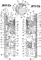
Figur 1a das Schloss in einem Aufbau als selbstverriegelndes Schlossmit abgenommenem Schlossboden 3, wobei der Riegel eine rückgeschlossene Stellung, dieFalle 6 eine unvollständig vorgeschlossene Stellung,eine Steuerfalle 13 eine nicht betätigte Stellung,ein erster Hauptschieber 8 eine Öffnungsstellung,ein Rastkörper 12 eine Blockierstellungund ein Freigabeelement 17 eine Raststellung einnimmt; - Fig. 1b
- das in der
Figur 1a dargestellte Schloss jedoch von der Rückseite hermit abgenommener Schlossdecke 4; - Fig. 2a
- eine Darstellung gemäß
Figur 1a jedoch nach dem Schließen einer mit dem Schloss ausgerüsteten Tür in eine Stellung, in der dieFalle 5 und die Steuerfalle 13 aneinem Schließblech 55 aufgelaufen sind, so dass dieSteuerfalle 13 ihre betätigte Stellung und dieFalle 5 eine zurückverlagerte Stellung einnimmt, der Rastkörper 12 nimmt eine Freigabestellung ein; - Fig. 2b
- eine Darstellung gemäß
Figur 2a jedoch von der Rückseite her; - Fig. 3a
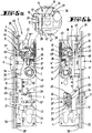
- eine Zwischenstellung in einer Darstellung gemäß
Figur 1a jedoch nach dem vollständigen Schließen der mit dem Schloss ausgestatteten Tür, wobei dieFalle 6 ineine Falleneintrittsöffnung 56 eingetreten ist, aber noch nicht ihre vollständig vorgeschlossene Stellung erreicht hat, so dass der Freigabehebel 17 noch seine Raststellung einnimmt; - Fig. 3b
- eine Darstellung gemäß
Figur 3a jedoch von der Rückseite her; - Fig. 4a
- eine Darstellung gemäß
Figur 1a jedoch mit vollständig vorgeschlossenerFalle 6, wobei ein Fallenschwanz 6' unterhalb eines Rastvorsprungs 12"des Rastkörpers 12 liegt, wobei ferner eine Betätigungsschulter 41 des Fallenschwanzes 6'das Freigabeelement 17 in eine Lösestellung gebracht hat und nachfolgend der Hauptschieber 8von einem Kraftspeicher 10 in eine Zuhaltungsfunktionsstellung verlagert worden ist und derRiegel 5 vorgeschlossen ist; - Fig. 4b
- eine Darstellung gemäß
Figur 4a jedoch von der Rückseite her; - Fig. 5a
- eine weitere Zwischenstellung, nachdem durch Betätigen eines Drückers 7 mit einem Nussarm 7' die
Falle 6 teilweise zurückgeschlossen worden ist,mit einem Nussarm 7"der Hauptschieber 8 angehoben, so dass derRiegel 5 teilweise zurückgeschlossen worden ist und der Hauptschieber 8 durch eine Rastnase 18 des Freigabeelementes in seiner Stellung verrastet ist; - Fig. 5b
- eine Darstellung gemäß
Figur 5a jedoch von der Rückseite her; - Fig. 6a
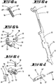
- perspektivisch eine Baueinheit betreffend
den Kraftspeicher 10; - Fig. 6b
- eine erste Explosionsdarstellung einer Baueinheit betreffend
das Freigabeelement 17 undden Rastkörper 12; - Fig. 6c
- eine zweite Explosionsdarstellung der in
Figur 6b dargestellten Baueinheit; - Fig. 6d
- eine Baueinheit betreffend die
Steuerfalle 13; - Fig. 6e
einen Hauptschieber 8 zur Verwendung in einem selbstverriegelnden Schloss;- Fig. 6f
- eine Baueinheit
betreffend ein Halteglied 14mit einem Haltegliedträger 15; - Fig. 6g
einen Antriebsschieber 22;- Fig. 6h
- einen
anders gestalteten Hauptschieber 9 zur Verwendung in einem nicht selbstverriegelnden Schloss; - Fig. 7a
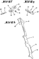
- eine Darstellung gemäß
Figur 1a , bei der das Schloss als nicht selbstverriegelndes Antipanikschloss aufgebaut ist, wobei dieFalle 6 mittels einerNuss 7 teilweise zurückgezogen ist; - Fig. 7b
- eine Darstellung gemäß
Figur 7a jedoch von der Rückseite her; - Fig. 8a
- das
von der Schlossdecke 4 verschlossene Schloss mit Blick auf dieSchlossdecke 4 zur Verdeutlichung der Lage von Befestigungsöffnungen zur Steckbefestigung der Baueinheiten; und - Fig. 8b
das von Schlossboden 3 verschlossene Schloss mit Blick aufden Schlossboden 3 zur Verdeutlichung der Lage von Befestigungsöffnungen zur Steckbefestigung der Baueinheiten.
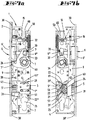
- Fig. 1a
-
Figure 1a the lock in a structure as a self-locking lock with thelock base 3 removed, the bolt having a closed position, thelatch 6 an incompletely pre-locked position, acontrol latch 13 an unactuated position, a firstmain slide 8 an open position, a locking body 12 a blocking position and aRelease element 17 assumes a latching position; - Figure 1b
- that in the
Figure 1a The lock shown, however, from the rear with thelock cover 4 removed; - Fig. 2a
- a representation according to
Figure 1a however, after a door equipped with the lock has been closed into a position in which thelatch 5 and thecontrol latch 13 have run into astrike plate 55, so that thecontrol latch 13 assumes its actuated position and the latch 5 a retracted position, the latchingbody 12 assumes a release position; - Figure 2b
- a representation according to
Figure 2a but from the rear; - Fig. 3a
- an intermediate position in a representation according to
Figure 1a however, after the door equipped with the lock has been completely closed, thelatch 6 having entered alatch entry opening 56, but not yet having reached its fully pre-closed position, so that therelease lever 17 is still in its detent position; - Figure 3b
- a representation according to
Figure 3a but from the rear; - Figure 4a
- a representation according to
Figure 1a but with a completelypre-closed latch 6, with a latch tail 6 'below a latchingprojection 12 "of the latchingbody 12, anactuating shoulder 41 of the latch tail 6' also having brought therelease element 17 into a release position and subsequently themain slide 8 from anenergy store 10 into a Locking function position has been relocated and thebolt 5 is pre-locked; - Figure 4b
- a representation according to
Figure 4a but from the rear; - Figure 5a
- Another intermediate position, after the
latch 6 has been partially closed by actuating apusher 7 with a nut arm 7 ', themain slide 8 is raised with anut arm 7 ″ so that thebolt 5 has been partially closed and themain slide 8 has been closed by adetent 18 the release element is locked in position; - Figure 5b
- a representation according to
Figure 5a but from the rear; - Figure 6a
- in perspective, a structural unit relating to the
energy store 10; - Figure 6b
- a first exploded view of a structural unit relating to the
release element 17 and the latchingbody 12; - Figure 6c
- a second exploded view of the in
Figure 6b assembly shown; - Fig. 6d
- an assembly relating to the
control trap 13; - Figure 6e
- a
main slide 8 for use in a self-locking lock; - Fig. 6f
- an assembly relating to a holding
member 14 with a holdingmember carrier 15; - Fig. 6g
- a
drive slide 22; - Fig. 6h
- a differently designed
main slide 9 for use in a non-self-locking lock; - Figure 7a
- a representation according to
Figure 1a in which the lock is constructed as a non-self-locking anti-panic lock, thelatch 6 being partially retracted by means of anut 7; - Figure 7b
- a representation according to
Figure 7a but from the rear; - Figure 8a
- the lock closed by the
lock cover 4 with a view of thelock cover 4 to illustrate the position of fastening openings for plug-in fastening of the structural units; and - Figure 8b
- the lock closed by the
lock base 3 with a view of thelock base 3 to illustrate the position of the fastening openings for the plug-in fastening of the structural units.
Das in den Zeichnungen dargestellte Schloss ist beispielsweise von Teilen eines Bausatzes derart modulartig aufgebaut, dass es durch den Austausch von einer oder mehreren Baueinheiten entweder als selbstverriegelndes Schloss oder als nicht selbstverriegelndes Schloss aufgebaut werden kann. In beiden Aufbauten besitzt das Schloss bevorzugt eine Antipanikfunktion, bei der durch Betätigen einer Nuss 7 nicht nur eine Falle 6, sondern auch ein Riegel 5 zurückgezogen werden kann, so dass eine mit einem derartigen Schloss ausgestattete Tür durch ledigliche Drückerbetätigung geöffnet werden kann. Sofern das Schloss in einem Aufbau gemäß der
Das in den
Ein zweiter Nussarm 7" greift an einem Mitnehmer 26 eines Hauptschiebers 8 an, um den Hauptschieber 8 von einer Zuhaltungsfunktionsstellung in eine Öffnungsstellung zu verlagern. In der Zuhaltungsfunktionsstellung greift ein Zuhaltungsvorsprung 28 des ersten Hauptschiebers 8 in eine Lageröffnung 29 des Riegelschwanzes 5" ein (
Um den Hauptschieber 8 in der Öffnungsstellung zu halten ist ein Freigabeelement 17 vorgesehen. Das Freigabeelement 17 besitzt die Form eines zweiarmigen Hebels. Am Ende eines ersten Hebelarms befindet sich eine Rastnase 18, die eine Raststufe 19 des Hauptschiebers 8 untergreift. Neben der Raststufe 19 sind zahnartig weitere Raststufen 42 angeordnet. Der zweite Arm des Freigabeelementes 17 bildet einen Betätigungsarm 48 aus, der von einer Betätigungsschulter 41 des Fallenschwanzes 6" beaufschlagt werden kann, wenn die Falle 6 eine vollständig vorgeschlossene Stellung (
Eine Lagerachse 47 des Freigabeelementes 17 ist in einer Lagerbohrung 59 des Lagerkörpers 11 gelagert, der aus Kunststoff besteht und zwischen Schlossdecke 4 und Schlossboden 3 gehalten ist.A bearing
In einer insbesondere weiteren Lageröffnung 29 des Lagerkörpers 11 sitzt ein Rastkörper 12, der die Form eines Rundstiftes mit einem durchmesservergrößerten Kopf 12' besitzt. Das dem Kopf weggewandte Ende des Rastkörper 12 bildet einen Rastvorsprung 12" aus, der in einer Blockierstellung (
Auch der Kraftspeicher 10, der den Hauptschieber 8 beaufschlagt ist eine lösbare Baueinheit. Von einem Lagerbock 45 ragen 2 Befestigungsvorsprünge 45' ab, die in Befestigungsöffnungen 44 von Schlossboden 3 und Schlossdecke 4 stecken. Vom Lagerbock 45 ragt ein Lagerzapfen 46 ab, der eine Wendelgangdruckfeder 58 trägt. Die Wendelgangdruckfeder 58 stützt sich einseitig am Lagerbock 45 und anderseitig an einem Mitnehmer 27 des Hauptschiebers 8 ab. Hierzu durchgreift der Lagerzapfen 46 eine Bohrung des Mitnehmers 27.The
Die Funktionsweise des in den
Ausgehend von einer in den
Während in der in der
Die Linearbewegung des ersten Hauptschiebers 8 wird dabei über ein Übertragungszahnrad 21 auf eine Kurbelanordnung übertragen, mit der der Riegel 5 in die zurückgeschlossene Stellung verlagert wird. Hierzu besitzt der das Übertragungszahnrad 21 und dessen Umfangsverzahnung 21' ausbildende Körper einen Kurbelarm 63 und eine Verzahnung 66, die in eine Gegenverzahnung 65 des Riegels 5 eingreift.The linear movement of the first
Um das Schloss von der in den
- Durch
Betätigen der Drückernuss 7 wird mittels des zweiten Nussarmes 7" der ersteHauptschieber 8 angehoben.Die Verzahnung 24 greift in die Verzahnung 21' des Übertragungszahnrades 21 ein, umden Riegel 5 nach einem Freigang, bei dem der Zuhaltungsvorsprung 28 die Lageröffnung 29 verlässt, zurückzuziehen. Der Nussarm 7' zieht dieFalle 6 zurück. - Durch einen äußeren Druck auf einen Taster 43, der an seinem Ende eine Steuerschräge 43' aufweist, die bei einer Verlagerung des
Tasters 43den Zuhaltungsvorsprung 28 aus der Lageröffnung 29 heraushebt, so dass anschließend derRiegel 5 von außen in die rückgeschlossene Stellung gebracht werden kann. Über das mit der Linearverzahnung 24zusammenwirkende Übertragungszahnrad 21 wird der erste Hauptschieber 8 in eine Öffnungsstellung gebracht. - Durch Drehen eines in eine Schließzylinder-
Einstecköffnung 25 eingesteckten Schließzylinder. Dessen Schließglied greift aneinem Mitnehmer 31 des ersten Hauptschiebers 8 an, um ihn in die Öffnungsstellung zu verlagern.
- By actuating the
handle follower 7, the firstmain slide 8 is raised by means of thesecond follower arm 7 ″. Thetoothing 24 engages in the toothing 21 'of thetransmission gear 21 in order to release thebolt 5 after a clearance in which thetumbler projection 28 leaves thebearing opening 29, The nut arm 7 'pulls thetrap 6 back. - By external pressure on a
button 43, which has a control slope 43 'at its end, which lifts thetumbler projection 28 out of the bearing opening 29 when thebutton 43 is displaced, so that thebolt 5 can then be brought into the closed position from the outside . The firstmain slide 8 is brought into an open position via thetransmission gear 21 cooperating with thelinear toothing 24. - By rotating a lock cylinder inserted into a lock
cylinder insertion opening 25. Its closing element engages adriver 31 of the firstmain slide 8 in order to move it into the open position.
Die
In das so vorbereitete Schloss sind ein Haltegliedträger 15 (vgl.
Der Haltegliedträger 15 ist ein Kunststoffteil, welches sich mit einer auf einem Stift 61 sitzenden Wendelgangfeder 60 an einem Vorsprung im Schlossgehäuse abstützt. Das andere Ende der Wendelgangfeder 60 greift an einem Ende des Haltegliedträgers 15 an. Der Haltegliedträger 15 besitzt einen Zapfen 67, der ein ringförmiges Halteglied 14 trägt. Ein Langloch 51, welches als Lagerauge wirkt, wird von einem Lagerzapfen 52 durchgriffen, der auch ein Langloch 62 des zweiten Hauptschiebers 9 durchgreift.The holding
Der erste Hauptschieber 8 besitzt zwei Rastflanken 16, die eine V-förmige Rastnische ausbilden. In diese Rastnische kann das Halteglied 14 eingreifen, um den ersten Hauptschieber 8 in einer Öffnungsstellung (
Schlossboden 3 und Schlossdecke 4 weisen zudem im Bereich der Schließzylinder-Einstecköffnung 25 einen Führungsschlitz 53 auf, der schräg zur Verlagerungsrichtung des zweiten Hauptschiebers 9, also auch schräg zum Stulp 2 verläuft. In diesem Führungsschlitz 3 steckt jeweils ein Führungszapfen 57 eines in der
In einer nicht dargestellten alternativen Ausgestaltung kann der Schlitz 53 aber auch bogenförmig sein und kann die Verzahnung 23 auch bogenförmig sein.In an alternative embodiment, not shown, the
Die Verzahnung 23 kämmt mit der Umfangsverzahnung 21' des Übertragungszahnrades 21. Da die Umfangsverzahnung 21' auch gleichzeitig mit der Verzahnung 24 des ersten Hauptschiebers 8 kämmt, wird eine Verlagerung des Antriebsschiebers 2 direkt unter Bewegungsumkehr auf den zweiten Hauptschieber 9 übertragen. Der erste Hauptschieber 8 lässt sich somit einerseits durch Angriff des Schließgliedes des Schließzylinders am Mitnehmer 31 in eine Öffnungsstellung verlagern oder durch Angriff des Schließgliedes an der Nase 22" von der Öffnungsstellung in die Zuhaltungsfunktionsstellung verlagern.The
In der Öffnungsstellung wird der erste Hauptschieber 8 durch das Halteglied 14 gehalten. Das Halteglied 14 bildet einen Rastzapfen aus, der in eine Rastnische eingreift, die von den beiden Rastflanken 16 gebildet ist. Die Rastnische wird von zwei im Wesentlichen geradlinig verlaufenden Rastflanken 16 gebildet, die in einem Winkel von größer 90° zueinander stehen. Die Rastnische öffnet sich einer vom Stulp 2 wegweisenden Richtung.In the open position, the first
Das Öffnen des Schlosses erfolgt in der oben beschriebenen Weise, entweder durch Drehen der Drückernuss 7, durch externe Beaufschlagung des Tasters 43 und des Riegels 5 oder durch die Betätigung eines Schließzylinders.The lock is opened in the manner described above, either by turning the
Die vorstehenden Ausführungen dienen der Erläuterung der von der Anmeldung insgesamt erfassten Erfindungen, die den Stand der Technik zumindest durch die folgenden Merkmalskombinationen jeweils auch eigenständig weiterbilden, wobei zwei, mehrere oder alle dieser Merkmalskombinationen auch kombiniert sein können, nämlich:The above explanations serve to explain the inventions covered by the application as a whole, which also develop the state of the art independently at least through the following combinations of features, whereby two, more or all of these combinations of features can also be combined, namely:
Ein Schloss, das dadurch gekennzeichnet ist, dass das Schloss durch Ergänzen zumindest eines am Hauptschieber 8, 9 angreifenden Kraftspeichers 10, eines die Falle 6 in einer unvollständig vorgeschlossen Stellung haltenden Rastelementes 12, einer Steuerfalle 13, die in einer betätigten Stellung das Rastelement 12 zur Verlagerung in eine Freigabestellung freigibt, in der die Falle 6 von ihrer unvollständig vorgeschlossen Stellung in eine vollständig vorgeschlossen Stellung ausfährt, eines den Hauptschieber 8, 9 in der Öffnungsstellung haltendes Freigabeelement 17, das von der Falle 6 bei ihrer Verlagerung von der unvollständig vorgeschlossen Stellung in die vollständig vorgeschlossen Stellung von einer Raststellung in eine Lösestellung gebracht wird, zu einem selbstverriegelnden Schloss veränderbar ist, bei dem der sich entspannende Kraftspeicher 10 den Hauptschieber 8, 9 in seine Öffnungsstellung verlagert.A lock, which is characterized in that the lock is activated by adding at least one
Ein Schloss, das gekennzeichnet ist durch ein im Gehäuse 1 befestigtes Halteglied 14, das mit einem Gegenhalteglied 16 des Hauptschiebers 9 zusammenwirkt, um den Hauptschieber 9 in der zweiten Stellung zu halten, wobei das Halteglied 14 und das Gegenhalteglied 16 durch Überwinden einer Rastkraft zum Verlagern des Hauptschiebers 9 in die erste Stellung voneinander trennbar sind.A lock, which is characterized by a holding
Ein Schloss, das gekennzeichnet ist durch einen eine geradlinige Verzahnung aufweisenden Antriebsschieber 22, der mit einer Umfangsverzahnung 21' eines Übertragungszahnrades 21 kämmt, wobei eine Verlagerung des Antriebsschiebers 22 eine Drehung des Übertragungszahnrades 21 und eine davon abgeleitete Verlagerung des Riegels 5 und des Hauptschiebers 9 bewirkt.A lock which is characterized by a
Ein Schloss, das dadurch gekennzeichnet ist, dass das Freigabeelement 17 ein Schwenkhebel ist, der in seiner Raststellung mit einer Rastnase 18 eine Raststufe 19 des Hauptschiebers 8 untergreift und von einer Betätigungsschulter 41 der Falle 6 in die Lösestellung gebracht wird.A lock, which is characterized in that the
Ein Schloss, das dadurch gekennzeichnet ist, dass das Rastelement 12 ein in einer Lageröffnung 29 eines am Gehäuse 1 befestigten Lagerkörpers 11 gelagerter parallel zur Verlagerungsrichtung des Hauptschiebers 8 verlagerbarer Rastkörper 12 ist.A lock which is characterized in that the latching
Ein Schloss, das dadurch gekennzeichnet ist, dass Schlossboden 3 und Schlossdecke 4 jeweils eine Befestigungsöffnung 44 aufweisen, in die Befestigungsvorsprünge 45' eines vom Kraftspeicher 10 ausgebildeten, lösbar am Gehäuse 1 befestigten Lagerbocks 45 eingreifen.A lock, which is characterized in that the
Ein Schloss, das dadurch gekennzeichnet ist, dass der Lagerbock 45 eine Druckfeder 58 trägt, die sich an einem Mitnehmer 27 des Hauptschiebers 8 abstützt, der eine Öffnung aufweist, durch die ein am Lagerbock 45 befestigter Lagerzapfen 46 ragt, der die Druckfeder durchgreift.A lock, which is characterized in that the bearing
Ein Schloss, das dadurch gekennzeichnet ist, dass das Rastelement 12 ein in einer Lageröffnung 29 eines lösbar am Gehäuse 1 befestigten Lagerkörpers 11 gelagerter, parallel zur Verlagerungsrichtung des Hauptschiebers 8 verlagerbarer Rastkörper ist, wobei insbesondere vorgesehen ist, dass der Lagerkörper 11 ein aus Kunststoff gefertigtes Einsatzstück ist, welches zwischen Schlossboden 3 und Schlossdecke 4 gehalten ist.A lock, which is characterized in that the latching
Ein Schloss, das dadurch gekennzeichnet ist, dass das Rastelement 12 ein einen Kopf 12' und einen Rastvorsprung 12" aufweisender Stift ist, der in Richtung auf eine Stützfläche 37 der Steuerfalle 13 von einem Federelement 35 federkraftbeaufschlagt ist.A lock which is characterized in that the latching
Ein Schloss, das dadurch gekennzeichnet ist, dass der Stützfläche 37 eine Steuerschräge 36 benachbart ist, welche bei einer Vorverlagerung der Steuerfalle 13 den Kopf 12' beaufschlagt, um den Rastkörper 12 von seiner Freigabestellung in seine die vollständige Vorverlagerung der Falle 6 hemmende Blockierstellung zu verlagern.A lock, which is characterized in that the
Ein Schloss, das dadurch gekennzeichnet ist, dass sich die den Kopf 12' des Rastelementes 12 beaufschlagende Druckfeder 35 an einer Stufe der Lageröffnung 29 abstützt.A lock which is characterized in that the
Ein Schloss, das dadurch gekennzeichnet ist, dass zur Veränderung des Schlosses zu einem selbstverriegelnden Schloss ein erster Hauptschieber 8 gegen einen zweiten Hauptschieber 9 ausgetauscht wird und/oder dass der Kraftspeicher 10, ein Lagerkörper 11 zur Lagerung des Rastelementes 12 und des Freigabeelementes 17 durch in Öffnungen 44, 70, 70' eingreifende Vorsprünge 45', 69, 69' lösbar am Gehäuse 1 befestigt sind und/oder dass sämtliche zum Verändern des Schlosses zu einem selbstverriegelnden Schloss zu ergänzenden oder auszutauschenden Bauteilen lösbar durch Formschlusseingriffsmittel 69, 69', 45', 67, 70, 70' mit dem Gehäuse 1 verbunden sind.A lock, which is characterized in that, to change the lock to a self-locking lock, a first
Ein Schloss, das dadurch gekennzeichnet ist, dass das Freigabeelement 17 ein Schwenkhebel ist, der in seiner Raststellung mit einer Rastnase 18 eine Raststufe 19 des Hauptschiebers 8 untergreift und von einer Betätigungsschulter 41 der Falle 6 in die Lösestellung gebracht wird.A lock, which is characterized in that the
Ein Schloss, das dadurch gekennzeichnet ist, dass das Freigabeelement 17 einen Betätigungsarm 48 aufweist, der von einer Betätigungsschulter 41 des Fallenschwanzes 6" beaufschlagt wird.A lock which is characterized in that the
Ein Schloss, das dadurch gekennzeichnet ist, dass das Freigabeelement 17 von einem Federelement 49 in einer die Raststufe 19 des Hauptschiebers 9 untergreifende Stellung beaufschlagt wird.A lock, which is characterized in that the
Ein Schloss, das dadurch gekennzeichnet ist, dass der Raststufe 19 ein oder mehrere als Hilfsraststufen wirkende Zähne 42 benachbart sind.A lock which is characterized in that one or
Ein Schloss, das dadurch gekennzeichnet ist, dass der Lagerkörper 11 eine Lagerbohrung 59 zur Lagerung der Lagerachse 47 des Freigabeelementes und/oder zwei senkrecht und versetzt zueinander angeordnete Lagerbohrungen 29, 59 und/oder eine Stützschulter für ein das Freigabeelement 17 beaufschlagendes Federelement 49 ausbildet.A lock, which is characterized in that the bearing
Ein Schloss, das gekennzeichnet ist durch ein im Gehäuse 1 befestigtes Halteglied 14, das mit einem Gegenhalteglied 16 des Hauptschiebers 9 zusammenwirkt, um den Hauptschieber 9 in der zweiten Stellung zu halten, wobei das Halteglied 14 und das Gegenhalteglied 16 durch Überwinden einer Rastkraft zum Verlagern des Hauptschiebers 9 in die erste Stellung voneinander trennbar sind.A lock, which is characterized by a holding
Ein Schloss, das dadurch gekennzeichnet ist, dass das Halteglied 14 ein in Richtung quer zur Verlagerungsrichtung des Hauptschiebers 9 gegen die Rückstellkraft eines Federelementes 60 verlagerbarer Rastzapfen ist, der in der Freigabestellung des Hauptschiebers 9 in einer vom Gegenhalteglied 16 gebildeten Rastnische einliegt.A lock, which is characterized in that the holding
Ein Schloss, das dadurch gekennzeichnet ist, dass die Rastnische von zwei Schrägflächen ausgebildet ist.A lock, which is characterized in that the locking niche is formed by two inclined surfaces.
Ein Schloss, das dadurch gekennzeichnet ist, dass das Halteglied 14 auf einem zwischen Schlossboden 3 und Schlossdecke 4 in Richtung quer zur Verlagerungsrichtung des Hauptschiebers 9 verlagerbaren Haltegliedträger 15 sitzt.A lock, which is characterized in that the holding
Ein Schloss, das dadurch gekennzeichnet ist, dass sich das Federelement 60 an einem zwischen Schlossboden 3 und Schlossdecke 4 gehaltenem Böckchen 50 abstützt, und/oder, dass der Haltegliedträger 15, das Federelement 60 und ein das Federelement 60 widerlagerndes Böckchen 50 lediglich durch lösbar in Befestigungsöffnungen der Schlossdecke 44 und des Schlossbodens 3 steckenden Haltevorsprüngen 64 im Gehäuse 1 fixiert sind und/oder dass ein längliches Lagerauge 51 des Haltegliedträgers 15 von einem Lagerzapfen 52 durchgriffen ist, welcher Lagerzapfen 52 auch ein Langloch 62 des Hauptschiebers 9 durchgreift und/oder dass der Haltegliedträger 15 ein Kunststoffspritzgussteil ist.A lock, which is characterized in that the
Ein Schloss, das dadurch gekennzeichnet ist, dass ein mit einer Umfangsverzahnung 21' eines Übertragungszahnrades 21 kämmender Antriebsschieber 22 lösbar in einem schräg zur Verlagerungsrichtung des Hauptschiebers 8, 9 verlaufenden Führungsschlitz 53 des Schlossbodens 3 und/oder der Schlossdecke 4 geführt ist.A lock, which is characterized in that a
Ein Schloss, das dadurch gekennzeichnet ist, dass das Übertragungszahnrad 21 in eine Linearverzahnung 24 des Hauptschiebers 8, 9 eingreift und/oder dass der Antriebsschieber 22 einen geradlinig verlaufenden Rücken 22' aufweist, der sich an einem gehäusefesten Stützzapfen 54 abstützt und/oder dass der Antriebsschieber 22 eine Nase 22" aufweist, die vom Schließglied eines Schließzylinders beaufschlagbar ist.A lock, which is characterized in that the
Ein Schloss, das dadurch gekennzeichnet ist, dass das Übertragungszahnrad 21 eine Kurbelarm 63 und/oder eine Verzahnung 26 aufweist, um den Riegel 5 in einer Richtung quer zur Verlagerungsrichtung des Hauptschiebers 8, 9 zu verlagern.A lock, which is characterized in that the
Ein Schloss, das dadurch gekennzeichnet ist, dass die erste Stellung des Hauptschiebers 8, 9 eine eine Verlagerung des Riegels 5 verhindernde Zuhaltungsfunktionsstellung ist und/oder dass die zweite Stellung des Hauptschiebers 8, 9 eine Öffnungsstellung ist, in der eine das Schloss aufweisende Tür durch lediglich einen Rückzug der Falle 6 geöffnet werden kann.A lock which is characterized in that the first position of the
Einen Bausatz für ein Schloss mit einem von einer rückgeschlossenen Stellung in eine vorgeschlossene Stellung aus einem Gehäuse 1 herausfahrbaren Riegel 5, mit einer im Gehäuse 1 drehbar gelagerten Nuss 7 zum Zurückziehen einer mittels eines Federelementes 20 in eine vorgeschlossene Stellung beaufschlagten Falle 6 in eine zurückgezogene Stellung, mit einem ersten Hauptschieber 8, der in der vorgeschlossenen Stellung des Riegels 5 eine erste Stellung einnimmt und der bei einer Drehung der Nuss 7 zum Zurückziehen der Falle 6 von einem Betätigungselement 7" unter Verlassen der ersten Stellung und Mitnahme des Riegels 5 in seine zurückgeschlossene Stellung in eine zweite Öffnungsstellung verlagerbar ist, mit einem lösbar am Schlossgehäuse 1 befestigbaren Kraftspeicher 10 zur Beaufschlagung des Hauptschiebers 8, 9 von der zweiten Stellung in die erste Stellung, mit einer Steuerfalle 13, mit einem Lagerkörper 11, der ein Rastelement 12 und ein Freigabeelement 17 lagert und lösbar am Schlossgehäuse 1 befestigbar ist, einem Haltegliedträger 15, das ein Halteglied 14 trägt und lösbar am Schlossgehäuse 1 befestigbar ist, und einem zweiten Hauptschieber 9, der gegen den ersten Hauptschieber 8 austauschbar ist.A construction kit for a lock with a
Alle offenbarten Merkmale sind (für sich, aber auch in Kombination untereinander) erfindungswesentlich. In die Offenbarung der Anmeldung wird hiermit auch der Offenbarungsinhalt der zugehörigen/beigefügten Prioritätsunterlagen (Abschrift der Voranmeldung) vollinhaltlich mit einbezogen, auch zu dem Zweck, Merkmale dieser Unterlagen in Ansprüche vorliegender Anmeldung mit aufzunehmen. Die Unteransprüche charakterisieren, auch ohne die Merkmale eines in Bezug genommenen Anspruchs, mit ihren Merkmalen eigenständige erfinderische Weiterbildungen des Standes der Technik, insbesondere um auf Basis dieser Ansprüche Teilanmeldungen vorzunehmen. Die in jedem Anspruch angegebene Erfindung kann zusätzlich ein oder mehrere der in der vorstehenden Beschreibung, insbesondere mit Bezugsziffern versehene und/oder in der Bezugsziffernliste angegebene Merkmale aufweisen. Die Erfindung betrifft auch Gestaltungsformen, bei denen einzelne der in der vorstehenden Beschreibung genannten Merkmale nicht verwirklicht sind, insbesondere soweit sie erkennbar für den jeweiligen Verwendungszweck entbehrlich sind oder durch andere technisch gleichwirkende Mittel ersetzt werden können.
Claims (15)
der in der vorgeschlossenen Stellung des Riegels (5) eine erste Stellung einnimmt,
aus der er durch Angriff eines Schließgliedes des Schließzylinders bei dessen Drehung an einem Mitnehmer (31) des Hauptschiebers (8, 9) unter Mitnahme des Riegels (5) in seine rückgeschlossene Stellung in eine zweite Stellung verlagerbar ist,
aus der er durch Angriff des Schließgliedes bei dessen Drehung in Gegenrichtung zurück in die erste Stellung verlagerbar ist, gekennzeichnet durch einen eine mit der Umfangsverzahnung (21') kämmende Verzahnung (23) aufweisenden Antriebsschieber (22),
der eine Nase (22") aufweist, die vom Schließglied bei der Drehung in Gegenrichtung beaufschlagt wird.Lock with a bolt (5) that can be displaced by turning a lock cylinder between a closed position and a pre-locked position moved out of a housing (1) and with a bolt (5) arranged in the housing (1) and one with circumferential toothing (21 ') of a transmission gear (21) ) meshing teeth (24) having main slide (8, 9),
which assumes a first position in the pre-locked position of the bolt (5),
from which it can be displaced into its closed position in a second position by engaging a locking member of the locking cylinder when it rotates on a driver (31) of the main slide (8, 9) while driving the bolt (5),
from which it can be displaced back into the first position by engagement of the closing element when it rotates in the opposite direction, characterized by a drive slide (22) which has a toothing (23) meshing with the circumferential toothing (21 '),
which has a nose (22 ") which is acted upon by the closing element when it rotates in the opposite direction.
Applications Claiming Priority (1)
| Application Number | Priority Date | Filing Date | Title |
|---|---|---|---|
| DE102019125144.3A DE102019125144A1 (en) | 2019-09-18 | 2019-09-18 | Modular lock with anti-panic function |
Publications (4)
| Publication Number | Publication Date |
|---|---|
| EP3805493A2 true EP3805493A2 (en) | 2021-04-14 |
| EP3805493A3 EP3805493A3 (en) | 2021-07-14 |
| EP3805493C0 EP3805493C0 (en) | 2023-08-09 |
| EP3805493B1 EP3805493B1 (en) | 2023-08-09 |
Family
ID=72474232
Family Applications (1)
| Application Number | Title | Priority Date | Filing Date |
|---|---|---|---|
| EP20195952.5A Active EP3805493B1 (en) | 2019-09-18 | 2020-09-14 | Modular lock with panic function |
Country Status (3)
| Country | Link |
|---|---|
| EP (1) | EP3805493B1 (en) |
| DE (1) | DE102019125144A1 (en) |
| PL (1) | PL3805493T3 (en) |
Families Citing this family (2)
| Publication number | Priority date | Publication date | Assignee | Title |
|---|---|---|---|---|
| DE102021109071A1 (en) | 2021-04-12 | 2022-10-13 | WILKA Schließtechnik GmbH | Electrical opener for a door lock |
| DE102021118229A1 (en) | 2021-07-14 | 2023-01-19 | WILKA Schließtechnik GmbH | Lock with latch lockable in a retracted position |
Citations (3)
| Publication number | Priority date | Publication date | Assignee | Title |
|---|---|---|---|---|
| DE19905597C2 (en) | 1999-02-11 | 2002-07-18 | Wilka Schliestechnik Gmbh | panic lock |
| DE102004013646A1 (en) | 2004-03-12 | 2005-09-29 | Wilka Schließtechnik GmbH | Emergency exit lock for building has spring moving bolt withdrawal lever connected to sliding bolt and includes force transmission lever |
| DE102012111526A1 (en) | 2012-11-28 | 2014-05-28 | Wilka Schließtechnik GmbH | Tubular frame lock structure for door, has blocking element that is provided to block the displacement of aperture element in actuating position, and bolt which is inserted into opening |
Family Cites Families (6)
| Publication number | Priority date | Publication date | Assignee | Title |
|---|---|---|---|---|
| IT1284465B1 (en) * | 1996-07-04 | 1998-05-21 | Welka Serrature Spa | LOCK FOR ONE DOOR AND SIMILAR |
| CH694970A5 (en) * | 2000-04-19 | 2005-10-14 | Glutz Ag | Selectively operable door lock permits operating of bolt with key or door handle and has mechanism connecting lock tumbler and bolt, permitting displacement of door handle |
| BE1020811A3 (en) * | 2012-05-07 | 2014-05-06 | Parys Remi E Van | PANIC LOCK. |
| EP3045623B1 (en) * | 2015-01-19 | 2020-02-19 | ASSA ABLOY (Schweiz) AG | Safety device for a door |
| DE102016118119A1 (en) * | 2016-09-26 | 2018-03-29 | Assa Abloy (Schweiz) Ag | Modular castle |
| AT16382U1 (en) * | 2017-11-08 | 2019-08-15 | Roto Frank Ag | lock |
-
2019
- 2019-09-18 DE DE102019125144.3A patent/DE102019125144A1/en active Pending
-
2020
- 2020-09-14 PL PL20195952.5T patent/PL3805493T3/en unknown
- 2020-09-14 EP EP20195952.5A patent/EP3805493B1/en active Active
Patent Citations (3)
| Publication number | Priority date | Publication date | Assignee | Title |
|---|---|---|---|---|
| DE19905597C2 (en) | 1999-02-11 | 2002-07-18 | Wilka Schliestechnik Gmbh | panic lock |
| DE102004013646A1 (en) | 2004-03-12 | 2005-09-29 | Wilka Schließtechnik GmbH | Emergency exit lock for building has spring moving bolt withdrawal lever connected to sliding bolt and includes force transmission lever |
| DE102012111526A1 (en) | 2012-11-28 | 2014-05-28 | Wilka Schließtechnik GmbH | Tubular frame lock structure for door, has blocking element that is provided to block the displacement of aperture element in actuating position, and bolt which is inserted into opening |
Also Published As
| Publication number | Publication date |
|---|---|
| EP3805493C0 (en) | 2023-08-09 |
| EP3805493B1 (en) | 2023-08-09 |
| PL3805493T3 (en) | 2024-03-11 |
| EP3805493A3 (en) | 2021-07-14 |
| DE102019125144A1 (en) | 2021-03-18 |
Similar Documents
| Publication | Publication Date | Title |
|---|---|---|
| EP1932989B1 (en) | Locking device for doors, windows or similar, in particular an espagnolette lock with panic function and multi-point locking | |
| DE60127350T2 (en) | Lock with internal clutch | |
| DE4324300C2 (en) | Anti-panic door lock | |
| EP2951368B1 (en) | Panic lock | |
| EP1574644A2 (en) | Locking system for doors, windows or similar, in particular espagnolette lock with anti-panic function and multiple lock points | |
| EP3805493A2 (en) | Modular lock with panic function | |
| EP0653535B1 (en) | Lock | |
| DE102012111881A1 (en) | Motor operable stationary wing lock for double swing door, has trap ejector and latch ejector that are utilized for shifting terminal slider against opening direction of non-functional position that is brought into functional position | |
| DE4114007C2 (en) | Espagnolette lock | |
| EP2339096B1 (en) | Connecting rod lock with panic function and multiple locking | |
| DE102015000606A1 (en) | Locking device for a pivotally mounted wing | |
| EP3907357A1 (en) | Locking device | |
| EP2562335B1 (en) | Automatic lock | |
| DE19653611B4 (en) | Lock with latch and latch | |
| DE102009051432A1 (en) | Motor vehicle door lock, has locking mechanism and locking lever, where locking mechanism in its open state blocks locking lever | |
| DE3931101A1 (en) | Automatic lock for door - extends bolt automatically on entering lock plate | |
| EP1672153B1 (en) | Lock with dead bolt and dead bolt actuating device | |
| EP0853177B1 (en) | Key and handle follower operated lock with deadbolt and latchbolt | |
| EP3628801A1 (en) | Lock device for a door | |
| AT406496B (en) | MULTI-LOCK LOCK | |
| DE102013111467A1 (en) | Multi Castle | |
| DE102020205673B3 (en) | Self-locking lock | |
| EP1455041B1 (en) | Lock with drive bar and dogging device. | |
| EP3363970B1 (en) | Lock | |
| EP4353928A2 (en) | Lock with energy converter |
Legal Events
| Date | Code | Title | Description |
|---|---|---|---|
| PUAI | Public reference made under article 153(3) epc to a published international application that has entered the european phase |
Free format text: ORIGINAL CODE: 0009012 |
|
| STAA | Information on the status of an ep patent application or granted ep patent |
Free format text: STATUS: THE APPLICATION HAS BEEN PUBLISHED |
|
| AK | Designated contracting states |
Kind code of ref document: A2 Designated state(s): AL AT BE BG CH CY CZ DE DK EE ES FI FR GB GR HR HU IE IS IT LI LT LU LV MC MK MT NL NO PL PT RO RS SE SI SK SM TR |
|
| AX | Request for extension of the european patent |
Extension state: BA ME |
|
| PUAL | Search report despatched |
Free format text: ORIGINAL CODE: 0009013 |
|
| AK | Designated contracting states |
Kind code of ref document: A3 Designated state(s): AL AT BE BG CH CY CZ DE DK EE ES FI FR GB GR HR HU IE IS IT LI LT LU LV MC MK MT NL NO PL PT RO RS SE SI SK SM TR |
|
| RIC1 | Information provided on ipc code assigned before grant |
Ipc: E05B 59/00 20060101AFI20210604BHEP Ipc: E05B 63/20 20060101ALI20210604BHEP Ipc: E05B 65/10 20060101ALI20210604BHEP |
|
| STAA | Information on the status of an ep patent application or granted ep patent |
Free format text: STATUS: REQUEST FOR EXAMINATION WAS MADE |
|
| 17P | Request for examination filed |
Effective date: 20211221 |
|
| RBV | Designated contracting states (corrected) |
Designated state(s): AL AT BE BG CH CY CZ DE DK EE ES FI FR GB GR HR HU IE IS IT LI LT LU LV MC MK MT NL NO PL PT RO RS SE SI SK SM TR |
|
| GRAP | Despatch of communication of intention to grant a patent |
Free format text: ORIGINAL CODE: EPIDOSNIGR1 |
|
| STAA | Information on the status of an ep patent application or granted ep patent |
Free format text: STATUS: GRANT OF PATENT IS INTENDED |
|
| INTG | Intention to grant announced |
Effective date: 20220513 |
|
| RIN1 | Information on inventor provided before grant (corrected) |
Inventor name: BLECKMANN, JOERG Inventor name: HEUER, STEFAN |
|
| GRAJ | Information related to disapproval of communication of intention to grant by the applicant or resumption of examination proceedings by the epo deleted |
Free format text: ORIGINAL CODE: EPIDOSDIGR1 |
|
| STAA | Information on the status of an ep patent application or granted ep patent |
Free format text: STATUS: REQUEST FOR EXAMINATION WAS MADE |
|
| INTC | Intention to grant announced (deleted) | ||
| GRAP | Despatch of communication of intention to grant a patent |
Free format text: ORIGINAL CODE: EPIDOSNIGR1 |
|
| STAA | Information on the status of an ep patent application or granted ep patent |
Free format text: STATUS: GRANT OF PATENT IS INTENDED |
|
| INTG | Intention to grant announced |
Effective date: 20230105 |
|
| GRAS | Grant fee paid |
Free format text: ORIGINAL CODE: EPIDOSNIGR3 |
|
| GRAA | (expected) grant |
Free format text: ORIGINAL CODE: 0009210 |
|
| STAA | Information on the status of an ep patent application or granted ep patent |
Free format text: STATUS: THE PATENT HAS BEEN GRANTED |
|
| APBM | Appeal reference recorded |
Free format text: ORIGINAL CODE: EPIDOSNREFNO |
|
| PUAC | Information related to the publication of a b1 document modified or deleted |
Free format text: ORIGINAL CODE: 0009299EPPU |
|
| STAA | Information on the status of an ep patent application or granted ep patent |
Free format text: STATUS: GRANT OF PATENT IS INTENDED |
|
| AK | Designated contracting states |
Kind code of ref document: B1 Designated state(s): AL AT BE BG CH CY CZ DE DK EE ES FI FR GB GR HR HU IE IS IT LI LT LU LV MC MK MT NL NO PL PT RO RS SE SI SK SM TR |
|
| REG | Reference to a national code |
Ref country code: GB Ref legal event code: FG4D Free format text: NOT ENGLISH |
|
| REG | Reference to a national code |
Ref country code: AT Ref legal event code: REF Ref document number: 1566825 Country of ref document: AT Kind code of ref document: T Effective date: 20230515 |
|
| REG | Reference to a national code |
Ref country code: DE Ref legal event code: R096 Ref document number: 502020003232 Country of ref document: DE |
|
| DB1 | Publication of patent cancelled |
Effective date: 20230428 |
|
| REG | Reference to a national code |
Ref country code: IE Ref legal event code: FG4D Free format text: LANGUAGE OF EP DOCUMENT: GERMAN Ref country code: DE Ref legal event code: R107 Ref document number: 502020003232 Country of ref document: DE |
|
| APAF | Appeal reference modified |
Free format text: ORIGINAL CODE: EPIDOSCREFNE |
|
| GRAA | (expected) grant |
Free format text: ORIGINAL CODE: 0009210 |
|
| STAA | Information on the status of an ep patent application or granted ep patent |
Free format text: STATUS: THE PATENT HAS BEEN GRANTED |
|
| REG | Reference to a national code |
Ref country code: AT Ref legal event code: REZ Ref document number: 1566825 Country of ref document: AT Kind code of ref document: T Effective date: 20230510 |
|
| AK | Designated contracting states |
Kind code of ref document: B1 Designated state(s): AL AT BE BG CH CY CZ DE DK EE ES FI FR GB GR HR HU IE IS IT LI LT LU LV MC MK MT NL NO PL PT RO RS SE SI SK SM TR |
|
| REG | Reference to a national code |
Ref country code: CH Ref legal event code: EP |
|
| REG | Reference to a national code |
Ref country code: DE Ref legal event code: R096 Ref document number: 502020003232 Country of ref document: DE |
|
| U01 | Request for unitary effect filed |
Effective date: 20230818 |
|
| U07 | Unitary effect registered |
Designated state(s): AT BE BG DE DK EE FI FR IT LT LU LV MT NL PT SE SI Effective date: 20230824 |
|
| U20 | Renewal fee paid [unitary effect] |
Year of fee payment: 4 Effective date: 20230905 |
|
| PG25 | Lapsed in a contracting state [announced via postgrant information from national office to epo] |
Ref country code: NO Free format text: LAPSE BECAUSE OF FAILURE TO SUBMIT A TRANSLATION OF THE DESCRIPTION OR TO PAY THE FEE WITHIN THE PRESCRIBED TIME-LIMIT Effective date: 20230810 |
|
| PG25 | Lapsed in a contracting state [announced via postgrant information from national office to epo] |
Ref country code: IS Free format text: LAPSE BECAUSE OF FAILURE TO SUBMIT A TRANSLATION OF THE DESCRIPTION OR TO PAY THE FEE WITHIN THE PRESCRIBED TIME-LIMIT Effective date: 20230910 Ref country code: GR Free format text: LAPSE BECAUSE OF FAILURE TO SUBMIT A TRANSLATION OF THE DESCRIPTION OR TO PAY THE FEE WITHIN THE PRESCRIBED TIME-LIMIT Effective date: 20230811 |
|
| PG25 | Lapsed in a contracting state [announced via postgrant information from national office to epo] |
Ref country code: RS Free format text: LAPSE BECAUSE OF FAILURE TO SUBMIT A TRANSLATION OF THE DESCRIPTION OR TO PAY THE FEE WITHIN THE PRESCRIBED TIME-LIMIT Effective date: 20230809 Ref country code: NO Free format text: LAPSE BECAUSE OF FAILURE TO SUBMIT A TRANSLATION OF THE DESCRIPTION OR TO PAY THE FEE WITHIN THE PRESCRIBED TIME-LIMIT Effective date: 20231109 Ref country code: HR Free format text: LAPSE BECAUSE OF FAILURE TO SUBMIT A TRANSLATION OF THE DESCRIPTION OR TO PAY THE FEE WITHIN THE PRESCRIBED TIME-LIMIT Effective date: 20230809 |
|
| PGFP | Annual fee paid to national office [announced via postgrant information from national office to epo] |
Ref country code: CH Payment date: 20231001 Year of fee payment: 4 |