EP1455041B1 - Lock with drive bar and dogging device. - Google Patents
Lock with drive bar and dogging device. Download PDFInfo
- Publication number
- EP1455041B1 EP1455041B1 EP04100897A EP04100897A EP1455041B1 EP 1455041 B1 EP1455041 B1 EP 1455041B1 EP 04100897 A EP04100897 A EP 04100897A EP 04100897 A EP04100897 A EP 04100897A EP 1455041 B1 EP1455041 B1 EP 1455041B1
- Authority
- EP
- European Patent Office
- Prior art keywords
- lock
- push rod
- shoulder
- lever
- bolt
- Prior art date
- Legal status (The legal status is an assumption and is not a legal conclusion. Google has not performed a legal analysis and makes no representation as to the accuracy of the status listed.)
- Expired - Fee Related
Links
Images


Classifications
-
- E—FIXED CONSTRUCTIONS
- E05—LOCKS; KEYS; WINDOW OR DOOR FITTINGS; SAFES
- E05C—BOLTS OR FASTENING DEVICES FOR WINGS, SPECIALLY FOR DOORS OR WINDOWS
- E05C9/00—Arrangements of simultaneously actuated bolts or other securing devices at well-separated positions on the same wing
- E05C9/02—Arrangements of simultaneously actuated bolts or other securing devices at well-separated positions on the same wing with one sliding bar for fastening when moved in one direction and unfastening when moved in opposite direction; with two sliding bars moved in the same direction when fastening or unfastening
- E05C9/021—Arrangements of simultaneously actuated bolts or other securing devices at well-separated positions on the same wing with one sliding bar for fastening when moved in one direction and unfastening when moved in opposite direction; with two sliding bars moved in the same direction when fastening or unfastening with rack and pinion mechanism
- E05C9/023—Arrangements of simultaneously actuated bolts or other securing devices at well-separated positions on the same wing with one sliding bar for fastening when moved in one direction and unfastening when moved in opposite direction; with two sliding bars moved in the same direction when fastening or unfastening with rack and pinion mechanism between a lock cylinder and the bar
-
- E—FIXED CONSTRUCTIONS
- E05—LOCKS; KEYS; WINDOW OR DOOR FITTINGS; SAFES
- E05C—BOLTS OR FASTENING DEVICES FOR WINGS, SPECIALLY FOR DOORS OR WINDOWS
- E05C9/00—Arrangements of simultaneously actuated bolts or other securing devices at well-separated positions on the same wing
- E05C9/02—Arrangements of simultaneously actuated bolts or other securing devices at well-separated positions on the same wing with one sliding bar for fastening when moved in one direction and unfastening when moved in opposite direction; with two sliding bars moved in the same direction when fastening or unfastening
- E05C9/025—Arrangements of simultaneously actuated bolts or other securing devices at well-separated positions on the same wing with one sliding bar for fastening when moved in one direction and unfastening when moved in opposite direction; with two sliding bars moved in the same direction when fastening or unfastening with pins engaging slots
-
- E—FIXED CONSTRUCTIONS
- E05—LOCKS; KEYS; WINDOW OR DOOR FITTINGS; SAFES
- E05B—LOCKS; ACCESSORIES THEREFOR; HANDCUFFS
- E05B17/00—Accessories in connection with locks
- E05B17/007—Devices for reducing friction between lock parts
-
- E—FIXED CONSTRUCTIONS
- E05—LOCKS; KEYS; WINDOW OR DOOR FITTINGS; SAFES
- E05B—LOCKS; ACCESSORIES THEREFOR; HANDCUFFS
- E05B59/00—Locks with latches separate from the lock-bolts or with a plurality of latches or lock-bolts
Definitions
- the invention relates to a multi-bolt lock with at least one push rod and a holding device for the push rod of the multi-bolt lock to prevent a particular vibration-related displacement relative to engagement elements of a lock mechanism.
- multi-bolt lock To lock a multi-bolt lock, additional bolts are pushed by means of push rods in a blocking position or withdrawn from the locked position. In the unlocked state, the multi-bolt lock is particularly vulnerable to shock and shock, as the push rods can easily get out of sync with a gear transmission.
- multi-bolt locks is noticeable in a version as a panic lock.
- the lock on one side of the door leaf has a knob and on the second via a pusher, the locked lock can be unlocked in a so-called panic situation by a handle operation.
- a freewheeling cylinder is provided, which is rotated by a lock gear during the handle operation. The cylinder is thus not actuated by a key, but by the pusher via a gear or taken.
- the additional bolt unintentionally extend from the lock due to shocks and the weight of the push rods, as the freewheel cylinder can be rotated in this situation, without key operation.
- Known holding devices for push rods in windows and doors include, for example, an elastic plastic part, which counteracts relative movements between push rods and floor damping.
- a disadvantage of these constructions, however, is that the holding forces achieved are too low and the push rods can still get out of sync.
- DE 3 605 826 A1 discloses a lock wherein a spring tongue with a slight kink also has a holding effect on a push rod. It connects with the spring tongue to the kink a sliding area.
- a spring clip 61 is provided which has the effect of a ball catch.
- DE 299 20 508 U1 a vertically acting on the espagnolette slide spring-loaded hook. This slides under spring force on the espagnolette slide and snaps behind an edge thereof to hold the push rod.
- the invention aims to provide the multi-bolt lock with an alternative holding device.
- a multi-bolt lock with the features of claim 1.
- the push rod and / or the push rod slide is associated with a spring-loaded lever having a control surface with a particular recessed holding portion for frictional engagement with a front edge of a shoulder, preferably on the push rod, and that adjoins the holding region, a flat sliding region. If the multi-bolt lock is not locked, the shoulder attached to the push rod is supported in the recessed holding area in the control surface of the lever or slider. The push rod is thus fixed in position and secured against out-of-sync chutes.
- the fixed push rod ensures that the dead weight of the push rod does not affect the mechanics of the lock when unlocked lock and gears are unintentionally adjusted.
- the unwanted adjustment of the gears is noticeable in conventional Mehrriegelschlössem especially at a cylinder change, as with the cylinder removed the cylinder cam is moved by the weight of the push rod in the cylinder channel.
- the length of the sliding area corresponds approximately to the stroke of the push rod. In this way it is ensured that the lever rests against the shoulder of the push rod during the entire locking cycle and that the tension spring acting on the lever can not relax.
- the lever or the shoulder has a roller for mutual low-friction running.
- the holding device is arranged in a lock housing and / or in a housing for the additional bolt drive.
- the assembly is simplified and on the other hand, the holding device protected from dirt or damage.
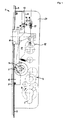
- Fig. 1 shows a schematic representation of an unlocked multi-bolt lock according to the invention during a change operation with retracted latch and retracted latch and with a holding device
- Fig. 2 a shoulder of a push rod of a holding device of a multi-bolt lock with a lever in the unlocked state of the multi-bolt lock after Fig. 1 and Fig. 3 to 5 the displacement of the shoulder during the locking of the multi-bolt lock after Fig. 1 ,
- a multi-bolt lock 1 after Fig. 1 The transmission gear 5 has on a flat side diametrically to the axis of rotation two axially projecting pins 6, which engage in a rack toothing 7 of a push rod slide 8 on a flat side.
- the elongated push rod slide 8 has form-locking connections at its two ends for receiving push rods 9.
- Fig. 1 shows the multi-bolt lock 1 during a change operation, wherein the latch 3 and a case 10 are retracted into the multi-bolt lock 1.
- the push rods 9 push or pull now with its own weight on the push rod slide 8, which rests on the pins 6, in the direction A.
- the multi-bolt lock 1 is now particularly susceptible to shocks, since such shocks can lead to a rotation of the transmission gear 5. Thereafter, the push rod slide 8 would fall in the direction A and get out of sync with the transmission 4.
- the push rod slide 8 has a shoulder 13, which is supported on a lever 14 in a recessed holding portion 15 of a control surface 16. In this way, the transmission gear 5 is relieved of the weight of the push rods 9 and prevents an out-synchronization devices of the transmission gear 5 to the transmission 4.
- the lock cylinder 2 is rotated with the locking lug 3 against the Aufsperrides B.
- the transmission gear 5 engages again, as is known, in the transmission 4 a.
- the transmission gear 5 is rotated in direction A.
- the latch 3 and actuated by means of the push rods 9, not shown auxiliary bolt go out.
- Fig. 2 to 5 show the locking of the multi-bolt lock 1 in detail with reference to the shoulder 13 and the lever 14 in chronological order.
- Fig. 2 corresponds to an enlargement of the already at Fig. 1 described situation, which, as already mentioned, the shoulder 13 is supported with a front edge 18 in the recessed holding portion 15 of the control surface 16 of the lever 14.
- the angled trained lever 14 is rotatably mounted on a circular cylindrical pin 19 and is pressed with a tension spring 17 to the front edge 18 of the shoulder 13.
- the bolt 19 and the fixed tension spring end 23 are fastened to a lock housing 20 of the multi-bolt lock 1.
- the side surface 21 and the control surface 16 have smooth surfaces to reduce the frictional forces during the obstruction of the Multi-latch lock 1 to keep as small as possible.
- the control surface 16 and the sliding portion 22 and the side surface 21 are designed as large as possible.
- the multi-bolt lock 1 is locked - if as in Fig. 5 shown - the sliding portion 22 on the side surface 21 approximately abuts.
- the length of the control surface 16 is composed of the holding portion 15 and the sliding portion 22 and corresponds at least to the stroke of the multi-bolt lock. 1
- a roller may be installed in the sliding portion 22 or in the side surface 21.
- the consisting essentially of shoulder 13, lever 14 and tension spring 17 holding device is preferably disposed within the lock housing 20 of the multi-bolt lock 1. Likewise the holding device may be arranged in the housing of the additional locking mechanism or directly to the push rods 9.
Description
Die Erfindung betrifft eine Mehrriegelschloss mit mindestens einer Schubstange und eine Haltevorrichtung für die Schubstange des Mehrriegelschlosses zur Verhinderung einer insbesondere erschütterungsbedingten Verschiebung relativ zu Eingriffselementen einer Schlossmechanik.The invention relates to a multi-bolt lock with at least one push rod and a holding device for the push rod of the multi-bolt lock to prevent a particular vibration-related displacement relative to engagement elements of a lock mechanism.
Um ein Mehrriegelschloss zu sperren, werden Zusatzriegel mittels Schubstangen in eine Sperrstellung ausgeschoben bzw. aus der Sperrstellung zurückgezogen. Im nicht versperrten Zustand ist das Mehrriegelschloss besonders durch Erschütterungen und Stöße gefährdet, da die Schubstangen leicht außer Synchronisation mit einem Zahnradgetriebe geraten können.To lock a multi-bolt lock, additional bolts are pushed by means of push rods in a blocking position or withdrawn from the locked position. In the unlocked state, the multi-bolt lock is particularly vulnerable to shock and shock, as the push rods can easily get out of sync with a gear transmission.
Ein weiterer Nachteil von Mehrriegelschlössern wird bei einer Ausführung als Panikschloss bemerkbar. In diesem Fall verfügt das Schloss an einer Türblattseite über einen Knauf und auf der zweiten über einen Drücker, wobei das versperrte Schloss in einer so genannten Paniksituation durch eine Drückerbetätigung aufgesperrt werden kann. Weiters ist ein Freilaufzylinder vorgesehen, der von einem Schlossgetriebe während der Drückerbetätigung verdreht wird. Der Zylinder wird also nicht mit einem Schlüssel, sondern von dem Drücker über ein Getriebe betätigt bzw. mitgenommen. Im nicht versperrtem Zustand des Mehrriegelschlosses kann es daher vorkommen, dass die Zusatzriegel durch Erschütterungen sowie das Eigengewicht der Schubstangen ungewollt aus dem Schloss ausfahren, da sich der Freilaufzylinder auch in dieser Situation, ohne Schlüsselbetätigung, verdrehen lässt.Another disadvantage of multi-bolt locks is noticeable in a version as a panic lock. In this case, the lock on one side of the door leaf has a knob and on the second via a pusher, the locked lock can be unlocked in a so-called panic situation by a handle operation. Furthermore, a freewheeling cylinder is provided, which is rotated by a lock gear during the handle operation. The cylinder is thus not actuated by a key, but by the pusher via a gear or taken. In the unlocked state of the multi-bolt lock, it may therefore happen that the additional bolt unintentionally extend from the lock due to shocks and the weight of the push rods, as the freewheel cylinder can be rotated in this situation, without key operation.
Bekannte Haltevorrichtungen für Schubstangen in Fenstern und Türen umfassen beispielsweise einen elastischen Kunststoffteil, der Relativbewegungen zwischen Schubstangen und Stock dämpfend entgegenwirkt. Nachteilig bei diesen Konstruktionen ist jedoch, dass die erzielten Haltekräfte zu gering sind und die Schubstangen immer noch außer Synchronisation geraten können.
Bei der
In the
Die Erfindung zielt darauf ab, das Mehrriegelschloss mit einer alternativen Haltevorrichtung zu versehen.The invention aims to provide the multi-bolt lock with an alternative holding device.
Diese Aufgabe wird durch ein Mehrriegelschloss mit den Merkmalen des Anspruchs 1 gelöst. Der Schubstange und/oder dem Schubstangenschieber ist ein federbelasteter Hebel zugeordnet, der eine Steuerfläche mit einem insbesondere vertieften Haltebereich zur reibungsschlüssigen Anlage an einer Stirnkante einer Schulter, vorzugsweise an der Schubstange, aufweist und dass an den Haltebereich ein ebener Gleitbereich anschließt. Ist das Mehrriegelschloss nicht versperrt, stützt sich die an der Schubstange befestigte Schulter im vertieften Haltebereich in der Steuerfläche des Hebels oder Schiebers ab. Die Schubstange ist somit in ihrer Position fixiert und gegen ein Außer-Synchronisation-Rutschen abgesichert.This object is achieved by a multi-bolt lock with the features of
Die fixierte Schubstange stellt sicher, dass das Eigengewicht der Schubstange bei unversperrtem Schloss nicht auf die Mechanik des Schlosses wirkt und Zahnräder ungewollt verstellt werden. Das ungewollte Verstellen der Zahnräder wird bei herkömmlichen Mehrriegelschlössem insbesondere bei einem Zylinderwechsel bemerkbar, da bei entnommenem Zylinder die Zylindernocke durch das Eigengewicht der Schubstange in den Zylinderkanal bewegt wird.The fixed push rod ensures that the dead weight of the push rod does not affect the mechanics of the lock when unlocked lock and gears are unintentionally adjusted. The unwanted adjustment of the gears is noticeable in conventional Mehrriegelschlössem especially at a cylinder change, as with the cylinder removed the cylinder cam is moved by the weight of the push rod in the cylinder channel.
Die Länge des Gleitbereichs entspricht etwa dem Hub der Schubstange. Auf diese Weise wird sichergestellt, dass der Hebel während des gesamten Sperrzyklus an der Schulter der Schubstange anliegt und sich die Spannfeder, die auf den Hebel wirkt, nicht entspannen kann.The length of the sliding area corresponds approximately to the stroke of the push rod. In this way it is ensured that the lever rests against the shoulder of the push rod during the entire locking cycle and that the tension spring acting on the lever can not relax.
Um ein leichtgängiges Sperren zu gewährleisten, ist vorgesehen, dass der Gleitbereich des Hebels als ebene Fläche an der Schulter reibungsarm anliegt.To ensure a smooth locking, it is provided that the sliding portion of the lever abuts a flat surface on the shoulder friction.
Um die Reibungskräfte zwischen dem Hebel und der Stirnkante der Schulter weiter zu vermindern, ist vorgesehen, dass der Hebel oder die Schulter über eine Walze zum gegenseitigen reibungsarmen Ablaufen verfügt.In order to further reduce the frictional forces between the lever and the front edge of the shoulder, it is provided that the lever or the shoulder has a roller for mutual low-friction running.
Schließlich ist es zweckmäßig, wenn die Haltevorrichtung in einem Schlossgehäuse und/oder in einem Gehäuse für den Zusatzriegelantrieb angeordnet ist. Dadurch wird einerseits die Montage vereinfacht und anderseits die Haltevorrichtung vor Verschmutzungen oder Beschädigungen geschützt.Finally, it is expedient if the holding device is arranged in a lock housing and / or in a housing for the additional bolt drive. As a result, on the one hand, the assembly is simplified and on the other hand, the holding device protected from dirt or damage.
Ein Ausführungsbeispiel des Erfindungsgegenstandes ist in den beiliegenden Zeichnungen dargestellt.An embodiment of the subject invention is illustrated in the accompanying drawings.
Ein Mehrriegelschloss 1 nach
Die Betätigung des Wechsels erfolgt mittels eines Wechselhebels 11 und eines Winkelhebels 12, wenn bei eingezogenem Riegel 3 der Schließzylinder 2 weiter in einer Aufsperrrichtung B betätigt wird. Ein weiteres Einziehen des Riegels 3 wird, wie bekannt, durch Auskuppeln des Getriebezahnrades 5 aus dem Getriebe 4 unterbunden.The operation of the change takes place by means of an exchange lever 11 and an
Die Schubstangen 9 drücken bzw. ziehen nun mit ihrem Eigengewicht an dem Schubstangenschieber 8, der auf den Stiften 6 ruht, in der Richtung A.The push rods 9 push or pull now with its own weight on the
Das Mehrriegelschloss 1 ist nun besonders anfällig für Stöße, da solche Erschütterungen zu einer Verdrehung des Getriebezahnrades 5 führen können. Danach würde der Schubstangenschieber 8 in Richtung A absinken und mit dem Getriebe 4 außer Synchronisation geraten.The
Um dies zu verhindern, verfügt der Schubstangenschieber 8 über eine Schulter 13, die sich auf einem Hebel 14 in einem vertieften Haltebereich 15 einer Steuerfläche 16 abstützt. Auf diese Weise wird das Getriebezahnrad 5 von dem Gewicht der Schubstangen 9 entlastet und ein Außer-Synchronisation-Geraten des Getriebezahnrades 5 mit dem Getriebe 4 verhindert.To prevent this, the
Um das Mehrriegelschloss 1 zu versperren, wird der Schließzylinder 2 mit der Sperrnase 3 gegen die Aufsperrrichtung B verdreht. Das Getriebezahnrad 5 kuppelt wieder, wie bekannt, in das Getriebe 4 ein. Bei der Betätigung wird das Getriebezahnrad 5 in Richtung A verdreht. Durch das Eingreifen der Stifte 6 in die Zahnstangenverzahnung 7 wird der Schubstangenschieber 8 ebenfalls gemeinsam mit den Schubstangen 9 in Richtung A verschoben. Der Riegel 3 und die mittels der Schubstangen 9 betätigten, nicht dargestellten Hilfsriegel fahren aus.To block the
Der gewinkelt ausgebildete Hebel 14 ist an einem kreiszylinderförmigen Bolzen 19 drehbar gelagert und wird mit einer Spannfeder 17 an die Stirnkante 18 der Schulter 13 angedrückt. Der Bolzen 19 und das fixierte Spannfederende 23 sind an einem Schlossgehäuse 20 des Mehrriegelschlosses 1 befestigt.The angled trained
Durch weiteres Verdrehen des Schließzylinders 2 gegen die Aufsperrrichtung B wird die Schubstange 8 gemeinsam mit der Schulter 13 in Richtung A verschoben. Gemäß
Die Seitenfläche 21 und die Steuerfläche 16 verfügen über glatte Oberflächen, um die Reibungskräfte während des Versperrens des Mehrriegelschlosses 1 möglichst klein zu halten. Um den Verschleiß auch durch oftmalige Betätigung des Mehrriegelschlosses 1 gering zu halten, sind die Steuerfläche 16 bzw. der Gleitbereich 22 und die Seitenfläche 21 möglichst großflächig ausgeführt. Das Mehrriegelschloss 1 ist versperrt - wenn wie in
Wird der Schließzylinder 2 im Uhrzeigersinn wieder in der Aufsperrrichtung B betätigt, wird der Schubstangenschieber 8 mit der Schulter 13 wieder zurück, also entgegen der Richtung A, verschoben. Wenn die Stirnkante 18 den Haltebereich 15 des Hebels 14 wieder erreicht hat, schwenkt der Hebel 14 durch die Kraft der Spannfeder 17 wieder unter die Schulter 13 zurück, wie in
Um die Reibungskräfte während des Aneinandergleitens der Seitenfläche 21 der Schulter 13 und des Gleitbereiches 22 des Hebels 14 möglichst gering zu halten, kann in den Gleitbereich 22 oder in die Seitenfläche 21 eine Walze eingebaut werden.In order to minimize the frictional forces during the sliding of the
Die im Wesentlichen aus Schulter 13, Hebel 14 und Spannfeder 17 bestehende Haltevorrichtung ist vorzugsweise innerhalb des Schlossgehäuses 20 des Mehrriegelschlosses 1 angeordnet. Ebenso kann die Haltevorrichtung im Gehäuse der Zusatzriegelmechanik oder direkt an den Schubstangen 9 angeordnet sein.The consisting essentially of
Claims (3)
- A multi-bolt lock having at least one push rod and having a holding device for preventing a displacement caused in particular by vibration in relation to engaging elements of a lock mechanism, characterised in that associated with the push rod (9) and/or the push-rod slide (8) there is a spring-loaded lever (14) that has a control face (16) with a holding region (15), which in particular is recessed, for friction-locking abutment on a front edge (18) of a shoulder (13), preferably on the push rod (9), and in that following on from the holding region (15) there is a sliding region (22) that is formed as a planar smooth surface and the length of which substantially corresponds to the stroke of the push rod (9) and which is provided for low-friction, large-area abutment on a smooth side face (21) of the shoulder (13).
- A multi-bolt lock according to claim 1, characterised in that the lever (14) or the shoulder (13) is provided with a roller for mutual low-friction run-off.
- A multi-bolt lock according to one of claims 1 or 2, characterised in that the holding device is arranged in a lock housing (20) and/or in a housing for the additional bolt drive.
Priority Applications (1)
| Application Number | Priority Date | Filing Date | Title |
|---|---|---|---|
| SI200431551T SI1455041T1 (en) | 2003-03-06 | 2004-03-05 | Lock with drive bar and dogging device. |
Applications Claiming Priority (2)
| Application Number | Priority Date | Filing Date | Title |
|---|---|---|---|
| AT3382003 | 2003-03-06 | ||
| AT0033803A AT413044B (en) | 2003-03-06 | 2003-03-06 | HOLDING DEVICE FOR A DRAWER OR DRAWER PUSHER OF A MULTIPLE LOCK |
Publications (3)
| Publication Number | Publication Date |
|---|---|
| EP1455041A2 EP1455041A2 (en) | 2004-09-08 |
| EP1455041A3 EP1455041A3 (en) | 2007-11-14 |
| EP1455041B1 true EP1455041B1 (en) | 2010-09-01 |
Family
ID=32777529
Family Applications (1)
| Application Number | Title | Priority Date | Filing Date |
|---|---|---|---|
| EP04100897A Expired - Fee Related EP1455041B1 (en) | 2003-03-06 | 2004-03-05 | Lock with drive bar and dogging device. |
Country Status (4)
| Country | Link |
|---|---|
| EP (1) | EP1455041B1 (en) |
| AT (2) | AT413044B (en) |
| DE (1) | DE502004011598D1 (en) |
| SI (1) | SI1455041T1 (en) |
Families Citing this family (2)
| Publication number | Priority date | Publication date | Assignee | Title |
|---|---|---|---|---|
| ITMI20091722A1 (en) * | 2009-10-08 | 2011-04-09 | Iseo Serrature Spa | MULTI-POINT BOLT LOCK |
| DE102016221101A1 (en) | 2016-10-26 | 2018-04-26 | Aug. Winkhaus Gmbh & Co. Kg | lock |
Family Cites Families (4)
| Publication number | Priority date | Publication date | Assignee | Title |
|---|---|---|---|---|
| DE3605826A1 (en) * | 1986-02-22 | 1987-08-27 | Fliether Karl Gmbh & Co | Espagnolette fastening with handle return |
| FR2687185B1 (en) * | 1992-02-12 | 1994-04-08 | Vachette | DOOR LOCK PROVIDING A SEALING AND SECURITY FUNCTION. |
| DE29920508U1 (en) * | 1999-11-23 | 2000-02-24 | Gretsch Unitas Gmbh | Espagnolette lock |
| FR2809446A1 (en) * | 2000-05-29 | 2001-11-30 | Usine Metallurg Altkirch | Lock for building window has housing formed from stamped and folded metal sheet with integral guide ribs for gear wheel shaft and rack |
-
2003
- 2003-03-06 AT AT0033803A patent/AT413044B/en not_active IP Right Cessation
-
2004
- 2004-03-05 SI SI200431551T patent/SI1455041T1/en unknown
- 2004-03-05 DE DE502004011598T patent/DE502004011598D1/en not_active Expired - Lifetime
- 2004-03-05 AT AT04100897T patent/ATE479808T1/en active
- 2004-03-05 EP EP04100897A patent/EP1455041B1/en not_active Expired - Fee Related
Also Published As
| Publication number | Publication date |
|---|---|
| EP1455041A3 (en) | 2007-11-14 |
| DE502004011598D1 (en) | 2010-10-14 |
| AT413044B (en) | 2005-10-15 |
| ATE479808T1 (en) | 2010-09-15 |
| ATA3382003A (en) | 2005-03-15 |
| EP1455041A2 (en) | 2004-09-08 |
| SI1455041T1 (en) | 2011-01-31 |
Similar Documents
| Publication | Publication Date | Title |
|---|---|---|
| EP0915221B1 (en) | Lock, in particular mortise lock for an entrance door | |
| DE3447748C2 (en) | ||
| EP1932989B1 (en) | Locking device for doors, windows or similar, in particular an espagnolette lock with panic function and multi-point locking | |
| EP0359284B1 (en) | Espagnolet | |
| DE102007035116A1 (en) | Jointed bar lock | |
| EP1049845B1 (en) | Lock with a latch bolt protruding from the lock housing | |
| EP0413177A1 (en) | Lock for driving rod | |
| EP1900891A2 (en) | Flap closure lever | |
| DE4014041A1 (en) | LOCKING CYLINDER ACTUATED ROD LOCK | |
| EP3805493B1 (en) | Modular lock with panic function | |
| DE102015000606A1 (en) | Locking device for a pivotally mounted wing | |
| DE4114007A1 (en) | Main rod lock operated by pushbutton - incorporates stop component preventing drive unit moving from closed to open positions | |
| EP1455041B1 (en) | Lock with drive bar and dogging device. | |
| DE19653611B4 (en) | Lock with latch and latch | |
| DE202007016091U1 (en) | Espagnolette | |
| DE19815671B4 (en) | Bolt lock | |
| DE3840183C2 (en) | Hardware for windows or doors | |
| EP2792828A2 (en) | Retaining device for sliding doors and locking device for sliding doors | |
| EP0454959A2 (en) | Plug actuated sliding bar lock | |
| DE3342458C2 (en) | ||
| DE102016112554A1 (en) | Arrangement with a frame for the storage of a sash | |
| AT390989B (en) | DOOR LOCK WITH SLIDING LATCH AND LATCH | |
| DE4014042A1 (en) | DRIVE ROD LOCK | |
| WO2009039899A1 (en) | Electronic lock | |
| DE3427713A1 (en) | Espagnolette lock with multi-turn closing |
Legal Events
| Date | Code | Title | Description |
|---|---|---|---|
| PUAI | Public reference made under article 153(3) epc to a published international application that has entered the european phase |
Free format text: ORIGINAL CODE: 0009012 |
|
| AK | Designated contracting states |
Kind code of ref document: A2 Designated state(s): AT BE BG CH CY CZ DE DK EE ES FI FR GB GR HU IE IT LI LU MC NL PL PT RO SE SI SK TR |
|
| AX | Request for extension of the european patent |
Extension state: AL LT LV MK |
|
| PUAL | Search report despatched |
Free format text: ORIGINAL CODE: 0009013 |
|
| AK | Designated contracting states |
Kind code of ref document: A3 Designated state(s): AT BE BG CH CY CZ DE DK EE ES FI FR GB GR HU IE IT LI LU MC NL PL PT RO SE SI SK TR |
|
| AX | Request for extension of the european patent |
Extension state: AL LT LV MK |
|
| 17P | Request for examination filed |
Effective date: 20080103 |
|
| AKX | Designation fees paid |
Designated state(s): AT DE FR GB IT SI |
|
| RTI1 | Title (correction) |
Free format text: LOCK WITH DRIVE BAR AND DOGGING DEVICE. |
|
| GRAP | Despatch of communication of intention to grant a patent |
Free format text: ORIGINAL CODE: EPIDOSNIGR1 |
|
| GRAS | Grant fee paid |
Free format text: ORIGINAL CODE: EPIDOSNIGR3 |
|
| GRAA | (expected) grant |
Free format text: ORIGINAL CODE: 0009210 |
|
| AK | Designated contracting states |
Kind code of ref document: B1 Designated state(s): AT DE FR GB IT SI |
|
| REG | Reference to a national code |
Ref country code: GB Ref legal event code: FG4D Free format text: NOT ENGLISH |
|
| REF | Corresponds to: |
Ref document number: 502004011598 Country of ref document: DE Date of ref document: 20101014 Kind code of ref document: P |
|
| RAP2 | Party data changed (patent owner data changed or rights of a patent transferred) |
Owner name: ROTO FRANK AG |
|
| PLBE | No opposition filed within time limit |
Free format text: ORIGINAL CODE: 0009261 |
|
| STAA | Information on the status of an ep patent application or granted ep patent |
Free format text: STATUS: NO OPPOSITION FILED WITHIN TIME LIMIT |
|
| 26N | No opposition filed |
Effective date: 20110606 |
|
| REG | Reference to a national code |
Ref country code: DE Ref legal event code: R097 Ref document number: 502004011598 Country of ref document: DE Effective date: 20110606 |
|
| PGFP | Annual fee paid to national office [announced via postgrant information from national office to epo] |
Ref country code: SI Payment date: 20120227 Year of fee payment: 9 |
|
| PGFP | Annual fee paid to national office [announced via postgrant information from national office to epo] |
Ref country code: IT Payment date: 20120328 Year of fee payment: 9 Ref country code: GB Payment date: 20120321 Year of fee payment: 9 |
|
| PGFP | Annual fee paid to national office [announced via postgrant information from national office to epo] |
Ref country code: FR Payment date: 20120416 Year of fee payment: 9 |
|
| PGFP | Annual fee paid to national office [announced via postgrant information from national office to epo] |
Ref country code: AT Payment date: 20120402 Year of fee payment: 9 |
|
| PG25 | Lapsed in a contracting state [announced via postgrant information from national office to epo] |
Ref country code: SI Free format text: LAPSE BECAUSE OF NON-PAYMENT OF DUE FEES Effective date: 20130306 |
|
| REG | Reference to a national code |
Ref country code: AT Ref legal event code: MM01 Ref document number: 479808 Country of ref document: AT Kind code of ref document: T Effective date: 20130305 |
|
| GBPC | Gb: european patent ceased through non-payment of renewal fee |
Effective date: 20130305 |
|
| REG | Reference to a national code |
Ref country code: SI Ref legal event code: KO00 Effective date: 20131009 |
|
| REG | Reference to a national code |
Ref country code: FR Ref legal event code: ST Effective date: 20131129 |
|
| PG25 | Lapsed in a contracting state [announced via postgrant information from national office to epo] |
Ref country code: FR Free format text: LAPSE BECAUSE OF NON-PAYMENT OF DUE FEES Effective date: 20130402 Ref country code: AT Free format text: LAPSE BECAUSE OF NON-PAYMENT OF DUE FEES Effective date: 20130305 Ref country code: GB Free format text: LAPSE BECAUSE OF NON-PAYMENT OF DUE FEES Effective date: 20130305 |
|
| PG25 | Lapsed in a contracting state [announced via postgrant information from national office to epo] |
Ref country code: IT Free format text: LAPSE BECAUSE OF NON-PAYMENT OF DUE FEES Effective date: 20130305 |
|
| PGFP | Annual fee paid to national office [announced via postgrant information from national office to epo] |
Ref country code: DE Payment date: 20200226 Year of fee payment: 17 |
|
| REG | Reference to a national code |
Ref country code: DE Ref legal event code: R119 Ref document number: 502004011598 Country of ref document: DE |
|
| PG25 | Lapsed in a contracting state [announced via postgrant information from national office to epo] |
Ref country code: DE Free format text: LAPSE BECAUSE OF NON-PAYMENT OF DUE FEES Effective date: 20211001 |