EP3802245B1 - Method for controlling a braking system of a vehicle and related system - Google Patents
Method for controlling a braking system of a vehicle and related system Download PDFInfo
- Publication number
- EP3802245B1 EP3802245B1 EP19731349.7A EP19731349A EP3802245B1 EP 3802245 B1 EP3802245 B1 EP 3802245B1 EP 19731349 A EP19731349 A EP 19731349A EP 3802245 B1 EP3802245 B1 EP 3802245B1
- Authority
- EP
- European Patent Office
- Prior art keywords
- vehicle
- information
- data processing
- processing block
- condition
- Prior art date
- Legal status (The legal status is an assumption and is not a legal conclusion. Google has not performed a legal analysis and makes no representation as to the accuracy of the status listed.)
- Active
Links
Images


Classifications
-
- B—PERFORMING OPERATIONS; TRANSPORTING
- B60—VEHICLES IN GENERAL
- B60T—VEHICLE BRAKE CONTROL SYSTEMS OR PARTS THEREOF; BRAKE CONTROL SYSTEMS OR PARTS THEREOF, IN GENERAL; ARRANGEMENT OF BRAKING ELEMENTS ON VEHICLES IN GENERAL; PORTABLE DEVICES FOR PREVENTING UNWANTED MOVEMENT OF VEHICLES; VEHICLE MODIFICATIONS TO FACILITATE COOLING OF BRAKES
- B60T8/00—Arrangements for adjusting wheel-braking force to meet varying vehicular or ground-surface conditions, e.g. limiting or varying distribution of braking force
- B60T8/17—Using electrical or electronic regulation means to control braking
- B60T8/171—Detecting parameters used in the regulation; Measuring values used in the regulation
-
- B—PERFORMING OPERATIONS; TRANSPORTING
- B60—VEHICLES IN GENERAL
- B60T—VEHICLE BRAKE CONTROL SYSTEMS OR PARTS THEREOF; BRAKE CONTROL SYSTEMS OR PARTS THEREOF, IN GENERAL; ARRANGEMENT OF BRAKING ELEMENTS ON VEHICLES IN GENERAL; PORTABLE DEVICES FOR PREVENTING UNWANTED MOVEMENT OF VEHICLES; VEHICLE MODIFICATIONS TO FACILITATE COOLING OF BRAKES
- B60T13/00—Transmitting braking action from initiating means to ultimate brake actuator with power assistance or drive; Brake systems incorporating such transmitting means, e.g. air-pressure brake systems
- B60T13/74—Transmitting braking action from initiating means to ultimate brake actuator with power assistance or drive; Brake systems incorporating such transmitting means, e.g. air-pressure brake systems with electrical assistance or drive
-
- B—PERFORMING OPERATIONS; TRANSPORTING
- B60—VEHICLES IN GENERAL
- B60T—VEHICLE BRAKE CONTROL SYSTEMS OR PARTS THEREOF; BRAKE CONTROL SYSTEMS OR PARTS THEREOF, IN GENERAL; ARRANGEMENT OF BRAKING ELEMENTS ON VEHICLES IN GENERAL; PORTABLE DEVICES FOR PREVENTING UNWANTED MOVEMENT OF VEHICLES; VEHICLE MODIFICATIONS TO FACILITATE COOLING OF BRAKES
- B60T7/00—Brake-action initiating means
- B60T7/12—Brake-action initiating means for automatic initiation; for initiation not subject to will of driver or passenger
-
- B—PERFORMING OPERATIONS; TRANSPORTING
- B60—VEHICLES IN GENERAL
- B60T—VEHICLE BRAKE CONTROL SYSTEMS OR PARTS THEREOF; BRAKE CONTROL SYSTEMS OR PARTS THEREOF, IN GENERAL; ARRANGEMENT OF BRAKING ELEMENTS ON VEHICLES IN GENERAL; PORTABLE DEVICES FOR PREVENTING UNWANTED MOVEMENT OF VEHICLES; VEHICLE MODIFICATIONS TO FACILITATE COOLING OF BRAKES
- B60T8/00—Arrangements for adjusting wheel-braking force to meet varying vehicular or ground-surface conditions, e.g. limiting or varying distribution of braking force
- B60T8/17—Using electrical or electronic regulation means to control braking
- B60T8/172—Determining control parameters used in the regulation, e.g. by calculations involving measured or detected parameters
-
- B—PERFORMING OPERATIONS; TRANSPORTING
- B60—VEHICLES IN GENERAL
- B60T—VEHICLE BRAKE CONTROL SYSTEMS OR PARTS THEREOF; BRAKE CONTROL SYSTEMS OR PARTS THEREOF, IN GENERAL; ARRANGEMENT OF BRAKING ELEMENTS ON VEHICLES IN GENERAL; PORTABLE DEVICES FOR PREVENTING UNWANTED MOVEMENT OF VEHICLES; VEHICLE MODIFICATIONS TO FACILITATE COOLING OF BRAKES
- B60T8/00—Arrangements for adjusting wheel-braking force to meet varying vehicular or ground-surface conditions, e.g. limiting or varying distribution of braking force
- B60T8/32—Arrangements for adjusting wheel-braking force to meet varying vehicular or ground-surface conditions, e.g. limiting or varying distribution of braking force responsive to a speed condition, e.g. acceleration or deceleration
- B60T8/88—Arrangements for adjusting wheel-braking force to meet varying vehicular or ground-surface conditions, e.g. limiting or varying distribution of braking force responsive to a speed condition, e.g. acceleration or deceleration with failure responsive means, i.e. means for detecting and indicating faulty operation of the speed responsive control means
- B60T8/885—Arrangements for adjusting wheel-braking force to meet varying vehicular or ground-surface conditions, e.g. limiting or varying distribution of braking force responsive to a speed condition, e.g. acceleration or deceleration with failure responsive means, i.e. means for detecting and indicating faulty operation of the speed responsive control means using electrical circuitry
-
- B—PERFORMING OPERATIONS; TRANSPORTING
- B60—VEHICLES IN GENERAL
- B60T—VEHICLE BRAKE CONTROL SYSTEMS OR PARTS THEREOF; BRAKE CONTROL SYSTEMS OR PARTS THEREOF, IN GENERAL; ARRANGEMENT OF BRAKING ELEMENTS ON VEHICLES IN GENERAL; PORTABLE DEVICES FOR PREVENTING UNWANTED MOVEMENT OF VEHICLES; VEHICLE MODIFICATIONS TO FACILITATE COOLING OF BRAKES
- B60T8/00—Arrangements for adjusting wheel-braking force to meet varying vehicular or ground-surface conditions, e.g. limiting or varying distribution of braking force
- B60T8/32—Arrangements for adjusting wheel-braking force to meet varying vehicular or ground-surface conditions, e.g. limiting or varying distribution of braking force responsive to a speed condition, e.g. acceleration or deceleration
- B60T8/88—Arrangements for adjusting wheel-braking force to meet varying vehicular or ground-surface conditions, e.g. limiting or varying distribution of braking force responsive to a speed condition, e.g. acceleration or deceleration with failure responsive means, i.e. means for detecting and indicating faulty operation of the speed responsive control means
- B60T8/92—Arrangements for adjusting wheel-braking force to meet varying vehicular or ground-surface conditions, e.g. limiting or varying distribution of braking force responsive to a speed condition, e.g. acceleration or deceleration with failure responsive means, i.e. means for detecting and indicating faulty operation of the speed responsive control means automatically taking corrective action
- B60T8/96—Arrangements for adjusting wheel-braking force to meet varying vehicular or ground-surface conditions, e.g. limiting or varying distribution of braking force responsive to a speed condition, e.g. acceleration or deceleration with failure responsive means, i.e. means for detecting and indicating faulty operation of the speed responsive control means automatically taking corrective action on speed responsive control means
-
- B—PERFORMING OPERATIONS; TRANSPORTING
- B60—VEHICLES IN GENERAL
- B60T—VEHICLE BRAKE CONTROL SYSTEMS OR PARTS THEREOF; BRAKE CONTROL SYSTEMS OR PARTS THEREOF, IN GENERAL; ARRANGEMENT OF BRAKING ELEMENTS ON VEHICLES IN GENERAL; PORTABLE DEVICES FOR PREVENTING UNWANTED MOVEMENT OF VEHICLES; VEHICLE MODIFICATIONS TO FACILITATE COOLING OF BRAKES
- B60T2201/00—Particular use of vehicle brake systems; Special systems using also the brakes; Special software modules within the brake system controller
- B60T2201/03—Brake assistants
-
- B—PERFORMING OPERATIONS; TRANSPORTING
- B60—VEHICLES IN GENERAL
- B60T—VEHICLE BRAKE CONTROL SYSTEMS OR PARTS THEREOF; BRAKE CONTROL SYSTEMS OR PARTS THEREOF, IN GENERAL; ARRANGEMENT OF BRAKING ELEMENTS ON VEHICLES IN GENERAL; PORTABLE DEVICES FOR PREVENTING UNWANTED MOVEMENT OF VEHICLES; VEHICLE MODIFICATIONS TO FACILITATE COOLING OF BRAKES
- B60T2201/00—Particular use of vehicle brake systems; Special systems using also the brakes; Special software modules within the brake system controller
- B60T2201/10—Automatic or semi-automatic parking aid systems
-
- B—PERFORMING OPERATIONS; TRANSPORTING
- B60—VEHICLES IN GENERAL
- B60T—VEHICLE BRAKE CONTROL SYSTEMS OR PARTS THEREOF; BRAKE CONTROL SYSTEMS OR PARTS THEREOF, IN GENERAL; ARRANGEMENT OF BRAKING ELEMENTS ON VEHICLES IN GENERAL; PORTABLE DEVICES FOR PREVENTING UNWANTED MOVEMENT OF VEHICLES; VEHICLE MODIFICATIONS TO FACILITATE COOLING OF BRAKES
- B60T2210/00—Detection or estimation of road or environment conditions; Detection or estimation of road shapes
- B60T2210/10—Detection or estimation of road conditions
-
- B—PERFORMING OPERATIONS; TRANSPORTING
- B60—VEHICLES IN GENERAL
- B60T—VEHICLE BRAKE CONTROL SYSTEMS OR PARTS THEREOF; BRAKE CONTROL SYSTEMS OR PARTS THEREOF, IN GENERAL; ARRANGEMENT OF BRAKING ELEMENTS ON VEHICLES IN GENERAL; PORTABLE DEVICES FOR PREVENTING UNWANTED MOVEMENT OF VEHICLES; VEHICLE MODIFICATIONS TO FACILITATE COOLING OF BRAKES
- B60T2210/00—Detection or estimation of road or environment conditions; Detection or estimation of road shapes
- B60T2210/30—Environment conditions or position therewithin
- B60T2210/36—Global Positioning System [GPS]
-
- B—PERFORMING OPERATIONS; TRANSPORTING
- B60—VEHICLES IN GENERAL
- B60T—VEHICLE BRAKE CONTROL SYSTEMS OR PARTS THEREOF; BRAKE CONTROL SYSTEMS OR PARTS THEREOF, IN GENERAL; ARRANGEMENT OF BRAKING ELEMENTS ON VEHICLES IN GENERAL; PORTABLE DEVICES FOR PREVENTING UNWANTED MOVEMENT OF VEHICLES; VEHICLE MODIFICATIONS TO FACILITATE COOLING OF BRAKES
- B60T2220/00—Monitoring, detecting driver behaviour; Signalling thereof; Counteracting thereof
- B60T2220/04—Pedal travel sensor, stroke sensor; Sensing brake request
-
- B—PERFORMING OPERATIONS; TRANSPORTING
- B60—VEHICLES IN GENERAL
- B60T—VEHICLE BRAKE CONTROL SYSTEMS OR PARTS THEREOF; BRAKE CONTROL SYSTEMS OR PARTS THEREOF, IN GENERAL; ARRANGEMENT OF BRAKING ELEMENTS ON VEHICLES IN GENERAL; PORTABLE DEVICES FOR PREVENTING UNWANTED MOVEMENT OF VEHICLES; VEHICLE MODIFICATIONS TO FACILITATE COOLING OF BRAKES
- B60T2220/00—Monitoring, detecting driver behaviour; Signalling thereof; Counteracting thereof
- B60T2220/06—Adjustment of accelerator pedal reaction forces
-
- B—PERFORMING OPERATIONS; TRANSPORTING
- B60—VEHICLES IN GENERAL
- B60T—VEHICLE BRAKE CONTROL SYSTEMS OR PARTS THEREOF; BRAKE CONTROL SYSTEMS OR PARTS THEREOF, IN GENERAL; ARRANGEMENT OF BRAKING ELEMENTS ON VEHICLES IN GENERAL; PORTABLE DEVICES FOR PREVENTING UNWANTED MOVEMENT OF VEHICLES; VEHICLE MODIFICATIONS TO FACILITATE COOLING OF BRAKES
- B60T2240/00—Monitoring, detecting wheel/tyre behaviour; counteracting thereof
-
- B—PERFORMING OPERATIONS; TRANSPORTING
- B60—VEHICLES IN GENERAL
- B60T—VEHICLE BRAKE CONTROL SYSTEMS OR PARTS THEREOF; BRAKE CONTROL SYSTEMS OR PARTS THEREOF, IN GENERAL; ARRANGEMENT OF BRAKING ELEMENTS ON VEHICLES IN GENERAL; PORTABLE DEVICES FOR PREVENTING UNWANTED MOVEMENT OF VEHICLES; VEHICLE MODIFICATIONS TO FACILITATE COOLING OF BRAKES
- B60T2250/00—Monitoring, detecting, estimating vehicle conditions
-
- B—PERFORMING OPERATIONS; TRANSPORTING
- B60—VEHICLES IN GENERAL
- B60T—VEHICLE BRAKE CONTROL SYSTEMS OR PARTS THEREOF; BRAKE CONTROL SYSTEMS OR PARTS THEREOF, IN GENERAL; ARRANGEMENT OF BRAKING ELEMENTS ON VEHICLES IN GENERAL; PORTABLE DEVICES FOR PREVENTING UNWANTED MOVEMENT OF VEHICLES; VEHICLE MODIFICATIONS TO FACILITATE COOLING OF BRAKES
- B60T2270/00—Further aspects of brake control systems not otherwise provided for
- B60T2270/88—Pressure measurement in brake systems
Definitions
- the present invention relates to a braking system of a vehicle, in particular to a method for controlling a braking system of a vehicle and a related system.
- Cars and road vehicles with more than two wheels intended to transport passengers in general are equipped with a handbrake, the function of which is to lock the wheels of the vehicle thus preventing its movement when it is parked.
- the EPB electric park brake is to all effects a sub-system of a BBW electronic braking system which is used to for service braking.
- the driver can activate the wheel locking mechanism by means of a button which, once pressed, sends a braking park activation request to an electronic control unit of the vehicle which electrically actuates the brake pads to lock the brake discs and thus the movement of the vehicle.
- the EPB sub-system is configured to provide automatic supporting functions to the driver, such as the so-called "AUTO-HOLD" function, i.e. for locking the wheels automatically and without the driver's request when the vehicle is stationary, e.g. uphill, and releasing them as soon as the driver presses the accelerator pedal of the vehicle.
- AUTO-HOLD automatic supporting functions
- the EPB sub-system can perform a park braking but also greater safety, ease and assistance to the driver in the use of the vehicle when the vehicle is stationary or stops during a journey.
- the vehicle control unit processes information representative of the rotation speed of all wheels of the vehicle provided by respective speed sensors of the encoder type associated with the individual wheels.
- WO 2016/024907 A1 relates to a method for preventing undesired movements of a motor vehicle combination comprising a tractor vehicle and a towed vehicle.
- EP 3315369 A1 discloses an apparatus for controlling a traction of a vehicle.
- WO 2011/096938 A1 describes a multi-wheeled vehicle having an electric parking brake responsive to a control signal to selectably apply braking following parking of the vehicle.
- the present invention also relates to an electronic control system of a braking system of a vehicle according to claim 13.
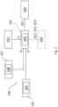
- reference numeral 100 indicates as a whole an electronic control system of a braking system of a vehicle, hereinafter also electronic system or simply system, according to the present invention.
- vehicle means any vehicle or motorcycle, also of commercial type, having two, three, four or more wheels.
- braking system means a set of all components (mechanical and/or electric or electronic, also the brake fluid) which contribute to generating the braking of a vehicle, whether it be a service braking or a parking braking.
- the system 100 in an embodiment comprises a first plurality 101 of detection devices distributed on the braking system of the vehicle configured to detect first information I1 representative of a condition of motion of the vehicle.
- each device of said first plurality 101 of detection devices belongs to the group consisting of: rotation speed sensor of a vehicle wheel; position sensor of a brake pedal of the vehicle; position sensor of an accelerator pedal of the vehicle; force or pressure sensors connected to the brake pedal and/or accelerator pedal or connected to brake calipers or respective actuators of the brake calipers of the braking system or other components of the braking system.
- first information I1 representative of a condition of motion of the vehicle means the information or a combination of the information detected by each of the detection devices of said first plurality 101 of detection devices distributed in the braking system of the vehicle.
- each piece of information I1 depends on the type of detection device.
- the first information I1 will be the vehicle speed estimated from the rotation speed (wheel revolutions) of the vehicle wheel. Such an estimate can be obtained, for example, by averaging the speed of one wheel of the vehicle with respect to the other wheels or by taking the median rotation speed of all the wheels of the vehicle or other combination.
- the first information I1 may be a braking request of the vehicle or an acceleration request of the vehicle.
- the vehicle braking request or the vehicle acceleration request may be determined, respectively, on the basis of the position of the brake pedal of the vehicle or of the accelerator pedal of the vehicle, and a respective characteristic curve (e.g. the position of the brake pedal of the vehicle/braking request or the position of the accelerator pedal of the vehicle/acceleration request).
- condition of motion is related to whether the vehicle is traveling (e.g. vehicle speed not zero, no braking request and acceleration request not zero) or not (e.g. zero vehicle speed, non-zero braking request and any acceleration request). It should be noted that the examples shown define typical cases and are those which increase the reliability of the information representative of the condition of motion of the vehicle, but may not always be true.
- the system 100 in an embodiment, comprises a first driver assistance sub-system 102 associated with the vehicle, hereinafter also simply first sub-system 102.
- the first sub-system 102 is the set of mechanical and/or electrical and/or electronic components which contribute to providing advanced service to the driver while driving.
- One type of such a first sub-system 102 is also known by the acronym ADAS, (Advanced Driver Assistance System).
- the first sub-system 102 comprises a second plurality 103 of detection devices configured to detect second information I2 representative of a condition of motion of the vehicle.
- the second plurality 103 of detection devices comprises any device installed aboard the vehicle and belonging to the first sub-system 102, i.e. a sub-system of ADAS type, adapted and configured to provide information on the position of the vehicle by means of which it is possible to estimate the condition of motion of the vehicle, i.e. whether the vehicle is moving or not.
- Such detection devices of the aforesaid type may be either passive or active.
- a passive detection device is such as to receive information passively.
- Examples of passive type detection devices present in the first sub-system 102 of ADAS type are: a digital camera, an infrared digital camera, a satellite navigation system, e.g. of GPS (Global Positioning System) type or equivalent.
- GPS Global Positioning System
- An active detection device is configured to emit radiation and measure the response of the irradiated signals reflected by objects. This type of detection device advantageously allows measurements to be taken regardless of lighting conditions in the environment surrounding the vehicle, i.e. of the season or hour of the day.
- Examples of active type detection devices present in the first sub-system 102, of the ADAS type, are: long range type radar module, a short/medium range type radar module, LIDAR type remote sensing module or ultrasound detection module.
- each device of said second plurality 103 of detection devices belongs to the group consisting of: digital camera; infrared digital camera; satellite navigation system, GPS or the like; long range radar module; short/medium range radar module; remote sensing module of LIDAR type; ultrasound detection module.
- second information I2 representative of a condition of motion of the vehicle means the information or a combination of the information detected by each of the detection devices of the aforesaid second plurality 103 belonging to the first driver assistance sub-system 102 associated with the vehicle.
- each piece of information I2 depends on the type of detection device.
- the second information I2 may be a digital image from which to estimate the speed and/or "stopped" position of the vehicle. For example, this may be estimated by detecting the same digital image without any change for a respective set interval of time.
- the second information I2 may be an estimate of the vehicle speed and/or an estimate of the "stopped" position of the vehicle. For example, this can be estimated by detecting the same position without any variation or the same zero speed for a respective set interval of time.
- the second information I2 may be an estimate of the vehicle speed according to the speed of another vehicle.
- the second information I2 may be an estimate of the vehicle speed starting from the interpolation of a plurality of points in space. For example, this may be estimated by measuring the same information for a respective predetermined interval of time.
- condition of motion is related to whether the vehicle is traveling (vehicle speed not zero) or not (vehicle speed zero).
- the system 100 further comprises a vehicle braking module 104.
- the braking module 104 is part of the braking system of the vehicle.
- the braking module 104 is configured to apply a braking action on one or more motion components of the vehicle (e.g. the vehicle wheels, not shown in the figures) operatively connected to the vehicle braking system.
- the braking module 104 is configured to receive a first control signal SC1, described below.
- the first control signal SC1 in an embodiment, comprises an inhibition signal of the activation of the braking module 104 of the vehicle.
- the first control signal SC1 comprises an activation signal of the braking module 104 of the vehicle.
- the braking module 104 comprises an electric park brake, e.g. of the EPB type.
- the vehicle braking module 104 comprises an electric service brake, e.g. the BBW type.
- the system 100 further comprises a first data processing block 105, e.g. a microprocessor or a microcontroller, operatively connected to said first plurality 101 of detection devices, to said driver assistance sub-system 102 and to said vehicle braking module 104.
- a first data processing block 105 e.g. a microprocessor or a microcontroller, operatively connected to said first plurality 101 of detection devices, to said driver assistance sub-system 102 and to said vehicle braking module 104.
- data processing block means either a single block installed on an electronic control unit or a plurality of blocks, operatively connected to one another, distributed on two or more electronic control units present on the vehicle.
- system 100 further comprises a respective first memory block 105', operatively connected to the first data processing block 105, configured to store one or more program codes which can be run by the first data processing block 105 and to store data processed by the first data processing block 105 when running said one or more program codes.
- first memory block 105' may be inside the first data processing block 105, as shown in figures 1 and 2 or, in an alternative embodiment (not shown in the figures), outside the first data processing block 105.
- the running, by the first data processing block 105, of respective program codes, allows the system 100 to run the method for controlling a vehicle braking system, which is the object of the present invention, described in greater detail below.
- the first data processing block 105 is configured to determine the first control signal SC1 on the basis of said first information I1 and said second information I2.
- the first data processing block 105 corresponds to the so-called brake controller.
- the first driver assistance sub-system 102 and thus the second plurality 103 of detection devices, is directly connected to the first data processing block 105.
- the system 100 further comprises a second data processing block 106, e.g. a microprocessor or a microcontroller.
- a second data processing block 106 e.g. a microprocessor or a microcontroller.
- the first sub-system 102 is connected to the first data processing block 105 by means of the second, directly connected to the first driver assistance sub-system 102, and thus to the second plurality 103 of detection devices.
- system 100 further comprises a respective second memory block 106', operatively connected to the second data processing block 1016, configured to store one or more program codes which can be run by the second data processing block 106 and to store the data processed by the second data processing block 106' when running said one or more program codes.
- the second memory block 106' may be inside the second data processing block 106, as shown in figures 3 and 4 or, in an alternative embodiment (not shown in the figures), outside the second data processing block 106.
- the running, by the second data processing block 106, of respective program codes contributes to the running, by the system 100, of the method for controlling a vehicle braking system, which is the object of the present invention, described in greater detail below.
- the second data processing block 106 is configured to determine additional second information I2' on the basis of said second information I2.
- the first data processing block 105 is configured to determine the first control signal SC1 on the basis of said first information I1 and of said further second information I2'.
- the second data processing block 106 corresponds to the so-called vehicle control system, i.e. the so-called Electronic Control Unit (ECU) of the vehicle.
- ECU Electronic Control Unit
- system 100 further comprises a second vehicle data connection sub-system 107.
- the second vehicle data connection sub-system 107 comprises a third plurality 108 of detection devices configured to detect third information I3 representative of a condition of motion of the vehicle.
- the third plurality 108 detection devices comprises any device, belonging to the second data connection sub-system 107, adapted and configured to connect to one or more data communication networks to transmit and/or receive information on the state of the vehicle, on the states of other vehicles or infrastructures (e.g. buildings, bridges, highways, extra-urban roads, urban streets or other structures according to the type of road infrastructure and so forth) located near the vehicle.
- vehicles or infrastructures e.g. buildings, bridges, highways, extra-urban roads, urban streets or other structures according to the type of road infrastructure and so forth
- Such detection devices of the aforesaid type can be: a satellite navigation system, e.g. of GPS (Global Positioning System) type or equivalent, configured to retrieve information, such as geolocation of the vehicle, static or dynamic information representative of the route of the vehicle, information representative of the instantaneous speed of the vehicle and so on; a communication module of V2V (Vehicle to vehicle) type to retrieve information, such as information representative of the basic state of the vehicle and of the proximity of another vehicle, information representative of the state of the traffic along the route of the vehicle and so forth; a communication module of V2I (Vehicle To Infrastructure) type to retrieve information, such as information representative of the weather (e.g., humidity, wind, temperature), information representative of the state of traffic controllers along the road of the route of the vehicle and so forth.
- GPS Global Positioning System
- each device of said third plurality 108 detection devices belongs to the group consisting of: satellite navigator GPS or equivalent, communication module of V2V type, communication module of V2I type.
- third information I3 representative of a condition of motion of the vehicle means the information or a combination of the information detected by each of the detection devices of the aforesaid third plurality 108 belonging to the second vehicle data connection sub-system 107.
- each piece of information I3 depends on the type of detection device.
- the third information I3 may be an estimate of the vehicle speed and/or an estimate of the "stopped" position of the vehicle.
- the second data connection sub-system 107 may send data, such as the speed of the vehicle or the position of the vehicle, which may be either relative to an infrastructure or absolute.
- the third information I3 may be an estimate of the vehicle speed according to the speed of another vehicle.
- third information I3 may be an estimate of the vehicle speed and/or an estimate of the "stopped" position of the vehicle with the addition of information, such as positioning of antennas or repeaters in 3G or 4G type communication, from which to estimate the vehicle speed.
- a V2I communication module can communicate the position of information sources (antennas or repeaters) from which it is possible to determine the position of the vehicle or the relative speed of the vehicle.
- the second data connection sub-system 107 is directly connected to the first data processing block 105.
- the first data processing block 105 is configured to determine the control signal SC1 on the basis of said first information I1, of said second information I2 and of said third information I3.
- the system 100 comprises a second data connection sub-system 107 of the vehicle.
- the second vehicle data connection sub-system 107 comprises a third plurality 108 of detection devices configured to detect third information I3 representative of a condition of motion of the vehicle.
- the second sub-system 107 and the third plurality 108 of detection devices are the same as those already described previously with reference to the embodiment in figure 2 .
- the first data processing block 105 is connected to the second data connection sub-system 107 by means of the second data processing block 106.
- the second data processing block 106 is configured to determine fourth information I4 representative of a vehicle motion condition on the basis of said second information I2 and of said third information I3.
- the first data processing block 105 is further configured to identify a safe or non-safe condition of the vehicle on the basis of said first information I1 and said second information I2.
- safety condition of a vehicle means a combination of vehicle conditions representative of the fact that the vehicle be safe with respect to possible obstacles or that it is not necessary to press the brake pedal in a rapid and timely manner due to an emergency (thus, also in case of absence of obstacles, e.g. a clear road).
- the safe condition is that far from a possible braking or emergency braking (due to obstructions, pedestrians, distance between vehicles and infrastructure).
- a possible combination of vehicle conditions adapted to identify a safe condition of the vehicle e.g. also as a function of the infrastructure type (highways, extra-urban roads, urban roads and so forth), may be the following:
- the first data processing block 105 is configured to identify a safe or non-safe condition of the vehicle on the basis of said first information I1 and said second information I2.
- the first data processing block 105 is configured to identify the safe or non-safe condition of the vehicle on the basis of said first information I1, of said second information I2 and of said third information I3.
- the first data processing block 105 is configured to identify the safe or non-safe condition of the vehicle on the basis of said first information I1 and of said further second information I2 (in turn determined by the second data processing block 106 according to said second information I2).
- the first data processing block 105 is configured to identify a safe or non-safe condition of the vehicle on the basis of said first information I1 and of said fourth information I4 (in turn determined by the second data processing block 106 on the basis of said second information I2 and of said third information 13).
- system 100 comprises a service braking module 109 operatively connected to the first data processing block 105.
- the service braking module 109 is part of the vehicle braking system.
- the service braking module 109 comprises a plurality of actuators (not shown in the figures) of the vehicle braking system.
- Each actuator is configured to apply a service braking action on a respective brake disc installed on a respective motion component (wheel) of the vehicle.
- the first data processing block 105 is configured to provide a second control signal SC2 to the service braking module 109, when the safe condition of the vehicle is identified.
- the second control signal SC2 is such as to reduce and/or cancel the residual torque generated by the braking system on each disc brake installed on a respective motion component (wheel) of the vehicle.
- Such a reduction or cancellation may be obtained, for example, by moving away the brake pads from the brake disc (increasing the gap or distance), by appropriately acting on the actuator (electromechanical or electro-hydraulic) of single electronic brake (e.g. to obtain the mechanical distancing of the pads from the brake disc and/or to obtain the reduction of the hydraulic pressure of the braking system).
- the first data processing block 105 is configured to provide a third control signal SC3 to the service braking module 109, when an unsafe condition of the vehicle is identified and thus the safe condition of the vehicle is not identified, in order to reduce the distance between the pads and the respective brake disc installed on the respective motion component (wheel) of the vehicle.
- the third control signal SC3 is such as to reduce the gap (thus the distance) between the pads and the disc brake in unsafe condition of the vehicle, by acting, for example, on the actuator (electromechanical or electro-hydraulic) of single electronic brake in an appropriate manner (e.g. to obtain the mechanical approach of the brake disc pads).
- the first data processing block 105 is configured to provide one or more control signals SCN to the service braking 109 module, when a vehicle stationary condition is either identified or not or a safe condition is either identified or not, or a further condition of the vehicle and/or of the environment and/or of the road surface and/or of an infrastructure is identified, to perform additional operations on the braking system or in general on the vehicle, e.g. cleaning the brake discs to remove rust or water, improving the load distribution on the motion components (wheels) and so forth.
- a condition can be the detection of water and/or humidity in the environment, detectable by means of respective rain sensors or one or more digital cameras which can be fitted on the vehicle.
- the further operation which can be run on the braking system may be that of cleaning each brake disc before starting or restart the vehicle.
- a condition may be that of detecting of an additional of a load on or more suspensions of the vehicle before starting, which can be detected by means of respective travel or pressure sensors with which the vehicle can be fitted.
- the further operation which can be run on the braking system may be the calibration of the braking system with a specific balancing for the next braking.
- a condition can be:
- the further operation which can be run on the braking system may be the adjustment (raising/lowering) of the initial ABS intervention thresholds, the request for deceleration and so forth.
- the service braking module 109 is different and in addition to the braking module 104.
- the service braking module 104 is comprised with the braking module 104.
- the first data processing block 105 and the second data processing block 106 are distinct from one another.
- the first data processing block 105 and the second data processing block 106 coincide.
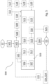
- a method 500 for controlling a braking system of a vehicle according to the present invention will now be described with reference to the aforesaid figures and to the block chart in figure 5 .
- the method 500 comprises a symbolic step of starting ST.
- a method 500 comprises a step of detecting 501, by a first plurality 101 of detection devices distributed on the braking system of the vehicle, first information I1 representative of a condition of motion of the vehicle.
- the first plurality 101 of detection devices and the first information I1 representative of a motion condition of the vehicle have already been previously defined and described.
- the method 500 further comprises a step of detecting 502, by a second plurality 103 of detection devices belonging to a first driver assistance sub-system 102 associated with the vehicle, second information I2 representative of a condition of motion of the vehicle.
- the second plurality 103 of detection devices and the second information I2 representative of a condition of motion of the vehicle have already been previously defined and described.
- the method 500 comprises a step of determining 503, by a first data processing block 105, a first control signal SC1 of a braking module 104 of the vehicle based on said first information I1 and said second information I2.
- the first data processing block 105 and the braking module 104 have been previously defined and described.
- the method 500 further comprises a step of controlling 504, by the first data processing block 105, the braking module 104 of the vehicle based on the determined first control signal SC1.
- the method 500 comprises a symbolic step of ending ED.
- the method 500 further comprises a step of providing 505, by the first plurality 101 of detection devices, said second information I2 directly to the first data processing block 105.
- the step of determining 503 is performed by the first data processing block 105, directly on the basis of the first information I1 and of the second information I2.
- the step of determining 503 comprises a respective first step of checking 506, by the first data processing block 105, if said first information I1 is representative of a first stopped vehicle condition.
- the first information I1 is checked as representative of a first stopped vehicle condition when the first stopped vehicle condition is maintained for a set first interval of time.
- the first data processing block 105 estimates a vehicle speed equal to a value which is substantially zero or very close to 0 and if the vehicle speed assumes this substantially zero value (in a further embodiment, also for a first set interval of time equal to one or more seconds), the first data processing block 105 had checked the presence of a first stopped vehicle condition.
- a detection device of said first plurality 101 e.g. a rotation speed sensor of a vehicle wheel
- the first data processing block 105 estimates a vehicle speed equal to a value which is substantially zero or very close to 0 and if the vehicle speed assumes this substantially zero value (in a further embodiment, also for a first set interval of time equal to one or more seconds), the first data processing block 105 had checked the presence of a first stopped vehicle condition.
- the aforesaid estimate consists, for example, in comparing the speed of the vehicle with a respective threshold value (e.g. number of signals/time) and if the vehicle speed is lower than the respective threshold value then the vehicle speed is estimated to be equal to 0.
- a respective threshold value e.g. number of signals/time
- the step of determining 503 comprises a respective second step of checking 507, by the first data processing block 105, if said second information I2 is representative of a second stopped vehicle condition.
- the second information I2 is checked as representative of a second stopped vehicle condition when the second stopped vehicle condition is maintained for a set second interval of time.
- the first data processing block 105 estimates a vehicle speed equal to a value which is substantially zero or very close to 0 and if the vehicle speed assumes this substantially zero value (in a further embodiment, also for a second set interval of time equal to one or more seconds), the second data processing block 105 had checked the presence of a second stopped vehicle condition.
- the aforesaid estimate consists, for example, in comparing the speed of the vehicle with a respective threshold value (e.g. number of signals/time) and if the vehicle speed is lower than the respective threshold value then the vehicle speed is estimated to be equal to 0.
- a respective threshold value e.g. number of signals/time
- the checking, by the first data processing block 105, of both the first stopped vehicle condition and of the second stopped vehicle condition implies the definitive determination, by the first data processing block 105, of the first control signal SC1 of the vehicle braking module 104.
- the first control signal SC1 on the basis of which to check, by means of the first processing block 105, the braking module 104 of the vehicle comprises an inhibiting signal for the activation of the braking module 104 of the vehicle which will not be able to apply any braking action (electric park or service brake, according to the typology of the vehicle braking module 104) on the vehicle.
- the first control signal SC1 comprises an activation signal of the vehicle braking module 104 which can apply a braking action (electric park or service brake, according to the type of vehicle braking module 104) on the vehicle.
- the method 500 further comprises a step of providing 508, by the second plurality 103 of detection devices, said second information I2 directly to a second data processing block 106.
- the second data processing block 106 was previously defined and described.
- the method 500 further comprises a step of determining 509, by the second data processing block 106, further second information I2' representative of a condition of motion of the vehicle based on said second information I2.
- the second data processing block 106 determines the further second information I2' by decoding and aggregating the second information I2 to make them more reliable (e.g. the same information received from multiple sensors) and then the brake controller decides what to do according to its own information plus that provided by the VCS.
- the method 500 comprises a step of providing 510, by the second data processing block 106, said further second information I2' to the first data processing block 106.
- the step of determining 503 the first control signal SC1 of the braking module 104 of the vehicle is performed by the first data processing block 105 based on said first information I1 and said further second information I2'.
- the step of determining 503 comprises a respective first step of checking 511, by the first data processing block 105, if said first information I1 is representative of a first stopped vehicle condition.
- the first information I1 is checked as representative of a first stopped vehicle condition when the first stopped vehicle condition is maintained for a set first interval of time.
- this first step of checking 511 is entirely similar to the example of the implementation of the first step of checking 506, previously described.
- the step of determining 503 comprises a respective second step of checking 512, by the first data processing block 105, whether said further second information I2' is representative of a second stopped vehicle condition.
- the further second information I2' is checked as representative of a second stopped vehicle condition when the second stopped vehicle condition is maintained for a set second interval of time.
- the first data processing block 105 estimates a vehicle speed equal to a value which is substantially zero or very close to 0 and if the vehicle speed assumes this substantially zero value (in a further embodiment, also for a second set interval of time equal to one or more seconds), the second data processing block 105 had checked the presence of the second stopped vehicle condition.
- the aforesaid estimate consists, for example, in comparing the speed of the vehicle with a respective threshold value (e.g. number of signals/time) and if the vehicle speed is lower than the respective threshold value then the vehicle speed is estimated to be equal to 0.
- a respective threshold value e.g. number of signals/time
- the checking by the first data processing block 105, both in the first stopped vehicle condition and in the second stopped vehicle condition, implies the definitive determination, by the first data processing block 105, of the first control signal SC1 of the vehicle braking module 104, i.e. an inhibition signal of the activation of the vehicle braking module 104 which will not be able to apply any braking action (electric park or service braking, according to the type of the vehicle braking module 104) on the vehicle.
- the first control signal SC1 comprises an activation signal of the vehicle braking module 104 which can apply a braking action (electric park or service brake, according to the type of vehicle braking module 104) on the vehicle.
- the method 500 further comprises a step of detecting 513, by a third plurality 108 of detection devices belonging to a second vehicle data connection sub-system 107, third information I3 representative of a condition of motion of the vehicle.
- the third plurality 108 of detection devices, the second vehicle data connection sub-system 107 and the third information I3 were previously defined and described.
- the step of determining 503 the first control signal SC1 of the braking module 104 of the vehicle is performed by the first data processing block 105 based on said first information I1, said further second information I2' and said third information I3.
- the step of determining 503 comprises a respective first step of checking 514, by the first data processing block 105, if said first information I1 is representative of a first stopped vehicle condition.
- the first information I1 is checked as representative of a first stopped vehicle condition when the first stopped vehicle condition is maintained for a set first interval of time.
- this first step of checking 514 is entirely similar to the example of the implementation of the first step of checking 506, previously described.
- the step of determining 503 comprises a respective second step of checking 515, by the first data processing block 105, if said second information I2 is representative of a second stopped vehicle condition.
- the second information I2 is checked as representative of a second stopped vehicle condition when the second stopped vehicle condition is maintained for a set second interval of time.
- this second step of checking 515 is entirely similar to the example of the implementation of the second step of checking 507, previously described.
- the step of determining 503 further comprises a respective third step of checking 516, by the first data processing block 105, whether said second information I3 is representative of a third stopped vehicle condition.
- the third information I3 is checked as representative of a third stopped vehicle condition when the third stopped vehicle condition is maintained for a set third interval of time.
- the first data processing block 105 on the base of the further third information I3 estimates a vehicle speed equal to a value which is substantially zero or very close to 0 and if the vehicle speed assumes this substantially zero value (in a further embodiment, also for a second set interval of time, e.g. equal to one or more seconds), the first data processing block 105 had checked the presence of the third stopped vehicle condition.
- a detection device of said third plurality 108 e.g. a V2V type communication module, indicates that the vehicle has stopped (e.g. a constant distance from a preceding vehicle is detected)
- the first data processing block 105 on the base of the further third information I3 estimates a vehicle speed equal to a value which is substantially zero or very close to 0 and if the vehicle speed assumes this substantially zero value (in a further embodiment, also for a second set interval of time, e.g. equal to one or more seconds), the first data processing block 105 had checked the presence of the third stopped vehicle condition.
- the aforesaid estimate consists, for example, in comparing the speed of the vehicle with the speed of the vehicle ahead and if the speed of the vehicle and the speed of the vehicle ahead are equal to 0 then the speed of the vehicle is estimated to be equal to 0.
- the checking, by the first data processing block 105, of the first stopped vehicle condition, the second stopped vehicle condition and the third stopped vehicle condition implies the definitive determination, by the first data processing block 105, of the first control signal SC1 of the module 104 of the vehicle, i.e. an inhibition signal of the activation of the vehicle braking module 104 which will not be able to apply any braking action (electric park or service braking, according to the typology of the vehicle braking module 104) on the vehicle.
- the first control signal SC1 comprises an activation signal of the vehicle braking module 104 which can apply a braking action (electric park or service brake, according to the type of vehicle braking module 104) on the vehicle.
- the method 500 comprises a step of detecting 517, by a third plurality 108 of detection devices belonging to a second vehicle data connection sub-system 107, third information I3 representative of a condition of motion of the vehicle.
- the third plurality 108 of detection devices, the second vehicle data connection sub-system 107 and the third information I3 were previously defined and described with reference to other embodiments.
- the method 500 further comprises a step of providing 518, by the third plurality 108 of detection devices, said third information I3 directly to a second data processing block 106.
- the second data processing block 106 were previously described with reference to other embodiments.
- the method 500 further comprises a step of determining 519, by the second data processing block 106, fourth information I4 representative of a condition of motion of the vehicle based on said second information I2 and said third information I3.
- Such a processing is obtained, for example, by checking that the second information I2 is within a respective threshold and that the third information I3 is within a respective threshold.
- the method 500 comprises a step of providing 520, by the second data processing block 106, said fourth information I4 to the first data processing block 105.
- the step of determining 503 the first control signal SC1 of the braking module 104 of the vehicle is performed by the first data processing block 105 on the basis of said first information I1 and said fourth information I4 (which depends on said second information I2).
- the step of determining 503 comprises a respective first step of checking 521, by the first data processing block 105, if said first information I1 is representative of a first stopped vehicle condition.
- the first information I1 is checked as representative of a first stopped vehicle condition when the first stopped vehicle condition is maintained for a set first interval of time.
- this first step of checking 521 is entirely similar to the example of the implementation of the first step of checking 506, previously described.
- the step of determining 503 comprises a respective second step of checking 522, by the first data processing block 105, whether said fourth information I4 is representative of a second stopped vehicle condition.
- the fourth information I4 is checked as representative of a second stopped vehicle condition when the second stopped vehicle condition is maintained for a set second interval of time.
- this second step of checking 515 is entirely similar to the example of the implementation of the second step of checking 507, previously described.
- a detection device of said second plurality 103 e.g. a digital camera
- a detection device of said third plurality 108 e.g.
- a V2V type communication module indicates in turn that the vehicle has stopped (in the manner show above, for example), the first data processing block 105, on the base of the further fourth information I4 provided by the second data processing block 106, estimates (in the manner described above, for example) a vehicle speed equal to a value which is substantially zero or very close to 0 and if the vehicle speed assumes this substantially zero value (in a further embodiment, also for a second set interval of time equal to one or more seconds), the second data processing block 105 had checked the presence of the second stopped vehicle condition.
- the checking by the first data processing block 105 of the first stopped vehicle condition and the second stopped vehicle condition implies the definitive determination, by the first data processing block 105, of the first control signal SC1 of the vehicle braking module 104 or an inhibition signal of the activation of the vehicle braking module 104 which will not be able to apply any braking action (electric park or service braking, according to the type of vehicle braking module 104) on the vehicle.
- the first control signal SC1 comprises an activation signal of the vehicle braking module 104 which can apply a braking action (electric park or service brake, according to the type of vehicle braking module 104) on the vehicle.
- the method 500 further comprises the steps of:
- the safe or unsafe condition of the vehicle is identified by the first data processing block 105 based on said first information I1 and further second information I2' provided by a second data processing block 106 (previously described).
- the safe or unsafe condition of the vehicle is identified by the first data processing block 105 based on said first information I1, of said second information I2 and of third information I3 representative of a condition of motion of the vehicle detected by a third plurality 108 of detection devices belonging to a second data connection sub-system 107 of the vehicle (previously described).
- the safe or unsafe condition of the vehicle is identified by the first data processing block 105 based on said first information I1 and fourth information I4 representative of a condition of motion of the vehicle (previously described) determined by a second data processing block 106 based on said second information I2 and said third information I3.
- condition of motion of the vehicle may be determined on the basis of said first information I1 and of said further second information I2' (if the second data processing block 106 present) or on the basis of said first information I1 and said fourth information I4 (if the second data processing block 106 is present).
- the first data processing block 105 provides the second control signal SC2 to the service braking module 109.
- the method 500 further comprises a step of providing 525, by the first information block 105, one or more further control signals SCN to the service braking module 109 to perform further operations on the braking system or on the vehicle in general, e.g., cleaning the brake discs from rust or water, improving the load distribution on the motion components (wheels) and so forth.
- the method and the related system according to the present invention advantageously allows to duplicate the first information I1 detected by the detection devices distributed in the braking system with the second information I2 detected by the detection devices present aboard the vehicle in the first driver assistance sub-system 102 associated with the vehicle or ADAS (Advanced Driver-Assistance System) sub-system.
- ADAS Advanced Driver-Assistance System
- the aforesaid information may be made further duplicated by the third information I3 which can be detected by the detection devices belonging to a second vehicle data connection sub-system 107, thus advantageously increasing the safety level of the system, thus the vehicle.
- ADAS ADAS
- the use of the information available from the second vehicle data connection sub-system 107 advantageously allows to simplify the architecture and the configuration of the park brake module of EPB type, thus ensuring a greater safety in situations of faults of the sensors traditionally used.
- a vehicle equipped with a sub-system of the ADAS type can exploit the measurements performed by the detection devices of such a sub-system as braking module input information (e.g. EPB type, thus duplicating the information coming from the detection devices distributed in the braking system of the vehicle, e.g. speed sensors of the four wheels of the vehicle).
- braking module input information e.g. EPB type
- the detection devices which can be used by the braking module are multiple and external to the braking system of the vehicle so as to differentiate the signal sources further and advantageously increase safety in the event of failure of one or more of the detection devices.
- a vehicle provided with a data connection sub-system can exploit the information relating to the vehicle condition as a further input information for the braking module (e.g. EPB), duplicating the information of the detection devices distributed in the braking system and those belonging to the ADAS sub-system.
- the braking module e.g. EPB
- the method and the related system according to the present invention also allow to combine the first information detected by the detection devices distributed in the braking system with the second information detected by the detection devices belonging to the first sub-system 102 (ADAS) and the third information I3 detected by the detection devices belonging to the second data connection sub-system 107 of the vehicle to control the total residual torque of the vehicle advantageously in an active manner and reduce it in appropriate conditions (e.g. in a safe condition of the vehicle), thus reducing the mechanical losses due to residual torque of the brakes and increasing the overall efficiency of the vehicle.
- ADAS first sub-system 102
- the method and system according to the present invention indeed allow such an active control (reduction) of the residual torque in a safe condition of the vehicle, i.e. the condition in which the vehicle is far from possible/probable braking events, identified by combining the first information I1 detected by the detection devices distributed in the vehicle braking system with the second information I2 detected by the detection devices belonging to the first sub-system 102 (ADAS) and the third information I3 detected by the detection devices belonging to the second vehicle data connection sub-system 107 (e.g. GPS location and maps, programmed route, information from another vehicle - V2V - or by other infrastructure V2X).
- ADAS first sub-system 102
- the third information I3 detected by the detection devices belonging to the second vehicle data connection sub-system 107 e.g. GPS location and maps, programmed route, information from another vehicle - V2V - or by other infrastructure V2X.
- the method and the related system of the present invention can also be used to reduce the residual torque even with traditional braking systems or electro-hydraulic braking systems equipped with ESP with adaptive functions or logic, i.e. with the possibility of controlling the gap between brake pad and brake disc.
Landscapes
- Engineering & Computer Science (AREA)
- Transportation (AREA)
- Mechanical Engineering (AREA)
- Regulating Braking Force (AREA)
- Braking Arrangements (AREA)
Applications Claiming Priority (2)
| Application Number | Priority Date | Filing Date | Title |
|---|---|---|---|
| IT102018000005950A IT201800005950A1 (it) | 2018-06-01 | 2018-06-01 | Metodo di controllo di un impianto frenante di un veicolo e relativo sistema |
| PCT/IB2019/054396 WO2019229641A1 (en) | 2018-06-01 | 2019-05-28 | Method for controlling a braking system of a vehicle and related system |
Publications (2)
| Publication Number | Publication Date |
|---|---|
| EP3802245A1 EP3802245A1 (en) | 2021-04-14 |
| EP3802245B1 true EP3802245B1 (en) | 2025-04-23 |
Family
ID=63579593
Family Applications (1)
| Application Number | Title | Priority Date | Filing Date |
|---|---|---|---|
| EP19731349.7A Active EP3802245B1 (en) | 2018-06-01 | 2019-05-28 | Method for controlling a braking system of a vehicle and related system |
Country Status (6)
| Country | Link |
|---|---|
| US (1) | US20210221341A1 (https=) |
| EP (1) | EP3802245B1 (https=) |
| JP (2) | JP2021525676A (https=) |
| CN (1) | CN112533803A (https=) |
| IT (1) | IT201800005950A1 (https=) |
| WO (1) | WO2019229641A1 (https=) |
Families Citing this family (3)
| Publication number | Priority date | Publication date | Assignee | Title |
|---|---|---|---|---|
| US11479249B2 (en) * | 2018-10-10 | 2022-10-25 | Waterblasting, Llc | Speed control system for road equipment |
| US11718287B2 (en) * | 2020-12-09 | 2023-08-08 | Bendix Commercial Vehicle Systems Llc | Automated system and method for parking a commercial vehicle |
| US12071119B2 (en) * | 2021-02-24 | 2024-08-27 | Textron Innovations Inc. | Emergency vehicle braking using closed-loop pulsing |
Family Cites Families (14)
| Publication number | Priority date | Publication date | Assignee | Title |
|---|---|---|---|---|
| US6904350B2 (en) * | 2000-09-25 | 2005-06-07 | Ford Global Technologies, Llc | System for dynamically determining the wheel grounding and wheel lifting conditions and their applications in roll stability control |
| JP2009051403A (ja) * | 2007-08-28 | 2009-03-12 | Denso Corp | 車両用制御装置及び制御システム |
| JP4671242B2 (ja) * | 2008-02-15 | 2011-04-13 | 関東自動車工業株式会社 | 車両制御装置 |
| WO2011096938A1 (en) * | 2010-02-08 | 2011-08-11 | Ford Global Technologies, Llc | Externally-controllable vehicle parking features |
| DE102011080431A1 (de) * | 2011-08-04 | 2013-02-07 | Robert Bosch Gmbh | Steuervorrichtung für ein Bremssystem eines Fahrzeugs, Bremssystem für ein Fahrzeug und Verfahren zum Betreiben eines Bremssystems eines Fahrzeugs |
| US10737665B2 (en) * | 2012-08-28 | 2020-08-11 | Ford Global Technologies, Llc | Vehicle braking based on external object communications |
| JP5856941B2 (ja) * | 2012-10-24 | 2016-02-10 | オムロンオートモーティブエレクトロニクス株式会社 | 車速検出システムおよび車両用制御装置 |
| DE102013200793A1 (de) * | 2013-01-18 | 2014-07-24 | Robert Bosch Gmbh | Fahrerassistenzsystem |
| CN103863293A (zh) * | 2013-08-12 | 2014-06-18 | 中国科学院合肥物质科学研究院 | 一种车辆驻车制动系统及其控制方法 |
| JP6175025B2 (ja) * | 2014-05-23 | 2017-08-02 | 本田技研工業株式会社 | 物体認識装置 |
| SE539021C2 (sv) * | 2014-08-13 | 2017-03-21 | Scania Cv Ab | System och förfarande för förhindrande av oönskad rörelse hos ett motorfordonsekipage |
| JP6332180B2 (ja) * | 2015-07-15 | 2018-05-30 | トヨタ自動車株式会社 | 車両の制御装置 |
| JP2017134520A (ja) * | 2016-01-26 | 2017-08-03 | トヨタ自動車株式会社 | 車両用衝突回避支援システム |
| EP3315369B1 (en) * | 2016-10-25 | 2021-03-03 | KNORR-BREMSE Systeme für Nutzfahrzeuge GmbH | Apparatus and method for controlling a traction of a vehicle |
-
2018
- 2018-06-01 IT IT102018000005950A patent/IT201800005950A1/it unknown
-
2019
- 2019-05-28 JP JP2020567017A patent/JP2021525676A/ja active Pending
- 2019-05-28 WO PCT/IB2019/054396 patent/WO2019229641A1/en not_active Ceased
- 2019-05-28 US US15/733,938 patent/US20210221341A1/en active Pending
- 2019-05-28 EP EP19731349.7A patent/EP3802245B1/en active Active
- 2019-05-28 CN CN201980051337.6A patent/CN112533803A/zh active Pending
-
2024
- 2024-12-26 JP JP2024230256A patent/JP2025041927A/ja active Pending
Also Published As
| Publication number | Publication date |
|---|---|
| CN112533803A (zh) | 2021-03-19 |
| JP2025041927A (ja) | 2025-03-26 |
| IT201800005950A1 (it) | 2019-12-01 |
| EP3802245A1 (en) | 2021-04-14 |
| WO2019229641A1 (en) | 2019-12-05 |
| JP2021525676A (ja) | 2021-09-27 |
| US20210221341A1 (en) | 2021-07-22 |
Similar Documents
| Publication | Publication Date | Title |
|---|---|---|
| US9145114B2 (en) | Method for ensuring a braking effect | |
| JP2025041927A (ja) | 車両のブレーキシステム及び関連システムを制御する方法 | |
| JP5769182B2 (ja) | 車両のブレーキシステムの作用監視のための方法および装置 | |
| CN103072574A (zh) | 防撞系统及其操作方法 | |
| CN111605525A (zh) | 一种基于实时路面识别的紧急自动刹车稳态控制方法 | |
| CN106184161A (zh) | 用于利用自动的停车制动器来对车辆进行保护的方法 | |
| US20180072292A1 (en) | Vehicle automatic emergency braking system | |
| CN113942485B (zh) | 制动垫片状态推断装置和制动垫片状态推断方法 | |
| CN103038109A (zh) | 自动预防浮滑的方法 | |
| CN104554215A (zh) | 驾驶员辅助系统 | |
| JP2012532060A (ja) | 道路車両において自発的な非常制動を正確に実行する方法 | |
| US20100262368A1 (en) | Brake Controller Utilizing a Global Positioning System | |
| US12252107B2 (en) | Method and control unit for operating a tractor-trailer combination made up of a towing vehicle and a trailer including an overrun brake | |
| CN112061125B (zh) | 用于动态适配车辆之间的纵向距离的方法 | |
| US20200201341A1 (en) | Method for Operating an Automated Vehicle | |
| CN116811877A (zh) | 计算机实现的方法、电子设备和机器可读介质 | |
| CN109421687B (zh) | 制动系统延时自学习方法以及计算机可读存储介质 | |
| KR102881710B1 (ko) | 운전자 보조 시스템 및 그 제어 방법 | |
| US9539992B2 (en) | Method for operating an electromechanical vehicle brake system | |
| US11273823B2 (en) | Method for determining a maximum speed of a vehicle during a parking maneuver | |
| JP2021525676A5 (https=) | ||
| CN116761750A (zh) | 用于使车辆接近装卸台的方法、控制装置以及车辆 | |
| KR20180113637A (ko) | 곡선로 주행과 관련하여 도로에서 차량의 운행의 적응화를 위한 방법 및 시스템 | |
| US10046766B2 (en) | Traction loss warning system and method | |
| US11091154B2 (en) | Method and apparatus for rapid stopping of a motor vehicle particularly on snow or ice |
Legal Events
| Date | Code | Title | Description |
|---|---|---|---|
| STAA | Information on the status of an ep patent application or granted ep patent |
Free format text: STATUS: UNKNOWN |
|
| STAA | Information on the status of an ep patent application or granted ep patent |
Free format text: STATUS: THE INTERNATIONAL PUBLICATION HAS BEEN MADE |
|
| PUAI | Public reference made under article 153(3) epc to a published international application that has entered the european phase |
Free format text: ORIGINAL CODE: 0009012 |
|
| STAA | Information on the status of an ep patent application or granted ep patent |
Free format text: STATUS: REQUEST FOR EXAMINATION WAS MADE |
|
| 17P | Request for examination filed |
Effective date: 20201214 |
|
| AK | Designated contracting states |
Kind code of ref document: A1 Designated state(s): AL AT BE BG CH CY CZ DE DK EE ES FI FR GB GR HR HU IE IS IT LI LT LU LV MC MK MT NL NO PL PT RO RS SE SI SK SM TR |
|
| AX | Request for extension of the european patent |
Extension state: BA ME |
|
| RAP3 | Party data changed (applicant data changed or rights of an application transferred) |
Owner name: BREMBO S.P.A. |
|
| RIN1 | Information on inventor provided before grant (corrected) |
Inventor name: GALIZZI, VALERIO Inventor name: DI STEFANO, MASSIMO Inventor name: UGOLINI, LUCA Inventor name: FORNI, FABRIZIO Inventor name: CAMOZZI, FRANCESCO |
|
| RAP3 | Party data changed (applicant data changed or rights of an application transferred) |
Owner name: BREMBO S.P.A. |
|
| DAV | Request for validation of the european patent (deleted) | ||
| DAX | Request for extension of the european patent (deleted) | ||
| STAA | Information on the status of an ep patent application or granted ep patent |
Free format text: STATUS: EXAMINATION IS IN PROGRESS |
|
| 17Q | First examination report despatched |
Effective date: 20230329 |
|
| P01 | Opt-out of the competence of the unified patent court (upc) registered |
Effective date: 20230526 |
|
| GRAP | Despatch of communication of intention to grant a patent |
Free format text: ORIGINAL CODE: EPIDOSNIGR1 |
|
| STAA | Information on the status of an ep patent application or granted ep patent |
Free format text: STATUS: GRANT OF PATENT IS INTENDED |
|
| INTG | Intention to grant announced |
Effective date: 20241220 |
|
| GRAS | Grant fee paid |
Free format text: ORIGINAL CODE: EPIDOSNIGR3 |
|
| GRAA | (expected) grant |
Free format text: ORIGINAL CODE: 0009210 |
|
| STAA | Information on the status of an ep patent application or granted ep patent |
Free format text: STATUS: THE PATENT HAS BEEN GRANTED |
|
| AK | Designated contracting states |
Kind code of ref document: B1 Designated state(s): AL AT BE BG CH CY CZ DE DK EE ES FI FR GB GR HR HU IE IS IT LI LT LU LV MC MK MT NL NO PL PT RO RS SE SI SK SM TR |
|
| REG | Reference to a national code |
Ref country code: GB Ref legal event code: FG4D |
|
| REG | Reference to a national code |
Ref country code: CH Ref legal event code: EP |
|
| REG | Reference to a national code |
Ref country code: DE Ref legal event code: R096 Ref document number: 602019068984 Country of ref document: DE |
|
| REG | Reference to a national code |
Ref country code: IE Ref legal event code: FG4D |
|
| REG | Reference to a national code |
Ref country code: NL Ref legal event code: MP Effective date: 20250423 |
|
| PG25 | Lapsed in a contracting state [announced via postgrant information from national office to epo] |
Ref country code: NL Free format text: LAPSE BECAUSE OF FAILURE TO SUBMIT A TRANSLATION OF THE DESCRIPTION OR TO PAY THE FEE WITHIN THE PRESCRIBED TIME-LIMIT Effective date: 20250423 |
|
| REG | Reference to a national code |
Ref country code: AT Ref legal event code: MK05 Ref document number: 1787503 Country of ref document: AT Kind code of ref document: T Effective date: 20250423 |
|
| PG25 | Lapsed in a contracting state [announced via postgrant information from national office to epo] |
Ref country code: ES Free format text: LAPSE BECAUSE OF FAILURE TO SUBMIT A TRANSLATION OF THE DESCRIPTION OR TO PAY THE FEE WITHIN THE PRESCRIBED TIME-LIMIT Effective date: 20250423 Ref country code: FI Free format text: LAPSE BECAUSE OF FAILURE TO SUBMIT A TRANSLATION OF THE DESCRIPTION OR TO PAY THE FEE WITHIN THE PRESCRIBED TIME-LIMIT Effective date: 20250423 Ref country code: PT Free format text: LAPSE BECAUSE OF FAILURE TO SUBMIT A TRANSLATION OF THE DESCRIPTION OR TO PAY THE FEE WITHIN THE PRESCRIBED TIME-LIMIT Effective date: 20250825 |
|
| PGFP | Annual fee paid to national office [announced via postgrant information from national office to epo] |
Ref country code: DE Payment date: 20250717 Year of fee payment: 7 |
|
| REG | Reference to a national code |
Ref country code: LT Ref legal event code: MG9D |
|
| PG25 | Lapsed in a contracting state [announced via postgrant information from national office to epo] |
Ref country code: GR Free format text: LAPSE BECAUSE OF FAILURE TO SUBMIT A TRANSLATION OF THE DESCRIPTION OR TO PAY THE FEE WITHIN THE PRESCRIBED TIME-LIMIT Effective date: 20250724 Ref country code: NO Free format text: LAPSE BECAUSE OF FAILURE TO SUBMIT A TRANSLATION OF THE DESCRIPTION OR TO PAY THE FEE WITHIN THE PRESCRIBED TIME-LIMIT Effective date: 20250723 |
|
| PG25 | Lapsed in a contracting state [announced via postgrant information from national office to epo] |
Ref country code: PL Free format text: LAPSE BECAUSE OF FAILURE TO SUBMIT A TRANSLATION OF THE DESCRIPTION OR TO PAY THE FEE WITHIN THE PRESCRIBED TIME-LIMIT Effective date: 20250423 |
|
| PG25 | Lapsed in a contracting state [announced via postgrant information from national office to epo] |
Ref country code: BG Free format text: LAPSE BECAUSE OF FAILURE TO SUBMIT A TRANSLATION OF THE DESCRIPTION OR TO PAY THE FEE WITHIN THE PRESCRIBED TIME-LIMIT Effective date: 20250423 |
|
| PGFP | Annual fee paid to national office [announced via postgrant information from national office to epo] |
Ref country code: GB Payment date: 20250722 Year of fee payment: 7 |
|
| PG25 | Lapsed in a contracting state [announced via postgrant information from national office to epo] |
Ref country code: HR Free format text: LAPSE BECAUSE OF FAILURE TO SUBMIT A TRANSLATION OF THE DESCRIPTION OR TO PAY THE FEE WITHIN THE PRESCRIBED TIME-LIMIT Effective date: 20250423 |
|
| PG25 | Lapsed in a contracting state [announced via postgrant information from national office to epo] |
Ref country code: AT Free format text: LAPSE BECAUSE OF FAILURE TO SUBMIT A TRANSLATION OF THE DESCRIPTION OR TO PAY THE FEE WITHIN THE PRESCRIBED TIME-LIMIT Effective date: 20250423 |
|
| PGFP | Annual fee paid to national office [announced via postgrant information from national office to epo] |
Ref country code: FR Payment date: 20250731 Year of fee payment: 7 |
|
| PG25 | Lapsed in a contracting state [announced via postgrant information from national office to epo] |
Ref country code: RS Free format text: LAPSE BECAUSE OF FAILURE TO SUBMIT A TRANSLATION OF THE DESCRIPTION OR TO PAY THE FEE WITHIN THE PRESCRIBED TIME-LIMIT Effective date: 20250723 |
|
| PG25 | Lapsed in a contracting state [announced via postgrant information from national office to epo] |
Ref country code: IS Free format text: LAPSE BECAUSE OF FAILURE TO SUBMIT A TRANSLATION OF THE DESCRIPTION OR TO PAY THE FEE WITHIN THE PRESCRIBED TIME-LIMIT Effective date: 20250823 |
|
| PG25 | Lapsed in a contracting state [announced via postgrant information from national office to epo] |
Ref country code: LV Free format text: LAPSE BECAUSE OF FAILURE TO SUBMIT A TRANSLATION OF THE DESCRIPTION OR TO PAY THE FEE WITHIN THE PRESCRIBED TIME-LIMIT Effective date: 20250423 |
|
| REG | Reference to a national code |
Ref country code: CH Ref legal event code: H13 Free format text: ST27 STATUS EVENT CODE: U-0-0-H10-H13 (AS PROVIDED BY THE NATIONAL OFFICE) Effective date: 20251223 |
|
| PG25 | Lapsed in a contracting state [announced via postgrant information from national office to epo] |
Ref country code: SM Free format text: LAPSE BECAUSE OF FAILURE TO SUBMIT A TRANSLATION OF THE DESCRIPTION OR TO PAY THE FEE WITHIN THE PRESCRIBED TIME-LIMIT Effective date: 20250423 Ref country code: DK Free format text: LAPSE BECAUSE OF FAILURE TO SUBMIT A TRANSLATION OF THE DESCRIPTION OR TO PAY THE FEE WITHIN THE PRESCRIBED TIME-LIMIT Effective date: 20250423 |
|
| PG25 | Lapsed in a contracting state [announced via postgrant information from national office to epo] |
Ref country code: LU Free format text: LAPSE BECAUSE OF NON-PAYMENT OF DUE FEES Effective date: 20250528 |
|
| PG25 | Lapsed in a contracting state [announced via postgrant information from national office to epo] |
Ref country code: CH Free format text: LAPSE BECAUSE OF NON-PAYMENT OF DUE FEES Effective date: 20250531 |
|
| PG25 | Lapsed in a contracting state [announced via postgrant information from national office to epo] |
Ref country code: CZ Free format text: LAPSE BECAUSE OF FAILURE TO SUBMIT A TRANSLATION OF THE DESCRIPTION OR TO PAY THE FEE WITHIN THE PRESCRIBED TIME-LIMIT Effective date: 20250423 |
|
| PG25 | Lapsed in a contracting state [announced via postgrant information from national office to epo] |
Ref country code: EE Free format text: LAPSE BECAUSE OF FAILURE TO SUBMIT A TRANSLATION OF THE DESCRIPTION OR TO PAY THE FEE WITHIN THE PRESCRIBED TIME-LIMIT Effective date: 20250423 |
|
| REG | Reference to a national code |
Ref country code: DE Ref legal event code: R097 Ref document number: 602019068984 Country of ref document: DE |
|
| PG25 | Lapsed in a contracting state [announced via postgrant information from national office to epo] |
Ref country code: SK Free format text: LAPSE BECAUSE OF FAILURE TO SUBMIT A TRANSLATION OF THE DESCRIPTION OR TO PAY THE FEE WITHIN THE PRESCRIBED TIME-LIMIT Effective date: 20250423 Ref country code: RO Free format text: LAPSE BECAUSE OF FAILURE TO SUBMIT A TRANSLATION OF THE DESCRIPTION OR TO PAY THE FEE WITHIN THE PRESCRIBED TIME-LIMIT Effective date: 20250423 |
|
| PG25 | Lapsed in a contracting state [announced via postgrant information from national office to epo] |
Ref country code: IT Free format text: LAPSE BECAUSE OF FAILURE TO SUBMIT A TRANSLATION OF THE DESCRIPTION OR TO PAY THE FEE WITHIN THE PRESCRIBED TIME-LIMIT Effective date: 20250423 |
|
| REG | Reference to a national code |
Ref country code: BE Ref legal event code: MM Effective date: 20250531 |
|
| PG25 | Lapsed in a contracting state [announced via postgrant information from national office to epo] |
Ref country code: MC Free format text: LAPSE BECAUSE OF FAILURE TO SUBMIT A TRANSLATION OF THE DESCRIPTION OR TO PAY THE FEE WITHIN THE PRESCRIBED TIME-LIMIT Effective date: 20250423 |
|
| PLBE | No opposition filed within time limit |
Free format text: ORIGINAL CODE: 0009261 |
|
| STAA | Information on the status of an ep patent application or granted ep patent |
Free format text: STATUS: NO OPPOSITION FILED WITHIN TIME LIMIT |
|
| REG | Reference to a national code |
Ref country code: CH Ref legal event code: L10 Free format text: ST27 STATUS EVENT CODE: U-0-0-L10-L00 (AS PROVIDED BY THE NATIONAL OFFICE) Effective date: 20260304 |
|
| 26N | No opposition filed |
Effective date: 20260126 |
|
| PG25 | Lapsed in a contracting state [announced via postgrant information from national office to epo] |
Ref country code: IE Free format text: LAPSE BECAUSE OF NON-PAYMENT OF DUE FEES Effective date: 20250528 |
|
| PG25 | Lapsed in a contracting state [announced via postgrant information from national office to epo] |
Ref country code: BE Free format text: LAPSE BECAUSE OF NON-PAYMENT OF DUE FEES Effective date: 20250531 |