US11479249B2 - Speed control system for road equipment - Google Patents
Speed control system for road equipment Download PDFInfo
- Publication number
- US11479249B2 US11479249B2 US16/156,469 US201816156469A US11479249B2 US 11479249 B2 US11479249 B2 US 11479249B2 US 201816156469 A US201816156469 A US 201816156469A US 11479249 B2 US11479249 B2 US 11479249B2
- Authority
- US
- United States
- Prior art keywords
- air
- brake
- work vehicle
- speed
- speed control
- Prior art date
- Legal status (The legal status is an assumption and is not a legal conclusion. Google has not performed a legal analysis and makes no representation as to the accuracy of the status listed.)
- Active, expires
Links
Images


Classifications
-
- B—PERFORMING OPERATIONS; TRANSPORTING
- B60—VEHICLES IN GENERAL
- B60T—VEHICLE BRAKE CONTROL SYSTEMS OR PARTS THEREOF; BRAKE CONTROL SYSTEMS OR PARTS THEREOF, IN GENERAL; ARRANGEMENT OF BRAKING ELEMENTS ON VEHICLES IN GENERAL; PORTABLE DEVICES FOR PREVENTING UNWANTED MOVEMENT OF VEHICLES; VEHICLE MODIFICATIONS TO FACILITATE COOLING OF BRAKES
- B60T1/00—Arrangements of braking elements, i.e. of those parts where braking effect occurs specially for vehicles
- B60T1/02—Arrangements of braking elements, i.e. of those parts where braking effect occurs specially for vehicles acting by retarding wheels
- B60T1/06—Arrangements of braking elements, i.e. of those parts where braking effect occurs specially for vehicles acting by retarding wheels acting otherwise than on tread, e.g. employing rim, drum, disc, or transmission or on double wheels
- B60T1/062—Arrangements of braking elements, i.e. of those parts where braking effect occurs specially for vehicles acting by retarding wheels acting otherwise than on tread, e.g. employing rim, drum, disc, or transmission or on double wheels acting on transmission parts
-
- B—PERFORMING OPERATIONS; TRANSPORTING
- B60—VEHICLES IN GENERAL
- B60L—PROPULSION OF ELECTRICALLY-PROPELLED VEHICLES; SUPPLYING ELECTRIC POWER FOR AUXILIARY EQUIPMENT OF ELECTRICALLY-PROPELLED VEHICLES; ELECTRODYNAMIC BRAKE SYSTEMS FOR VEHICLES IN GENERAL; MAGNETIC SUSPENSION OR LEVITATION FOR VEHICLES; MONITORING OPERATING VARIABLES OF ELECTRICALLY-PROPELLED VEHICLES; ELECTRIC SAFETY DEVICES FOR ELECTRICALLY-PROPELLED VEHICLES
- B60L7/00—Electrodynamic brake systems for vehicles in general
- B60L7/28—Eddy-current braking
-
- B—PERFORMING OPERATIONS; TRANSPORTING
- B60—VEHICLES IN GENERAL
- B60T—VEHICLE BRAKE CONTROL SYSTEMS OR PARTS THEREOF; BRAKE CONTROL SYSTEMS OR PARTS THEREOF, IN GENERAL; ARRANGEMENT OF BRAKING ELEMENTS ON VEHICLES IN GENERAL; PORTABLE DEVICES FOR PREVENTING UNWANTED MOVEMENT OF VEHICLES; VEHICLE MODIFICATIONS TO FACILITATE COOLING OF BRAKES
- B60T13/00—Transmitting braking action from initiating means to ultimate brake actuator with power assistance or drive; Brake systems incorporating such transmitting means, e.g. air-pressure brake systems
- B60T13/10—Transmitting braking action from initiating means to ultimate brake actuator with power assistance or drive; Brake systems incorporating such transmitting means, e.g. air-pressure brake systems with fluid assistance, drive, or release
- B60T13/58—Combined or convertible systems
- B60T13/585—Combined or convertible systems comprising friction brakes and retarders
- B60T13/586—Combined or convertible systems comprising friction brakes and retarders the retarders being of the electric type
-
- B—PERFORMING OPERATIONS; TRANSPORTING
- B60—VEHICLES IN GENERAL
- B60T—VEHICLE BRAKE CONTROL SYSTEMS OR PARTS THEREOF; BRAKE CONTROL SYSTEMS OR PARTS THEREOF, IN GENERAL; ARRANGEMENT OF BRAKING ELEMENTS ON VEHICLES IN GENERAL; PORTABLE DEVICES FOR PREVENTING UNWANTED MOVEMENT OF VEHICLES; VEHICLE MODIFICATIONS TO FACILITATE COOLING OF BRAKES
- B60T15/00—Construction arrangement, or operation of valves incorporated in power brake systems and not covered by groups B60T11/00 or B60T13/00
- B60T15/02—Application and release valves
- B60T15/025—Electrically controlled valves
- B60T15/027—Electrically controlled valves in pneumatic systems
-
- B—PERFORMING OPERATIONS; TRANSPORTING
- B60—VEHICLES IN GENERAL
- B60T—VEHICLE BRAKE CONTROL SYSTEMS OR PARTS THEREOF; BRAKE CONTROL SYSTEMS OR PARTS THEREOF, IN GENERAL; ARRANGEMENT OF BRAKING ELEMENTS ON VEHICLES IN GENERAL; PORTABLE DEVICES FOR PREVENTING UNWANTED MOVEMENT OF VEHICLES; VEHICLE MODIFICATIONS TO FACILITATE COOLING OF BRAKES
- B60T17/00—Component parts, details, or accessories of power brake systems not covered by groups B60T8/00, B60T13/00 or B60T15/00, or presenting other characteristic features
- B60T17/18—Safety devices; Monitoring
- B60T17/22—Devices for monitoring or checking brake systems; Signal devices
-
- B—PERFORMING OPERATIONS; TRANSPORTING
- B60—VEHICLES IN GENERAL
- B60W—CONJOINT CONTROL OF VEHICLE SUB-UNITS OF DIFFERENT TYPE OR DIFFERENT FUNCTION; CONTROL SYSTEMS SPECIALLY ADAPTED FOR HYBRID VEHICLES; ROAD VEHICLE DRIVE CONTROL SYSTEMS FOR PURPOSES NOT RELATED TO THE CONTROL OF A PARTICULAR SUB-UNIT
- B60W10/00—Conjoint control of vehicle sub-units of different type or different function
- B60W10/04—Conjoint control of vehicle sub-units of different type or different function including control of propulsion units
- B60W10/06—Conjoint control of vehicle sub-units of different type or different function including control of propulsion units including control of combustion engines
-
- B—PERFORMING OPERATIONS; TRANSPORTING
- B60—VEHICLES IN GENERAL
- B60W—CONJOINT CONTROL OF VEHICLE SUB-UNITS OF DIFFERENT TYPE OR DIFFERENT FUNCTION; CONTROL SYSTEMS SPECIALLY ADAPTED FOR HYBRID VEHICLES; ROAD VEHICLE DRIVE CONTROL SYSTEMS FOR PURPOSES NOT RELATED TO THE CONTROL OF A PARTICULAR SUB-UNIT
- B60W10/00—Conjoint control of vehicle sub-units of different type or different function
- B60W10/18—Conjoint control of vehicle sub-units of different type or different function including control of braking systems
- B60W10/184—Conjoint control of vehicle sub-units of different type or different function including control of braking systems with wheel brakes
-
- B—PERFORMING OPERATIONS; TRANSPORTING
- B60—VEHICLES IN GENERAL
- B60W—CONJOINT CONTROL OF VEHICLE SUB-UNITS OF DIFFERENT TYPE OR DIFFERENT FUNCTION; CONTROL SYSTEMS SPECIALLY ADAPTED FOR HYBRID VEHICLES; ROAD VEHICLE DRIVE CONTROL SYSTEMS FOR PURPOSES NOT RELATED TO THE CONTROL OF A PARTICULAR SUB-UNIT
- B60W10/00—Conjoint control of vehicle sub-units of different type or different function
- B60W10/18—Conjoint control of vehicle sub-units of different type or different function including control of braking systems
- B60W10/196—Conjoint control of vehicle sub-units of different type or different function including control of braking systems acting within the driveline, e.g. retarders
-
- B—PERFORMING OPERATIONS; TRANSPORTING
- B60—VEHICLES IN GENERAL
- B60W—CONJOINT CONTROL OF VEHICLE SUB-UNITS OF DIFFERENT TYPE OR DIFFERENT FUNCTION; CONTROL SYSTEMS SPECIALLY ADAPTED FOR HYBRID VEHICLES; ROAD VEHICLE DRIVE CONTROL SYSTEMS FOR PURPOSES NOT RELATED TO THE CONTROL OF A PARTICULAR SUB-UNIT
- B60W30/00—Purposes of road vehicle drive control systems not related to the control of a particular sub-unit, e.g. of systems using conjoint control of vehicle sub-units
- B60W30/18—Propelling the vehicle
- B60W30/18009—Propelling the vehicle related to particular drive situations
- B60W30/18063—Creeping
-
- E—FIXED CONSTRUCTIONS
- E01—CONSTRUCTION OF ROADS, RAILWAYS, OR BRIDGES
- E01C—CONSTRUCTION OF, OR SURFACES FOR, ROADS, SPORTS GROUNDS, OR THE LIKE; MACHINES OR AUXILIARY TOOLS FOR CONSTRUCTION OR REPAIR
- E01C23/00—Auxiliary devices or arrangements for constructing, repairing, reconditioning, or taking-up road or like surfaces
- E01C23/16—Devices for marking-out, applying, or forming traffic or like markings on finished paving; Protecting fresh markings
-
- F—MECHANICAL ENGINEERING; LIGHTING; HEATING; WEAPONS; BLASTING
- F16—ENGINEERING ELEMENTS AND UNITS; GENERAL MEASURES FOR PRODUCING AND MAINTAINING EFFECTIVE FUNCTIONING OF MACHINES OR INSTALLATIONS; THERMAL INSULATION IN GENERAL
- F16D—COUPLINGS FOR TRANSMITTING ROTATION; CLUTCHES; BRAKES
- F16D63/00—Brakes not otherwise provided for; Brakes combining more than one of the types of groups F16D49/00 - F16D61/00
- F16D63/002—Brakes with direct electrical or electro-magnetic actuation
-
- B—PERFORMING OPERATIONS; TRANSPORTING
- B60—VEHICLES IN GENERAL
- B60T—VEHICLE BRAKE CONTROL SYSTEMS OR PARTS THEREOF; BRAKE CONTROL SYSTEMS OR PARTS THEREOF, IN GENERAL; ARRANGEMENT OF BRAKING ELEMENTS ON VEHICLES IN GENERAL; PORTABLE DEVICES FOR PREVENTING UNWANTED MOVEMENT OF VEHICLES; VEHICLE MODIFICATIONS TO FACILITATE COOLING OF BRAKES
- B60T2201/00—Particular use of vehicle brake systems; Special systems using also the brakes; Special software modules within the brake system controller
- B60T2201/02—Active or adaptive cruise control system; Distance control
-
- B—PERFORMING OPERATIONS; TRANSPORTING
- B60—VEHICLES IN GENERAL
- B60W—CONJOINT CONTROL OF VEHICLE SUB-UNITS OF DIFFERENT TYPE OR DIFFERENT FUNCTION; CONTROL SYSTEMS SPECIALLY ADAPTED FOR HYBRID VEHICLES; ROAD VEHICLE DRIVE CONTROL SYSTEMS FOR PURPOSES NOT RELATED TO THE CONTROL OF A PARTICULAR SUB-UNIT
- B60W2300/00—Indexing codes relating to the type of vehicle
- B60W2300/17—Construction vehicles, e.g. graders, excavators
-
- B—PERFORMING OPERATIONS; TRANSPORTING
- B60—VEHICLES IN GENERAL
- B60W—CONJOINT CONTROL OF VEHICLE SUB-UNITS OF DIFFERENT TYPE OR DIFFERENT FUNCTION; CONTROL SYSTEMS SPECIALLY ADAPTED FOR HYBRID VEHICLES; ROAD VEHICLE DRIVE CONTROL SYSTEMS FOR PURPOSES NOT RELATED TO THE CONTROL OF A PARTICULAR SUB-UNIT
- B60W2510/00—Input parameters relating to a particular sub-units
- B60W2510/18—Braking system
- B60W2510/184—Brake temperature, e.g. of fluid, pads or discs
-
- B—PERFORMING OPERATIONS; TRANSPORTING
- B60—VEHICLES IN GENERAL
- B60W—CONJOINT CONTROL OF VEHICLE SUB-UNITS OF DIFFERENT TYPE OR DIFFERENT FUNCTION; CONTROL SYSTEMS SPECIALLY ADAPTED FOR HYBRID VEHICLES; ROAD VEHICLE DRIVE CONTROL SYSTEMS FOR PURPOSES NOT RELATED TO THE CONTROL OF A PARTICULAR SUB-UNIT
- B60W2710/00—Output or target parameters relating to a particular sub-units
- B60W2710/18—Braking system
-
- B—PERFORMING OPERATIONS; TRANSPORTING
- B60—VEHICLES IN GENERAL
- B60W—CONJOINT CONTROL OF VEHICLE SUB-UNITS OF DIFFERENT TYPE OR DIFFERENT FUNCTION; CONTROL SYSTEMS SPECIALLY ADAPTED FOR HYBRID VEHICLES; ROAD VEHICLE DRIVE CONTROL SYSTEMS FOR PURPOSES NOT RELATED TO THE CONTROL OF A PARTICULAR SUB-UNIT
- B60W2720/00—Output or target parameters relating to overall vehicle dynamics
- B60W2720/10—Longitudinal speed
-
- E—FIXED CONSTRUCTIONS
- E01—CONSTRUCTION OF ROADS, RAILWAYS, OR BRIDGES
- E01C—CONSTRUCTION OF, OR SURFACES FOR, ROADS, SPORTS GROUNDS, OR THE LIKE; MACHINES OR AUXILIARY TOOLS FOR CONSTRUCTION OR REPAIR
- E01C23/00—Auxiliary devices or arrangements for constructing, repairing, reconditioning, or taking-up road or like surfaces
Definitions
- the present invention generally relates to mobile vehicles and, more particularly, to vehicles that require a precise slow speed to perform work such as road marking and maintenance.
- a road surface marking is any kind of device or material applied to a road surface in order to convey official information.
- road surface markings are used on paved roadways to provide guidance information to both drivers and pedestrians. Marking uniformity is an important factor in minimizing confusion and uncertainty about their meaning, and efforts exist to standardize such markings.
- Road surface markings vary in form: surface level permanently affixed, surface level temporarily but not permanently affixed, higher than road surface markers, and/or mechanical devices. They are designed to inform motorist and pedestrians. Their designs range from merely a daytime or nighttime visual presentation to a raised or lowered pavement marker that advises motorist by light reflection, or vehicle vibration resulting from contact between the vehicles tires and the marker. Efforts to improve road marking systems exist in the realm of the application of such markings, adding retro-reflectivity, increasing longevity, and lowering installation costs.
- Mechanical devices may be raised or recessed into the road surface, and either reflective or non-reflective. Most mechanical road surface markings are permanent; however, some are movable. Mechanical devices include, but are not limited to Botts' dots, rumble strips, and reflective markers. Botts' dots, low rounded white dots, generally are used to mark the edges of traffic lanes, frequently in conjunction with raised reflective markers. Rumble strips are typically a series of simple troughs that are ground into the asphalt. They can be used across the travel direction to warn of hazards ahead, or along the travel direction to warn of hazards of not staying within a specific lane.
- Reflective markers are used as travel lane dividers to mark the median or to mark exit slip-roads. By incorporating a raised retro-reflective element, they are typically more visible at night and in inclement weather than standard road marking lines.
- Non-mechanical markings include, but are not limited to paint, thermo-set, tape, and thermoplastic pavement markings. Paint, which sometimes includes additives such as retro-reflective glass beads, is generally used to mark travel lanes, spaces in parking lots or special purpose spaces for disabled parking, loading zones, or time-restricted parking areas. Paint is a low-cost application, and is usually applied right after the road has been paved. The road is commonly marked by a truck called a “striper.” These trucks typically contain hundreds of gallons of paint stored in huge drums which sit on the bed. The markings are controlled manually or automatically by a controller who sits on the truck bed. An operator sits at the rear of the truck with a secondary steering wheel to guide the truck from the rear as the stripes are applied. Paint is directed through a series of hoses under pressure and applied to the roadway surface, along with the application of glass beads for retro-reflectivity. Painted symbols, such as turn-lane arrows or HOV lane markers, may be applied manually or using stencils.
- Thermoplastic is one of the most common types of road surface marking based on its balance between cost and performance longevity. It is durable, easy to apply, and reflective. For low traffic areas, traffic paint is suitable and will last for a year or so. However, in higher traffic areas, paint simply cannot handle the wear and will disappear in just a few months. The longevity of thermoplastic makes it a very cost effective traffic delineation solution. Thus, the use of thermoplastics over paints has increased; mainly due to the performance benefits of increased durability, retro-reflectivity, and a lack of volatile organic compound (VOC) solvents. Furthermore, municipalities like these features because they can budget for a thermoplastic job once every several years instead of having to budget for paint striping every year or less.
- VOC volatile organic compound
- Rumble strips are provided at the margins of the driving lane so that, when encountered by the wheels of a vehicle, the vehicle is vibrated and sound is generated to inform the driver that the vehicle has wandered from the driving lane.
- a rumble strip can be in one of two forms. It can be a series of elongate raised ribs spaced apart along the length of the road, or a rumble strip can also be a series of elongate grooves in the roadway.
- a rumble strip can be formed in either the shoulder material or in the surface of the roadway itself, depending on the need. The rumble strips can be positioned adjacent to each other to provide a constant rumble, or they can include periodic spacing that provides an interrupted rumble when driven over.
- the present system provides a system to control the low speed operation of a work vehicle.
- the low speed control system of the present invention not only provides for relative ease in assembly and operation, it also permits retrofit to pre-existing work vehicles.
- the invention involves a low speed control system and method for automatically regulating the speed of work vehicles or equipment, and more particularly, vehicles that apply, remove or modify roadways or road markings.
- the system includes a controller, a speed display, at least one rotary encoder or the like, and one or more Eddy current or mechanical brakes for inhibiting motion of the vehicle at the operator's control.
- the brakes may be pneumatic, spring operated, Eddy current, or hydraulic that are controlled in response to feedback from the at least one rotary encoder for compliance with the preset speed on the speed display.
- a throttle control is also provided. This allows the vehicle or the equipment speed to be controlled in real-time as the vehicle moves.
- FIG. 1 is a schematic view of one embodiment of the present invention
- FIG. 2 is a partial side view illustrating the low speed control system secured to a vehicle
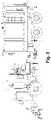
- FIG. 3 is a side view illustrating the system of FIG. 1 secured to a water blasting truck;
- FIG. 4 is a side view illustrating the system of FIG. 1 secured to a rumble strip grinding truck;
- FIG. 5 is a side view illustrating the system of FIG. 1 secured to a road marking truck.
- FIG. 6 is a schematic view illustrating an alternative embodiment of the low speed control system.
- a control system 10 for maintaining low speeds in a work vehicle 22 is illustrated.
- a work vehicle refers to a vehicle that is used to do work as it moves, utilizing equipment secured to the vehicle to do the work, and particularly at low speeds or speeds at or less than 10 miles per hour.
- Low speeds are difficult to maintain with a work vehicle that is typically heavy and may include a manual or automatic primary transmission 46 .
- Hills and undulating terrain create problems, as the work vehicle is traveling up and down hills or around corners; making it difficult to maintain a desired and consistent working speed.
- FIG. 3 illustrates a water blasting truck 52 for removing markings from a roadway;
- FIG. 3 illustrates a water blasting truck 52 for removing markings from a roadway
- FIG. 4 illustrates a grinder truck 54 for making rumble strips, reflector troughs and the like; and FIG. 5 illustrates a paint truck 56 for applying roadway markings. While these trucks are illustrative of low speed work trucks, the present construction is not limited to these particular trucks, and the technology can be utilized on any low speed work type vehicle for maintaining consistent low speeds.
- the work vehicle typically includes a frame 42 , an engine 44 connected to a driveline 45 for propelling said work vehicle, said driveline including a primary transmission 46 , at least one driveshaft 40 and a drive axle 30 .
- the driveline 45 may further include a secondary transmission 48 for driving auxiliary equipment, such as pumps and the like.
- a brake system 58 for slowing or stopping the work vehicle may be hydraulic or air powered and may include at least one spring brake 82 that is also air operated, as is known in the art.
- the low speed control system 10 includes a low speed control module 14 for establishing and monitoring a user set low speed for the vehicle 22 to maintain.
- the low speed control module 14 is in electrical communication with a display monitor 18 , a brake module 60 , and the vehicle's on-board computer 34 .
- the low speed control module 14 may include memory, processors and the like, which allow the low speed control system 10 to record and recall speeds, average work speeds, and skip speeds which allow the vehicle to speed up and slow down at predetermined intervals and the like.
- the display monitor 18 can be utilized to establish the low speed desired for vehicle travel, and may provide increased working speeds by speeding the vehicle between, for example, intermittent road stripes.
- the brake module 60 includes an Eddy current brake assembly 16 .
- the Eddy current brake assembly 16 includes a brake rotor 62 and an Eddy brake caliper 64 .
- the brake rotor 62 is constructed and arranged to rotate with a portion of the vehicle when the vehicle moves, for example a driveshaft 40 , axle 50 or the like.
- the Eddy brake rotor 62 is constructed from a conductive metal having an electromagnet 66 positioned in the caliper 64 so that a portion of the electromagnet 66 is positioned on each side of the rotor, so that the magnetic field passes through the rotor 62 .
- Power supplied to the electromagnet 66 regulates the braking force, e.g. more electrical power provides more drag on the vehicle. In this manner, the braking or drag force can be regulated to control the speed of the vehicle as it traverses hills and curves and other terrain.
- the low speed control module 14 is in electrical communication with a throttle control 20 for the engine of the vehicle 22 . This communication may be to a solenoid or motor to move the throttle.
- the low speed control module 14 is in electrical communication with the vehicle's on-board computer 34 , which provides access to the throttle control through the on-board computer 34 .
- the speed of the vehicle may be monitored in place of, or in addition to, the encoder 12 , and the throttle of the vehicle engine may be utilized to speed up the vehicle in an uphill or other maneuver that requires additional speed to achieve the set speed 36 .
- one air brake 58 as part of the factory air brake system 70 , includes an air control valve 72 positioned along an air-line 74 extending to an air brake 58 , said air control valve 72 in electrical communication with said low speed control module 14 so that said air control valve 72 regulates an amount of pressurized air maintained within the air brake 58 to control drag on that particular air brake.
- the low speed control system includes a temperature sensor 78 positioned to monitor an operating temperature of the air brake 58 . The temperature sensor 78 is in electrical communication with the low speed control module 14 .
- the low speed control system 10 includes a plurality of temperature sensors 78 , each temperature sensor positioned to monitor an operating temperature of a different air brake 58 and in electrical communication with the low speed control module 14 . In this manner, the low speed control system 10 can monitor the temperature of each air brake 58 and switch from one air brake 58 to a different brake 58 as the temperature of the brake increases, or simply to equalize the wear on the brake shoes or pads 80 .
- an air control valve 72 is positioned along a respective air-line 74 extending to a respective air brake 58 , each air control valve 72 in electrical communication with the low speed control module 14 .
- an algorithm may be utilized to determine which brake should be utilized next to maintain the desired brake temperature and wear characteristics desired.
- the air pressure sensor 76 should be suitable for measuring air pressure within the respective air-line 74 , and be in electrical communication with the low speed control module 14 .
- the present system is suitable for use with all air brakes, including spring brakes 82 , drum brakes 83 and disc brakes 84 , and a system may include any number of any of these types of brakes without departing from the scope of the invention.
- air pressure is used to control spring pressure against brake operation, so that spring pressure applied to the spring is limited to cause drag on the work vehicle.
Landscapes
- Engineering & Computer Science (AREA)
- Mechanical Engineering (AREA)
- Transportation (AREA)
- Chemical & Material Sciences (AREA)
- Combustion & Propulsion (AREA)
- Automation & Control Theory (AREA)
- General Engineering & Computer Science (AREA)
- Power Engineering (AREA)
- Architecture (AREA)
- Civil Engineering (AREA)
- Structural Engineering (AREA)
- Regulating Braking Force (AREA)
Abstract
Description
Claims (9)
Priority Applications (1)
| Application Number | Priority Date | Filing Date | Title |
|---|---|---|---|
| US16/156,469 US11479249B2 (en) | 2018-10-10 | 2018-10-10 | Speed control system for road equipment |
Applications Claiming Priority (1)
| Application Number | Priority Date | Filing Date | Title |
|---|---|---|---|
| US16/156,469 US11479249B2 (en) | 2018-10-10 | 2018-10-10 | Speed control system for road equipment |
Publications (2)
| Publication Number | Publication Date |
|---|---|
| US20200114918A1 US20200114918A1 (en) | 2020-04-16 |
| US11479249B2 true US11479249B2 (en) | 2022-10-25 |
Family
ID=70162233
Family Applications (1)
| Application Number | Title | Priority Date | Filing Date |
|---|---|---|---|
| US16/156,469 Active 2040-09-07 US11479249B2 (en) | 2018-10-10 | 2018-10-10 | Speed control system for road equipment |
Country Status (1)
| Country | Link |
|---|---|
| US (1) | US11479249B2 (en) |
Families Citing this family (1)
| Publication number | Priority date | Publication date | Assignee | Title |
|---|---|---|---|---|
| US20240190585A1 (en) * | 2022-12-13 | 2024-06-13 | Waterblasting, Llc | Gps directed ultra-high pressure runway cleaner |
Citations (11)
| Publication number | Priority date | Publication date | Assignee | Title |
|---|---|---|---|---|
| US5217282A (en) * | 1991-02-06 | 1993-06-08 | Messier-Bugatti | Device for controlled braking of a wheel train with temperature comparison |
| US6048040A (en) * | 1995-05-13 | 2000-04-11 | Haldex Brake Products Limited | Vehicle braking system with drive wheel slip control |
| US20140076641A1 (en) * | 2012-05-21 | 2014-03-20 | Krassimire Mihaylov Penev | Self rechargeable synergy drive for a motor vehicle |
| US20140318903A1 (en) * | 2012-08-17 | 2014-10-30 | Edwin Bernard Simpson | Safety valve for trailer |
| US20150283866A1 (en) * | 2012-11-30 | 2015-10-08 | Wabco Gmbh | Method and Device for tyre Pressure Regulation and for Automatic Repair |
| US20150329116A1 (en) * | 2012-12-20 | 2015-11-19 | CNH Industrial America, LLC | System And Method for Controlling the Operation of a Work Vehicle Having a Power Shift Transmission and a Proportional Parking Brake |
| US20180222477A1 (en) * | 2017-02-03 | 2018-08-09 | Ford Global Technologies, Llc | Speed controller for a vehicle |
| US20190135249A1 (en) * | 2017-11-09 | 2019-05-09 | Ford Global Technologies, Llc | Electric parking brake with regenerative braking control system and method |
| US20190256066A1 (en) * | 2016-11-14 | 2019-08-22 | Hino Motors, Ltd. | Brake system |
| US20200317060A1 (en) * | 2016-05-25 | 2020-10-08 | Jaguar Land Rover Limited | Apparatus, system and method for braking |
| US20210221341A1 (en) * | 2018-06-01 | 2021-07-22 | Freni Brembo S.P.A. | Method for controlling a braking system of a vehicle and related system |
-
2018
- 2018-10-10 US US16/156,469 patent/US11479249B2/en active Active
Patent Citations (11)
| Publication number | Priority date | Publication date | Assignee | Title |
|---|---|---|---|---|
| US5217282A (en) * | 1991-02-06 | 1993-06-08 | Messier-Bugatti | Device for controlled braking of a wheel train with temperature comparison |
| US6048040A (en) * | 1995-05-13 | 2000-04-11 | Haldex Brake Products Limited | Vehicle braking system with drive wheel slip control |
| US20140076641A1 (en) * | 2012-05-21 | 2014-03-20 | Krassimire Mihaylov Penev | Self rechargeable synergy drive for a motor vehicle |
| US20140318903A1 (en) * | 2012-08-17 | 2014-10-30 | Edwin Bernard Simpson | Safety valve for trailer |
| US20150283866A1 (en) * | 2012-11-30 | 2015-10-08 | Wabco Gmbh | Method and Device for tyre Pressure Regulation and for Automatic Repair |
| US20150329116A1 (en) * | 2012-12-20 | 2015-11-19 | CNH Industrial America, LLC | System And Method for Controlling the Operation of a Work Vehicle Having a Power Shift Transmission and a Proportional Parking Brake |
| US20200317060A1 (en) * | 2016-05-25 | 2020-10-08 | Jaguar Land Rover Limited | Apparatus, system and method for braking |
| US20190256066A1 (en) * | 2016-11-14 | 2019-08-22 | Hino Motors, Ltd. | Brake system |
| US20180222477A1 (en) * | 2017-02-03 | 2018-08-09 | Ford Global Technologies, Llc | Speed controller for a vehicle |
| US20190135249A1 (en) * | 2017-11-09 | 2019-05-09 | Ford Global Technologies, Llc | Electric parking brake with regenerative braking control system and method |
| US20210221341A1 (en) * | 2018-06-01 | 2021-07-22 | Freni Brembo S.P.A. | Method for controlling a braking system of a vehicle and related system |
Also Published As
| Publication number | Publication date |
|---|---|
| US20200114918A1 (en) | 2020-04-16 |
Similar Documents
| Publication | Publication Date | Title |
|---|---|---|
| EP1186711B1 (en) | Method and apparatus for applying a night visible traffic stripe to a road | |
| US5114268A (en) | Apparatus for applying a traffic stripe to a road | |
| EP1159489B1 (en) | Audible night-visible traffic stripe for a road and method and apparatus for making the same | |
| JP2023524992A (en) | Predictive vehicle motion assistance | |
| US11479249B2 (en) | Speed control system for road equipment | |
| US5059060A (en) | Traffic control system | |
| US20180251946A1 (en) | Metallic Striping on Roads for Vehicle Guidance | |
| US20210046499A1 (en) | Fluid application for autonomous haul trucks | |
| WO2018094206A2 (en) | Self-guided road marking system | |
| US20190234403A1 (en) | Pump for melted thermoplastic materials | |
| US20220316158A1 (en) | Directional warning system and method | |
| KR200416774Y1 (en) | Synthetic resin boundary stone with light emitting means interlocked with traffic lights in pedestrian crossing | |
| CN108252190A (en) | A kind of milling mechanism walking anti-slip hydraulic control system | |
| KR100939536B1 (en) | Lane indicator | |
| CN110983937A (en) | Intelligent infrared induction marking-off integrated machine | |
| KR20190128938A (en) | Intaglio road surface formation system | |
| US20210403030A1 (en) | Laser based computer controlled topographic profiler | |
| CA2706766A1 (en) | Strategically shifting traffic lines to reduce or eliminate rutting in roads | |
| CN210284197U (en) | Track-following navigation safe driving system for snow-covered road of unmanned automobile | |
| CN209759991U (en) | Concrete is line printer for paint finishing | |
| US20070098493A1 (en) | Extended life road system and method | |
| US9108459B2 (en) | System and method for advertising | |
| RU2159828C2 (en) | Pavement usage method | |
| CA2303573A1 (en) | Reflective rubber marker | |
| Alionte et al. | Snow Mobile Robot-SnowBie |
Legal Events
| Date | Code | Title | Description |
|---|---|---|---|
| FEPP | Fee payment procedure |
Free format text: ENTITY STATUS SET TO UNDISCOUNTED (ORIGINAL EVENT CODE: BIG.); ENTITY STATUS OF PATENT OWNER: SMALL ENTITY |
|
| AS | Assignment |
Owner name: WATERBLASTING, LLC, FLORIDA Free format text: ASSIGNMENT OF ASSIGNORS INTEREST;ASSIGNOR:CROCKER, JAMES P.;REEL/FRAME:048212/0721 Effective date: 20190131 |
|
| FEPP | Fee payment procedure |
Free format text: ENTITY STATUS SET TO SMALL (ORIGINAL EVENT CODE: SMAL); ENTITY STATUS OF PATENT OWNER: SMALL ENTITY |
|
| STPP | Information on status: patent application and granting procedure in general |
Free format text: NON FINAL ACTION MAILED |
|
| STPP | Information on status: patent application and granting procedure in general |
Free format text: RESPONSE TO NON-FINAL OFFICE ACTION ENTERED AND FORWARDED TO EXAMINER |
|
| STPP | Information on status: patent application and granting procedure in general |
Free format text: FINAL REJECTION MAILED |
|
| STPP | Information on status: patent application and granting procedure in general |
Free format text: DOCKETED NEW CASE - READY FOR EXAMINATION |
|
| STPP | Information on status: patent application and granting procedure in general |
Free format text: NON FINAL ACTION MAILED |
|
| STPP | Information on status: patent application and granting procedure in general |
Free format text: RESPONSE TO NON-FINAL OFFICE ACTION ENTERED AND FORWARDED TO EXAMINER |
|
| STPP | Information on status: patent application and granting procedure in general |
Free format text: NOTICE OF ALLOWANCE MAILED -- APPLICATION RECEIVED IN OFFICE OF PUBLICATIONS |
|
| STPP | Information on status: patent application and granting procedure in general |
Free format text: PUBLICATIONS -- ISSUE FEE PAYMENT VERIFIED |
|
| STCF | Information on status: patent grant |
Free format text: PATENTED CASE |
|
| AS | Assignment |
Owner name: FSC HIGHLANDER LLC, ILLINOIS Free format text: ASSIGNMENT OF ASSIGNORS INTEREST;ASSIGNOR:WATERBLASTING, LLC;REEL/FRAME:070238/0112 Effective date: 20250212 |
|
| AS | Assignment |
Owner name: FEDERAL SIGNAL CORPORATION, ILLINOIS Free format text: ASSIGNMENT OF ASSIGNORS INTEREST;ASSIGNOR:FSC HIGHLANDER LLC;REEL/FRAME:070785/0723 Effective date: 20250407 Owner name: FSC HIGHLANDER LLC, ILLINOIS Free format text: ASSIGNMENT OF ASSIGNORS INTEREST;ASSIGNOR:WATERBLASTING LLC;REEL/FRAME:070784/0419 Effective date: 20250325 |
|
| FEPP | Fee payment procedure |
Free format text: ENTITY STATUS SET TO UNDISCOUNTED (ORIGINAL EVENT CODE: BIG.); ENTITY STATUS OF PATENT OWNER: LARGE ENTITY |