EP3801937B1 - Reinigungsanordnung für eine beschichtungsvorrichtung - Google Patents
Reinigungsanordnung für eine beschichtungsvorrichtung Download PDFInfo
- Publication number
- EP3801937B1 EP3801937B1 EP19810223.8A EP19810223A EP3801937B1 EP 3801937 B1 EP3801937 B1 EP 3801937B1 EP 19810223 A EP19810223 A EP 19810223A EP 3801937 B1 EP3801937 B1 EP 3801937B1
- Authority
- EP
- European Patent Office
- Prior art keywords
- base
- arrangement
- scraping
- wall
- coating apparatus
- Prior art date
- Legal status (The legal status is an assumption and is not a legal conclusion. Google has not performed a legal analysis and makes no representation as to the accuracy of the status listed.)
- Active
Links
Images


Classifications
-
- B—PERFORMING OPERATIONS; TRANSPORTING
- B08—CLEANING
- B08B—CLEANING IN GENERAL; PREVENTION OF FOULING IN GENERAL
- B08B1/00—Cleaning by methods involving the use of tools
- B08B1/10—Cleaning by methods involving the use of tools characterised by the type of cleaning tool
- B08B1/16—Rigid blades, e.g. scrapers; Flexible blades, e.g. wipers
- B08B1/165—Scrapers
-
- B—PERFORMING OPERATIONS; TRANSPORTING
- B05—SPRAYING OR ATOMISING IN GENERAL; APPLYING FLUENT MATERIALS TO SURFACES, IN GENERAL
- B05B—SPRAYING APPARATUS; ATOMISING APPARATUS; NOZZLES
- B05B13/00—Machines or plants for applying liquids or other fluent materials to surfaces of objects or other work by spraying, not covered by groups B05B1/00 - B05B11/00
- B05B13/02—Means for supporting work; Arrangement or mounting of spray heads; Adaptation or arrangement of means for feeding work
- B05B13/0221—Means for supporting work; Arrangement or mounting of spray heads; Adaptation or arrangement of means for feeding work characterised by the means for moving or conveying the objects or other work, e.g. conveyor belts
- B05B13/025—Means for supporting work; Arrangement or mounting of spray heads; Adaptation or arrangement of means for feeding work characterised by the means for moving or conveying the objects or other work, e.g. conveyor belts the objects or work being present in bulk
- B05B13/0257—Means for supporting work; Arrangement or mounting of spray heads; Adaptation or arrangement of means for feeding work characterised by the means for moving or conveying the objects or other work, e.g. conveyor belts the objects or work being present in bulk in a moving container, e.g. a rotatable foraminous drum
-
- B—PERFORMING OPERATIONS; TRANSPORTING
- B05—SPRAYING OR ATOMISING IN GENERAL; APPLYING FLUENT MATERIALS TO SURFACES, IN GENERAL
- B05C—APPARATUS FOR APPLYING FLUENT MATERIALS TO SURFACES, IN GENERAL
- B05C3/00—Apparatus in which the work is brought into contact with a bulk quantity of liquid or other fluent material
- B05C3/02—Apparatus in which the work is brought into contact with a bulk quantity of liquid or other fluent material the work being immersed in the liquid or other fluent material
- B05C3/04—Apparatus in which the work is brought into contact with a bulk quantity of liquid or other fluent material the work being immersed in the liquid or other fluent material with special provision for agitating the work or the liquid or other fluent material
- B05C3/08—Apparatus in which the work is brought into contact with a bulk quantity of liquid or other fluent material the work being immersed in the liquid or other fluent material with special provision for agitating the work or the liquid or other fluent material the work and the liquid or other fluent material being agitated together in a container, e.g. tumbled
-
- B—PERFORMING OPERATIONS; TRANSPORTING
- B08—CLEANING
- B08B—CLEANING IN GENERAL; PREVENTION OF FOULING IN GENERAL
- B08B1/00—Cleaning by methods involving the use of tools
- B08B1/30—Cleaning by methods involving the use of tools by movement of cleaning members over a surface
- B08B1/32—Cleaning by methods involving the use of tools by movement of cleaning members over a surface using rotary cleaning members
- B08B1/34—Cleaning by methods involving the use of tools by movement of cleaning members over a surface using rotary cleaning members rotating about an axis parallel to the surface
-
- B—PERFORMING OPERATIONS; TRANSPORTING
- B08—CLEANING
- B08B—CLEANING IN GENERAL; PREVENTION OF FOULING IN GENERAL
- B08B9/00—Cleaning hollow articles by methods or apparatus specially adapted thereto
- B08B9/08—Cleaning containers, e.g. tanks
- B08B9/0804—Cleaning containers having tubular shape, e.g. casks, barrels, drums
- B08B9/0808—Cleaning containers having tubular shape, e.g. casks, barrels, drums by methods involving the use of tools, e.g. by brushes, scrapers
-
- B—PERFORMING OPERATIONS; TRANSPORTING
- B08—CLEANING
- B08B—CLEANING IN GENERAL; PREVENTION OF FOULING IN GENERAL
- B08B9/00—Cleaning hollow articles by methods or apparatus specially adapted thereto
- B08B9/08—Cleaning containers, e.g. tanks
- B08B9/087—Cleaning containers, e.g. tanks by methods involving the use of tools, e.g. brushes, scrapers
-
- A—HUMAN NECESSITIES
- A01—AGRICULTURE; FORESTRY; ANIMAL HUSBANDRY; HUNTING; TRAPPING; FISHING
- A01C—PLANTING; SOWING; FERTILISING
- A01C1/00—Apparatus, or methods of use thereof, for testing or treating seed, roots, or the like, prior to sowing or planting
- A01C1/06—Coating or dressing seed
-
- B—PERFORMING OPERATIONS; TRANSPORTING
- B08—CLEANING
- B08B—CLEANING IN GENERAL; PREVENTION OF FOULING IN GENERAL
- B08B2220/00—Type of materials or objects being removed
- B08B2220/01—Adhesive materials
Definitions
- the present invention relates to a cleaning coating apparatus.
- Coating apparatus such as rotary batch coaters, are used to coat loose materials such as seeds and clay granules.
- seeds are routinely coated with one or more substances (such as pesticides, insecticides, coloring and finishing powders) to improve their performance (e.g. to improve germination rates, growth rates and/or resistance to pests).
- the coating material includes one or more glues and one or more active ingredients. Coating is sometimes referred to as 'pelleting' or 'encrusting'.
- Coating apparatuses with a base having an outer conical wall are, e.g., known from EP 2 992 766 B1 , GB 2 070 450 A , US 2 863 904 A , WO 00/16887 A1 , EP 0761 296 A1 and DE 44 11 058 A1 .
- the coating material adheres to (and thus forms buildup on) the portions of the coating apparatus that come into contact with the loose material.
- DE 101 24 477 C1 discloses a coating apparatus having a base for carrying loose material, wherein the base is rotatable to coat the loose material.
- the coating apparatus further has a cleaning arrangement which includes a base-scraping arrangement.
- the base-scraping arrangement is mounted by a mounting arrangement to be reversibly lowered, from a coating position, to a scraping position at which the base-scraping arrangement is positioned to scrape buildup from the base.
- the base-scraping arrangement is shaped for buildup scraped from the base to be driven, by rotation of the base, outwardly along the base-scraping arrangement to clear the base of the buildup scraped from the base.
- Embodiments of the present invention seek to provide improvements in and for coating, or at least to provide useful alternatives for those concerned with coating.
- the mounting arrangement may include an actuator to move, e.g. downwardly drive, the base-scraping arrangement.
- the base-scraping arrangement is shaped for buildup scraped from the base to be driven, by rotation of the base, outwardly along the base-scraping arrangement to clear the base of the buildup scraped from the base.
- the base includes a conical outer wall for surrounding the loose material.
- the base-scraping arrangement includes a portion for scraping the conical outer wall and inclined rearwardly relative to the rotation of the base.
- the base-scraping arrangement includes one or more portions for contacting the buildup and mounted adjustably to enable a clearance to the base to be adjusted.
- the base includes a central raised portion and the base-scraping arrangement is shaped to scrape the central raised portion.
- the coating apparatus may include a wall arrangement surrounding, and together with the base defining, a space for holding the loose material.
- the cleaning apparatus may include a wall-scraping arrangement configured to rotate within the space to scrape buildup from the wall arrangement.
- the cleaning arrangement includes a control arrangement configured to coordinate the base-scraping arrangement and the wall-scraping arrangement.
- the wall arrangement may include an outlet openable to enable buildup to escape the space and closeable to retain the loose material.
- the coating apparatus may include a control arrangement configured to coordinate the outlet and the cleaning apparatus.
- the coating apparatus may include a diverter downstream of the outlet reconfigurable to divert material from the outlet to a selected one of at least two destinations.
- a or the control arrangement may be configured to coordinate the diverter and the cleaning apparatus.
- Another aspect of the invention provides a method of coating loose material including the features of claim 14.
- the method includes rotating a base to agitate the loose material and the coating material.
- the operating the wall-scraping arrangement is counter-rotating the wall-scraping arrangement relative the base.
- a coating apparatus for coating loose material, including
- the at least one of the base and the wall arrangement may include supporting structure.
- the replaceable wear arrangement may have an operative portion and be flexible relative to the supporting structure.
- the supporting structure may support the replaceable wear element to keep the operative portion concentric to the axis.
- the replaceable wear arrangement includes radial bores, e.g. threaded bores, by which the replaceable wear arrangement is attached to the supporting structure.
- the replaceable wear arrangement may be a ring, e.g. a ring with a substantially rectangular profile.
- an or the operative portion of replaceable wear arrangement is softer than a portion of the other of the base and the wall arrangement against which the operative portion wears.
- the wall arrangement includes the replaceable wear arrangement.
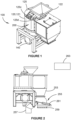
- the coating apparatus 100 is a rotary batch coater for coating seed.
- the apparatus includes a coating chamber 120 including a wall arrangement 121, a base 123 and a lid 125.
- the wall arrangement 121 surrounds a space, atop the base 123, for coating the seed.
- the space is closed by the lid 125.
- the lid 125 is equipped with a funnel 122 for receiving seed into the seed coating chamber. Other forms of inlet are possible.
- the lid 125 further includes a coating material inlet arrangement 125c, 125d and a dust extraction port 125e ( Figure 3A ).
- the coating material inlet arrangement 125c, 125d includes a port 125c, surrounded by a bolting flange, and a simple hole 125d surrounded by bolt holes.
- the inlets 125c, 125d will typically be plumbed to suitable powder conveying conduits associated with powder dispensing apparatus, e.g. with dispensers incorporating augers responsive to load cells to deliver a defined amount of powder.
- the port 122 would be connected to a suitable duct via which dust is extracted.
- the dust-carrying air extracted from the chamber 120 is routed through a suitable filtering arrangement.
- seed and coating material are supplied to the chamber 120 and the base is rotated by an underlying motor 140 while the wall arrangement is stationary.
- the movement and relative movement stirs and agitates the materials to coat the seed in the coating material.
- the motor 140 may be configured to rotate the rotating base at about 230 RPM.
- the speed of the rotating base is adjustable, e.g. the motor 140 might be driven by a variable speed drive.
- the lid 125 defines a lower portion 125a and an upper portion 125b each of which, in this example, takes the form of a horizontal portion of sheet material.
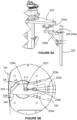
- the cleaning assembly 200 includes a rotatable set of parts 231 and a non-rotating set of parts 233.
- the rotating set of parts 231 includes sprocket 221 and drive hub 222 of the hub 220.
- the drive hub 222 is upright and tubular, and includes an outwardly projecting radial flange about its lower end.
- the sprocket is connected to a top of the drive hub 222 via a connecting ring 290 and arrangements of keys and keyways between the components.
- the sprocket forms part of a chain-drive transmission by which the rotating set 231 is driven by a motor (not shown).
- the drive hub 222 is mounted to rotate with a body mount hub 224 of the hub 220.
- the hub 224 is upright and tubular, and includes an outwardly projecting radial flange about its lower end.
- the flange of the hub 224 is a bolting flange by which the hub 224 is fixed to the lower portion 125a.
- the non-rotating set 233 is suspended from the upper portion 125b.
- a suspending member 226 is fastened to the upper portion 125b and extends downwardly through the hub 222.
- Glacial bearings 227 are fitted between the hub 222 and the member 226 whereby the hub 222 laterally supports the member 226.
- the base 125 includes a drive hub 126 and an outer body 128 carried by the drive hub 126.
- the drive hub 126 upwardly presents a downwardly-divergent conical exterior.
- the outer body defines a horizontal floor 128a and an upwardly divergent conical exterior 128b.
- the base 123 is carried by a tubular drive shaft 269 and an arrangement of thrust bearings.
- An atomising arrangement 271 is arranged to atomise fluid received via the member 226 and includes a rotor 273 at the top of a drive shaft 275 carried concentrically within the drive shaft 269 by bearings.
- the rotor 273 takes the form of a saucer-like disc and is positioned to sit above the loose material and rotate at speed, e.g. at 1,400 RPM, to atomise, and disperse over the loose material, the incoming liquid.
- the member 226 may internally carry several flexible liquid-introducing lines for supplying separate liquids.
- the non-rotating portion 233 includes a base-scraping arrangement 127 ( Figure 4B ).
- the arrangement 127 includes a base-scraping member 129 and a mounting arrangement 131.
- the mounting arrangement 131 includes the suspending member 226 and an actuated pivotal connection 228 by which the base-scraping member is mounted to be pivotally lowered from coating position to a base-scraping position.
- the inner tube of the member 226 has a wall thickness within which conduits for carrying the lines 228e, 228f are formed.
- the lower ends of the lines 228e, 228f emerge laterally from the member 226 and are connected to the actuator 228a via flexible lines (not shown).
- the tops of the lines 228e, 228f project upwardly beyond the upper portion 125b for connection to a pressure source.
- the brackets 228b, 228c are vertically spaced from each other along the member 226.
- the lower bracket defines a yoke for receiving a vertical planar web 243b of the base-scraping member 129 and via which the member 129 is pivotally mounted. In this case the member 129 is mounted to pivot about a horizontal pivot axis PA.
- a body of the actuator 228a is pivotally connected to the upper bracket 228b.
- a rod end of the actuator 228a is pivotally connected to the base-scraping member 129 via the the spacer 228d.
- the base-scraping member 129 is a five part construction including:
- the blade-carrying piece 243d is a planar portion shaped to curve about the lower edges of the portions 243b, 243c.
- the blade 244 is another planar piece and has a shape complementary to portion 243d.
- the blade 244 is mounted to the portion 243d in a manner akin to the mounting between components 245, 246 whereby a clearance CF ( Figure 7 ) to the floor can be adjusted.
- the actuator 228 is also adjustable.
- the rod of the ram 228 terminates in a rose joint co-operable with the spacer 228d and includes a threaded adjustment by which the effective length of the rod is adjustable.
- the rotating parts 231 form part of a wall-scraping arrangement 232 and includes an elongate drive arm 223. A mid portion of the arm 223 is directly bolted to the hub 222. One end of the arm 223 carries a wall-scraping blade 229 whilst the other end carries a paddle 237. As best shown in Figures 5a and 5b the blade 229 is an upright member adjustably connected to the arm 223 via a bracket 239.
- Bracket 239 includes a body 239a shaped to sit flat against a planar underside of the arm 223. An end of the body 239 is bolted to the blade 229.
- the bracket 239 further includes a diagonal brace 239b extending downwardly from the body 239a at an oblique angle to provide further support to the blade 229.
- the body 239a has a slotted bolt hole 239c through which a bolt engages a threaded bore of the arm 223 to mount the bracket.
- An end of the body 239a spaced from the blade 229 is surrounded by a trio of lugs 223a.
- Each of the lugs 223a defines a respective internally threaded horizontal bore through which a respective adjustment bolt is passed to act on the body 239a.
- the blade 239 is thus screw adjustable to enable the clearance CW and the clearance angle CA to be varied.
- Other modes of screw adjustment, and indeed other modes of adjustment more generally, are possible. In this example a clearance of not more than 12 mm, a clearance angle in the vicinity of 8 degrees and a lip angle in the vicinity of 40 degrees are preferred.
- the rotating assembly 231 may be held stationary whilst coating is in progress.
- the stationary blade 229 and paddle 237 can agitate the loose material upwardly driven against those components by the rotation of the base 125.
- the rotating arrangement may be rotated whilst coating is in progress, e.g. the rotating set of parts 231 might be rotated in a direction opposite to a direction of rotation of the base 125. This can lead to more efficient use of the coating materials in that the coating material can be scraped from a wall before it sets and subsequently adhere to the loose material.
- the rotating set of parts also provides additional agitation to the loose material whereby 'dead spots' of untreated seeds are less likely - indeed, a bladeless variant of the set of parts 231 would be useful.
- the drive and transmission are configured to turn the set of parts 231 at about 5 RPM.
- the cylindrical interior of the wall arrangement 121 is partly defined by a door 241 which serves to close an outlet 249 during the coating operation.
- Door 241 is suspended from a pivotal mounting (defining a horizontal pivot axis) and driven by an actuator 251 to pivot outwardly to open outlet 249 to enable material to pass from the chamber 120 into receiving space 253.
- the receiving space 253 is downwardly open and shaped to funnel the material down towards a diverter 255 ( Figure 1A).
- the diverter 255 is operable to selectively direct the material to a selected one of a first outlet 257 and a second outlet 259.
- Other mechanisms for selectively directing are possible.
- the diverter takes the form of a flap driven by an actuator 261 and the actuators 251, 261 are pneumatic rams.
- control arrangement 263 may close the door 241 and deactivate the motor 140 to await further user and material input.
- the control arrangement 263 is configured to switch the diverter 255 substantially simultaneously with the lowering of the base-scraping arrangement 127 whereby the waste material is directed through the outlet 257.
- An interior of the cylindrical wall of the stationary base 267 is stepped to define an annular ledge 267a and an inwardly directed cylindrical 267b.
- An exterior of the base 123, or more specifically the body 128 in this case, has a complementary step defining an annular ledge 128a and an outwardly directed cylindrical surface 128b.
- the arrangement 265 is relatively flexible, it is supported by the stationary base 267 to hold its operative portion 265b concentric to the rotation axis RA whereby a small peripheral clearance PC (between the surfaces 128b, 265b) become practical.
- a nominal clearance in the vicinity of 0.8 mm is preferred albeit that with typical circularity tolerances, and other practical variations, some rubbing occurs. This narrow gap impedes the loss of seed from the chamber 120.
- the arrangement 265 might take other forms, e.g. instead of a single integrally formed ring, multiple arcuate segments might be placed end to end.
- the stationary base 267 carries the arrangement 265
- the rotor 123 may carry the arrangement 265.
- each of the rotor and the wall arrangement might carry a respective replaceable element.
Landscapes
- Engineering & Computer Science (AREA)
- Mechanical Engineering (AREA)
- Coating Apparatus (AREA)
- Pretreatment Of Seeds And Plants (AREA)
Claims (14)
- Beschichtungsvorrichtung (100) mit einer Basis (123) zum Tragen von losem Material;wobei die Basis (123) rotierbar ist zum Beschichten des losen Materials;wobei die Beschichtungsvorrichtung (100) eine Reinigungsanordnung aufweist;wobei die Reinigungsanordnung Folgendes umfasst:eine Basisabstreifanordnung (127); undeine Befestigungsanordnung (131), über die die Basisabstreifanordnung (127) befestigt ist, um reversibel aus einer Beschichtungsposition in eine Abstreifposition, an der die Basisabstreifanordnung (127) positioniert ist, um Ansammlungen von der Basis (123) abzustreifen, abgesenkt zu werden,wobei die Basisabstreifanordnung (127) so geformt ist, dass Ansammlungen, die von der Basis (123) abgestreift werden, durch Rotation der Basis (123) nach auswärts entlang der Basisabstreifanordnung (127) getrieben werden, um die Basis (123) von den von der Basis (123) abgestreiften Ansammlungen zu befreien, undwobei die Basisabstreifanordnung (127) ein nicht rotierender Teil (233) ist, umfassend ein Basisabstreifelement (129) und die Befestigungsanordnung (131),dadurch gekennzeichnet, dassdie Basis (123) eine konische äußere Wand zum Umgeben des losen Materials umfasst; und wobei die Basisabstreifanordnung (127) einen Teil zum Abstreifen der konischen äußeren Wand umfasst und relativ zur Rotation der Basis (123) nach hinten geneigt ist,und dadurch, dass die Befestigungsanordnung (131) ein Aufhängeelement (226) und eine betätigte Schwenkverbindung (228) umfasst, über die das Basisabstreifelement (129) befestigt ist, um schwenkend von einer Beschichtungsposition in eine Basisabstreifposition abgesenkt zu werden.
- Beschichtungsvorrichtung (100) nach Anspruch 1, wobei die Befestigungsanordnung (131) einen Aktuator (228a) zum Bewegen der Basisabstreifanordnung (127) umfasst.
- Beschichtungsvorrichtung (100) nach Anspruch 2, wobei der Aktuator (228a) dazu ausgelegt ist, die Basisabstreifanordnung (127) nach unten anzutreiben.
- Beschichtungsvorrichtung (100) nach einem der Ansprüche 1 bis 3, wobei die Basisabstreifanordnung (127) einen oder mehrere Teile zum Inkontaktkommen mit den Ansammlungen umfasst und einstellbar befestigt ist, um zu ermöglichen, einen Abstand zur Basis (123) einzustellen.
- Beschichtungsvorrichtung (100) nach Anspruch 4, wobei die Basis (123) einen mittleren erhöhten Teil umfasst und die Basisabstreifanordnung (127) geformt ist, um den mittleren erhöhten Teil abzustreifen.
- Beschichtungsvorrichtung (100) nach Anspruch 4 oder Anspruch 5, wobei die Beschichtungsvorrichtung (100) eine Wandanordnung (121), die einen Raum zum Halten des losen Materials umgibt und, zusammen mit der Basis (123), definiert, und eine Wandabstreifanordnung (232), die ausgelegt ist zum Rotieren innerhalb des Raumes, um Ansammlungen von der Wandanordnung (121) abzustreifen, umfasst.
- Beschichtungsanordnung (100) nach Anspruch 6, umfassend eine Steueranordnung (263), ausgelegt zum Koordinieren der Basisabstreifanordnung (127) und der Wandabstreifanordnung (232).
- Beschichtungsvorrichtung (100) nach Anspruch 6 oder 7, wobei die Wandabstreifanordnung (232) einen oder mehrere Teile zum Inkontaktkommen mit den Ansammlungen umfasst und einstellbar befestigt ist, um zu ermöglichen, einen Abstand zur Wandanordnung (121) einzustellen.
- Beschichtungsvorrichtung (100) nach Anspruch 1, umfassend eine Wandanordnung (121), die einen Raum zum Halten des losen Materials umgibt und, zusammen mit der Basis (123), definiert; wobei die Wandanordnung (121) einen Auslass (249) umfasst, der öffenbar ist, um zu ermöglichen, dass die Ansammlungen den Raum verlassen können, und schließbar ist, um das lose Material zurückzuhalten.
- Beschichtungsvorrichtung (100) nach Anspruch 9, wobei der Auslass (249) mit der Basisabstreifanordnung (127) ausgerichtet ist, um Ansammlungen von dort aufzunehmen.
- Beschichtungsvorrichtung (100) nach Anspruch 10, umfassend einen Ableiter (255) stromabwärts des Auslasses (249), neu auslegbar, um Material vom Auslass (249) zu einem ausgewählten von mindestens zwei Zielen abzuleiten.
- Beschichtungsvorrichtung (100) nach Anspruch 11, umfassend eine Steueranordnung (263), ausgelegt zum Koordinieren des Ableiters (255) und der Reinigungsvorrichtung.
- Beschichtungsvorrichtung (100) nach Anspruch 6, wobei die Wandabstreifanordnung (127) arbeitet durch gegensinniges Rotieren relativ zur Basis.
- Verfahren zum Beschichten von losem Material, das Folgendes umfasstZuführen des losen Materials und eines Beschichtungsmaterials zu einem Raum innerhalb einer Einrichtung (100) nach Anspruch 6, definiert durch die Wandanordnung (121);Betreiben einer Wandabstreifanordnung (232) zum Abstreifen von Ansammlungen von der Wandanordnung (121), während das lose Material und das Beschichtungsmaterial durch Rotation der Basis (123) aufgerührt werden, um beschichtetes loses Material zu bilden; und dannÖffnen eines Auslasses (249), um dem beschichteten losen Material zu ermöglichen, den Raum zu verlassen; wobei das Betreiben der Wandabstreifanordnung (127) die Wandabstreifanordnung (232) gegensinnig relativ zur Basis (123) rotieren lässt.
Applications Claiming Priority (2)
| Application Number | Priority Date | Filing Date | Title |
|---|---|---|---|
| AU2018901980A AU2018901980A0 (en) | 2018-06-01 | A cleaning arrangement for a coating apparatus | |
| PCT/AU2019/050559 WO2019227171A1 (en) | 2018-06-01 | 2019-05-31 | A cleaning arrangement for a coating apparatus |
Publications (4)
| Publication Number | Publication Date |
|---|---|
| EP3801937A1 EP3801937A1 (de) | 2021-04-14 |
| EP3801937A4 EP3801937A4 (de) | 2022-03-30 |
| EP3801937C0 EP3801937C0 (de) | 2024-07-24 |
| EP3801937B1 true EP3801937B1 (de) | 2024-07-24 |
Family
ID=68696740
Family Applications (1)
| Application Number | Title | Priority Date | Filing Date |
|---|---|---|---|
| EP19810223.8A Active EP3801937B1 (de) | 2018-06-01 | 2019-05-31 | Reinigungsanordnung für eine beschichtungsvorrichtung |
Country Status (5)
| Country | Link |
|---|---|
| US (1) | US12251742B2 (de) |
| EP (1) | EP3801937B1 (de) |
| AU (2) | AU2019277266B2 (de) |
| NZ (1) | NZ771337A (de) |
| WO (1) | WO2019227171A1 (de) |
Families Citing this family (4)
| Publication number | Priority date | Publication date | Assignee | Title |
|---|---|---|---|---|
| NZ771337A (en) | 2018-06-01 | 2025-09-26 | Graintech Innovation Pty Ltd | A cleaning arrangement for a coating apparatus |
| CN113172759B (zh) * | 2021-04-25 | 2022-09-16 | 四川统揽建设集团有限公司 | 一种水泥稳定土拌和系统及拌和方法 |
| CN116689208B (zh) * | 2023-06-26 | 2025-10-10 | 安徽开林新材料股份有限公司 | 一种涂层涂覆装置 |
| CN119898717B (zh) * | 2025-04-02 | 2025-08-01 | 烟台爱陶漳食品有限公司 | 梨膏生产用成品灌装设备 |
Family Cites Families (28)
| Publication number | Priority date | Publication date | Assignee | Title |
|---|---|---|---|---|
| US2863904A (en) | 1955-05-09 | 1958-12-09 | Gulf Oil Corp | Amine salts of di oxo-octyl orthophosphates |
| US3241945A (en) * | 1963-03-19 | 1966-03-22 | Swift & Co | Method and apparatus for producing granulated solids |
| US3316585A (en) * | 1965-06-16 | 1967-05-02 | Sala Maskinfabriks Aktiebolag | Rotary scraping device for nodulizing drums in pelletizing plants |
| US3752057A (en) * | 1971-11-02 | 1973-08-14 | Dover Corp | Portable scraper-type mixer |
| GB1375943A (en) * | 1972-01-18 | 1974-12-04 | Evans T G | Mixing of granular materials |
| US4082057A (en) * | 1975-04-21 | 1978-04-04 | Tenneco Chemicals, Inc. | Apparatus for spraying interior surface of vessels |
| US4212615A (en) * | 1977-09-13 | 1980-07-15 | Bethlehem Steel Corporation | Rotary drum agglomerating apparatus |
| CA1112026A (en) * | 1978-04-27 | 1981-11-10 | John S. Nixon | Rotary pan pelletizers |
| GB2070450B (en) * | 1980-02-28 | 1983-04-07 | Toroidal Mixers Ltd | Mixing machine |
| US4413970A (en) * | 1981-02-27 | 1983-11-08 | Owens-Corning Fiberglas Corporation | Rotary scrapers |
| DE8705281U1 (de) * | 1987-04-09 | 1987-08-06 | Machinefabriek Klieverik B.V., Oldenzaal | Containerwaschmaschine |
| US5106428A (en) * | 1989-04-07 | 1992-04-21 | Automated Cleaning Systems, Inc. | Method for cleaning containers |
| US5488898A (en) | 1993-03-09 | 1996-02-06 | Hough International, Inc. | Spin blender feed coating |
| DE4411058C2 (de) | 1994-03-30 | 1997-04-03 | Niklas Willy Gmbh | Vorrichtung zum Beschichten von körnigem Gut |
| DE19531189C2 (de) * | 1995-08-24 | 1999-03-04 | Vakumix Ruehr Und Homogenisier | Abstreifvorrichtung |
| JP3839531B2 (ja) * | 1996-11-05 | 2006-11-01 | フロイント産業株式会社 | 遠心転動造粒コーティング装置およびこれを用いた粉粒体の造粒方法ならびにコーティング方法 |
| US5820893A (en) * | 1997-01-23 | 1998-10-13 | Westvaco Corporation | Breakaway scraper blade assembly for a pelletizer |
| WO2000018500A1 (de) | 1998-09-24 | 2000-04-06 | Glatt Systemtechnik Dresden Gmbh | Einrichtung zur herstellung eines schüttfähigen produktes und verfahren zur anwendung der einrichtung |
| US20020014200A1 (en) | 2000-04-25 | 2002-02-07 | Stemler Terry L. | Granule coating apparatus and method |
| DE10124477C1 (de) * | 2001-05-19 | 2002-08-01 | Glatt Systemtechnik Dresden | Einrichtung zur Reinigung einer Pelletiereinrichtung |
| JP5324881B2 (ja) * | 2008-10-21 | 2013-10-23 | フロイント産業株式会社 | パンコーティング装置 |
| US8671872B2 (en) * | 2009-02-16 | 2014-03-18 | Thomas Engineering Inc. | Production coater with exchangeable drums |
| US9381550B2 (en) * | 2013-05-06 | 2016-07-05 | Spokane Industires | Self-cleaning tank |
| ES2610307T3 (es) * | 2014-08-13 | 2017-04-26 | Intersnack Group Gmbh & Co. Kg | Procedimiento y dispositivo para recubrir o mezclar productos granulares, más precisamente, maní, con una sustancia |
| US20170036254A1 (en) * | 2015-08-03 | 2017-02-09 | Chemglass Inc. | Rotary scraping tool |
| JP6409789B2 (ja) * | 2016-01-22 | 2018-10-24 | トヨタ自動車株式会社 | 湿潤粉体製造装置および湿潤粉体製造方法 |
| CN107349855A (zh) | 2017-07-20 | 2017-11-17 | 盐城文治机械有限公司 | 一种涂料生产用双罐混合匀料设备 |
| NZ771337A (en) | 2018-06-01 | 2025-09-26 | Graintech Innovation Pty Ltd | A cleaning arrangement for a coating apparatus |
-
2019
- 2019-05-31 NZ NZ771337A patent/NZ771337A/en unknown
- 2019-05-31 US US17/059,966 patent/US12251742B2/en active Active
- 2019-05-31 EP EP19810223.8A patent/EP3801937B1/de active Active
- 2019-05-31 AU AU2019277266A patent/AU2019277266B2/en active Active
- 2019-05-31 WO PCT/AU2019/050559 patent/WO2019227171A1/en not_active Ceased
-
2021
- 2021-06-10 AU AU2021103271A patent/AU2021103271A4/en active Active
Also Published As
| Publication number | Publication date |
|---|---|
| EP3801937A4 (de) | 2022-03-30 |
| EP3801937C0 (de) | 2024-07-24 |
| WO2019227171A1 (en) | 2019-12-05 |
| US12251742B2 (en) | 2025-03-18 |
| US20210252564A1 (en) | 2021-08-19 |
| AU2019277266A1 (en) | 2021-01-21 |
| NZ771337A (en) | 2025-09-26 |
| EP3801937A1 (de) | 2021-04-14 |
| AU2021103271A4 (en) | 2021-07-29 |
| AU2019277266B2 (en) | 2022-06-30 |
Similar Documents
| Publication | Publication Date | Title |
|---|---|---|
| AU2021103271A4 (en) | A cleaning arrangement for a coating apparatus | |
| US5549384A (en) | Mixer with helically extending blades | |
| EP0434477B1 (de) | Mischer zum Imprägnieren von Teilchen in einer Masse mittels eines Bindemittels | |
| US4323312A (en) | Fluidized bed apparatus | |
| WO2012000381A1 (zh) | 可调节落料的卸料斗装置及具有其的混凝土搅拌设备 | |
| KR100560356B1 (ko) | 분립체 공급기 | |
| EP0743091A1 (de) | Korbmühle mit vergrössertem Rührer | |
| EP2179664B1 (de) | Vorrichtung zur Behandlung eines pflanzlichen Produkts | |
| WO2012028291A1 (en) | Apparatus and method for mixing a powder with a liquid | |
| WO2006009102A1 (ja) | コーティング装置 | |
| CA1316386C (en) | High-consistency pulp tower and method of discharging pulp from the tower | |
| JP3711362B2 (ja) | モルタル混練装置 | |
| JPH0543597B2 (de) | ||
| JP3162135B2 (ja) | 攪拌造粒装置 | |
| JPH04161303A (ja) | セメントミルク等の混練容器の洗浄装置 | |
| WO2019160671A1 (en) | Mixer apparatus for mixing a high-viscosity fluid | |
| KR100915038B1 (ko) | 사료용 믹서기 | |
| JPH0760091A (ja) | 粉体と液体の連続混合装置 | |
| EP3824996A1 (de) | Tankreinigungsdüse | |
| NL2030780B1 (en) | A storage tank oil product blending device | |
| CN214514141U (zh) | 一种便于清洗的v型混合机 | |
| CN223288681U (zh) | 一种制浆罐清洁装置 | |
| CN111111514A (zh) | 一种连续提升式的建筑涂料用混合装置 | |
| CN222198182U (zh) | 一种粉体进料口喷淋清堵结构 | |
| CN221558291U (zh) | 一种粉剂饲料混料装置 |
Legal Events
| Date | Code | Title | Description |
|---|---|---|---|
| STAA | Information on the status of an ep patent application or granted ep patent |
Free format text: STATUS: THE INTERNATIONAL PUBLICATION HAS BEEN MADE |
|
| PUAI | Public reference made under article 153(3) epc to a published international application that has entered the european phase |
Free format text: ORIGINAL CODE: 0009012 |
|
| STAA | Information on the status of an ep patent application or granted ep patent |
Free format text: STATUS: REQUEST FOR EXAMINATION WAS MADE |
|
| 17P | Request for examination filed |
Effective date: 20201229 |
|
| AK | Designated contracting states |
Kind code of ref document: A1 Designated state(s): AL AT BE BG CH CY CZ DE DK EE ES FI FR GB GR HR HU IE IS IT LI LT LU LV MC MK MT NL NO PL PT RO RS SE SI SK SM TR |
|
| AX | Request for extension of the european patent |
Extension state: BA ME |
|
| DAV | Request for validation of the european patent (deleted) | ||
| DAX | Request for extension of the european patent (deleted) | ||
| A4 | Supplementary search report drawn up and despatched |
Effective date: 20220301 |
|
| RIC1 | Information provided on ipc code assigned before grant |
Ipc: B01F 35/00 20220101ALI20220223BHEP Ipc: B08B 1/00 20060101ALI20220223BHEP Ipc: B08B 9/087 20060101AFI20220223BHEP |
|
| GRAP | Despatch of communication of intention to grant a patent |
Free format text: ORIGINAL CODE: EPIDOSNIGR1 |
|
| STAA | Information on the status of an ep patent application or granted ep patent |
Free format text: STATUS: GRANT OF PATENT IS INTENDED |
|
| INTG | Intention to grant announced |
Effective date: 20231213 |
|
| GRAJ | Information related to disapproval of communication of intention to grant by the applicant or resumption of examination proceedings by the epo deleted |
Free format text: ORIGINAL CODE: EPIDOSDIGR1 |
|
| STAA | Information on the status of an ep patent application or granted ep patent |
Free format text: STATUS: REQUEST FOR EXAMINATION WAS MADE |
|
| GRAP | Despatch of communication of intention to grant a patent |
Free format text: ORIGINAL CODE: EPIDOSNIGR1 |
|
| STAA | Information on the status of an ep patent application or granted ep patent |
Free format text: STATUS: GRANT OF PATENT IS INTENDED |
|
| INTG | Intention to grant announced |
Effective date: 20240209 |
|
| GRAS | Grant fee paid |
Free format text: ORIGINAL CODE: EPIDOSNIGR3 |
|
| GRAA | (expected) grant |
Free format text: ORIGINAL CODE: 0009210 |
|
| STAA | Information on the status of an ep patent application or granted ep patent |
Free format text: STATUS: THE PATENT HAS BEEN GRANTED |
|
| AK | Designated contracting states |
Kind code of ref document: B1 Designated state(s): AL AT BE BG CH CY CZ DE DK EE ES FI FR GB GR HR HU IE IS IT LI LT LU LV MC MK MT NL NO PL PT RO RS SE SI SK SM TR |
|
| REG | Reference to a national code |
Ref country code: GB Ref legal event code: FG4D |
|
| REG | Reference to a national code |
Ref country code: CH Ref legal event code: EP |
|
| REG | Reference to a national code |
Ref country code: DE Ref legal event code: R096 Ref document number: 602019055811 Country of ref document: DE |
|
| REG | Reference to a national code |
Ref country code: IE Ref legal event code: FG4D |
|
| U01 | Request for unitary effect filed |
Effective date: 20240822 |
|
| U07 | Unitary effect registered |
Designated state(s): AT BE BG DE DK EE FI FR IT LT LU LV MT NL PT RO SE SI Effective date: 20240902 |
|
| PG25 | Lapsed in a contracting state [announced via postgrant information from national office to epo] |
Ref country code: NO Free format text: LAPSE BECAUSE OF FAILURE TO SUBMIT A TRANSLATION OF THE DESCRIPTION OR TO PAY THE FEE WITHIN THE PRESCRIBED TIME-LIMIT Effective date: 20241024 |
|
| PG25 | Lapsed in a contracting state [announced via postgrant information from national office to epo] |
Ref country code: GR Free format text: LAPSE BECAUSE OF FAILURE TO SUBMIT A TRANSLATION OF THE DESCRIPTION OR TO PAY THE FEE WITHIN THE PRESCRIBED TIME-LIMIT Effective date: 20241025 Ref country code: PL Free format text: LAPSE BECAUSE OF FAILURE TO SUBMIT A TRANSLATION OF THE DESCRIPTION OR TO PAY THE FEE WITHIN THE PRESCRIBED TIME-LIMIT Effective date: 20240724 |
|
| PG25 | Lapsed in a contracting state [announced via postgrant information from national office to epo] |
Ref country code: IS Free format text: LAPSE BECAUSE OF FAILURE TO SUBMIT A TRANSLATION OF THE DESCRIPTION OR TO PAY THE FEE WITHIN THE PRESCRIBED TIME-LIMIT Effective date: 20241124 |
|
| PG25 | Lapsed in a contracting state [announced via postgrant information from national office to epo] |
Ref country code: HR Free format text: LAPSE BECAUSE OF FAILURE TO SUBMIT A TRANSLATION OF THE DESCRIPTION OR TO PAY THE FEE WITHIN THE PRESCRIBED TIME-LIMIT Effective date: 20240724 |
|
| PG25 | Lapsed in a contracting state [announced via postgrant information from national office to epo] |
Ref country code: RS Free format text: LAPSE BECAUSE OF FAILURE TO SUBMIT A TRANSLATION OF THE DESCRIPTION OR TO PAY THE FEE WITHIN THE PRESCRIBED TIME-LIMIT Effective date: 20241024 Ref country code: ES Free format text: LAPSE BECAUSE OF FAILURE TO SUBMIT A TRANSLATION OF THE DESCRIPTION OR TO PAY THE FEE WITHIN THE PRESCRIBED TIME-LIMIT Effective date: 20240724 |
|
| PG25 | Lapsed in a contracting state [announced via postgrant information from national office to epo] |
Ref country code: RS Free format text: LAPSE BECAUSE OF FAILURE TO SUBMIT A TRANSLATION OF THE DESCRIPTION OR TO PAY THE FEE WITHIN THE PRESCRIBED TIME-LIMIT Effective date: 20241024 Ref country code: PL Free format text: LAPSE BECAUSE OF FAILURE TO SUBMIT A TRANSLATION OF THE DESCRIPTION OR TO PAY THE FEE WITHIN THE PRESCRIBED TIME-LIMIT Effective date: 20240724 Ref country code: NO Free format text: LAPSE BECAUSE OF FAILURE TO SUBMIT A TRANSLATION OF THE DESCRIPTION OR TO PAY THE FEE WITHIN THE PRESCRIBED TIME-LIMIT Effective date: 20241024 Ref country code: IS Free format text: LAPSE BECAUSE OF FAILURE TO SUBMIT A TRANSLATION OF THE DESCRIPTION OR TO PAY THE FEE WITHIN THE PRESCRIBED TIME-LIMIT Effective date: 20241124 Ref country code: HR Free format text: LAPSE BECAUSE OF FAILURE TO SUBMIT A TRANSLATION OF THE DESCRIPTION OR TO PAY THE FEE WITHIN THE PRESCRIBED TIME-LIMIT Effective date: 20240724 Ref country code: GR Free format text: LAPSE BECAUSE OF FAILURE TO SUBMIT A TRANSLATION OF THE DESCRIPTION OR TO PAY THE FEE WITHIN THE PRESCRIBED TIME-LIMIT Effective date: 20241025 Ref country code: ES Free format text: LAPSE BECAUSE OF FAILURE TO SUBMIT A TRANSLATION OF THE DESCRIPTION OR TO PAY THE FEE WITHIN THE PRESCRIBED TIME-LIMIT Effective date: 20240724 |
|
| PG25 | Lapsed in a contracting state [announced via postgrant information from national office to epo] |
Ref country code: SM Free format text: LAPSE BECAUSE OF FAILURE TO SUBMIT A TRANSLATION OF THE DESCRIPTION OR TO PAY THE FEE WITHIN THE PRESCRIBED TIME-LIMIT Effective date: 20240724 |
|
| PG25 | Lapsed in a contracting state [announced via postgrant information from national office to epo] |
Ref country code: CZ Free format text: LAPSE BECAUSE OF FAILURE TO SUBMIT A TRANSLATION OF THE DESCRIPTION OR TO PAY THE FEE WITHIN THE PRESCRIBED TIME-LIMIT Effective date: 20240724 |
|
| PG25 | Lapsed in a contracting state [announced via postgrant information from national office to epo] |
Ref country code: SK Free format text: LAPSE BECAUSE OF FAILURE TO SUBMIT A TRANSLATION OF THE DESCRIPTION OR TO PAY THE FEE WITHIN THE PRESCRIBED TIME-LIMIT Effective date: 20240724 |
|
| PLBE | No opposition filed within time limit |
Free format text: ORIGINAL CODE: 0009261 |
|
| STAA | Information on the status of an ep patent application or granted ep patent |
Free format text: STATUS: NO OPPOSITION FILED WITHIN TIME LIMIT |
|
| U20 | Renewal fee for the european patent with unitary effect paid |
Year of fee payment: 7 Effective date: 20250507 |
|
| 26N | No opposition filed |
Effective date: 20250425 |
|
| PGFP | Annual fee paid to national office [announced via postgrant information from national office to epo] |
Ref country code: GB Payment date: 20250417 Year of fee payment: 7 |