EP3801405B1 - In-vivo-anpassungsmechanismus und zugehörige systeme und verfahren - Google Patents
In-vivo-anpassungsmechanismus und zugehörige systeme und verfahren Download PDFInfo
- Publication number
- EP3801405B1 EP3801405B1 EP19739740.9A EP19739740A EP3801405B1 EP 3801405 B1 EP3801405 B1 EP 3801405B1 EP 19739740 A EP19739740 A EP 19739740A EP 3801405 B1 EP3801405 B1 EP 3801405B1
- Authority
- EP
- European Patent Office
- Prior art keywords
- diametric
- setpoint
- rider
- adjustment mechanism
- track
- Prior art date
- Legal status (The legal status is an assumption and is not a legal conclusion. Google has not performed a legal analysis and makes no representation as to the accuracy of the status listed.)
- Active
Links
Images


Classifications
-
- A—HUMAN NECESSITIES
- A61—MEDICAL OR VETERINARY SCIENCE; HYGIENE
- A61F—FILTERS IMPLANTABLE INTO BLOOD VESSELS; PROSTHESES; DEVICES PROVIDING PATENCY TO, OR PREVENTING COLLAPSING OF, TUBULAR STRUCTURES OF THE BODY, e.g. STENTS; ORTHOPAEDIC, NURSING OR CONTRACEPTIVE DEVICES; FOMENTATION; TREATMENT OR PROTECTION OF EYES OR EARS; BANDAGES, DRESSINGS OR ABSORBENT PADS; FIRST-AID KITS
- A61F2/00—Filters implantable into blood vessels; Prostheses, i.e. artificial substitutes or replacements for parts of the body; Appliances for connecting them with the body; Devices providing patency to, or preventing collapsing of, tubular structures of the body, e.g. stents
- A61F2/82—Devices providing patency to, or preventing collapsing of, tubular structures of the body, e.g. stents
- A61F2/92—Stents in the form of a rolled-up sheet expanding after insertion into the vessel, e.g. with a spiral shape in cross-section
- A61F2/93—Stents in the form of a rolled-up sheet expanding after insertion into the vessel, e.g. with a spiral shape in cross-section circumferentially expandable by using ratcheting locks
-
- A—HUMAN NECESSITIES
- A61—MEDICAL OR VETERINARY SCIENCE; HYGIENE
- A61F—FILTERS IMPLANTABLE INTO BLOOD VESSELS; PROSTHESES; DEVICES PROVIDING PATENCY TO, OR PREVENTING COLLAPSING OF, TUBULAR STRUCTURES OF THE BODY, e.g. STENTS; ORTHOPAEDIC, NURSING OR CONTRACEPTIVE DEVICES; FOMENTATION; TREATMENT OR PROTECTION OF EYES OR EARS; BANDAGES, DRESSINGS OR ABSORBENT PADS; FIRST-AID KITS
- A61F2250/00—Special features of prostheses classified in groups A61F2/00 - A61F2/26 or A61F2/82 or A61F9/00 or A61F11/00 or subgroups thereof
- A61F2250/0004—Special features of prostheses classified in groups A61F2/00 - A61F2/26 or A61F2/82 or A61F9/00 or A61F11/00 or subgroups thereof adjustable
- A61F2250/001—Special features of prostheses classified in groups A61F2/00 - A61F2/26 or A61F2/82 or A61F9/00 or A61F11/00 or subgroups thereof adjustable for adjusting a diameter
-
- A—HUMAN NECESSITIES
- A61—MEDICAL OR VETERINARY SCIENCE; HYGIENE
- A61F—FILTERS IMPLANTABLE INTO BLOOD VESSELS; PROSTHESES; DEVICES PROVIDING PATENCY TO, OR PREVENTING COLLAPSING OF, TUBULAR STRUCTURES OF THE BODY, e.g. STENTS; ORTHOPAEDIC, NURSING OR CONTRACEPTIVE DEVICES; FOMENTATION; TREATMENT OR PROTECTION OF EYES OR EARS; BANDAGES, DRESSINGS OR ABSORBENT PADS; FIRST-AID KITS
- A61F2250/00—Special features of prostheses classified in groups A61F2/00 - A61F2/26 or A61F2/82 or A61F9/00 or A61F11/00 or subgroups thereof
- A61F2250/0058—Additional features; Implant or prostheses properties not otherwise provided for
- A61F2250/0082—Additional features; Implant or prostheses properties not otherwise provided for specially designed for children, e.g. having means for adjusting to their growth
Definitions
- the present disclosure relates generally to implantable medical devices, and more specifically to mechanisms for adjusting the diameter of implantable medical devices and associated methods thereof.
- Implantable medical devices such as stents, stent-grafts, valves, and other intraluminal devices are used in a variety of medical procedures including to maintain, open, or adjust various body passageways or body lumens to maintain, prevent, and/or adjust fluid flow therethrough.
- Such devices may be implanted in various locations within the body of a patient including in the vascular system, coronary system, urinary tract, and bile ducts, among others.
- the size of the medical device required may change over time. For example, devices implanted in children may need to be removed and replaced with larger diameter devices as the child grows. In other scenarios, it may be beneficial to implant a larger diameter device and incrementally decrease the diameter, for example, to seal off a defect or slow fluid flow to a certain, afflicted area such as an aneurysm. It may also be beneficial to increase or decrease the size of a body lumen to adjust the rate of fluid flow therethrough such as during dialysis or instances of heart or kidney failure.
- the diameters of implantable medical devices are often not easily adjustable or customizable, and many devices do not permit intravenous or percutaneous diametric adjustments.
- Current practices often require replacement of the device with a new, differently sized device altogether, which may require further operation and/or invasive procedures, causing added risk, stress and discomfort to the patient.
- WO2012018779 is directed to methods and apparatuses relating to an expandable valve that may be implanted within the body, for example, at a semilunar position of the heart.
- the valve may include an expandable valve frame disposed about a number of valve leaflets and may be implanted in young patients.
- the diameter of the expandable valve frame may be suitably increased to accommodate patient growth where the valve is stretched to expand along with the valve frame.
- an expandable valve is disposed within a covered stent having expandable cuffs attached at opposite ends of the stent.
- the expandable cuffs of the device may be surgically attached to separate regions of tissue to provide fluid communication between the tissue regions.
- an expandable cuff attached at one end of a stent is sutured to an outer wall of a right ventricle and an expandable cuff attached at the opposite end of the stent is sutured to an outer wall of the main pulmonary artery, providing a passageway for fluid (i.e., blood) to flow between the right ventricle and the main pulmonary artery, through the valve.
- the implantable device may be expandable to accommodate growth in young patients. For some instances, the shape of the device may be manipulated to suit placement of the expandable valve conduit within the body.
- DE19951148 is directed to an eyeball clamping ring having a curved and elastic element where its ends are linked together and preferably overlap.
- One end has a positive shape with a plug and the other end has a matching negative shape with a socket.
- US2004030381 is directed to a heart valve prosthesis having a frame that includes at least one outwardly extending annular flange adjacent to a suturing ring and a band comprising an inwardly extending annular flange that is capable of engagement with the annular flange of the frame.
- a tortuous path is formed between the annular flange of the frame and the annular flange of the band that can engage and restrain a suture placed between them.
- One or more split portions or tab portions on the band are adapted to lock the band in engagement with the flange of the frame.
- Such a device can be used to more easily replace a heart valve by advancing a sutures through a suturing ring on the valve and the valvular rim such that they are brought outward of the flange extending from the frame and then advancing the band over the valve and over the sutures at a proximal, outflow end of the valve until the band engages the flange and captures the sutures between the band and the flange.
- US6033436 is directed to a lumen support stent for use in an artery or any body lumen.
- the stent is formed from a plurality of ladder elements having elongated ribs bowed to define a circumferential arc of the tubular member and end rungs affixed to the elongated ribs.
- the elongated ribs of adjacent ladder elements are substantially parallel to one another and slidably engaged by the end rungs of adjacent ladder elements. Sliding of the end rungs along the circumferential arc defined by the engaged ribs creates a variable circumferential distance between the end rungs of adjacent ladder elements. Consequently, the stent has a first diameter in which the circumferential distance between end rungs of adjacent ladder elements is collapsed, and a variable second diameter in which the circumferential distance between end rungs of adjacent ladder elements is expanded.
- the invention relates to a mechanism for adjusting the diameter of an implantable medical device according to claim 1; and to a method of adjusting the diameter of this medical device according to claim 12.
- implantable medical devices can include stents, stent-grafts, valves, and devices for occlusion and/or anastomosis, among others.
- the implantable medical devices may be configured to adjust (e.g., increase and/or decrease) the size of a particular artificial or natural body lumen, passageway, and/or conduit to promote, restrict, or otherwise adjust fluid flow therethrough.
- the term "lumen” should be read broadly to include any of a variety of passages, such as those associated with the vasculature, biliary tract, urinary tract, lymph system, reproductive system, gastrointestinal system, or others.
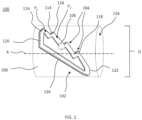
- FIG. 1 shows a diametric adjustment mechanism for an implantable medical device, according to some embodiments.
- the diametric adjustment mechanism 100 includes a track 102 defining a series of diametric setpoints 104, a rider 106 engaged with the track 102 and selectively movable along the track 102 between the series of diametric setpoints 104, and a biasing element 108 to promote movement of the rider 106 in a certain direction along the track 102.
- the diametric adjustment mechanism 100 also referred to herein simply as the adjustment mechanism 100, is coupled to an implantable medical device 200 ( FIG. 3 ).
- the series of diametric setpoints 104 includes at least two setpoints, for example, a first diametric setpoint 110 ( FIG.
- the diameter D of the adjustment mechanism 100 is either increased or decreased depending on the direction in which the rider 106 moves along the track 102.
- the rider 106 could move in a clockwise direction around the track 102 or in a counter-clockwise direction around the track 102 depending on the configuration of the track 102.
- the diameter d ( FIG. 3A ) of the implantable medical device 200 also increases or decreases.
- the series of diametric setpoints 104 correspond to a series of stop points spaced along the track 102 configured to keep the rider 106 at a certain location along the track 102 until a biasing force imparted by the biasing element 108 on the rider 106 is overcome.
- each of the stop points keep the adjustment mechanism 100 at a respective, desired diameter D until the biasing force is overcome and the rider 106 moves to the subsequent stop point.
- the biasing force can be overcome by application of a diametric force (e.g., a radial force applied in a radially outward direction from the longitudinal axis A of the adjustment mechanism 100), a magnetic force (e.g., applied externally through the skin of a patient), or any other applied force that exceeds the biasing force and to cause the rider 106 to move along the series of diametric setpoints 104.
- a diametric force e.g., a radial force applied in a radially outward direction from the longitudinal axis A of the adjustment mechanism 100
- a magnetic force e.g., applied externally through the skin of a patient
- the diametric force is an expansion force imparted on an interior of the implantable medical device 200 using a balloon catheter, although other methods of imparting an expansion force upon the adjustment mechanism 100 are also contemplate
- the series of diametric setpoints 104 can be any of a series of notches, steps, grooves, bends, curves, crooks, or any other configuration capable of keeping the rider 106 at a certain location along the track 102.
- the series of diametric setpoints 104 may include portions that are flat, upwardly angled, or otherwise inflected as compared to the rest of the track 102 so that the rider 106 may sit, rest, or lodge at the respective one of the series of setpoints 104 until the biasing force is overcome, as shown in FIG. 1 .
- the series of diametric setpoints 104 includes a first diametric setpoint 110 and a second diametric setpoint 112.
- the first diametric setpoint 110 corresponds to a first diameter D 1 of the adjustment mechanism 100 and the second diametric setpoint 112 corresponds to a second diameter D 2 of the adjustment mechanism 100.
- moving the rider 106 between the first diametric setpoint 110 and the second diametric setpoint 112 causes the diametric adjustment mechanism 100 to increase and/or decrease from the first diameter D 1 to the second diameter D 2 and, in turn, causes the implantable medical device 200 to also increase or decrease from a first device diameter d 1 to a second device diameter d 2 .
- the track 102 can include additional setpoints, as desired, for adjusting the diameter D of the adjustment mechanism 100.
- the track 102 can include an intermediate diametric setpoint 124 located between the first diametric setpoint 110 and the second diametric setpoint 112. Similar to the first and second diametric setpoints 110, 112, the intermediate diametric setpoint 124 corresponds to an intermediate diameter D i of the diametric adjustment mechanism 100, the intermediate diameter D i being between the first diameter D 1 and the second diameter D 2 .
- Additional diametric setpoints may allow for incremental adjustment of the adjustment mechanism 100 and/or the implantable medical device 200 between any number of diameters as desired. For example, in certain instances, a larger number of smaller, incremental diametric adjustments may be necessary or beneficial where, in other instances, fewer, larger adjustments may be desired.
- the track 102 defines a stepped path 114, as shown in FIG. 1 , with each of the series of diametric setpoints 104 spaced along the stepped path 114.
- the first diametric setpoint 110 is located at a first step location 116 along the stepped path 114 and the second diametric setpoint 112 is located at a second step location 118 along the stepped path 114.
- moving the rider 106 between the first diametric setpoint 110 (e.g., the first step location 116) and the second diametric setpoint 112 (e.g., the second step location 118) causes the adjustment mechanism 100 to increase and/or decrease from the first diameter D 1 to the second diameter D 2 .
- first step location 116 may be near a first end 120 of the track 102 and the second step location 118 may be near a second end 122 of the track 102.
- first and second step locations 116, 118 can be located anywhere along the track 102 as desired.
- the track 102 defines a first adjustment path P 1 .
- the first adjustment path P 1 may be, for example, between the first diametric setpoint 116 and the second diametric setpoint 118.
- the rider 106 can move along the first adjustment path P 1 to adjust the adjustment mechanism 100 between the first diameter D 1 and the second diameter D 2 .
- the first adjustment path P 1 may also be between the first diametric setpoint 116 and the intermediate diametric setpoint 124.
- the rider 106 can move along the first adjustment path P 1 from the first diametric setpoint 116 to the intermediate diametric setpoint 124 prior to moving to the second diametric setpoint 118.
- the track 102 also defines a second adjustment path P 2 .
- the rider 106 may then move along the second adjustment path P 2 from the intermediate diametric setpoint 124 to the second diametric setpoint 118.
- the track 102 may define a third adjustment path, a fourth adjustment path, or any number of adjustment paths between each setpoint of the series of diametric setpoints 104 as desired.
- the adjustment mechanism 100 can also be configured to increase in diameter as the rider 106 moves along the first and second adjustment paths P 1 , P 2 .
- the diameter D of the adjustment mechanism 100 may increase (i.e., from a smaller diameter to a larger diameter), and may further increase as the rider 106 moves along the second adjustment path P 2 from the intermediate setpoint 124 to the second diametric setpoint 118.
- the track also defines a return path 126 between the second diametric setpoint 112 and the first diametric setpoint 110.
- the return path 126 allows for diametric adjustment of the adjustment mechanism 100 from the second diameter D 2 to the first diameter D 1 .
- the return path 126 is located adjacent and may be located substantially parallel to the stepped path 114. In some embodiments, the return path 126 may be substantially straight such that the rider 106 can move continuously and uninterrupted from the second diametric setpoint 112 to the first diametric setpoint 110.
- the return path 126 allows for return of the rider 106 to its original location (e.g., the first step location 116) so that in use the rider 106 remains continually engaged with the track 102.
- the track 102 may define a continuous loop, as shown in FIG. 1 .
- the rider 106 can move along the stepped path 114 from the first diametric setpoint 110 to the second diametric setpoint 112 and then move along the return path 126 from the second diametric setpoint 112 to the first diametric setpoint 110 without disengaging from the track 102.
- the rider 106 and the track 102 are complementary features that are configured to remain slidably coupled during diametric adjustment.
- the rider 106 may be a projection, groove, or other feature capable of slidably engaging with the track 102.
- the track 102 may define a depression or relief feature capable of receiving the rider 106, or a raised rail or other feature on which the rider 106 traverses.
- the track 102 can include at least one of a groove, a channel, a notch, an indentation, a rail, or any other feature capable of receiving or otherwise engaging with the rider 106.
- the diametric adjustment mechanism 100 includes a biasing element 108, as shown in FIG. 1 .
- the biasing element 108 promotes movement of the rider in a certain, desired direction along the track 102.
- the biasing element 108 may bias or promote movement of the rider 106 toward the second diametric setpoint 112 when the rider 106 is at the first diametric setpoint 110, or toward the first diametric setpoint 110 when the rider 106 is at the second diametric setpoint 112.
- the biasing element 108 is configured to maintain the rider 106 at the first diametric setpoint 110 until the biasing force of the biasing element 108 is exceeded by the diametric force (i.e., from the catheter balloon, the magnet, or a bodily function such as, for example, a heartbeat) to move the rider 106 to the second diametric setpoint 112, at which movement of the rider 106 is halted until the biasing force of the biasing element 108 is again exceeded by the diametric force.
- the diametric force i.e., from the catheter balloon, the magnet, or a bodily function such as, for example, a heartbeat
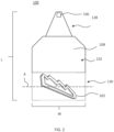
- FIG. 2 shows the diametric adjustment mechanism 100 coupled to the biasing element 108, according to some embodiments.
- the biasing element 108 is formed of a resilient material capable of imparting a bias on the rider 106, as discussed above.
- the biasing element 108 promotes movement of the rider 106 in a certain direction along the track 102.
- the biasing element 108 may be configured to bias the adjustment mechanism 100 toward the smaller diametric setpoint.
- the biasing element 108 may be configured to bias the adjustment mechanism 100 toward the smaller diametric setpoint (e.g., biasing the rider 106 in a direction along the track 102 from the first diametric setpoint 110 toward the second diametric setpoint 112).
- the biasing element 108 is formed of a substantially flat sheet of material capable of overlapping itself to form a generally tubular or cylindrical shape, as is shown in FIG. 1 .
- the biasing element 108 may include a length L extending from a first portion 128 to a second portion 130, and a width W, the width W being a dimension perpendicular to the length L.
- the biasing element 108 also includes an outer surface 132, an inner surface 134 ( FIG. 1 ), and a longitudinal axis A.
- the track 102 is coupled to the outer surface 132, near the second portion 130, of the biasing element 108 and the rider 106 is coupled to the inner surface 134, near the first portion 128, of the biasing element 108 such that, when the biasing element 108 is folded over itself and overlaps (e.g., the first portion 128 overlaps the second portion 130), the rider 106 engages the track 102 so that the rider 106 is slidably coupled to the track 102.
- FIGS. 3A to 3C show the adjustment mechanism 100 coupled to an implantable medical device 200 in the form of a tubular implant.
- the adjustment mechanism 100 can be coupled to the implantable medical device 200 such that, when the adjustment mechanism 100 changes from the first diameter D 1 to the second diameter D 2 , the implantable medical device 200 also changes from the first device diameter d 1 to the second device diameter d 2 .
- implantable medical devices 200 in the form of tubular implants may include stents and stent-grafts, among other tubular, cylindrically-shaped devices (e.g., heart valves, vascular filters, anastomosis devices, occluders, and others).
- FIG. 3A shows the diametric adjustment mechanism 100 coupled to the implantable medical device 200 in an expanded configuration or, in other words, at the first diameter D 1 .
- the rider 106 is located at the first diametric setpoint 110 (e.g., at the first step location 116).
- the first diametric setpoint 110 corresponds to the first diameter D 1 of the adjustment mechanism 100 and the first device diameter d 1 of the implantable medical device 200.
- the biasing element 108 can be a cylindrical member 136, also described as a collar 136, configured to surround an outer surface or a portion of the exterior surface of the implantable medical device 200.
- the collar 136 has elastic properties that impart the bias on the adjustment mechanism 100. As discussed above, when the biasing force is overcome by the diametric force, the rider 106 moves, for example, from the first diametric setpoint 110 to the second diametric setpoint 112, adjusting the diameters of the adjustment mechanism 100 and implantable medical device 200 as described above.
- FIG. 3B shows the adjustment mechanism 100 at the intermediate diameter D i .
- the rider 106 is located at the intermediate diametric setpoint 124.
- the intermediate diametric setpoint 124 corresponds to an intermediate diameter D i of the diametric adjustment mechanism 100 and an intermediate device diameter d i of the implantable medical device 200.
- movement of the rider 106 along the track 102 or, in some examples, along the stepped path 114 facilitates adjustment of the implantable medical device 200 from the first device diameter d 1 to the intermediate device diameter d i .
- FIG. 3C shows the adjustment mechanism 100 in a compressed configuration or, in other words, at the second diameter D 2 .
- the rider 106 is located at the second diametric setpoint 112 (e.g., at the second step location 118).
- the second diametric setpoint 112 corresponds to the second diameter D 2 of the adjustment mechanism 100 and the second device diameter d 2 of the implantable medical device 200.
- a method of adjusting the diameter d of the implantable medical device 200 includes imparting a first diametric force on the diametric adjustment mechanism 100.
- the first diametric force moves the rider 106 from the first diametric setpoint 110 to the second diametric setpoint 112 along the stepped path 114 according to a first configuration as can be seen in FIGS. 3A to 3C (configured to transition from a larger diameter to a smaller diameter under the first diametric force, which is a compressive force) or according to a second configuration as can be seen in FIGS. 4A to 4C (configured to transition from a smaller diameter to a larger diameter under the first diametric force F D1 , which is an expansion force).
- the first diametric force may be a constrictive or compressive force configured to alter the diameter d of the implantable medical device 200.
- the diametric force is imparted by a manual force applied through the skin (e.g., by hand) or a force applied using one or more transcatheter devices (e.g., a balloon catheter or other device capable of diametric adjustment).
- the diametric force may also be applied (whether internally or externally) as a magnetic force that interacts with the rider 106 and "forces" or moves the rider 106 along the track 102 between any setpoints of the series of diametric setpoints 104 as desired.
- the method also includes imparting a second diametric force on the diametric adjustment mechanism 100.
- the second diametric force releases the rider 106 from the second diametric setpoint 112 and allows movement of the rider 106 from the second diametric setpoint 112 to the first diametric setpoint 110 along the return path 126 (e.g., as a result of the biasing force).
- the first diametric force is an expanding force.
- the expanding force may be imparted on an interior of the implantable medical device 200 in a variety of ways such as with a balloon catheter, as discussed above.
- FIGS. 4A to 4C show the adjustment mechanism 100 and implantable medical device 200 as an incremental expansion force is applied.
- the rider 106 is positioned at the first diametric setpoint 110 and the implantable medical device 200 is at the second (e.g., reduced) device diameter d 2 .
- FIG. 4B shows the adjustment mechanism 100 after a first diametric force has been applied.
- the rider 106 is positioned at the intermediate diametric setpoint 124 and the implantable medical device 200 is at the intermediate device diameter d i .
- FIG. 4C shows the adjustment mechanism 100 after a second diametric force has been applied.
- the rider 106 is positioned at the second diametric setpoint 112 and the implantable medical device 200 is at the first (e.g., expanded) device diameter d 1 .
- the diametric force is imparted by a manual force applied through the skin (e.g., by hand) or a force applied using one or more transcatheter devices (e.g., a balloon catheter or other device capable of diametric adjustment).
- the diametric force may also be applied (whether internally or externally) as a magnetic force that interacts with the rider 106 and "forces" or moves the rider 106 along the track 102 from the first diametric setpoint 110 to the second diametric setpoint 112, from the second diametric setpoint 112 to the first diametric setpoint 110, and/or between any setpoints of the series of diametric setpoints 104 as desired.
- the rider 106 optionally includes a ferromagnetic material upon which an internal or external magnet may act. It should be understood that any other types of diametric forces F D may be used, as desired, to impart an applied force on the rider 106 and overcome the biasing force to move the rider 106 along the track 102.
- the adjustment mechanism 100 is optionally employed in a variety of applications.
- the adjustment mechanism 100 is optionally employed to control flow through an intrahepatic portosystemic shunt device (e.g., in association with devices such as W.L. Gore & Associates Inc.'s product sold under the trade name "GORE ® VIATORR ® TIPS Endoprosthesis.”
- the adjustment mechanism 100 is employed in an arteriovenous access application (e.g., to control flow through a fistula or graft, for example).
- the adjustment mechanism 100 is employed to control flow through a prosthetic valve (e.g., heart valve).
- a prosthetic valve e.g., heart valve
- the adjustment mechanism is employed to control flow in an aorta of a patient to control flow into the renal arteries of the patient (e.g., by controlling a diameter of a portion of an aortic stent graft).
- Methods of using the adjustment mechanism include a one-time adjustment, multiple adjustments, and adjustments of any frequency or periodicity (e.g., an adjustment per minute, hour, day, week, year, or per every heart beat).
- the adjustment mechanism 100 may be configured to adjust the diameter of a medical device with each of the patient's heartbeats.
- the adjustment mechanism 100 may have many small diametric setpoints that each require a small biasing force to adjust. Therefore, with each heartbeat, the mechanism 100 may incrementally increase in diameter until reaching its full diameter, at which point the mechanism 100 may reset to its minimum diameter and repeat the cycle.
- the mechanism 100 may also be configured to incrementally decrease in diameter until reaching its minimum diameter, at which point the mechanism 100 may reset to its maximum diameter and repeat. Such continuous increasing or decreasing of the adjustment mechanism 100 may prevent the patient's body from adjusting to a new pressure, flow, or other property created by the presence of the adjustment mechanism 100.
Landscapes
- Health & Medical Sciences (AREA)
- Engineering & Computer Science (AREA)
- Biomedical Technology (AREA)
- Cardiology (AREA)
- Oral & Maxillofacial Surgery (AREA)
- Transplantation (AREA)
- Heart & Thoracic Surgery (AREA)
- Vascular Medicine (AREA)
- Life Sciences & Earth Sciences (AREA)
- Animal Behavior & Ethology (AREA)
- General Health & Medical Sciences (AREA)
- Public Health (AREA)
- Veterinary Medicine (AREA)
- Prostheses (AREA)
- Surgical Instruments (AREA)
- Media Introduction/Drainage Providing Device (AREA)
Claims (14)
- Durchmesseranpassungsmechanismus (100) für eine implantierbare medizinische Vorrichtung (200), wobei der Durchmesseranpassungsmechanismus (100) Folgendes umfasst:eine Bahn (102), die eine Reihe von Durchmessersollwerten (104) definiert, die einen ersten Durchmessersollwert (110) und einen zweiten Durchmessersollwert (112) enthält, einen ersten Anpassungsweg (P1), der von dem ersten Durchmessersollwert (110) zu dem zweiten Durchmessersollwert (112) definiert ist, und einen Rückweg (126), der von dem zweiten Durchmessersollwert (112) zu dem ersten Durchmessersollwert (110) definiert ist, wobei der Rückweg (126) benachbart zu dem ersten Anpassungsweg (P1) ist;einen Reiter (106), der mit der Bahn (102) in Eingriff steht, sodass der Reiter (106) selektiv entlang der Bahn (102) von dem ersten Durchmessersollwert (110) zu dem zweiten Durchmessersollwert (112) und von dem zweiten Durchmessersollwert (112) zu dem ersten Durchmessersollwert (110) bewegbar ist; undein Vorspannelement (108), das den Reiter (106) in Richtung des ersten Durchmessersollwerts (110) vorspannt, wenn sich der Reiter (106) an dem zweiten Durchmessersollwert (112) befindet.
- Anpassungsmechanismus (100) nach Anspruch 1, wobei die Bahn (102) einen gestuften Weg (114) definiert, wobei sich der erste Durchmessersollwert (110) an einer ersten Stufenposition (116) des gestuften Wegs (114) und der zweite Durchmessersollwert (112) an einer zweiten Stufenposition (118) des gestuften Wegs (114) befindet.
- Anpassungsmechanismus (100) nach einem vorhergehenden Anspruch, wobei die Bahn (102) einen Zwischendurchmessersollwert (124) zwischen dem ersten Durchmessersollwert (110) und dem zweiten Durchmessersollwert (114) definiert, wobei der Reiter (106) mit der Bahn (102) in Eingriff steht, sodass der Reiter (106) selektiv entlang der Bahn (102) von dem ersten Durchmessersollwert (110) zu dem Zwischendurchmessersollwert (124), bevor er sich zu dem zweiten Durchmessersollwert (112) bewegt, und von dem Zwischendurchmessersollwert (124) zu dem zweiten Durchmessersollwert (112) bewegbar ist.
- Anpassungsmechanismus (100) nach einem vorhergehenden Anspruch, wobei das Vorspannelement (108) eine Hülse mit elastischen Eigenschaften ist.
- Anpassungsmechanismus (100) nach einem vorhergehenden Anspruch, wobei die Bahn (102) eine Endlosschleife definiert.
- Anpassungsmechanismus (100) nach einem vorhergehenden Anspruch, wobei die Bahn (102) mindestens eines von einer Nut, einem Kanal, einer Kerbe, einer Einbuchtung und einer Schiene enthält.
- Anpassungsmechanismus (100) nach einem vorhergehenden Anspruch, wobei das Vorspannelement (108) dazu konfiguriert ist, den Reiter (106) an dem ersten Durchmessersollwert (110) zu halten, bis eine Vorspannkraft des Vorspannelements (108) durch eine externe Kraft überschritten wird, um den Reiter (106) zu dem zweiten Durchmessersollwert (112) zu bewegen, an dem das Vorspannelement (108) den Reiter (106) hält, bis die Vorspannkraft des Vorspannelements (108) durch eine externe Kraft überschritten wird.
- Anpassungsmechanismus (100) nach einem vorhergehenden Anspruch, wobei der Reiter (106) ein Vorsprung ist und die Bahn (102) eine Vertiefung ist, die den Vorsprung verschiebbar aufnimmt.
- Medizinische Vorrichtung (200), das ein röhrenförmiges Implantat und den Anpassungsmechanismus (100) nach einem vorhergehenden Anspruch, der mit dem röhrenförmigen Implantat gekoppelt ist, enthält, wobei das Vorspannelement (108) des Anpassungsmechanismus (100) eine Hülse enthält, die aus einem federnden Material gebildet ist, wobei die Hülse mit dem röhrenförmigen Implantat gekoppelt ist.
- Medizinische Vorrichtung (200) nach Anspruch 9, wobei das Vorspannelement (108) sich selbst überlappt, um die Hülse zu bilden.
- Medizinische Vorrichtung (200) nach einem der Ansprüche 9-10, wobei das Vorspannelement (108) einen ersten Abschnitt (128) und einen zweiten Abschnitt (130) enthält und wobei der erste Abschnitt (128) den zweiten Abschnitt (130) überlappt, um den Reiter (106) mit der Bahn (102) in Eingriff zu bringen.
- Verfahren zum Anpassen des Durchmessers der medizinischen Vorrichtung (200) nach einem der vorhergehenden Ansprüche, wobei das Verfahren Folgendes umfasst:Ausüben einer ersten diametralen Kraft auf das röhrenförmige Element, um den Reiter entlang eines ersten Anpassungswegs (P1) von dem ersten Durchmessersollwert (110) zu dem zweiten Durchmessersollwert (112) zu bewegen; undAusüben einer zweiten diametralen Kraft auf das röhrenförmige Element, um den Reiter (106) von dem zweiten Durchmessersollwert (112) zu dem ersten Durchmessersollwert (110) entlang eines Rückwegs (126) zu bewegen, wobei der Rückweg (126) benachbart zu dem ersten Anpassungsweg (P1) ist.
- Verfahren nach Anspruch 12, wobei die diametrale Kraft eine Expansionskraft ist, die mit einem Ballonkatheter auf ein Inneres des röhrenförmigen Implantats (200) ausgeübt wird.
- Verfahren nach einem der Ansprüche 12 bis 13, wobei ein Bewegen des Reiters (106) von dem ersten Durchmessersollwert (110) zu dem zweiten Durchmessersollwert (112) den Durchmesser der medizinischen Vorrichtung (200) von einem ersten Durchmesser (D1) auf einen zweiten Durchmesser (D2) anpasst und wobei ein Bewegen des Reiters (106) von dem zweiten Durchmessersollwert (112) zu dem ersten Durchmessersollwert (110) den Durchmesser der medizinischen Vorrichtung (200) von dem zweiten Durchmesser (D2) auf den ersten Durchmesser (D1) anpasst.
Applications Claiming Priority (2)
| Application Number | Priority Date | Filing Date | Title |
|---|---|---|---|
| US201862683295P | 2018-06-11 | 2018-06-11 | |
| PCT/US2019/035993 WO2019241057A1 (en) | 2018-06-11 | 2019-06-07 | In vivo adjustment mechanism and associated systems and methods |
Publications (2)
| Publication Number | Publication Date |
|---|---|
| EP3801405A1 EP3801405A1 (de) | 2021-04-14 |
| EP3801405B1 true EP3801405B1 (de) | 2024-12-18 |
Family
ID=67263026
Family Applications (1)
| Application Number | Title | Priority Date | Filing Date |
|---|---|---|---|
| EP19739740.9A Active EP3801405B1 (de) | 2018-06-11 | 2019-06-07 | In-vivo-anpassungsmechanismus und zugehörige systeme und verfahren |
Country Status (8)
| Country | Link |
|---|---|
| US (2) | US11806261B2 (de) |
| EP (1) | EP3801405B1 (de) |
| JP (1) | JP7100718B2 (de) |
| CN (1) | CN112261920B (de) |
| AU (1) | AU2019284293B2 (de) |
| CA (1) | CA3100547C (de) |
| ES (1) | ES3015957T3 (de) |
| WO (1) | WO2019241057A1 (de) |
Families Citing this family (1)
| Publication number | Priority date | Publication date | Assignee | Title |
|---|---|---|---|---|
| WO2025109602A1 (en) | 2023-11-24 | 2025-05-30 | Restore Medical Ltd. | Adjustable constrictor for reducing the diameter of implantable medical device |
Family Cites Families (15)
| Publication number | Priority date | Publication date | Assignee | Title |
|---|---|---|---|---|
| US5441515A (en) * | 1993-04-23 | 1995-08-15 | Advanced Cardiovascular Systems, Inc. | Ratcheting stent |
| US6033436A (en) * | 1998-02-17 | 2000-03-07 | Md3, Inc. | Expandable stent |
| DE19951148A1 (de) * | 1999-10-12 | 2001-04-19 | Technomed Ges Fuer Med Und Med | Kapselspannring mit einem bogenförmigen elastischen Element |
| US7578843B2 (en) | 2002-07-16 | 2009-08-25 | Medtronic, Inc. | Heart valve prosthesis |
| US8551162B2 (en) * | 2002-12-20 | 2013-10-08 | Medtronic, Inc. | Biologically implantable prosthesis |
| AU2006218782C1 (en) | 2005-02-28 | 2012-07-05 | Cook Medical Technologies Llc | Removable coiled stent |
| US9149378B2 (en) * | 2005-08-02 | 2015-10-06 | Reva Medical, Inc. | Axially nested slide and lock expandable device |
| US20070112418A1 (en) | 2005-11-14 | 2007-05-17 | Boston Scientific Scimed, Inc. | Stent with spiral side-branch support designs |
| US8435284B2 (en) | 2005-12-14 | 2013-05-07 | Boston Scientific Scimed, Inc. | Telescoping bifurcated stent |
| US9408607B2 (en) * | 2009-07-02 | 2016-08-09 | Edwards Lifesciences Cardiaq Llc | Surgical implant devices and methods for their manufacture and use |
| US20110172692A1 (en) | 2008-06-13 | 2011-07-14 | Steven Wu | Hemodialysis arterio-venous graft with a ring-like diameter-adjustable device |
| WO2012018779A2 (en) * | 2010-08-02 | 2012-02-09 | Children's Medical Center Corporation | Expandable valve and method of use |
| WO2016167002A1 (ja) * | 2015-04-17 | 2016-10-20 | 株式会社カネカ | 医療用管状体 |
| US10849731B2 (en) | 2016-11-08 | 2020-12-01 | W. L. Gore & Associates, Inc. | Cell encapsulation devices containing structural spacers |
| WO2018156613A1 (en) * | 2017-02-21 | 2018-08-30 | Trustees Of Tufts College | Silk fibroin tracheal stent |
-
2019
- 2019-06-07 US US17/251,028 patent/US11806261B2/en active Active
- 2019-06-07 JP JP2020568812A patent/JP7100718B2/ja active Active
- 2019-06-07 EP EP19739740.9A patent/EP3801405B1/de active Active
- 2019-06-07 CN CN201980038719.5A patent/CN112261920B/zh active Active
- 2019-06-07 ES ES19739740T patent/ES3015957T3/es active Active
- 2019-06-07 WO PCT/US2019/035993 patent/WO2019241057A1/en not_active Ceased
- 2019-06-07 CA CA3100547A patent/CA3100547C/en active Active
- 2019-06-07 AU AU2019284293A patent/AU2019284293B2/en active Active
-
2023
- 2023-10-31 US US18/498,833 patent/US20240139004A1/en active Pending
Also Published As
| Publication number | Publication date |
|---|---|
| CA3100547A1 (en) | 2019-12-19 |
| WO2019241057A1 (en) | 2019-12-19 |
| AU2019284293A1 (en) | 2021-01-28 |
| JP2021526916A (ja) | 2021-10-11 |
| AU2019284293B2 (en) | 2022-08-11 |
| US20210169667A1 (en) | 2021-06-10 |
| EP3801405A1 (de) | 2021-04-14 |
| CN112261920A (zh) | 2021-01-22 |
| JP7100718B2 (ja) | 2022-07-13 |
| ES3015957T3 (en) | 2025-05-08 |
| US20240139004A1 (en) | 2024-05-02 |
| CA3100547C (en) | 2023-10-03 |
| US11806261B2 (en) | 2023-11-07 |
| CN112261920B (zh) | 2024-05-24 |
Similar Documents
| Publication | Publication Date | Title |
|---|---|---|
| EP2015709B1 (de) | Transkatheter-herzklappenprothesen | |
| CN108366856B (zh) | 用于心脏瓣膜假体的经导管植入的递送系统 | |
| US10478290B2 (en) | Expandable stent valve | |
| EP3311778B1 (de) | Doppelklappenprothese für transkatheterklappenimplantation | |
| US20130204176A1 (en) | Arteriovenous Shunt Having a Moveable Valve | |
| US20140088680A1 (en) | Prosthesis for Transcatheter Valve Implantation | |
| WO2014138194A1 (en) | Prosthesis for transcatheter valve implantation | |
| JP2011087943A (ja) | 体内の径路の補綴による修復 | |
| EP3512467A1 (de) | Herzklappenquetschvorrichtungen und einführungssysteme | |
| JP2003518984A (ja) | 管腔を介する人工弁及び静脈人工弁の製造方法及び給送方法 | |
| JP2008036418A6 (ja) | 体内の径路の補綴による修復 | |
| CN103517685A (zh) | 可植入和可去除的可定制身体管道 | |
| JPH10503399A (ja) | 輪状形成用拡張性リング | |
| US9913741B2 (en) | Control handle for self-expandable medical devices | |
| JP2016185362A (ja) | ステントグラフトを展開するための装置 | |
| US20240139004A1 (en) | In vivo adjustment mechanism and associated systems and methods | |
| US12496180B2 (en) | Vascular prosthesis | |
| JP2007167652A (ja) | コイル状ステントを含む人工器官およびその使用方法 | |
| CN219896030U (zh) | 用于植入人工瓣膜的持瓣器 | |
| WO2026026756A1 (zh) | 腔内植入系统 |
Legal Events
| Date | Code | Title | Description |
|---|---|---|---|
| STAA | Information on the status of an ep patent application or granted ep patent |
Free format text: STATUS: UNKNOWN |
|
| STAA | Information on the status of an ep patent application or granted ep patent |
Free format text: STATUS: THE INTERNATIONAL PUBLICATION HAS BEEN MADE |
|
| PUAI | Public reference made under article 153(3) epc to a published international application that has entered the european phase |
Free format text: ORIGINAL CODE: 0009012 |
|
| STAA | Information on the status of an ep patent application or granted ep patent |
Free format text: STATUS: REQUEST FOR EXAMINATION WAS MADE |
|
| 17P | Request for examination filed |
Effective date: 20201123 |
|
| AK | Designated contracting states |
Kind code of ref document: A1 Designated state(s): AL AT BE BG CH CY CZ DE DK EE ES FI FR GB GR HR HU IE IS IT LI LT LU LV MC MK MT NL NO PL PT RO RS SE SI SK SM TR |
|
| AX | Request for extension of the european patent |
Extension state: BA ME |
|
| DAV | Request for validation of the european patent (deleted) | ||
| DAX | Request for extension of the european patent (deleted) | ||
| RAP3 | Party data changed (applicant data changed or rights of an application transferred) |
Owner name: W.L. GORE & ASSOCIATES, INC. |
|
| GRAP | Despatch of communication of intention to grant a patent |
Free format text: ORIGINAL CODE: EPIDOSNIGR1 |
|
| STAA | Information on the status of an ep patent application or granted ep patent |
Free format text: STATUS: GRANT OF PATENT IS INTENDED |
|
| INTG | Intention to grant announced |
Effective date: 20240722 |
|
| P01 | Opt-out of the competence of the unified patent court (upc) registered |
Free format text: CASE NUMBER: APP_48512/2024 Effective date: 20240823 |
|
| GRAS | Grant fee paid |
Free format text: ORIGINAL CODE: EPIDOSNIGR3 |
|
| GRAA | (expected) grant |
Free format text: ORIGINAL CODE: 0009210 |
|
| STAA | Information on the status of an ep patent application or granted ep patent |
Free format text: STATUS: THE PATENT HAS BEEN GRANTED |
|
| AK | Designated contracting states |
Kind code of ref document: B1 Designated state(s): AL AT BE BG CH CY CZ DE DK EE ES FI FR GB GR HR HU IE IS IT LI LT LU LV MC MK MT NL NO PL PT RO RS SE SI SK SM TR |
|
| REG | Reference to a national code |
Ref country code: CH Ref legal event code: EP |
|
| REG | Reference to a national code |
Ref country code: DE Ref legal event code: R096 Ref document number: 602019063654 Country of ref document: DE |
|
| REG | Reference to a national code |
Ref country code: IE Ref legal event code: FG4D |
|
| REG | Reference to a national code |
Ref country code: LT Ref legal event code: MG9D |
|
| PG25 | Lapsed in a contracting state [announced via postgrant information from national office to epo] |
Ref country code: HR Free format text: LAPSE BECAUSE OF FAILURE TO SUBMIT A TRANSLATION OF THE DESCRIPTION OR TO PAY THE FEE WITHIN THE PRESCRIBED TIME-LIMIT Effective date: 20241218 |
|
| PG25 | Lapsed in a contracting state [announced via postgrant information from national office to epo] |
Ref country code: FI Free format text: LAPSE BECAUSE OF FAILURE TO SUBMIT A TRANSLATION OF THE DESCRIPTION OR TO PAY THE FEE WITHIN THE PRESCRIBED TIME-LIMIT Effective date: 20241218 |
|
| PG25 | Lapsed in a contracting state [announced via postgrant information from national office to epo] |
Ref country code: BG Free format text: LAPSE BECAUSE OF FAILURE TO SUBMIT A TRANSLATION OF THE DESCRIPTION OR TO PAY THE FEE WITHIN THE PRESCRIBED TIME-LIMIT Effective date: 20241218 |
|
| PG25 | Lapsed in a contracting state [announced via postgrant information from national office to epo] |
Ref country code: NO Free format text: LAPSE BECAUSE OF FAILURE TO SUBMIT A TRANSLATION OF THE DESCRIPTION OR TO PAY THE FEE WITHIN THE PRESCRIBED TIME-LIMIT Effective date: 20250318 |
|
| REG | Reference to a national code |
Ref country code: NL Ref legal event code: MP Effective date: 20241218 |
|
| PG25 | Lapsed in a contracting state [announced via postgrant information from national office to epo] |
Ref country code: LV Free format text: LAPSE BECAUSE OF FAILURE TO SUBMIT A TRANSLATION OF THE DESCRIPTION OR TO PAY THE FEE WITHIN THE PRESCRIBED TIME-LIMIT Effective date: 20241218 Ref country code: GR Free format text: LAPSE BECAUSE OF FAILURE TO SUBMIT A TRANSLATION OF THE DESCRIPTION OR TO PAY THE FEE WITHIN THE PRESCRIBED TIME-LIMIT Effective date: 20250319 |
|
| PG25 | Lapsed in a contracting state [announced via postgrant information from national office to epo] |
Ref country code: RS Free format text: LAPSE BECAUSE OF FAILURE TO SUBMIT A TRANSLATION OF THE DESCRIPTION OR TO PAY THE FEE WITHIN THE PRESCRIBED TIME-LIMIT Effective date: 20250318 |
|
| REG | Reference to a national code |
Ref country code: ES Ref legal event code: FG2A Ref document number: 3015957 Country of ref document: ES Kind code of ref document: T3 Effective date: 20250508 |
|
| PG25 | Lapsed in a contracting state [announced via postgrant information from national office to epo] |
Ref country code: NL Free format text: LAPSE BECAUSE OF FAILURE TO SUBMIT A TRANSLATION OF THE DESCRIPTION OR TO PAY THE FEE WITHIN THE PRESCRIBED TIME-LIMIT Effective date: 20241218 |
|
| REG | Reference to a national code |
Ref country code: AT Ref legal event code: MK05 Ref document number: 1751628 Country of ref document: AT Kind code of ref document: T Effective date: 20241218 |
|
| PG25 | Lapsed in a contracting state [announced via postgrant information from national office to epo] |
Ref country code: SM Free format text: LAPSE BECAUSE OF FAILURE TO SUBMIT A TRANSLATION OF THE DESCRIPTION OR TO PAY THE FEE WITHIN THE PRESCRIBED TIME-LIMIT Effective date: 20241218 |
|
| PG25 | Lapsed in a contracting state [announced via postgrant information from national office to epo] |
Ref country code: PL Free format text: LAPSE BECAUSE OF FAILURE TO SUBMIT A TRANSLATION OF THE DESCRIPTION OR TO PAY THE FEE WITHIN THE PRESCRIBED TIME-LIMIT Effective date: 20241218 |
|
| PGFP | Annual fee paid to national office [announced via postgrant information from national office to epo] |
Ref country code: DE Payment date: 20250520 Year of fee payment: 7 |
|
| PGFP | Annual fee paid to national office [announced via postgrant information from national office to epo] |
Ref country code: GB Payment date: 20250520 Year of fee payment: 7 |
|
| PG25 | Lapsed in a contracting state [announced via postgrant information from national office to epo] |
Ref country code: IS Free format text: LAPSE BECAUSE OF FAILURE TO SUBMIT A TRANSLATION OF THE DESCRIPTION OR TO PAY THE FEE WITHIN THE PRESCRIBED TIME-LIMIT Effective date: 20250418 |
|
| PGFP | Annual fee paid to national office [announced via postgrant information from national office to epo] |
Ref country code: IT Payment date: 20250520 Year of fee payment: 7 |
|
| PG25 | Lapsed in a contracting state [announced via postgrant information from national office to epo] |
Ref country code: PT Free format text: LAPSE BECAUSE OF FAILURE TO SUBMIT A TRANSLATION OF THE DESCRIPTION OR TO PAY THE FEE WITHIN THE PRESCRIBED TIME-LIMIT Effective date: 20250421 |
|
| PG25 | Lapsed in a contracting state [announced via postgrant information from national office to epo] |
Ref country code: EE Free format text: LAPSE BECAUSE OF FAILURE TO SUBMIT A TRANSLATION OF THE DESCRIPTION OR TO PAY THE FEE WITHIN THE PRESCRIBED TIME-LIMIT Effective date: 20241218 |
|
| PGFP | Annual fee paid to national office [announced via postgrant information from national office to epo] |
Ref country code: FR Payment date: 20250520 Year of fee payment: 7 |
|
| PG25 | Lapsed in a contracting state [announced via postgrant information from national office to epo] |
Ref country code: RO Free format text: LAPSE BECAUSE OF FAILURE TO SUBMIT A TRANSLATION OF THE DESCRIPTION OR TO PAY THE FEE WITHIN THE PRESCRIBED TIME-LIMIT Effective date: 20241218 Ref country code: AT Free format text: LAPSE BECAUSE OF FAILURE TO SUBMIT A TRANSLATION OF THE DESCRIPTION OR TO PAY THE FEE WITHIN THE PRESCRIBED TIME-LIMIT Effective date: 20241218 |
|
| PG25 | Lapsed in a contracting state [announced via postgrant information from national office to epo] |
Ref country code: SK Free format text: LAPSE BECAUSE OF FAILURE TO SUBMIT A TRANSLATION OF THE DESCRIPTION OR TO PAY THE FEE WITHIN THE PRESCRIBED TIME-LIMIT Effective date: 20241218 |
|
| PG25 | Lapsed in a contracting state [announced via postgrant information from national office to epo] |
Ref country code: CZ Free format text: LAPSE BECAUSE OF FAILURE TO SUBMIT A TRANSLATION OF THE DESCRIPTION OR TO PAY THE FEE WITHIN THE PRESCRIBED TIME-LIMIT Effective date: 20241218 |
|
| PG25 | Lapsed in a contracting state [announced via postgrant information from national office to epo] |
Ref country code: SE Free format text: LAPSE BECAUSE OF FAILURE TO SUBMIT A TRANSLATION OF THE DESCRIPTION OR TO PAY THE FEE WITHIN THE PRESCRIBED TIME-LIMIT Effective date: 20241218 |
|
| REG | Reference to a national code |
Ref country code: DE Ref legal event code: R097 Ref document number: 602019063654 Country of ref document: DE |
|
| PGFP | Annual fee paid to national office [announced via postgrant information from national office to epo] |
Ref country code: ES Payment date: 20250701 Year of fee payment: 7 |
|
| PG25 | Lapsed in a contracting state [announced via postgrant information from national office to epo] |
Ref country code: DK Free format text: LAPSE BECAUSE OF FAILURE TO SUBMIT A TRANSLATION OF THE DESCRIPTION OR TO PAY THE FEE WITHIN THE PRESCRIBED TIME-LIMIT Effective date: 20241218 |
|
| PLBE | No opposition filed within time limit |
Free format text: ORIGINAL CODE: 0009261 |
|
| STAA | Information on the status of an ep patent application or granted ep patent |
Free format text: STATUS: NO OPPOSITION FILED WITHIN TIME LIMIT |
|
| REG | Reference to a national code |
Ref country code: CH Ref legal event code: L10 Free format text: ST27 STATUS EVENT CODE: U-0-0-L10-L00 (AS PROVIDED BY THE NATIONAL OFFICE) Effective date: 20251029 |
|
| 26N | No opposition filed |
Effective date: 20250919 |
|
| REG | Reference to a national code |
Ref country code: CH Ref legal event code: H13 Free format text: ST27 STATUS EVENT CODE: U-0-0-H10-H13 (AS PROVIDED BY THE NATIONAL OFFICE) Effective date: 20260127 |
|
| PG25 | Lapsed in a contracting state [announced via postgrant information from national office to epo] |
Ref country code: MC Free format text: LAPSE BECAUSE OF FAILURE TO SUBMIT A TRANSLATION OF THE DESCRIPTION OR TO PAY THE FEE WITHIN THE PRESCRIBED TIME-LIMIT Effective date: 20241218 |
|
| PG25 | Lapsed in a contracting state [announced via postgrant information from national office to epo] |
Ref country code: LU Free format text: LAPSE BECAUSE OF NON-PAYMENT OF DUE FEES Effective date: 20250607 |
|
| REG | Reference to a national code |
Ref country code: BE Ref legal event code: MM Effective date: 20250630 |
|
| PG25 | Lapsed in a contracting state [announced via postgrant information from national office to epo] |
Ref country code: IE Free format text: LAPSE BECAUSE OF NON-PAYMENT OF DUE FEES Effective date: 20250607 |
|
| PG25 | Lapsed in a contracting state [announced via postgrant information from national office to epo] |
Ref country code: BE Free format text: LAPSE BECAUSE OF NON-PAYMENT OF DUE FEES Effective date: 20250630 |
|
| PG25 | Lapsed in a contracting state [announced via postgrant information from national office to epo] |
Ref country code: CH Free format text: LAPSE BECAUSE OF NON-PAYMENT OF DUE FEES Effective date: 20250630 |