EP3801352B1 - Vorrichtung zur erleichterung des anziehens eines kleidungsstücks - Google Patents
Vorrichtung zur erleichterung des anziehens eines kleidungsstücks Download PDFInfo
- Publication number
- EP3801352B1 EP3801352B1 EP19810690.8A EP19810690A EP3801352B1 EP 3801352 B1 EP3801352 B1 EP 3801352B1 EP 19810690 A EP19810690 A EP 19810690A EP 3801352 B1 EP3801352 B1 EP 3801352B1
- Authority
- EP
- European Patent Office
- Prior art keywords
- opening
- cuff
- arms
- initial
- cuff opening
- Prior art date
- Legal status (The legal status is an assumption and is not a legal conclusion. Google has not performed a legal analysis and makes no representation as to the accuracy of the status listed.)
- Active
Links
Images


Classifications
-
- A—HUMAN NECESSITIES
- A61—MEDICAL OR VETERINARY SCIENCE; HYGIENE
- A61B—DIAGNOSIS; SURGERY; IDENTIFICATION
- A61B42/00—Surgical gloves; Finger-stalls specially adapted for surgery; Devices for handling or treatment thereof
- A61B42/50—Devices for putting-on or removing
-
- A—HUMAN NECESSITIES
- A47—FURNITURE; DOMESTIC ARTICLES OR APPLIANCES; COFFEE MILLS; SPICE MILLS; SUCTION CLEANERS IN GENERAL
- A47G—HOUSEHOLD OR TABLE EQUIPMENT
- A47G25/00—Household implements used in connection with wearing apparel; Dress, hat or umbrella holders
- A47G25/90—Devices for domestic use for assisting in putting-on or pulling-off clothing, e.g. stockings or trousers
- A47G25/904—Devices for domestic use for assisting in putting-on or pulling-off clothing, e.g. stockings or trousers for gloves
Definitions
- the present invention relates to an apparatus arranged for facilitating donning a garment comprising a cuff on a part of a human body.
- the embodiments of the present invention are often described in relation to gloves, such as disposable and/or sterile gloves.
- the present invention is not limited to usage in connection with gloves. Instead, the present invention may be generally utilized for donning essentially any type of garment on essentially any body part.
- Disposable gloves are today used by employees in a number of different areas, such as e.g. in the health care sector and the food industry. Disposable gloves are typically worn to protect the hands of the user and/or to prevent spreading of bacteria and other agents. Due to stricter hygienic requirements and safety aspects, the use of disposable gloves is increasing and is likely to continue to increase in the future.
- WO2016/174672 shows known glove donning systems. Particularly, WO2016/174672 shows a glove donning system according to the preamble of claim 1.
- One disadvantage with using disposable gloves is that it may be difficult and time consuming to put them on, especially if the gloves are tight and/or the hands are damp. In addition, the risk of damaging a glove when it is being put on is high. These drawbacks may not be that severe for persons which only occasionally uses disposable gloves. However, a lot of persons working with disposable gloves need to regularly change gloves. For example, a nurse typically puts on a new pair of gloves for each new patient, and a person working behind a deli counter puts on a new pair of gloves for each new customer. Hence, in certain professions, many glove changes are performed per day per employee. If each of these glove changes is time consuming, there are major time losses and thereby costs associated with the changing of disposable gloves.
- a conventional glove donning machine uses vacuum or suction to inflate the glove and allow the hand to be inserted into the glove.
- vacuum or suction One disadvantage with using vacuum or suction is the noise produced by the vacuum pump.
- suction power such that the glove can be opened properly.
- Other types of known glove donning machines rely on complex movement of mechanical parts and requires advance mechanical structures which may be prone to malfunction.
- An objective of embodiments of the present invention is to provide a solution which mitigates or solves the drawbacks and problems of prior art.
- an apparatus arranged for facilitating donning a garment comprising a cuff on a part of a human body according to independent claim 1.
- first and the second cuff opening assemblies can expand a cuff of a garment using rotating arms, i.e. the first and second arms rotating around their first and second geometrical axes, respectively.
- rotating arms i.e. the first and second arms rotating around their first and second geometrical axes, respectively.
- a further advantage is that the first and second distal ends can be rotated and separated from each other in one movement. Thereby, a substantial expansion of the cuff of the glove can be achieved in a simple and fast way.
- first and second arms can be integrated with the first and second shafts, respectively.
- a flexible construction is achieved, allowing e.g. the arms and shafts to be hollow such that an air tube can be led through a shaft and further out through an arm.
- the first and second distal ends are inserted into a cuff of a garment placed in the donning position when the first and second arms are rotated around the first and second geometrical axes, respectively, from the initial position to the opening position.
- An advantage with this embodiment is that the cuff of the garment is expanded by the rotation of the arms inside the garment.
- An advantage with this embodiment is that the first and second arms of the first and second cuff opening assemblies, respectively, are separated in two directions by the above mentioned rotational movement, which efficiently opens the cuff to facilitate donning.
- An advantage with this embodiment is that the first and second arms of the first and second cuff opening assemblies, respectively, are close together in the initial position and can thereby easily be inserted into the opening/cuff of the garment.
- An advantage with this embodiment is that the first and second arms of the first and second cuff opening assemblies, respectively, are separated from each other in the opening position such that the cuff of the garment is expanded, whereby donning is facilitated.
- first and second arms are more flexible and can provide a large/substantial movement within a small space/cabinet of the apparatus, whereby a compact apparatus is provided.
- At least one of the first proximal part and the first distal part and the second proximal part and the second distal part, respectively, are resiliently connected by means of one or more in the group of:
- An advantage with this example is that the first and second distal parts of the first and second arms, respectively, can be arranged to allow the first and second arms to easily be inserted into the opening/cuff of the garment in the initial position.
- An advantage with this example is that the angles between the first and second distal parts are affected by the force created when the cuff opening assemblies are in contact with the inside of the garment in the subsequent position.
- An advantage with this example is that the first and second arms are arranged to expand the garment in the subsequent position to facilitate donning.
- the first subsequent angle, the second subsequent angle, the third subsequent angle, and the fourth subsequent angle are approximately 180 degrees.
- first and second arms are providing a large/substantial expansion of the garment in the opening position. Furthermore, the first and second arms are straight, i.e. the angle is 180 degrees, in the opening position which, means that they are out of the way for a hand as the garment is donned on the hand of a user. According to an embodiment of the invention,
- An advantage with this embodiment is that a synchronized and smooth rotation of the first and second arms can be achieved.
- An advantage with this embodiment is that a synchronized and smooth rotation of the first and second arms of the first and second cuff opening assemblies, respectively, can be achieved.
- the at least one cuff opening arrangement further comprises:
- the at least one rotation providing means includes:
- An advantage with this embodiment is that the rotational movement is provided by a mechanical rotation means, which is reliable and dependable.
- the at least one rotation providing means comprises:
- the apparatus further includes
- the at least one rotation providing means comprises:
- the at least one rotation providing means comprises:
- An advantage with this embodiment is that a synchronized rotation of the first and second arms of the first and second cuff opening arrangements, respectively, can be achieved.
- the garment fetching arrangement utilizes suction for fetching the garment from the garment storage and placing the garment in the donning position.
- suction provides a simple, dependable, and proven way of attaching the garment to the fetching arrangement. Suction is further gentle on the garment.
- the garment fetching arrangement comprises:
- An advantage with this example is that the risk that both sides of the garment is attached to the fetching arrangement is reduced.
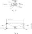
- Fig. 1a-b schematically illustrates an apparatus 800 according to various embodiments of the invention.
- Fig. 1a shows a side view of the apparatus 800
- Fig. 1b shows a top view of the apparatus 800.
- the apparatus 800 is arranged for facilitating donning a garment comprising a cuff on a part of a human body.
- the garment is a glove 52 and the apparatus 800 is arranged for donning two such gloves 52, one on each hand of a user.
- an apparatus 800 may be arranged for facilitating donning the other type of garment, e.g. donning a sock on a foot of a user.
- the apparatus 800 may comprise a garment fetching arrangement 50 arranged to fetch a glove 52 from a garment storage 54 and place the glove 52 in a donning position P donning .
- the garment fetching arrangement 50 comprises a moveable arm using suction to fetch the gloves 52.
- the garment fetching arrangement 50 in Fig. 1a-b is arranged to fetch two gloves 52 at a time, one glove 52 from a first glove storage 54a and another glove 52 from a second glove storage 54b, shown in Fig. 1b .
- less or more than two glove storages 54a, 54b may be used.
- Each glove storage 54a, 54b may comprise a stack of gloves 52.
- the apparatus 800 may further comprise at least one cuff opening arrangement 600, 700 arranged to open a cuff of a glove 52 in the donning position P donning .
- Each cuff opening arrangement 600, 700 can open one glove at a time.
- one glove at a time can be applied to a hand of a user. If two cuff opening arrangements are used, a user can apply gloves onto both hands at the same time.
- the apparatus 800 comprises a first cuff opening arrangement 600 and a second cuff opening arrangement 700 (visible in Fig. 1b ).
- the apparatus 800 can be used for donning two gloves 52 at a time.
- Fig. 1a shows a side view of the apparatus 800, where the first cuff opening arrangement 600, the first glove storage 54a, and one glove 52 positioned in its donning position P donning is visible.
- the cuff of the glove 52 shown Fig. 1a has been opened by the first cuff opening arrangement 600 and is ready to be donned onto the hand of the user.
- Fig. 1b shows a top view of the apparatus 800 illustrating the position of two gloves 52 at the top of a stack of gloves in the first 54a and second 54b glove storages, respectively.
- the garment fetching arrangement 50 comprises an arm 60 which is extendable, and which may be displaced vertically by tilting it. Thus, the garment fetching arrangement 50 may move between different position of which two positions are shown in Fig. 1a-b .
- a fetching position in which the garment fetching arrangement 50 is arranged to fetch gloves 52 from the first 54a and second 54b glove storages and a release position in which the garment fetching arrangement 50 has placed the gloves 52 in their respective donning position P donning and subsequently released the gloves 52.
- the arm 60 of the garment fetching arrangement 50 comprises a first end section 55a and a second end section 55b through which air can be sucked in.
- the arm 60 is arranged to position the first 55a and second 55b end sections of the arm 60 above the first 54a and second 54b glove storages, respectively.
- the arm 60 is then lowered towards the first 54a and second 54b glove storages until it reaches the fetching position, i.e. until each one of the first 55a and second 55b end sections of the arm 60 are in contact with a glove 52 at the top of the stack of gloves in the first 54a and second 54b glove storages, respectively.
- the arm 60 is then in the fetching position shown in Fig. 1a-b and can fetch two gloves 52, one from each glove storage 54a, 54b.
- the arm 60 may e.g.
- the first 600 and second 700 cuff opening arrangements are inserted into the cuffs of the gloves 52, the first 55a and second 55b end sections of the arm 60 are released from the gloves 52 by a reduction of the suction force, i.e. by a reduction of the air flow.
- the arm 60 is then lifted from the gloves to the release position shown in Fig. 1a .
- the arm 60 may be further removed from the gloves 52, e.g. back to the fetching position shown in Figs. 1a-b or to another default position of the arm 60, to not be in the way during the donning.
- the first 600 and second 700 cuff opening arrangements open the cuffs of the gloves 52 to the extent that the user can easily insert his or her hands into the gloves 52. Thereby, donning one glove 52 on each hand of the user of the apparatus 800 is achieved.
- Each cuff opening arrangement 600, 700 comprises a first and a second cuff opening assembly.
- Fig. 1b shows a first 100 and a second 200 cuff opening assembly of the first cuff opening arrangement 600, as well as a first 300 and a second 400 cuff opening assembly of the second cuff opening arrangement 700.
- Each of the first 100, 300 and second 200, 400 cuff opening assemblies comprises a first arm and a second arm of which only a first arm 110 and a second arm 120 of the first cuff opening assembly 100 of the first cuff opening arrangement 600 is visible in Fig. 1a .
- the first arms and second arms of each of the first 100, 300 and second 200, 400 cuff opening assemblies are arranged to be inserted into a cuff of a glove 52 and move apart such that the cuff of the glove 52 is expanded, making the cuff of the glove 52 bigger than it is in its relaxed state.
- Figs. 2a-2b The first arms and second arms of each of the first 100, 300 and second 200, 400 cuff opening assemblies are arranged to be inserted into a cuff of a glove 52 and move apart such that the cuff of the glove 52 is expanded, making the cuff of the glove 52 bigger than it is in its relaxed state.
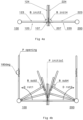
- Figs. 2a-b shows a cross section along the line A in Fig. 1a of the apparatus 800 and illustrate the movement of the first 100 and second 200 cuff opening assemblies from an initial position P initial to an opening position P opening .
- a first arm 110 and a second arm 120 of the first cuff opening assembly 100, and a first arm 210 and a second arm 220 of the second cuff opening assembly 200 all move relative to each other.
- the first arms 110, 210 of the first 100 and second 200 cuff opening assemblies respectively, comprises a first proximal end 111, 211 and a first distal end 112, 212, and is rotatable around a first geometrical shaft axis GA1, as illustrated in Figs.
- the second arm 120, 220 of the first 100 and second 200 cuff opening assemblies comprises a second proximal end 121, 221 and a second distal end 122, 222, and is rotatable around a second geometrical axis GA2.
- Figs. 2a-b shows a cross section of a part of the apparatus 800, only the first 112, 212 and the second 122, 222 distal ends of the first 100 and second 200 cuff opening assemblies, respectively, are shown in these figures.
- the other parts of the first 100 and second 200 cuff opening assemblies are shown in Figs. 3a-d and 4a-b , as mentioned above.
- the first 110, 210 and second 120, 220 arms are arranged to rotate around the first GA1 and second GA2 geometrical axes, respectively, between the initial position P initial and the opening position P opening .
- Fig. 2a shows the positions of the first 112, 212 and second 122, 222 distal ends relative to each other and relative to an opening of a glove 52 in the donning position P donning , when the first 110, 210 and second 120, 220 arms are in the initial position P initial .
- the first 112, 212 and second 122, 222 distal ends are at a first initial distance D initial1 from each other in the initial position P initial .
- first 112 and the second 122 distal ends of the first 110 and second 120 arms of the first cuff opening assembly 100 are at a second initial distance D initial2 from the first 212 and the second 222 distal ends of the first 210 and second 220 arms of the second cuff opening assembly 200, respectively, in the initial position P initial .
- the first initial distance D initial1 and the second initial distance D initial2 are arranged to be small, e.g. close to zero, such that the first 112, 212 and second 122, 222 distal ends are close together in the initial position P initial .
- Fig. 2a which also shows an initial area A initial and an area of an opening of the garment A g in its relaxed state.
- the initial area A initial is defined by the first 112 and second 122 distal ends of the first 110 and second 120 arms of the first cuff opening assembly 100 and the first 212 and second 222 distal ends of the first 210 and second 220 arms of the second cuff opening assembly 200, in the initial position P initial .
- the initial area A initial is smaller than the area of the opening of the glove A g in its relaxed state.
- first 112, 212 and second 122, 222 distal ends are separated from each other.
- the separation caused by the rotation takes place both horizontally and vertically, i.e. the first distal ends 112, 212 move away from the second distal ends 122, 222 of each one of the first 100 and second 200 cuff opening assembly, respectively, at the same time as the first 112 and second 122 distal ends of the first cuff opening assembly 100 move away from the first 212 and second 222 distal ends of the second cuff opening assembly 200, as indicated by the arrows in Fig.
- first 112, 212 and second 122, 222 distal ends may be inserted into the cuff of the glove 52 placed in the donning position P donning when the first 110, 210 and second 120, 220 arms are rotated around the first GA1 and second GA2 geometrical axes, respectively, from the initial position P initial to the opening position P opening .
- the first 112, 212 and second 122, 222 distal ends are separated from each other inside the glove 52 and starts to expand the cuff of the glove 52 during the rotation.
- FIG. 2b shows the positions of the first 112, 212 and second 122, 222 distal ends relative to each other, when the first 110, 210 and second 120, 220 arms are in the opening position P opening .
- the first 112, 212 and second 122, 222 distal ends of each one of the first 100 and second 200 cuff opening assembly, respectively, have been separated to a first opening distance D opening1 from each other in the opening position P opening .
- the first opening distance D opening1 is arranged to be greater than the first initial distance D initial1 .
- the first 112 and second 122 distal ends of the first 110 and second 120 arms of the first cuff opening assembly 100 are at a second opening distance D opening2 from the first 212 and second 222 distal ends of the first 210 and second 220 arms of the second cuff opening assembly 200, respectively, in the opening position P opening .
- the second opening distance D opening2 is arranged to be greater than the second initial distance D initial2 .
- the first opening distance D opening1 and the second opening distance D opening2 are arranged to be large enough to expand the cuff of the glove 52 in the donning position P donning .
- the first 112 and second 222 distal ends of the first 110 and second 120 arms of the first cuff opening assembly 100 and the first 212 and second 222 distal ends of the first 210 and second 220 arms of the second cuff opening assembly 200 in the opening position P opening defines an opening area A opening , where the opening area A opening is greater than the area of the opening of the glove Ag in its relaxed state, shown in Fig. 2a .
- the first 112, 212 and second 122, 222 distal ends are separated from each other when the first 110, 210 and second 120, 220 arms are rotated around the first GA1 and second GA2 geometrical axes, respectively, from the initial position P initial towards the opening position P opening .
- the separation of the first 112, 212 and second 122, 222 distal ends during the rotation is achieved by arranging the first GA1 and second GA2 geometrical axes with an angle ⁇ to each other, i.e. the first GA1 and second GA2 geometrical axes have an angle ⁇ relative to each other.
- the angle ⁇ is selected to be different/other than 0 or 180 degrees, such that the first GA1 and second GA2 geometrical axes do not have the same orientation.
- the first GA1 and second GA2 geometrical axes are oblique, i.e. non-parallel, to each other.
- the orientation of the first geometrical axis GA1 thus differs from the orientation of the second geometrical axis GA2, such that the first GA1 and second GA2 geometrical axes intersect, as shown e.g. in Figs. 2c-d .
- Figs. 2c-d show embodiments for a first cuff opening assembly 100.
- the first cuff opening assembly 100 is shown in the initial position P initial , in two different side views and in a top view.
- the first cuff opening assembly 100 is shown in the opening position P opening , in two different side views and in a top view.
- the first GA1 and second GA2 geometrical axes are arranged with an angle ⁇ to each other.
- the angle ⁇ is selected such that the first 112 and second 122 distal ends of the first cuff opening assembly 100 are at the first initial distance D initial1 from each other in the initial position P initial , as shown in Fig. 2c .
- the angle ⁇ is further selected such that the first 112 and second 122 distal ends of the first cuff opening assembly 100 are separated to the first opening distance D opening1 from each other in the opening position P opening , as shown in Fig. 2d , when the first 110 and second 120 arms are rotated around the first GA1 and second GA2 geometrical axes, respectively.
- first GA1 and second GA2 geometrical axes around which the first 210 and second 220 arms of the second cuff opening assembly 200 rotates may be arranged to each other with an angle ⁇ , where the angle ⁇ is selected such that the first 212 and second 222 distal ends of the second cuff opening assembly 200 are at the first initial distance D initial1 from each other in the initial position P initial , and are separated to the first opening distance D opening1 from each other in the opening position P opening (not shown in Figs.).
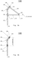
- Fig. 3a and 3b shows an embodiment where the rotation of the first 110 and second 120 arms of the first cuff opening assembly 100 takes place around a first 101 and a second 102 shaft, respectively.
- the first shaft 101 extends along the first geometrical axis GA1, while the second shaft 102 extends along the geometrical axis GA2.
- the first 101 and second 102 shafts are fixed in relation to each other, and possibly also in relation to the apparatus 800.
- the first arm 110 is arranged to rotate around the first shaft 101 extending along the first geometrical axis GA1 and the second arm 120 is arranged to rotate around the second shaft 102 extending along the geometrical axis GA2.
- the first arm 110 is rotatably attached to the first shaft 101 with a first attachment means 104
- the second arm 120 is rotatably attached to the second shaft 102 with a second attachment means 106.
- the first 104 and second 106 attachment means may include e.g. a tubular sleeve or a similar arrangement.
- the rotation of the first 110 and second 120 arms of the first cuff opening assembly 100 is also based on a first 101 shaft extending along the first geometrical axis GA1 and a second shaft 102 extending along the geometrical axis GA2.
- the first 101 and second 102 shafts are instead arranged to rotate around their own axis, while maintaining the angle ⁇ relative to each other.
- the first arm 110 is arranged to rotate together with the rotatable first shaft 101 extending along the first geometrical axis GA1 and being rotatable around the first geometrical axis GA1.
- the second arm 120 is arranged to rotate together with a rotatable second shaft 102 extending along the second geometrical axis GA2 and being rotatable around the second geometrical axis GA2.
- the first 101 and second 102 shafts may e.g. be attached to each other with a suitable coupling, which may include at least one gearwheel/cogwheel, e.g. a cardan/universal/gear joint.
- a suitable coupling which may include at least one gearwheel/cogwheel, e.g. a cardan/universal/gear joint.
- the rotation of the first 210 and second 220 arms of the second cuff opening assembly 200 may be achieved in the same way as for the embodiment shown in Figs. 3a-b or as for the embodiment shown in Figs. 3c-d for the first cuff opening assembly 100.
- the first 110, 210 and second 120, 220 arms of the first 100 and second 200 cuff opening assemblies may comprise parts which can move or rotate relative to the glove 52.
- the first 110, 210 and second 120, 220 arms may hence comprise an inner part and an outer part, where the outer part may be arranged to rotate around the inner part. In this way, the friction between the first 110, 210 and second 120, 220 arms and the glove 52 may be adjusted to match the properties of the glove 52, e.g. the friction may be reduced.
- the first arm 110 comprises an inner part 106 and an outer part 108.
- the outer part 108 is arranged to rotate around the inner part 106, e.g. by use of bearings.
- the outer part 108 of the first arm 110 may rotate relative to the glove 52, thereby reducing the rotational friction between the first arm 110 and the glove 52.
- the material of the outer part 108 may be selected such that a suitable longitudinal friction is achieved between the glove 52 and the first 110, 210 and second 120, 220 arms.
- the surface structure of the outer part 108 may be formed such that a suitable longitudinal friction is achieved between the glove 52 and the outer part 108.
- the outer part 108 may comprise grooves or notches for engaging with the cuff of the glove 52. In this way, the risk of the glove 52 slipping of the first 110, 210 and second 120, 220 arms during the expansion of the glove 52 or when the hand is inserted into the glove 52 is reduced.
- the grooves are illustrated as comprising four equally distanced v-shaped grooves arranged around the outer part 108.
- any number or shape of grooves may be used without deviating from the scope of the invention.
- the material and/or the surface structure of the outer part 108 may be selected such that a suitable longitudinal friction is achieved between the glove 52 and the outer part 108.
- the material and/or the surface structure of the first 110, 210 and second 120, 220 arms in embodiments where the first 110, 210 and second 120, 220 arms do not comprise an outer part 108 may also be selected such that a suitable longitudinal friction is achieved between the glove 52 and the outer part 108.
- air may be blown into the glove 52 when it has been expanded, to further facilitate the donning of the glove 52.
- the air may e.g. be provided from an air supply through a nozzle which may be external or integrated into the first 100 and second 200 cuff opening assemblies.
- the air may e.g. be supplied through the first 110, 210 and second 120, 220 arms of the first 100 and second 200 cuff opening assemblies.
- Fig. 3e shows such an embodiment for the first arm 110 of the first 100 cuff opening assembly.
- the same principles apply to any one of the arms 110, 120, 210, 220. In the embodiment shown in Fig.
- the first arm 110 is hollow and air may be blown through the first arm 110 and out through the first distal end 112. In this way, the first arm 110 may e.g. blow air into the glove 52 in the expanded state, thereby inflating the glove 52 such that the donning of the glove 52 is facilitated.
- Alternative ways of implementing the separation of the first 112, 212 and second 122, 222 distal ends when the first 110, 210 and second 120, 220 arms are rotated around the first GA1 and second GA2 geometrical axes, respectively, may e.g. be based on a groove in the first 101, 201 and/or second 102, 202 shafts or a thread arranged to guide the rotation of the first 110, 210 and second 120, 220 arms.
- the first 101, 201 and second 102, 202 shafts may be aligned, and the groove may be fixed in relation to at least one of the first 101, 201 and second 102, 202 shafts.
- At least one of the first 110, 210 and second 120, 220 arms is then guided by the groove in its rotation, such that the first 112, 212 and second 122, 222 distal ends are at the first initial distance D init1 from each other in the initial position P initial , and are separated to the first opening distance D opening1 from each other in the opening position P opening , when the first 110, 210 and second 120, 220 arms are rotated around the first 101, 201 and second 102, 202 shafts, respectively.
- the first 101, 201 and second 102, 202 shafts may be aligned and at least one of the first 101, 201 and second 102, 202 shafts may comprise a thread.
- At least one of the first 110, 210 and second 120, 220 arms is guided by the thread in its rotation, such that the first 112, 212 and second 122, 222 distal ends are at the first initial distance D init1 from each other in the initial position P initial , and are separated to the first opening distance D opening1 from each other in the opening position P opening , when the first 110, 210 and second 120, 220 arms are rotated around the first 101, 201 and second 102, 202 shafts, respectively.
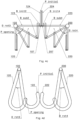
- each of the first arms 110, 210 and the second arms 120, 220 of the first 100 and second 200 cuff opening assemblies comprise two parts resiliently connected and arranged at an angle to each other.
- the first arm 110, 210 comprises a first proximal part 113, 213 and a first distal part 114, 214 resiliently connected to each other.
- the second arm 120, 220 comprises a second proximal part 123, 223 and a second distal part 124, 224 resiliently connected to each other.
- the first 113, 213 and the second 123, 223 proximal parts may e.g. be resiliently connected to the first 114, 214 and the second 124, 224 distal parts, respectively, by means of at least one spring joint or a resilient material of the first 110, 210 and second 120, 220 arms.
- Figs. 4a-b show a top view of a first 100 and a second 200 cuff opening assembly where the first 110, 210 and second 120, 220 arms of the first 100 and second 200 cuff opening assemblies, respectively, comprise two resiliently connected parts.
- Figs. 4a-b shows a top view only the second arms 120, 220 of the first 100 and second 200 cuff opening assemblies, respectively, are visible.
- the second arm 120 of the first cuff opening assembly 100 comprises a second proximal part 123 and a second distal part 124 resiliently connected with a spring joint 107.
- the second arm 220 of the second cuff opening assembly 200 comprises a second proximal part 223 and a second distal part 224 resiliently connected with a spring joint 207.
- the first 110, 210 arms of the first 100 and second 200 cuff opening assemblies are in a similar way comprising a first proximal part 113, 213 and a first distal part 114, 214 resiliently connected to each other, e.g. with spring joints.
- Figs. 4a the second arms 120, 220 of the first 100 and second 200 cuff opening assemblies, respectively, are shown in the initial position P initial .
- the first 114 and second 124 distal parts of the first cuff opening assembly 100 may be in contact with the first 214 and second 224 distal parts of the second cuff opening assembly 200, respectively.
- first distal part 114 of the first cuff opening assembly 100 are at a first initial angle ⁇ init1 to the first proximal part 113 of the first cuff opening assembly 100
- first distal part 214 of the second cuff opening assembly 200 are at a third initial angle ⁇ init3 to the first proximal part 213 of the second cuff opening assembly 200 (not shown in the Figs.).
- the second distal part 124 of the first cuff opening assembly 100 are at a second initial angle ⁇ init2 to the second proximal part 123 of the first cuff opening assembly 100
- the second distal part 224 of the second cuff opening assembly 200 are at a fourth initial angle ⁇ init4 to the second proximal part 223 of the second cuff opening assembly 200, as shown in Fig. 4a .
- the length of the second distal parts 124, 224 and the second proximal part 123, 223 are selected such that the second distal part 124 of the first cuff opening assembly 100 and the second distal part 224 of the second cuff opening assembly 200 are parallel to each other and in contact with each other in the initial position P initial .
- the second initial angle ⁇ init2 and the fourth initial angle ⁇ init4 is approximately 90 degrees in the initial position P initial , as shown in Fig. 4a .
- the length of the first distal parts 114, 214 and the first proximal part 113, 213 are selected such that the first distal part 114 of the first cuff opening assembly 100 and the first distal part 214 of the second cuff opening assembly 200 are parallel to each other and in contact with each other in the initial position P initial .
- the first initial angle ⁇ init1 and the third initial angle ⁇ init3 is approximately 90 degrees in the initial position P initial (not shown in Figs.) .
- first 110, 210 and second 120, 220 arms rotate around the first GA1 and second GA2 geometrical axes, respectively, the first 114 and second 124 distal parts of the first cuff opening assembly 100 will move away from the first 214 and second 224 distal parts of the second cuff opening assembly 200, leaving room for each distal part to move relative to the proximal part it is connected to. Due to the resilient connection between each distal and proximal part, the rotation may hence lead to that the angle ⁇ between the distal parts and the proximal parts changes, typically increases.
- the first 114, 214 and second 124, 224 distal parts of the first 100 and second 200 cuff opening assemblies meet an inside of the cuff of the glove 52 and starts to expand the cuff of the glove 52.
- the resistance from the glove 52 leads to a force on the first 114, 214 and second 124, 224 distal parts of the first 100 and second 200 cuff opening assemblies, which will further increase the angle ⁇ between the distal parts and the proximal parts.
- Fig. 4b shows the second arms 120, 220 of the first 100 and second 200 cuff opening assemblies, respectively, in different subsequent position as the second arms 120, 220 of the first 100 and second 200 cuff opening assemblies rotate away from the initial position P initial towards the opening position P opening .
- the angle ⁇ between the second distal part 124 and the second proximal part 123 of the first cuff opening assembly 100 increases when the second arm 120 of the first cuff opening assembly 100 rotates away from the initial position P initial .
- the angle ⁇ between the second distal part 224 and the second proximal part 223 of the second cuff opening assembly 200 increases when the second arm 220 of the second cuff opening assembly 200 rotates away from the initial position P initial .
- the angle ⁇ between the second distal part 124 and the second proximal part 123 of the second arm 120 of the first cuff opening assembly 100 in a subsequent position is herein denoted a second subsequent angle ⁇ sub2
- the angle ⁇ between the second distal part 224 and the second proximal part 223 of the second arm 220 of the second cuff opening assembly 200 in a subsequent position is herein denoted a fourth subsequent angle ⁇ sub4 , as shown in Fig. 4b .
- Corresponding subsequent angles for the first arms 110, 210 of the first 100 and second 200 cuff opening assemblies are denoted a first subsequent angle ⁇ sub1 and a third subsequent angle ⁇ sub3 , respectively.
- the second subsequent angle ⁇ sub2 and the fourth subsequent angle ⁇ sub4 may be approximately 180 degrees, as shown in Fig. 4b .
- Fig. 4b shows the subsequent position for the second arms 120, 220 of the first 100 and second 200 cuff opening assemblies as they rotate towards the opening position P opening .
- first arms 110, 210 of the first 100 and second 200 cuff opening assemblies behaves in a similar way.
- the first 114, 214 and second 124, 224 distal parts of the first 100 and second 200 cuff opening assemblies are in contact with an inside of the cuff of the glove 52, such that the first distal part 114 of the first cuff opening assembly 100 is at a first subsequent angle ⁇ sub1 to the first proximal part 113 of the first cuff opening assembly 100, the second distal part 124 of the first cuff opening assembly 100 is at a second subsequent angle ⁇ sub2 to the second proximal part 123 of the first cuff opening assembly 100, the first distal part 214 of the second cuff opening assembly 200 are at a third subsequent angle ⁇ sub3 to the first proximal part 213 of the second cuff opening assembly 200, and the second distal part 224 of the second cuff opening assembly 200 are at a fourth subsequent angle ⁇ sub4 to the second proximal part 223 of the second cuff opening assembly 200.
- the first subsequent angle ⁇ sub1 is greater than the first initial angle ⁇ init1
- the second subsequent angle ⁇ sub2 is greater than the second initial angle ⁇ init2
- the third subsequent angle ⁇ sub3 is greater than the third initial angle ⁇ init3
- the fourth subsequent angle ⁇ sub4 is greater than the fourth initial angle ⁇ init4 .
- the first subsequent angle ⁇ sub1 , the second subsequent angle ⁇ sub2 , the third subsequent angle ⁇ sub3 , and the fourth subsequent angle ⁇ sub4 are approximately 180 degrees.
- the first 110 and second 120 arms of the first cuff opening assembly 100 rotates in a first rotation direction D rot1
- the first 210 and second 220 arms of the second cuff opening assembly 200 rotates in a second rotation direction D rot2 , when moving from the initial position P initial to the opening position P opening .
- the second rotation direction D rot2 is opposite to the first rotation direction D rot1 .
- the first 110, 210 and second 120, 220 arms of the first 100 and second 200 cuff opening assemblies may instead rotate in opposite directions to the first D rot1 and the second D rot2 rotation direction, respectively.
- Figs. 4c-d show examples of such embodiments.
- the first 110 and second 120 arms of the first cuff opening assembly 100 rotates in a third rotation direction D rot3
- the first 210 and second 220 arms of the second cuff opening assembly 200 rotates in a fourth rotation direction D rot4
- the fourth rotation direction D rot4 is opposite to the third rotation direction D rot3 .
- the first 114, 214 and second 124, 224 distal parts of the first 100 and second 200 cuff opening assemblies are linked to the first 113, 213 and second 123, 223 proximal parts of the first 100 and second 200 cuff opening assemblies, respectively, such that the first 114, 214 and second 124, 224 distal parts of the first 100 and second 200 cuff opening assemblies maintains their direction relative to the glove 52, when the first 110, 210 and second 120, 220 arms of the first 100 and second 200 cuff opening assemblies rotates to open the glove 52.
- the linkage between the first 114, 214 and second 124, 224 distal parts of the first 100 and second 200 cuff opening assemblies and the first 113, 213 and second 123, 223 proximal parts of the first 100 and second 200 cuff opening assemblies can e.g. comprise a chain or other known means. Due to the linkage, the first subsequent angle ⁇ sub1 , the second subsequent angle ⁇ sub2 , the third subsequent angle ⁇ sub3 , and the fourth subsequent angle ⁇ sub4 decreases as the first 110, 210 and second 120, 220 arms of the first 100 and second 200 cuff opening assemblies rotates towards the opening position P opening , as shown in Fig. 4c for the second subsequent angle ⁇ sub2 and the fourth subsequent angle ⁇ sub4 .
- the first subsequent angle ⁇ sub1 , the second subsequent angle ⁇ sub2 , the third subsequent angle ⁇ sub3 , and the fourth subsequent angle ⁇ sub4 may be approximately 0 degrees.
- Fig. 4d shows a further embodiment where the first 110 and second 120 arms of the first cuff opening assembly 100 rotates in a third rotation direction D rot3 and the first 210 and second 220 arms of the second cuff opening assembly 200 rotates in a fourth rotation direction D rot4 , when moving from the initial position P initial to the opening position P opening .
- the first 110, 210 and second 120, 220 arms of the first 100 and second 200 cuff opening assemblies are curve shaped, i.e.
- first 110, 210 and second 120, 220 arms of the first 100 and second 200 cuff opening assemblies rotates from the initial position P initial towards the opening position P opening , the distal ends 112, 122, 122, 222 of the first 100 and second 200 cuff opening assemblies are separated from each other such that the glove 52 is opened.
- FIG. 4d shows a top view only the second arms 120, 220 of the first 100 and second 200 cuff opening assemblies, respectively, are visible.
- Fig. 4d shows how the second distal end 122 of the second arm 120 of the first cuff opening assembly 100 is separated from the second distal end 222 of the second arm 220 of the second cuff opening assembly 200, when the second arm 120 of the first cuff opening assembly 100 rotates in the third rotation direction D rot3 and the second arm 220 of the second cuff opening assembly 200 in the fourth rotation direction D rot4 .
- the length and the shape of the first 110, 210 and second 120, 220 arms of the first 100 and second 200 cuff opening assemblies are selected such that when the first 110, 210 and second 120, 220 arms of the first 100 and second 200 cuff opening assemblies reaches the opening position P opening the gloves 52 is opened to the extent that the user can easily insert his or her hands into the glove 52.
- Figures 4a-d show a top view of the first 100 and second 200 cuff opening assemblies, therefore the first arms 110, 210 of the first 100 and second 200 cuff opening assemblies are not shown in these figures. However, as is understood by a skilled person, the first arms 110, 210 of the first 100 and second 200 cuff opening assemblies, respectively, are also rotated in a corresponding way as illustrated for the second arms 120, 220 in figures 4a-d , and described above.
- the first 110, 210 and second 120, 220 arms of the first 100 and second 200 cuff opening assemblies, respectively, may be coupled with a first coupling means such that the first 110, 210 and second 120, 220 arms rotates synchronously around the first GA1 and second GA2 geometrical axes, respectively.
- the first 110 and second 120 arms of the first cuff opening assembly 100 may be coupled such that the first 110 and second 120 arms rotate together, i.e. at the same time and in the same rotation direction, around or together with the first 101 and second 102 shafts, respectively.
- the first subsequent angle ⁇ sub1 is in this case typically essentially equal to the second subsequent angle ⁇ sub2 .
- first 210 and second 220 arms of the second cuff opening assembly may be coupled such that the first 210 and second 220 arms rotates together, i.e. at the same time and in the same rotation direction, around or together with the first 201 and second 202 shafts, respectively.
- the third subsequent angle ⁇ sub3 is in this case typically essentially equal to the fourth subsequent angle ⁇ sub4 .
- first 110 and second 120 arms of the first cuff opening assembly 100 may be coupled to at least one of the first 210 and second 220 arms of the second cuff opening assembly 200 with a second coupling means, such that the first 110, 210 and second 120, 220 arms of the first 100 and second 200 cuff opening assemblies rotate synchronously around their respective geometrical axes GA2, GA2.
- first subsequent angle ⁇ sub1 , the second subsequent angle ⁇ sub2 , the third subsequent angle ⁇ sub3 , and the fourth subsequent angle ⁇ sub4 are typically essentially equal.
- the first 110 and second 120 arms of the first cuff opening assembly 100 may rotate in the first rotation direction D rot1
- the first 210 and second 220 arms of the second cuff opening assembly 200 may rotate in the second rotation direction D rot2 , where the second rotation direction D rot2 is opposite to the first rotation direction D rot1 .
- At least one cuff opening arrangement 600, 700 further comprises at least one rotation providing means coupled to at least one of the first 110, 210 and second 120, 220 arms of the first 100 and second 200 cuff opening assemblies.
- the rotation providing means may be arranged to cause the rotation of at least one of the first 110, 210 and second 120, 220 arms of the first 100 and second 200 cuff opening assemblies between the initial position P initial and the opening position P opening .
- the rotation providing means may comprises at least one rod 510, 520 coupled to at least one of the first 110, 210 and second 120, 220 arms of the first 100 and second 200 cuff opening assemblies.
- the at least one rod 510, 520 is in a first position the first 110, 210 and second 120, 220 arms of the first 100 and second 200 cuff opening assemblies are in the initial position P initial .
- the at least one rod 510, 520 is in a second position, the first 110, 210 and second 120, 220 arms of the first 100 and second 200 cuff opening assemblies are in the opening position P opening .
- the displacement of the at least one rod 510, 520 may be provided with a displacement means 540.
- the at least one rotation providing means may comprise at least one displacement means 540 coupled to the at least one rod 510, 520 and arranged to displace the at least one rod 510, 520 between the first and second positions.
- the at least one rod 510 of the first cuff opening arrangement 600 may be coupled to the at least one rod 520 of the second cuff opening arrangement 700.
- the rotation providing means may comprise a displacement means 540 coupled to one or more of the at least one rod 510, 520 of the first 600 or second 700 cuff opening arrangements, and arranged to displace the at least one rod 510, 520 of the first 600 and second 700 cuff opening arrangements, respectively, between the first and second positions
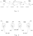
- Fig. 5 shows a rotation providing means according to an embodiment of the invention.
- a first 600 and a second 700 cuff opening arrangement is shown.
- a rod 510 is coupled to a first 100 and a second 200 cuff opening assembly of the first cuff opening arrangement 600
- a rod 520 is coupled to a third 300 and a fourth 400 cuff opening assembly of the second cuff opening arrangement 700.
- the rod 510 of the first cuff opening arrangement 600 is coupled to the rod 520 of the second cuff opening arrangement 700 with a coupling rod 530.
- the rotation providing means comprises a displacement means 540 attached to the coupling rod 530 and the rod 520 of the second cuff opening arrangement 700.
- the displacement means 540 is arranged to displace the rods 510, 520 of the first 600 and second 700 cuff opening arrangements, respectively, between the first and second positions.
- the displacement means 540 is a piston coupled to the rods 510, 520, 530 which displaces the rods 510, 520 of the first 600 and second 700 cuff opening arrangements by extracting and retracting the piston.
- the displacement means 540 may instead be another type of known displacement means.
- the rotation of the first 110, 210 and second 120, 220 arms of the first 100 and second 200 cuff opening assemblies around the first GA1 and second GA2 geometrical axes may alternatively be provided using rotary engines.
- the at least one rotation providing means may comprise at least one rotary engine 551, 552 coupled to at least one of the first 110, 210 and second 120, 220 arms of the first 100 and second 200 cuff opening assemblies.
- the at least one rotary engine 551, 552 may be arranged to rotate the first 110, 210 and second 120, 220 arms of the first 100 and second 200 cuff opening assemblies from the initial position P initial to the opening position P opening .
- the rotary engines 551, 552 may further be synchronized such that the first 110, 210 and second 120, 220 arms of the first 100 and second 200 cuff opening assemblies rotate synchronously around their respective geometrical axes GA1, GA2.
- Fig. 6 shows an embodiment of the invention where the rotation providing means comprises at least one rotary engine.
- Fig. 5 shows a first 600 and a second 700 cuff opening arrangement, where the first cuff opening arrangement 600 comprises a first 100 and a second 200 cuff opening assembly, and the second cuff opening arrangement 700 comprises a third 300 and a fourth 400 cuff opening assembly.
- the rotation of the first 100, second 200, third 300, and fourth 400 cuff opening assemblies are provided with a first 551, a second 552, a third 552, and a fourth 554 rotary engine.
- Each rotary engine 551, 552, 553, 554 is coupled to at least one of the first 110, 210 and second 120, 220 arms of one cuff opening assembly 100, 200, 300, 400, as shown in Fig. 6 .
- the rotary engines 551, 552, 553, 554 are arranged to rotate the first 110, 210 and second 120, 220 arms of the first 100 and second 200 cuff opening assemblies, as well as the first 110, 210 and second 120, 220 arms of the third 300 and fourth 400 cuff opening assemblies, from the initial position P initial to the opening position P opening .
- the rotary engines 551, 552, 553, 554 may further be synchronized such that the first 110, 210 and second 120, 220 arms of first 100, second 200, third 300, and fourth 400 cuff opening assemblies rotate synchronously around their respective geometrical axes GA1, GA2.
- the rotary engines 551, 552, 553, 554 may e.g. be pneumatic engines or electrical engines.
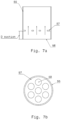
- the garment fetching arrangement 50 of the apparatus 800 may utilizes suction for fetching a glove 52 from a glove storage 54 and placing the glove 52 in a donning position P donning . Further details related to a garment fetching arrangement 50 utilizing suction is described below with reference to Figs. 7a-b.
- Fig. 7a shows a cross section of an end section 55 of a garment fetching arrangement 50 according to an embodiment of the invention.
- the Fig. 7b shows a bottom view of the end section 55 of the garment fetching arrangement 50.
- the garment fetching arrangement 50 may comprise two end sections 55.
- a first 55a and a second 55b end section as shown in Fig. 1b .
- each end section 55a, 55b may be arranged as shown in Figs. 7a-b .
- the garment fetching arrangement 50 may be arranged to suck in air through the end section 55 such that when the end section 55 is positioned close to a glove 52 suction is created between the end section 55 and the glove 52.
- the glove 52 is thereby attached to the end section 55 and the garment fetching arrangement 50 can lift and move the glove 52 to the donning position P donning .
- the garment fetching arrangement 50 should only attach to one side of the glove 52, leaving the other side of the glove 52 unattached, such that the glove 52 is opened when the garment fetching arrangement 50 lifts the glove 52 from the glove storage 54.
- the end section 55 includes a disc 57, which comprises one or more holes 58 through which air can flow, as shown in Fig. 7b .
- the disc 57 may be arranged inside the end section 55 at a distance D suction from an end 56 of the end section 55, as shown in Fig. 7a .
Landscapes
- Health & Medical Sciences (AREA)
- Surgery (AREA)
- Life Sciences & Earth Sciences (AREA)
- Medical Informatics (AREA)
- Biomedical Technology (AREA)
- Heart & Thoracic Surgery (AREA)
- Engineering & Computer Science (AREA)
- Molecular Biology (AREA)
- Animal Behavior & Ethology (AREA)
- General Health & Medical Sciences (AREA)
- Public Health (AREA)
- Veterinary Medicine (AREA)
- Professional, Industrial, Or Sporting Protective Garments (AREA)
- Measuring Pulse, Heart Rate, Blood Pressure Or Blood Flow (AREA)
- Holders For Apparel And Elements Relating To Apparel (AREA)
Claims (15)
- Einrichtung (800), die zum Erleichtern eines Anlegens eines Kleidungsstücks (52), das einen Bund umfasst, an einen Teil eines menschlichen Körpers angeordnet ist;wobei die Einrichtung (800) Folgendes umfasst:- eine Kleidungsstückholanordnung (50), die zum Holen eines Kleidungsstücks (52) aus einem Kleidungsstücklager (54) und Platzieren des Kleidungsstücks in einer Anlegeposition (Pdonning) angeordnet ist;- mindestens eine Bundöffnungsanordnung (600, 700), die dazu angeordnet ist, einen Bund des Kleidungsstücks (52) in der Anlegeposition (Pdonning) zu öffnen, und die eine erste (100) und eine zweite (200) Bundöffnungsbaugruppe umfasst, wobei jede der ersten (100) und zweiten (200) Bundöffnungsbaugruppen Folgendes umfasst:- einen ersten Arm (110, 210), der ein erstes proximales Ende (111, 211) und ein erstes distales Ende (112, 212) umfasst, wobei der erste Arm (110, 210) um eine erste geometrische Achse (GA1) drehbar ist;- einen zweiten Arm (120, 220), der ein zweites proximales Ende (121, 221) und ein zweites distales Ende (122, 222) umfasst, wobei der zweite Arm (120, 220) um eine zweite geometrische Achse (GA2) drehbar ist; wobei- die ersten (110, 210) und zweiten (120, 220) Arme dazu angeordnet sind, sich um die ersten (GA1) bzw. zweiten (GA2) geometrischen Achsen zwischen einer anfänglichen Position (Pinitial) und einer Öffnungsposition (Popening) zu drehen, und wobei die ersten (GA1) und zweiten (GA2) geometrischen Achsen mit einem relativen Winkel α zueinander angeordnet sind, wobei die ersten (112, 212) und zweiten (122, 222) distalen Enden so angeordnet sind, um Folgendes zu sein:- in einem ersten anfänglichen Abstand Dinitial1 voneinander in der anfänglichen Position (Pinitial); und- getrennt zu einem ersten Öffnungsabstand Dopening1 voneinander in der Öffnungsposition (Popening), wobei der erste Öffnungsabstand Dopening1 größer als der erste anfängliche Abstand Dinitial1 ist,dadurch gekennzeichnet, dassder relative Winkel α derart ausgewählt ist, dass die ersten (GA1) und zweiten (GA2) geometrischen Achsen unterschiedliche Orientierungen aufweisen,wobei die Trennung durch die Drehung der ersten (110, 210) und zweiten (120, 220) Arme in den unterschiedlichen Orientierungen um die ersten (GA1) bzw. zweiten (GA2) geometrischen Achsen erzielt wird.
- Einrichtung nach Anspruch 1, wobei:- der erste Arm (110, 210) dazu angeordnet ist, sich um eine erste Welle (101, 201) zu drehen, die sich entlang der ersten geometrischen Achse (GA1) erstreckt; und- der zweite Arm (120, 220) dazu angeordnet ist, sich um eine zweite Welle (102, 202) zu drehen, die sich entlang der geometrischen Achse (GA2) erstreckt.
- Einrichtung nach Anspruch 1, wobei:- der erste Arm (110, 210) dazu angeordnet ist, sich zusammen mit einer drehbaren ersten Welle (101, 201) zu drehen, die sich entlang der ersten geometrischen Achse (GA1) erstreckt und um die erste geometrische Achse (GA1) drehbar ist; und- der zweite Arm (120, 220) dazu angeordnet ist, sich zusammen mit einer drehbaren zweiten Welle (102, 202) zu drehen, die sich entlang der zweiten geometrischen Achse (GA2) erstreckt und um die zweite geometrische Achse (GA2) drehbar ist.
- Einrichtung (800) nach einem der vorhergehenden Ansprüche, wobei die ersten (112, 212) und zweiten (122, 222) distalen Enden in einen Bund eines Kleidungsstücks (52) eingesetzt werden, das in der Anlegeposition (Pdonning) platziert ist, wenn die ersten (110, 210) und zweiten (120, 220) Arme um die ersten (GA1) bzw. zweiten (GA2) geometrischen Achsen von der anfänglichen Position (Pinitial) zu der Öffnungsposition (Popening) gedreht werden.
- Einrichtung (800) nach einem der vorhergehenden Ansprüche, wobei- sich ein erstes (112) und ein zweites (122) distales Ende der ersten (110) und zweiten (120) Arme der ersten Bundöffnungsbaugruppe (100) in einem zweiten anfänglichen Abstand Dinitial2 von einem ersten (212) und einem zweiten (222) distalen Ende der ersten (210) bzw. zweiten (220) Arme der zweiten Bundöffnungsbaugruppe (200) in der anfänglichen Position (Pinitial) befinden;- sich die ersten (112) und zweiten (122) distalen Enden der ersten Bundöffnungsbaugruppe (100) in einem zweiten Öffnungsabstand Dopening2 von den ersten (212) bzw. zweiten (222) distalen Enden der zweiten Bundöffnungsbaugruppe () in der Öffnungsposition (Popening) befinden; und- der zweite Öffnungsabstand Dopening2 größer als der zweite anfängliche Abstand Dinitial2 ist.
- Einrichtung (800) nach einem der vorhergehenden Ansprüche, wobei- die ersten (112) und zweiten (122) distalen Enden der ersten (110) und zweiten (120) Arme der ersten Bundöffnungsbaugruppe (100) und die ersten (212) und zweiten (222) distalen Enden der ersten (210) und zweiten (220) Arme der zweiten Bundöffnungsbaugruppe (200) in der anfänglichen Position (Pinitial) einen anfänglichen Bereich Ainitial definieren; und- der anfängliche Bereich Ainitial kleiner als ein Bereich einer Öffnung des Kleidungsstücks Ag in seinem entspannten Zustand ist.
- Einrichtung (800) nach einem der vorhergehenden Ansprüche, wobei- die ersten (112) und zweiten (122) distalen Enden der ersten (110) und zweiten (120) Arme der ersten Bundöffnungsbaugruppe (100) und die ersten (212) und zweiten (222) distalen Enden der ersten (210) und zweiten (220) Arme der zweiten Bundöffnungsbaugruppe (200) in der Öffnungsposition (Popening) einen Öffnungsbereich Aopening definieren; und- der Öffnungsbereich Aopening größer als ein Bereich einer Öffnung des Kleidungsstücks Ag in seinem entspannten Zustand ist.
- Einrichtung (800) nach einem der vorhergehenden Ansprüche, wobei- die ersten (110, 210) und zweiten (120, 220) Arme der ersten (100) bzw. zweiten (200) Bundöffnungsbaugruppen mit einem ersten Kopplungsmittel derart gekoppelt sind, dass sich die ersten (110, 210) und zweiten (120, 220) Arme synchron um die ersten (GA1) bzw. zweiten (GA2) geometrischen Achsen drehen.
- Einrichtung (800) nach Anspruch 8, wobei- mindestens einer der ersten (110) und zweiten (120) Arme der ersten Bundöffnungsbaugruppe (100) mit mindestens einem der ersten (210) und zweiten (220) Arme der zweiten Bundöffnungsbaugruppe (200) mit einem zweiten Kopplungsmittel (530) derart gekoppelt ist, dass sich die ersten (110, 210) und zweiten (120, 220) Arme der ersten (100) und zweiten (200) Bundöffnungsbaugruppen synchron um ihre jeweiligen geometrischen Achsen (GA2, GA2) drehen; und- sich die ersten (110) und zweiten (120) Arme der ersten Bundöffnungsbaugruppe (100) in einer ersten Drehrichtung Drot1 drehen und sich die ersten (210) und zweiten (220) Arme der zweiten Bundöffnungsbaugruppe (200) in einer zweiten Drehrichtung Drot2 drehen, wobei die zweite Drehrichtung Drot2 entgegengesetzt zu der ersten Drehrichtung Drot1 ist.
- Einrichtung (800) nach einem der vorhergehenden Ansprüche, wobei die mindestens eine Bundöffnungsanordnung (600, 700) ferner Folgendes umfasst:- mindestens ein Drehungsbereitstellungsmittel, das mit mindestens einem der ersten (110, 210) und zweiten (120, 220) Arme der ersten (100) und zweiten (200) Bundöffnungsbaugruppen gekoppelt ist, das dazu angeordnet ist, die Drehung mindestens eines der ersten (110, 210) und zweiten (120, 220) Arme der ersten (100) und zweiten (200) Bundöffnungsbaugruppen zwischen der anfänglichen Position (Pinitial) und der Öffnungsposition (Popening) zu bewirken.
- Einrichtung (800) nach Anspruch 10, wobei das mindestens eine Drehungsbereitstellungsmittel Folgendes umfasst:- mindestens einen Stab (510, 520), der mit mindestens einem der ersten (110, 210) und zweiten (120, 220) Arme der ersten (100) und zweiten (200) Bundöffnungsbaugruppen gekoppelt ist; wobei- wenn sich der mindestens eine Stab (510, 520) in einer ersten Position befindet, sich die ersten (110, 210) und zweiten (120, 220) Arme der ersten (100) und zweiten (200) Bundöffnungsbaugruppen in der anfänglichen Position (Pinitial) befinden; und- wenn sich der mindestens eine Stab (510, 520) in einer zweiten Position befindet, sich die ersten (110, 210) und zweiten (120, 220) Arme der ersten (100) und zweiten (200) Bundöffnungsbaugruppen in der Öffnungsposition (Popening) befinden.
- Einrichtung (800) nach Anspruch 11, wobei das mindestens eine Drehungsbereitstellungsmittel Folgendes umfasst:- mindestens ein Verschiebungsmittel (540), das mit dem mindestens einen Stab (510, 520) gekoppelt und dazu angeordnet ist, den mindestens einen Stab (510, 520) zwischen den ersten und zweiten Positionen zu verschieben.
- Einrichtung (800) nach Anspruch 11, umfassend- eine erste Bundöffnungsanordnung (600) und eine zweite Bundöffnungsanordnung (700); wobei- mindestens ein Stab (510) der ersten Bundöffnungsanordnung (600) mit mindestens einem Stab (520) der zweiten Bundöffnungsanordnung (700) gekoppelt ist;- das mindestens eine Drehungsbereitstellungsmittel Folgendes umfasst:- ein Verschiebungsmittel (540), das mit einem oder mehreren des mindestens einen Stabs (510, 520) der ersten (600) oder zweiten (700) Bundöffnungsanordnungen gekoppelt und dazu angeordnet ist, den mindestens einen Stab (510, 520) der ersten (600) und zweiten (700) Bundöffnungsanordnungen zwischen den ersten bzw. zweiten Positionen zu verschieben.
- Einrichtung (800) nach Anspruch 10, wobei das mindestens eine Drehungsbereitstellungsmittel Folgendes umfasst:- mindestens einen Rotationsmotor (551, 552), der mit mindestens einem der ersten (110, 210) und zweiten (120, 220) Arme der ersten (100) und zweiten (200) Bundöffnungsbaugruppen gekoppelt ist; wobeider mindestens eine Rotationsmotor (551, 552) dazu angeordnet ist, die ersten (110, 210) und zweiten (120, 220) Arme der ersten (100) und zweiten (200) Bundöffnungsbaugruppen von der anfänglichen Position (Pinitial) zu der Öffnungsposition (Popening) zu drehen.
- Einrichtung (800) nach Anspruch 14, wobei das mindestens eine Drehungsbereitstellungsmittel Folgendes umfasst:- mindestens zwei Rotationsmotoren (551, 552), die derart synchronisiert sind, dass sich die ersten (110, 210) und zweiten (120, 220) Arme der ersten (100) und zweiten (200) Bundöffnungsbaugruppen synchron um ihre jeweiligen geometrischen Achsen (GA1, GA2) drehen.
Applications Claiming Priority (2)
| Application Number | Priority Date | Filing Date | Title |
|---|---|---|---|
| SE1850657A SE542664C2 (en) | 2018-05-31 | 2018-05-31 | Apparatus for facilitating donning a garment |
| PCT/SE2019/050445 WO2019231377A1 (en) | 2018-05-31 | 2019-05-16 | Apparatus for facilitating donning a garment |
Publications (4)
| Publication Number | Publication Date |
|---|---|
| EP3801352A1 EP3801352A1 (de) | 2021-04-14 |
| EP3801352A4 EP3801352A4 (de) | 2022-03-09 |
| EP3801352B1 true EP3801352B1 (de) | 2023-06-21 |
| EP3801352C0 EP3801352C0 (de) | 2023-06-21 |
Family
ID=68698888
Family Applications (1)
| Application Number | Title | Priority Date | Filing Date |
|---|---|---|---|
| EP19810690.8A Active EP3801352B1 (de) | 2018-05-31 | 2019-05-16 | Vorrichtung zur erleichterung des anziehens eines kleidungsstücks |
Country Status (6)
| Country | Link |
|---|---|
| US (1) | US11330925B2 (de) |
| EP (1) | EP3801352B1 (de) |
| JP (1) | JP2021525635A (de) |
| CN (1) | CN112203612A (de) |
| SE (1) | SE542664C2 (de) |
| WO (1) | WO2019231377A1 (de) |
Families Citing this family (7)
| Publication number | Priority date | Publication date | Assignee | Title |
|---|---|---|---|---|
| IL272406B (en) * | 2020-02-02 | 2020-07-30 | Matan Shalom Avshalom Shlomo | Apparatus for putting a glove on a palm hand |
| CN111407417B (zh) * | 2020-04-13 | 2021-02-19 | 邹伟伟 | 一种一次性手术手套病毒防护快速脱取装置 |
| WO2022040197A1 (en) * | 2020-08-18 | 2022-02-24 | Rsm Global Llc | Robotic glove donning machine |
| RU2746874C1 (ru) * | 2020-12-31 | 2021-04-21 | Александр Михайлович Белый | Аппарат для надевания одноразовых защитных перчаток |
| PL245027B1 (pl) * | 2021-06-23 | 2024-04-22 | Innova Good Spolka Z Ograniczona Odpowiedzialnoscia | Automat do wydawania rękawic |
| CA3228276A1 (en) * | 2021-06-23 | 2022-12-29 | "Innova Good" Spolka Z Ograniczona Odpowiedzialnoscia | Glove dispensing apparatus |
| SE545188C2 (en) * | 2021-09-10 | 2023-05-09 | Gloveu Hygiene Platforms Ab | Fetching mechanism for fetching a garment from a garment storage, related method, related control unit and garment donning machine |
Family Cites Families (17)
| Publication number | Priority date | Publication date | Assignee | Title |
|---|---|---|---|---|
| US4756453A (en) * | 1987-07-13 | 1988-07-12 | Pettit John J | Stocking assist device |
| JPH10108870A (ja) * | 1996-10-03 | 1998-04-28 | Shigemitsu Yonezawa | 手袋装着装置およびその方法 |
| JP3542328B2 (ja) * | 2000-12-18 | 2004-07-14 | 三鈴精工株式会社 | 手袋の取外し装置 |
| KR20040104475A (ko) * | 2002-03-05 | 2004-12-10 | 미스즈 세이꼬 가부시끼 가이샤 | 장갑의 장착 방법 및 장치 및 장갑 |
| US20070095866A1 (en) * | 2002-09-16 | 2007-05-03 | Walter Zumbach | Dressing aids |
| JP3971315B2 (ja) * | 2003-01-30 | 2007-09-05 | 三鈴精工株式会社 | 手袋の自動装着装置 |
| IL157322A0 (en) * | 2003-08-10 | 2004-02-19 | Soldon Systems D M S Ltd | Glove package, unpacking device therefor, and glove donning system |
| DE102004025299B4 (de) * | 2004-05-19 | 2008-07-03 | Siegmund Hummel | Vorrichtung zum Anziehen von Socken, Strümpfen, Stützstrümpfen oder medizinischen Kompressionsstrümpfen |
| US7712642B2 (en) * | 2006-01-20 | 2010-05-11 | Gaines Ronald J | Glove donning and removal apparatus |
| JP5893688B2 (ja) * | 2014-07-24 | 2016-03-23 | 株式会社新和工業 | ゴム手袋装着具 |
| CH710144A2 (fr) * | 2014-09-24 | 2016-03-31 | Freddy Petitpierre | Dispositif d'aide à l'enfilage et au retrait des bas de contention. |
| JP6541348B2 (ja) * | 2014-12-26 | 2019-07-10 | 三鈴精工株式会社 | 手袋自動装着装置 |
| IL238458B (en) * | 2015-04-26 | 2020-05-31 | Shimon Avshalom | Automatic machine for putting sterile gloves on the hands |
| US9681767B1 (en) * | 2015-12-03 | 2017-06-20 | Loren Charles Barker | Compression stocking donning aid |
| US10143528B2 (en) * | 2015-12-17 | 2018-12-04 | Glove First, Llc | Glove donning system |
| US10143529B2 (en) | 2015-12-17 | 2018-12-04 | Glove First, Llc | Glove donning system |
| CN206685142U (zh) * | 2017-03-20 | 2017-11-28 | 李兵 | 一种医用铅衣支撑装置 |
-
2018
- 2018-05-31 SE SE1850657A patent/SE542664C2/en not_active IP Right Cessation
-
2019
- 2019-05-16 WO PCT/SE2019/050445 patent/WO2019231377A1/en not_active Ceased
- 2019-05-16 EP EP19810690.8A patent/EP3801352B1/de active Active
- 2019-05-16 US US17/053,159 patent/US11330925B2/en active Active
- 2019-05-16 JP JP2021517543A patent/JP2021525635A/ja active Pending
- 2019-05-16 CN CN201980036622.0A patent/CN112203612A/zh active Pending
Also Published As
| Publication number | Publication date |
|---|---|
| SE542664C2 (en) | 2020-06-23 |
| JP2021525635A (ja) | 2021-09-27 |
| US11330925B2 (en) | 2022-05-17 |
| CN112203612A (zh) | 2021-01-08 |
| WO2019231377A1 (en) | 2019-12-05 |
| SE1850657A1 (en) | 2019-12-01 |
| EP3801352A4 (de) | 2022-03-09 |
| EP3801352A1 (de) | 2021-04-14 |
| EP3801352C0 (de) | 2023-06-21 |
| US20210161321A1 (en) | 2021-06-03 |
Similar Documents
| Publication | Publication Date | Title |
|---|---|---|
| EP3801352B1 (de) | Vorrichtung zur erleichterung des anziehens eines kleidungsstücks | |
| US20210228299A1 (en) | Apparatus for facilitating donning a garment | |
| US2846686A (en) | Surgical gowns | |
| JP4542036B2 (ja) | 着用形関節駆動装置 | |
| US8578517B2 (en) | Athletic garment | |
| CN109195542A (zh) | 用于机器人手术系统的被动轴系统 | |
| US5501376A (en) | Device for providing assistance in donning garments equipped with sleeves | |
| CN112618023B (zh) | 一种无菌隔离装置及手术机器人系统 | |
| CN107847287A (zh) | 戴无菌手套的自动装置 | |
| CN109195543A (zh) | 用于机器人手术系统的被动轴系统 | |
| US20060107437A1 (en) | Apparel with telescoping sleeves | |
| CN207679272U (zh) | 多杆折叠穿脱衣装置 | |
| HK40041237A (en) | Apparatus for facilitating donning a garment | |
| CN216148189U (zh) | 一种机器人手术用腹腔吸引装置 | |
| CN208598523U (zh) | 医用手术机器人主动臂 | |
| JP7793331B2 (ja) | 手術用ガウン | |
| CN110623585A (zh) | 一种上肢瘫痪者如厕脱换电磁力裤子的辅助装置 | |
| CN212139517U (zh) | 带上臂支撑的手术衣 | |
| CN208905754U (zh) | 内瘘术后上肢体位抬高固定康复器 | |
| US5743446A (en) | Device to facilitate the act of putting on hosiery | |
| CN220631158U (zh) | 一种可调节衣袖的防水手术衣 | |
| WO2023038566A1 (en) | Fetching mechanism for fetching a garment from a garment storage, related method, related control unit and garment donning machine | |
| CN105411638B (zh) | 可置入光源的三叶提吊拉钩及其方法 | |
| CN212437457U (zh) | 呼吸道传染病患者介入手术医用隔离防护服 | |
| CN219983079U (zh) | 乳房修复定位器 |
Legal Events
| Date | Code | Title | Description |
|---|---|---|---|
| STAA | Information on the status of an ep patent application or granted ep patent |
Free format text: STATUS: THE INTERNATIONAL PUBLICATION HAS BEEN MADE |
|
| PUAI | Public reference made under article 153(3) epc to a published international application that has entered the european phase |
Free format text: ORIGINAL CODE: 0009012 |
|
| STAA | Information on the status of an ep patent application or granted ep patent |
Free format text: STATUS: REQUEST FOR EXAMINATION WAS MADE |
|
| 17P | Request for examination filed |
Effective date: 20201127 |
|
| AK | Designated contracting states |
Kind code of ref document: A1 Designated state(s): AL AT BE BG CH CY CZ DE DK EE ES FI FR GB GR HR HU IE IS IT LI LT LU LV MC MK MT NL NO PL PT RO RS SE SI SK SM TR |
|
| AX | Request for extension of the european patent |
Extension state: BA ME |
|
| DAV | Request for validation of the european patent (deleted) | ||
| DAX | Request for extension of the european patent (deleted) | ||
| A4 | Supplementary search report drawn up and despatched |
Effective date: 20220207 |
|
| RIC1 | Information provided on ipc code assigned before grant |
Ipc: A47G 25/90 20060101ALI20220201BHEP Ipc: A61B 42/50 20160101AFI20220201BHEP |
|
| GRAP | Despatch of communication of intention to grant a patent |
Free format text: ORIGINAL CODE: EPIDOSNIGR1 |
|
| STAA | Information on the status of an ep patent application or granted ep patent |
Free format text: STATUS: GRANT OF PATENT IS INTENDED |
|
| INTG | Intention to grant announced |
Effective date: 20220930 |
|
| GRAS | Grant fee paid |
Free format text: ORIGINAL CODE: EPIDOSNIGR3 |
|
| RAP3 | Party data changed (applicant data changed or rights of an application transferred) |
Owner name: GLOVEU HYGIENE PLATFORMS AB |
|
| GRAA | (expected) grant |
Free format text: ORIGINAL CODE: 0009210 |
|
| STAA | Information on the status of an ep patent application or granted ep patent |
Free format text: STATUS: THE PATENT HAS BEEN GRANTED |
|
| AK | Designated contracting states |
Kind code of ref document: B1 Designated state(s): AL AT BE BG CH CY CZ DE DK EE ES FI FR GB GR HR HU IE IS IT LI LT LU LV MC MK MT NL NO PL PT RO RS SE SI SK SM TR |
|
| REG | Reference to a national code |
Ref country code: CH Ref legal event code: EP |
|
| REG | Reference to a national code |
Ref country code: DE Ref legal event code: R096 Ref document number: 602019031435 Country of ref document: DE |
|
| REG | Reference to a national code |
Ref country code: AT Ref legal event code: REF Ref document number: 1580345 Country of ref document: AT Kind code of ref document: T Effective date: 20230715 |
|
| REG | Reference to a national code |
Ref country code: IE Ref legal event code: FG4D |
|
| U01 | Request for unitary effect filed |
Effective date: 20230628 |
|
| U07 | Unitary effect registered |
Designated state(s): AT BE BG DE DK EE FI FR IT LT LU LV MT NL PT SE SI Effective date: 20230705 |
|
| REG | Reference to a national code |
Ref country code: LT Ref legal event code: MG9D |
|
| PG25 | Lapsed in a contracting state [announced via postgrant information from national office to epo] |
Ref country code: NO Free format text: LAPSE BECAUSE OF FAILURE TO SUBMIT A TRANSLATION OF THE DESCRIPTION OR TO PAY THE FEE WITHIN THE PRESCRIBED TIME-LIMIT Effective date: 20230921 |
|
| PG25 | Lapsed in a contracting state [announced via postgrant information from national office to epo] |
Ref country code: RS Free format text: LAPSE BECAUSE OF FAILURE TO SUBMIT A TRANSLATION OF THE DESCRIPTION OR TO PAY THE FEE WITHIN THE PRESCRIBED TIME-LIMIT Effective date: 20230621 Ref country code: HR Free format text: LAPSE BECAUSE OF FAILURE TO SUBMIT A TRANSLATION OF THE DESCRIPTION OR TO PAY THE FEE WITHIN THE PRESCRIBED TIME-LIMIT Effective date: 20230621 Ref country code: GR Free format text: LAPSE BECAUSE OF FAILURE TO SUBMIT A TRANSLATION OF THE DESCRIPTION OR TO PAY THE FEE WITHIN THE PRESCRIBED TIME-LIMIT Effective date: 20230922 |
|
| PG25 | Lapsed in a contracting state [announced via postgrant information from national office to epo] |
Ref country code: SK Free format text: LAPSE BECAUSE OF FAILURE TO SUBMIT A TRANSLATION OF THE DESCRIPTION OR TO PAY THE FEE WITHIN THE PRESCRIBED TIME-LIMIT Effective date: 20230621 |
|
| PG25 | Lapsed in a contracting state [announced via postgrant information from national office to epo] |
Ref country code: ES Free format text: LAPSE BECAUSE OF FAILURE TO SUBMIT A TRANSLATION OF THE DESCRIPTION OR TO PAY THE FEE WITHIN THE PRESCRIBED TIME-LIMIT Effective date: 20230621 |
|
| PG25 | Lapsed in a contracting state [announced via postgrant information from national office to epo] |
Ref country code: IS Free format text: LAPSE BECAUSE OF FAILURE TO SUBMIT A TRANSLATION OF THE DESCRIPTION OR TO PAY THE FEE WITHIN THE PRESCRIBED TIME-LIMIT Effective date: 20231021 |
|
| PG25 | Lapsed in a contracting state [announced via postgrant information from national office to epo] |
Ref country code: SM Free format text: LAPSE BECAUSE OF FAILURE TO SUBMIT A TRANSLATION OF THE DESCRIPTION OR TO PAY THE FEE WITHIN THE PRESCRIBED TIME-LIMIT Effective date: 20230621 Ref country code: SK Free format text: LAPSE BECAUSE OF FAILURE TO SUBMIT A TRANSLATION OF THE DESCRIPTION OR TO PAY THE FEE WITHIN THE PRESCRIBED TIME-LIMIT Effective date: 20230621 Ref country code: RO Free format text: LAPSE BECAUSE OF FAILURE TO SUBMIT A TRANSLATION OF THE DESCRIPTION OR TO PAY THE FEE WITHIN THE PRESCRIBED TIME-LIMIT Effective date: 20230621 Ref country code: IS Free format text: LAPSE BECAUSE OF FAILURE TO SUBMIT A TRANSLATION OF THE DESCRIPTION OR TO PAY THE FEE WITHIN THE PRESCRIBED TIME-LIMIT Effective date: 20231021 Ref country code: ES Free format text: LAPSE BECAUSE OF FAILURE TO SUBMIT A TRANSLATION OF THE DESCRIPTION OR TO PAY THE FEE WITHIN THE PRESCRIBED TIME-LIMIT Effective date: 20230621 Ref country code: CZ Free format text: LAPSE BECAUSE OF FAILURE TO SUBMIT A TRANSLATION OF THE DESCRIPTION OR TO PAY THE FEE WITHIN THE PRESCRIBED TIME-LIMIT Effective date: 20230621 |
|
| PG25 | Lapsed in a contracting state [announced via postgrant information from national office to epo] |
Ref country code: PL Free format text: LAPSE BECAUSE OF FAILURE TO SUBMIT A TRANSLATION OF THE DESCRIPTION OR TO PAY THE FEE WITHIN THE PRESCRIBED TIME-LIMIT Effective date: 20230621 |
|
| REG | Reference to a national code |
Ref country code: DE Ref legal event code: R097 Ref document number: 602019031435 Country of ref document: DE |
|
| PLBE | No opposition filed within time limit |
Free format text: ORIGINAL CODE: 0009261 |
|
| STAA | Information on the status of an ep patent application or granted ep patent |
Free format text: STATUS: NO OPPOSITION FILED WITHIN TIME LIMIT |
|
| 26N | No opposition filed |
Effective date: 20240322 |
|
| REG | Reference to a national code |
Ref country code: CH Ref legal event code: PL |
|
| PG25 | Lapsed in a contracting state [announced via postgrant information from national office to epo] |
Ref country code: MC Free format text: LAPSE BECAUSE OF FAILURE TO SUBMIT A TRANSLATION OF THE DESCRIPTION OR TO PAY THE FEE WITHIN THE PRESCRIBED TIME-LIMIT Effective date: 20230621 |
|
| U90 | Renewal fees not paid: noting of loss of rights |
Free format text: RENEWAL FEE NOT PAID FOR YEAR 06 Effective date: 20241217 |
|
| GBPC | Gb: european patent ceased through non-payment of renewal fee |
Effective date: 20240516 |
|
| PG25 | Lapsed in a contracting state [announced via postgrant information from national office to epo] |
Ref country code: MC Free format text: LAPSE BECAUSE OF FAILURE TO SUBMIT A TRANSLATION OF THE DESCRIPTION OR TO PAY THE FEE WITHIN THE PRESCRIBED TIME-LIMIT Effective date: 20230621 Ref country code: CH Free format text: LAPSE BECAUSE OF NON-PAYMENT OF DUE FEES Effective date: 20240531 |
|
| U93 | Unitary patent lapsed |
Free format text: RENEWAL FEE NOT PAID Effective date: 20240531 |
|
| PG25 | Lapsed in a contracting state [announced via postgrant information from national office to epo] |
Ref country code: IE Free format text: LAPSE BECAUSE OF NON-PAYMENT OF DUE FEES Effective date: 20240516 |
|
| PG25 | Lapsed in a contracting state [announced via postgrant information from national office to epo] |
Ref country code: GB Free format text: LAPSE BECAUSE OF NON-PAYMENT OF DUE FEES Effective date: 20240516 |
|
| PG25 | Lapsed in a contracting state [announced via postgrant information from national office to epo] |
Ref country code: CY Free format text: LAPSE BECAUSE OF FAILURE TO SUBMIT A TRANSLATION OF THE DESCRIPTION OR TO PAY THE FEE WITHIN THE PRESCRIBED TIME-LIMIT; INVALID AB INITIO Effective date: 20190516 |
|
| PG25 | Lapsed in a contracting state [announced via postgrant information from national office to epo] |
Ref country code: HU Free format text: LAPSE BECAUSE OF FAILURE TO SUBMIT A TRANSLATION OF THE DESCRIPTION OR TO PAY THE FEE WITHIN THE PRESCRIBED TIME-LIMIT; INVALID AB INITIO Effective date: 20190516 |