EP3800881B1 - Operation apparatus, multi-apparatus system, control method, and program - Google Patents
Operation apparatus, multi-apparatus system, control method, and program Download PDFInfo
- Publication number
- EP3800881B1 EP3800881B1 EP20198668.4A EP20198668A EP3800881B1 EP 3800881 B1 EP3800881 B1 EP 3800881B1 EP 20198668 A EP20198668 A EP 20198668A EP 3800881 B1 EP3800881 B1 EP 3800881B1
- Authority
- EP
- European Patent Office
- Prior art keywords
- arrangement
- image displaying
- projector
- information
- displaying apparatuses
- Prior art date
- Legal status (The legal status is an assumption and is not a legal conclusion. Google has not performed a legal analysis and makes no representation as to the accuracy of the status listed.)
- Active
Links
Images


Classifications
-
- H—ELECTRICITY
- H04—ELECTRIC COMMUNICATION TECHNIQUE
- H04N—PICTORIAL COMMUNICATION, e.g. TELEVISION
- H04N9/00—Details of colour television systems
- H04N9/12—Picture reproducers
- H04N9/31—Projection devices for colour picture display, e.g. using electronic spatial light modulators [ESLM]
- H04N9/3141—Constructional details thereof
- H04N9/3147—Multi-projection systems
-
- G—PHYSICS
- G03—PHOTOGRAPHY; CINEMATOGRAPHY; ANALOGOUS TECHNIQUES USING WAVES OTHER THAN OPTICAL WAVES; ELECTROGRAPHY; HOLOGRAPHY
- G03B—APPARATUS OR ARRANGEMENTS FOR TAKING PHOTOGRAPHS OR FOR PROJECTING OR VIEWING THEM; APPARATUS OR ARRANGEMENTS EMPLOYING ANALOGOUS TECHNIQUES USING WAVES OTHER THAN OPTICAL WAVES; ACCESSORIES THEREFOR
- G03B21/00—Projectors or projection-type viewers; Accessories therefor
- G03B21/14—Details
-
- G—PHYSICS
- G06—COMPUTING OR CALCULATING; COUNTING
- G06F—ELECTRIC DIGITAL DATA PROCESSING
- G06F3/00—Input arrangements for transferring data to be processed into a form capable of being handled by the computer; Output arrangements for transferring data from processing unit to output unit, e.g. interface arrangements
- G06F3/14—Digital output to display device ; Cooperation and interconnection of the display device with other functional units
- G06F3/1423—Digital output to display device ; Cooperation and interconnection of the display device with other functional units controlling a plurality of local displays, e.g. CRT and flat panel display
- G06F3/1446—Digital output to display device ; Cooperation and interconnection of the display device with other functional units controlling a plurality of local displays, e.g. CRT and flat panel display display composed of modules, e.g. video walls
-
- H—ELECTRICITY
- H04—ELECTRIC COMMUNICATION TECHNIQUE
- H04N—PICTORIAL COMMUNICATION, e.g. TELEVISION
- H04N9/00—Details of colour television systems
- H04N9/12—Picture reproducers
- H04N9/31—Projection devices for colour picture display, e.g. using electronic spatial light modulators [ESLM]
- H04N9/3179—Video signal processing therefor
- H04N9/3182—Colour adjustment, e.g. white balance, shading or gamut
-
- H—ELECTRICITY
- H04—ELECTRIC COMMUNICATION TECHNIQUE
- H04N—PICTORIAL COMMUNICATION, e.g. TELEVISION
- H04N9/00—Details of colour television systems
- H04N9/12—Picture reproducers
- H04N9/31—Projection devices for colour picture display, e.g. using electronic spatial light modulators [ESLM]
- H04N9/3191—Testing thereof
- H04N9/3194—Testing thereof including sensor feedback
-
- G—PHYSICS
- G09—EDUCATION; CRYPTOGRAPHY; DISPLAY; ADVERTISING; SEALS
- G09G—ARRANGEMENTS OR CIRCUITS FOR CONTROL OF INDICATING DEVICES USING STATIC MEANS TO PRESENT VARIABLE INFORMATION
- G09G2320/00—Control of display operating conditions
- G09G2320/06—Adjustment of display parameters
- G09G2320/0606—Manual adjustment
-
- G—PHYSICS
- G09—EDUCATION; CRYPTOGRAPHY; DISPLAY; ADVERTISING; SEALS
- G09G—ARRANGEMENTS OR CIRCUITS FOR CONTROL OF INDICATING DEVICES USING STATIC MEANS TO PRESENT VARIABLE INFORMATION
- G09G2354/00—Aspects of interface with display user
Definitions
- the present invention relates to an operation of a multi-apparatuses system.
- Japanese Patent Laid-Open No. 2017-161747 discloses a method of displaying a menu screen that facilitates an adjustment of an individual image display apparatus in displaying an image by combining a plurality of image display apparatuses.
- US 2015/0293740 A1 discloses a method of displaying an image by using a plurality of display apparatuses.
- US 2007/0106950 A1 discloses interface features that enable conference attendees to readily and intuitively share information within a conference space and/or remotely.
- US 2019/0052849 A1 discloses controlling a plurality of projection apparatuses that are used to project images.
- the present invention provides an operation apparatus that can easily control a plurality of control target apparatuses.
- the present invention in its first aspect provides an operation apparatus as specified in claims 1 to 6.
- the present invention in its second aspect provides a multi-apparatus system as specified in claim 7.
- the present invention in its third aspect provides a control method as specified in claim 8.
- the present invention in its fourth aspect provides a computer program as specified in claim 9.
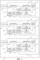
- FIG. 1 illustrates a configuration of a multi-display system (multi-apparatus system) 100 according to a first embodiment of the present invention.
- the multi-display system 100 includes a plurality of (three in this embodiment) projectors (image display apparatuses) 101, 201, and 301 as controllable apparatuses.
- a projector 101 has a light source unit 103 including a discharge lamp or a solid-state light source (laser element or the like), a panel unit 104 such as a liquid crystal panel and a digital micromirror device as a light modulation element, and an image processor 106 that processes a video signal from the outside.
- the image processor 106 generates a panel driving signal according to the input video signal and supplies it to the panel unit 104.
- the panel unit 104 operates so as to modulate the illumination light from the light source unit 103 according to the panel driving signal.
- the image light modulated by the panel unit 104 is magnified by a lens unit 105 and projected on a screen SC. Thereby, a projection image 102 is displayed on the screen SC.
- the lens unit 105 has a focusing function, a zooming function, an aperture adjusting function, and a lens shifting function.
- a plurality of panel units 104 may be provided so as to correspond to a plurality of color light beams such as R, G, and B, and to modulate each color light, or a plurality of color lights may be modulated in a time-series manner by a single panel unit 104.
- An on-screen display (OSD) unit 107 generates and supplies to the image processor 106 an OSD image signal for displaying an OSD image including a menu (referred to as an OSD menu hereinafter) for the user to perform various settings and adjustments, a pointer, various messages, charts, and the like.
- the image processor 106 generates a panel driving signal according to the OSD image signal and supplies the panel driving signal to the panel unit 104. Thereby, the OSD image is displayed on the screen SC together with the projection image or separately from the projection image.
- a memory 108 stores various setting values, state values, computer programs, and the like.
- a communicator 109 communicates with other projectors 201 and 301 via a wireless or wired communication line 113.
- An operation unit 110 has operation members such as buttons and dials, and accepts user operations (referred to as user operations hereinafter) on operation members.
- the operation unit 110 may be provided integrally with the projector 101, or may be provided as a remote controlling device separate from the projector 101.
- the controller 111 controls an overall operation of the projector 101 according to a signal from the operation unit 110 that is operated by the user.
- Each of the other projectors 201 and 301 has the same configuration as the projector 101, and the same elements as those in the projector 101 in the projectors 201 and 301 will be respectively designated by replacing with first number 1 of the reference numerals of the elements of the projector 101 with 2 and 3.
- the number of projectors is not limited to three, and may be two or more.
- FIG. 2 illustrates a multi-display system in which three laterally arranged projectors 101, 201, and 301 display projection images 102, 202, and 302, respectively
- FIG. 3 illustrates a multi-display system in which three vertically arranged projectors 101, 201, and 301 display projection images 102, 202, and 302, respectively.
- projector arrangement information information indicating the number of projectors, an arrangement direction, an arrangement order, and a rotation is generated as information on their arrangement (referred to as projector arrangement information hereinafter), as illustrated in FIG. 4 .
- the arrangement direction is lateral as illustrated in FIG. 2 and vertical as illustrated in FIG. 3 .
- the arrangement order is shown by (X, Y), where X is the lateral order and Y is the vertical order.
- the arrangement order is (1, 1), (2, 1), and (3, 1)
- the arrangement order is (1, 1), (1, 2) and (1, 3).
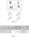
- the arrangement direction has a lattice in which the lateral arrangement and vertical arrangement are combined, and the arrangement order at this time is (1, 1), (1, 2), (2, 1), and (2, 2).
- the lattice includes not only the n ⁇ n square lattice illustrated in FIG. 10 but also n ⁇ m (n ⁇ m).
- the rotation information indicates an installed orientation of each projector such as a flat placement (0 degree), a vertical orientation (90°), and a ceiling mount (180°).
- the projector arrangement information when three vertically oriented projectors 101, 201, and 301 are laterally arranged as illustrated in FIG. 13 is as illustrated in FIG. 14 . If the arrangement direction of the projectors 101, 201, and 301 is different from that of the projection images 102, 202, and 302 on the screen SC, the arrangement direction of the projection images may be set to the arrangement direction information.
- Such projector arrangement information may be generated by the user inputting information on the number of projectors, the arrangement direction, the arrangement order, and the rotation, or may be generated from adjacent information detected from an adjacency status between each projector and another adjacent projector or information obtained by detecting a rotation (installed) orientation of itself.
- the adjacency information can be detected by a connection sensor or an adjacency sensor provided at a plurality of locations of each projector, and can also be detected by detection processing from a captured image obtained by a camera capturing the multi-display system.
- the rotation state may be detected by a gravity sensor provided to each projector.
- the projector arrangement information is stored in the memory 108 together with unique identification information of each projector and connection detection information between the projectors.
- the identification information is used to identify a model or manufacturing number of each projector, or given only within the three projectors.
- the connection detection information can be used as the arrangement direction information.
- FIG. 5 illustrates the appearance of the operation unit 110 provided in the projector 101 as the main (parent) projector.
- the projector 101 and the projectors 201 and 301 as sub (child) projectors are controlled according to a user operation on the operation unit 110.
- the operation unit 110 may be provided as a remote control device separate from the projector 101.
- the operation unit 110 includes a power button 501 for turning on/off the power of the projector, a menu button 502 for displaying an OSD menu on the projector, direction buttons 503 to 506 for instructing up, right, down, and left, an OK button 507 for instructing a decision, and left, upper, lower, and right switching buttons 508 to 511 for switching a projector to be controlled (control target apparatus: referred to as a control target projector hereinafter) among the projectors 101, 201, and 301 to the left, upper, lower, and right.
- the operation unit 110 further includes a zoom-out button 512 and a zoom-in button 513 that cause the control target projector to zoom in and out (optical zoom or electronic zoom) of the projection image.
- the operation unit 110 serves as a detection unit that detects the user operation of the buttons 501 to 513.
- the memory 108 stores the identification information of the projectors 101, 201, and 301, the projector arrangement information, and the connection detection information, as described above.
- a controller 111 selects a control target projector according to a user operation (input) detected by the operation unit 110, or controls for adjustment when the control target projector is the projector 101 (referred to as an adjustment control hereinafter), or makes a communication for causing another control target projector to perform an adjustment control via the communicator 109.
- the adjustment means adjusting the luminance, contrast, sharpness, or other image quality items of the projection image by controlling the image processor 106 or the panel unit 104, and focusing, zooming, aperture adjusting and lens shifting in the lens unit 105 (position of the projected image).
- the operation unit 110, the memory 108, and the controller 111 constitute an operation device.
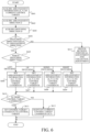
- FIG. 6 shows processing executed by the controller 111 as a computer according to a computer program.
- the controller 111 acquires an arrangement order (X, Y) from the currently control target projector.
- the controller 111 acquires arrangement directions Z (horizontal, vertical, or grid) of all projectors.
- the controller 111 acquires a switching direction D input by a user operation on any of the switching buttons 508 to 511.
- the controller 111 determines whether or not the switching direction D is the direction corresponding to the arrangement direction Z (the same direction). If it is the corresponding direction, it proceeds to the step S605, and if not, it proceeds to the step S613.
- the switching direction D input by the user operation through the switching buttons 508 and 511 is the same direction
- the arrangement direction Z is vertical
- the switching direction D input by the user operation through the switching buttons 509 and 510 is the same direction.
- the arrangement direction Z is a grid
- the switching direction D input by the user operation through any of the switching buttons 508 to 511 is the same direction.
- the controller 111 selects a candidate projector that is a candidate for the next control target projector according to the switching direction D. More specifically, when a switch to the left is input by the user operation through the switch button 508, the controller 111 selects a projector whose arrangement order is (X-1, Y) as a new candidate projector in the step S606. When up, down, or right switching is input by the user operation through the switching buttons 509 to 511, projectors whose arrangement orders of (X, Y+1), (X, Y-1) or (X + 1, Y) are selected as new candidate projectors in the step S607, S608, or S609, respectively.
- the controller 111 determines in the step S610 whether or not there is a candidate projector. If it exists, the flow proceeds to the step S611, and the controller 111 sets the candidate projector selected in any of steps S606 to S609 to a new control target projector. For example, when the flow proceeds from the step S606 to the step S610, the candidate projector whose arrangement order is (X-1, Y) is set to a new control target projector. On the other hand, when there is no candidate projector, the controller 111 proceeds to the step S612 and sets the current controlled projector again to a new controlled projector.
- the controller 111 performs the adjustment control for the projector 101 according to the user operation through the buttons 502 to 503 or 512 and 513.
- the control target projector is the projector 201 or 301
- the control target projector is caused to perform the adjustment control according to the user operation through the buttons 502 to 503 or 512 and 513. Then, the controller 111 ends this processing.
- the controller 111 that has proceeded to the step S613 switches between an individual adjustment control only for the selected control target projector among the projectors 101, 201, and 301 (referred to as individual adjustment hereinafter) and a collective adjustment control of all projectors 101, 201, and 301 (referred to as a collective (or batch or simultaneous) adjustment hereinafter). That is, when the individual adjustment is currently set, it is switched to the collective adjustment, and when the collective adjustment is currently set, it is switched to the individual adjustment.
- the controller 111 performs the adjustment control of the projector 101 according to the user operation through the buttons 502 to 503 or 512 and 513, and causes the projectors 201, 301 to perform the adjustment control via the communicators 109, 209, and 309. Then, the controller 111 ends this processing.
- the individual adjustment of the projector 101 as the control target projector is currently set, and the three projectors 101, 201, and 301 are laterally arranged as illustrated in FIG. 2 .
- the control target projector is switched to the projector 201.
- the projectors 101, 201, and 301 share the projector arrangement information illustrated in FIG. 4
- the projectors 201 and 301 can recognize from the projector arrangement information that they have been selected as the control target projectors.
- the projector arrangement information is shared among the projectors 101, 201, and 301 by the user inputting the projector arrangement information to each projector, or by transmitting and receiving data of the projector arrangement information among the projectors 101, 201, and 301.
- all the projectors 101, 201, and 301 may accept the user operation for the adjustment control of the operation units 110, 210, and 310.
- the operation of individually or collectively adjusting projectors may be configured such that a single projector accepts the operation and notifies the other projectors of the operation contents, or of the adjustment contents.
- Switching of the control target projector and switching between the individual adjustment and the collective adjustment can be performed even while the adjustment menu is displayed.
- the image quality adjustment can be performed while the control target projector is switched. This is similarly applied when the input switching menu is being displayed or the test pattern is being displayed.
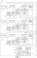
- FIG. 7 illustrates a configuration of a multi-display system 700 according to a second embodiment of the present invention.
- the multi-display system 700 includes three projectors 101, 201, and 301 and a terminal device 701 serving as an operation apparatus.
- the projectors 101, 201 and 301 are caused to perform the adjustment controls through the terminal device 701.
- the configurations of the projectors 101, 201, and 301 are the same as those in the first embodiment.
- the terminal device 701 includes a communicator 702, a display unit 703, an operation unit 704, a memory 705, and a controller 706, and is configured as, for example, a tablet computer or a smartphone.
- the communicator 702 communicates with the projectors 101, 201, and 301 via a wireless or wired communication line 707.
- the display unit 703 is a flat display such as liquid crystal or organic EL
- the operation unit 704 is a touch sensor such as a digitizer.
- the actual operation unit 704 is disposed so as to overlap the display unit 703, and the user can operate the operation unit 704 with a finger or the like while watching the display on the display unit 703.
- the memory 705 stores the projector arrangement information described in the first embodiment together with the computer program and various set values.
- the controller 706 controls the terminal device 701 according to the computer program, or causes the projectors 101, 201, and 301 to perform the adjustment controls via the communicator 702.
- the controller 706 performs the same control processing as the processing illustrated in FIG. 6 executed by the controller 111 in the first embodiment for the adjustment controls over the projectors 101, 201, and 301. Since the operation unit 704 as a touch sensor is provided in the terminal device 701, the controller 706 must detect the direction of a swipe operation (such as a finger sliding operation) as the user operation on the touch sensor. Therefore, in the step S603 in FIG. 6 , the controller 706 acquires the direction of the swipe operation (referred to as a swipe direction hereinafter) as the switching direction D. Then, in the step S604, the controller 706 determines whether or not the swipe direction corresponds to the arrangement direction Z.
- a swipe direction such as a finger sliding operation
- the direction corresponding to the arrangement direction Z in this embodiment includes a direction that is the same as or close to the arrangement direction Z.
- the flow proceeds to the step S613 to switch between the individual adjustment and the collective adjustment.
- the controller 706 is not provided to the projector 101 and thus, similar to the other projectors 201 and 301, makes a communication for causing the projector 101 to perform the adjustment control according to the setting of the control target projector or the collective adjustment setting.
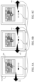
- FIG. 8A illustrates a display example on the display unit 703 in the terminal device 701.
- a display example is illustrated in which the projectors 101, 201, and 301 are laterally arranged as illustrated in FIG. 2 .
- a navigation icon 805 and an adjustment menu 808 are displayed on the display unit 703.
- the navigation icon 805 has three rectangular, laterally arranged frames corresponding to the arrangement of the three projectors 101, 201, and 301, and the position of the control target projector (or which projector is a control target projector) through the position of the rectangular frame in inverted black.
- the adjustment menu 808 displays the luminance, contrast, sharpness, or other image quality item setting values (adjustment states) of the control target projector.
- FIGs. 8A to 8C and 9A to 9D show relationships between the swipe direction for the operation unit 704 on the display unit 703 and the display on the display unit 703.
- FIG. 8A displays the navigation icon 805 showing that the projector 101 is currently set to the control target projector, and the adjustment state of the projector 101. In this state, when the swipe operation is performed to left 801 corresponding to the arrangement direction, the display of the navigation icon 805 and the adjustment menu 808 is switched as illustrated in FIG. 8B . This allows the user to confirm the fact that the projector 201 is currently set to the control target projector and the adjustment state of the projector 201.
- FIGs. 8A to 8C and 9A to 9C are similar for drawing convenience, but they are different originally.
- the switching of the control target projector and the switching between the individual adjustment and the collective adjustment can be operated even while the adjustment menu 808 is displayed.
- the input position of the swipe operation is determined by determining whether there is an input to the outside the adjustment item area of the adjustment menu 808. Thereby, for example, the image quality can be adjusted while the control target projector is being switched. This is similarly applicable when the input switching menu is being displayed or the test pattern is being displayed.
- the navigation icons 805 are also displayed as three vertically arranged rectangular frames, and the position of the control target projector is displayed according to the position of the black inverted rectangular frame. Then, the display of the control target projector and the adjustment menu is switched according to the vertical swipe operation, and the individual adjustment and the collective adjustment are switched according to the horizontal swipe operation.
- FIG. 11 illustrates the IP address of each projector stored in the memory 705 together with the identification information, the projector arrangement information, and the connection detection information.
- an IP address of the communication partner may be switched.
- all the projectors may be set to the communication partners by the broadcast communication, or communications may be made with all the projectors while the IP address is sequentially and individually switched.
- the broadcast communications may be always made with all projectors, and the identification information for identifying the control target projector may be included in the communication packet.
- a communication packet illustrated in FIG. 12 may be defined.
- This communication packet includes identification information (ID) of a terminal device as transmission source ID 1201, transmission destination ID 1202, a command 1203, and error detecting data 1204.
- ID identification information
- IDs that mean all projectors are also prepared.
- a multi-display system including a plurality of projectors has been described, but a device system including a plurality of other controllable apparatuses may be configured.
- Embodiment(s) of the present invention can also be realized by a computer of a system or apparatus that reads out and executes computer executable instructions (e.g., one or more programs) recorded on a storage medium (which may also be referred to more fully as a 'non-transitory computer-readable storage medium') to perform the functions of one or more of the above-described embodiment(s) and/or that includes one or more circuits (e.g., application specific integrated circuit (ASIC)) for performing the functions of one or more of the above-described embodiment(s), and by a method performed by the computer of the system or apparatus by, for example, reading out and executing the computer executable instructions from the storage medium to perform the functions of one or more of the above-described embodiment(s) and/or controlling the one or more circuits to perform the functions of one or more of the above-described embodiment(s).
- computer executable instructions e.g., one or more programs
- a storage medium which may also be referred to more fully as
- the computer may comprise one or more processors (e.g., central processor (CPU), microprocessor (MPU)) and may include a network of separate computers or separate processors to read out and execute the computer executable instructions.
- the computer executable instructions may be provided to the computer, for example, from a network or the storage medium.
- the storage medium may include, for example, one or more of a hard disk, a random-access memory (RAM), a read only memory (ROM), a storage of distributed computing systems, an optical disk (such as a compact disc (CD), digital versatile disc (DVD), or Blu-ray Disc (BD) TM ), a flash memory device, a memory card, and the like.
- a user can easily control a plurality of control target apparatuses.
Landscapes
- Engineering & Computer Science (AREA)
- Multimedia (AREA)
- Signal Processing (AREA)
- Theoretical Computer Science (AREA)
- Physics & Mathematics (AREA)
- General Physics & Mathematics (AREA)
- Human Computer Interaction (AREA)
- General Engineering & Computer Science (AREA)
- Controls And Circuits For Display Device (AREA)
- User Interface Of Digital Computer (AREA)
- Transforming Electric Information Into Light Information (AREA)
- Selective Calling Equipment (AREA)
- Projection Apparatus (AREA)
- Optics & Photonics (AREA)
Priority Applications (1)
| Application Number | Priority Date | Filing Date | Title |
|---|---|---|---|
| EP23181170.4A EP4239466A3 (en) | 2019-10-04 | 2020-09-28 | Operation apparatus, multi-apparatus system, control method, and program |
Applications Claiming Priority (1)
| Application Number | Priority Date | Filing Date | Title |
|---|---|---|---|
| JP2019183836A JP2021060724A (ja) | 2019-10-04 | 2019-10-04 | マルチ装置システムの操作装置および制御方法 |
Related Child Applications (1)
| Application Number | Title | Priority Date | Filing Date |
|---|---|---|---|
| EP23181170.4A Division EP4239466A3 (en) | 2019-10-04 | 2020-09-28 | Operation apparatus, multi-apparatus system, control method, and program |
Publications (2)
| Publication Number | Publication Date |
|---|---|
| EP3800881A1 EP3800881A1 (en) | 2021-04-07 |
| EP3800881B1 true EP3800881B1 (en) | 2023-07-26 |
Family
ID=72665104
Family Applications (2)
| Application Number | Title | Priority Date | Filing Date |
|---|---|---|---|
| EP20198668.4A Active EP3800881B1 (en) | 2019-10-04 | 2020-09-28 | Operation apparatus, multi-apparatus system, control method, and program |
| EP23181170.4A Withdrawn EP4239466A3 (en) | 2019-10-04 | 2020-09-28 | Operation apparatus, multi-apparatus system, control method, and program |
Family Applications After (1)
| Application Number | Title | Priority Date | Filing Date |
|---|---|---|---|
| EP23181170.4A Withdrawn EP4239466A3 (en) | 2019-10-04 | 2020-09-28 | Operation apparatus, multi-apparatus system, control method, and program |
Country Status (3)
| Country | Link |
|---|---|
| US (2) | US11297288B2 (enExample) |
| EP (2) | EP3800881B1 (enExample) |
| JP (1) | JP2021060724A (enExample) |
Families Citing this family (1)
| Publication number | Priority date | Publication date | Assignee | Title |
|---|---|---|---|---|
| CN115793845B (zh) * | 2022-10-10 | 2023-08-08 | 北京城建集团有限责任公司 | 一种基于全息影像的智慧展厅系统 |
Family Cites Families (11)
| Publication number | Priority date | Publication date | Assignee | Title |
|---|---|---|---|---|
| US7948448B2 (en) | 2004-04-01 | 2011-05-24 | Polyvision Corporation | Portable presentation system and methods for use therewith |
| JP5649418B2 (ja) * | 2010-11-26 | 2015-01-07 | シャープ株式会社 | ディスプレイ画面調整装置 |
| US9372657B2 (en) * | 2012-06-11 | 2016-06-21 | Nec Display Solutions, Ltd. | Multi-screen display system, display device, ID setting apparatus, and ID setting method |
| JP2014107713A (ja) * | 2012-11-28 | 2014-06-09 | Seiko Epson Corp | 操作方法、操作プログラム及び操作装置 |
| KR102198783B1 (ko) | 2014-04-11 | 2021-01-05 | 삼성전자주식회사 | 복수 개의 디스플레이 장치를 이용하여 영상을 표시하는 방법 및, 복수 개의 디스플레이 장치를 제어하는 전자 장치 |
| JP6545034B2 (ja) * | 2015-08-19 | 2019-07-17 | キヤノン株式会社 | 表示装置、表示方法及び表示システム |
| JP2017161747A (ja) | 2016-03-10 | 2017-09-14 | Necディスプレイソリューションズ株式会社 | 表示装置、表示装置の表示制御方法 |
| JP6693342B2 (ja) * | 2016-08-31 | 2020-05-13 | セイコーエプソン株式会社 | 表示システム、及び表示システムの制御方法 |
| JP6345316B2 (ja) | 2017-06-14 | 2018-06-20 | キヤノン株式会社 | プロジェクタ、その制御方法、プログラム、及び記憶媒体 |
| JP6897386B2 (ja) | 2017-07-25 | 2021-06-30 | セイコーエプソン株式会社 | マルチプロジェクションシステム、プロジェクターおよびプロジェクターの制御方法 |
| JP6894801B2 (ja) | 2017-08-10 | 2021-06-30 | キヤノン株式会社 | 被制御装置およびその制御方法、プログラム並びに記憶媒体 |
-
2019
- 2019-10-04 JP JP2019183836A patent/JP2021060724A/ja active Pending
-
2020
- 2020-09-25 US US17/032,147 patent/US11297288B2/en active Active
- 2020-09-28 EP EP20198668.4A patent/EP3800881B1/en active Active
- 2020-09-28 EP EP23181170.4A patent/EP4239466A3/en not_active Withdrawn
-
2022
- 2022-03-08 US US17/689,097 patent/US11570409B2/en active Active
Also Published As
| Publication number | Publication date |
|---|---|
| EP3800881A1 (en) | 2021-04-07 |
| US20210105447A1 (en) | 2021-04-08 |
| EP4239466A3 (en) | 2023-11-15 |
| US11297288B2 (en) | 2022-04-05 |
| EP4239466A2 (en) | 2023-09-06 |
| US11570409B2 (en) | 2023-01-31 |
| US20220201260A1 (en) | 2022-06-23 |
| JP2021060724A (ja) | 2021-04-15 |
Similar Documents
| Publication | Publication Date | Title |
|---|---|---|
| US9494846B2 (en) | Projection display device for setting a projection range based on a location specified by an electronic pen and method of controlling the same | |
| US9906762B2 (en) | Communication apparatus, method of controlling communication apparatus, non-transitory computer-readable storage medium | |
| US20110231791A1 (en) | Image display system, graphical user interface, and image display method | |
| JP2014107713A (ja) | 操作方法、操作プログラム及び操作装置 | |
| US20050128530A1 (en) | Image projection control apparatus capable of displaying a plurality of images | |
| US20170052752A1 (en) | Image display system, information processing apparatus, and image display method | |
| US8511830B2 (en) | Projection system, control method for projection system, and projection apparatus | |
| CN110018778B (zh) | 通信设备、显示设备及其控制方法、存储介质和显示系统 | |
| US8917345B2 (en) | Multi-display digital image processing apparatus using external display apparatus for simultaneous display of slide show at different speeds, with related method and computer readable recording medium | |
| JP2017182110A (ja) | 表示システム、表示装置、情報処理装置及び情報処理方法 | |
| EP2824936A1 (en) | Projector, projector control method, and recording medium storing projector control program | |
| US11570409B2 (en) | Operation apparatus, multi-apparatus system, control method, and storage medium | |
| WO2014141612A1 (ja) | 撮像装置 | |
| US20220116571A1 (en) | Control device, and control method | |
| US11330187B2 (en) | Electronic apparatus, method of controlling electronic apparatus, and storage medium | |
| US10397531B2 (en) | Projector, display device, and display method | |
| US11706393B2 (en) | Projection-type display device and method for adjusting a projected image | |
| US11238828B2 (en) | Method of controlling display device and display device | |
| US12423040B2 (en) | Control apparatus, image pickup system, control method, and storage medium | |
| US11144273B2 (en) | Image display apparatus having multiple operation modes and control method thereof | |
| JP6894801B2 (ja) | 被制御装置およびその制御方法、プログラム並びに記憶媒体 | |
| US11934616B2 (en) | Image display system, method for controlling image display system, and method for controlling display apparatus | |
| JP2007079240A (ja) | 画像表示装置及び画像表示方法 | |
| US11516404B2 (en) | Control apparatus and control method | |
| JP2024171090A (ja) | 制御装置、画像投射システム、画像投射装置、制御方法およびプログラム |
Legal Events
| Date | Code | Title | Description |
|---|---|---|---|
| PUAI | Public reference made under article 153(3) epc to a published international application that has entered the european phase |
Free format text: ORIGINAL CODE: 0009012 |
|
| STAA | Information on the status of an ep patent application or granted ep patent |
Free format text: STATUS: THE APPLICATION HAS BEEN PUBLISHED |
|
| AK | Designated contracting states |
Kind code of ref document: A1 Designated state(s): AL AT BE BG CH CY CZ DE DK EE ES FI FR GB GR HR HU IE IS IT LI LT LU LV MC MK MT NL NO PL PT RO RS SE SI SK SM TR |
|
| AX | Request for extension of the european patent |
Extension state: BA ME |
|
| STAA | Information on the status of an ep patent application or granted ep patent |
Free format text: STATUS: REQUEST FOR EXAMINATION WAS MADE |
|
| 17P | Request for examination filed |
Effective date: 20211007 |
|
| RBV | Designated contracting states (corrected) |
Designated state(s): AL AT BE BG CH CY CZ DE DK EE ES FI FR GB GR HR HU IE IS IT LI LT LU LV MC MK MT NL NO PL PT RO RS SE SI SK SM TR |
|
| GRAP | Despatch of communication of intention to grant a patent |
Free format text: ORIGINAL CODE: EPIDOSNIGR1 |
|
| STAA | Information on the status of an ep patent application or granted ep patent |
Free format text: STATUS: GRANT OF PATENT IS INTENDED |
|
| INTG | Intention to grant announced |
Effective date: 20230214 |
|
| GRAS | Grant fee paid |
Free format text: ORIGINAL CODE: EPIDOSNIGR3 |
|
| GRAA | (expected) grant |
Free format text: ORIGINAL CODE: 0009210 |
|
| STAA | Information on the status of an ep patent application or granted ep patent |
Free format text: STATUS: THE PATENT HAS BEEN GRANTED |
|
| AK | Designated contracting states |
Kind code of ref document: B1 Designated state(s): AL AT BE BG CH CY CZ DE DK EE ES FI FR GB GR HR HU IE IS IT LI LT LU LV MC MK MT NL NO PL PT RO RS SE SI SK SM TR |
|
| REG | Reference to a national code |
Ref country code: CH Ref legal event code: EP |
|
| REG | Reference to a national code |
Ref country code: IE Ref legal event code: FG4D |
|
| REG | Reference to a national code |
Ref country code: DE Ref legal event code: R096 Ref document number: 602020014359 Country of ref document: DE |
|
| REG | Reference to a national code |
Ref country code: LT Ref legal event code: MG9D |
|
| REG | Reference to a national code |
Ref country code: NL Ref legal event code: MP Effective date: 20230726 |
|
| REG | Reference to a national code |
Ref country code: AT Ref legal event code: MK05 Ref document number: 1593322 Country of ref document: AT Kind code of ref document: T Effective date: 20230726 |
|
| PG25 | Lapsed in a contracting state [announced via postgrant information from national office to epo] |
Ref country code: NL Free format text: LAPSE BECAUSE OF FAILURE TO SUBMIT A TRANSLATION OF THE DESCRIPTION OR TO PAY THE FEE WITHIN THE PRESCRIBED TIME-LIMIT Effective date: 20230726 |
|
| PG25 | Lapsed in a contracting state [announced via postgrant information from national office to epo] |
Ref country code: GR Free format text: LAPSE BECAUSE OF FAILURE TO SUBMIT A TRANSLATION OF THE DESCRIPTION OR TO PAY THE FEE WITHIN THE PRESCRIBED TIME-LIMIT Effective date: 20231027 |
|
| PG25 | Lapsed in a contracting state [announced via postgrant information from national office to epo] |
Ref country code: IS Free format text: LAPSE BECAUSE OF FAILURE TO SUBMIT A TRANSLATION OF THE DESCRIPTION OR TO PAY THE FEE WITHIN THE PRESCRIBED TIME-LIMIT Effective date: 20231126 |
|
| PG25 | Lapsed in a contracting state [announced via postgrant information from national office to epo] |
Ref country code: SE Free format text: LAPSE BECAUSE OF FAILURE TO SUBMIT A TRANSLATION OF THE DESCRIPTION OR TO PAY THE FEE WITHIN THE PRESCRIBED TIME-LIMIT Effective date: 20230726 Ref country code: RS Free format text: LAPSE BECAUSE OF FAILURE TO SUBMIT A TRANSLATION OF THE DESCRIPTION OR TO PAY THE FEE WITHIN THE PRESCRIBED TIME-LIMIT Effective date: 20230726 Ref country code: PT Free format text: LAPSE BECAUSE OF FAILURE TO SUBMIT A TRANSLATION OF THE DESCRIPTION OR TO PAY THE FEE WITHIN THE PRESCRIBED TIME-LIMIT Effective date: 20231127 Ref country code: NO Free format text: LAPSE BECAUSE OF FAILURE TO SUBMIT A TRANSLATION OF THE DESCRIPTION OR TO PAY THE FEE WITHIN THE PRESCRIBED TIME-LIMIT Effective date: 20231026 Ref country code: LV Free format text: LAPSE BECAUSE OF FAILURE TO SUBMIT A TRANSLATION OF THE DESCRIPTION OR TO PAY THE FEE WITHIN THE PRESCRIBED TIME-LIMIT Effective date: 20230726 Ref country code: LT Free format text: LAPSE BECAUSE OF FAILURE TO SUBMIT A TRANSLATION OF THE DESCRIPTION OR TO PAY THE FEE WITHIN THE PRESCRIBED TIME-LIMIT Effective date: 20230726 Ref country code: IS Free format text: LAPSE BECAUSE OF FAILURE TO SUBMIT A TRANSLATION OF THE DESCRIPTION OR TO PAY THE FEE WITHIN THE PRESCRIBED TIME-LIMIT Effective date: 20231126 Ref country code: HR Free format text: LAPSE BECAUSE OF FAILURE TO SUBMIT A TRANSLATION OF THE DESCRIPTION OR TO PAY THE FEE WITHIN THE PRESCRIBED TIME-LIMIT Effective date: 20230726 Ref country code: GR Free format text: LAPSE BECAUSE OF FAILURE TO SUBMIT A TRANSLATION OF THE DESCRIPTION OR TO PAY THE FEE WITHIN THE PRESCRIBED TIME-LIMIT Effective date: 20231027 Ref country code: FI Free format text: LAPSE BECAUSE OF FAILURE TO SUBMIT A TRANSLATION OF THE DESCRIPTION OR TO PAY THE FEE WITHIN THE PRESCRIBED TIME-LIMIT Effective date: 20230726 Ref country code: AT Free format text: LAPSE BECAUSE OF FAILURE TO SUBMIT A TRANSLATION OF THE DESCRIPTION OR TO PAY THE FEE WITHIN THE PRESCRIBED TIME-LIMIT Effective date: 20230726 |
|
| PG25 | Lapsed in a contracting state [announced via postgrant information from national office to epo] |
Ref country code: PL Free format text: LAPSE BECAUSE OF FAILURE TO SUBMIT A TRANSLATION OF THE DESCRIPTION OR TO PAY THE FEE WITHIN THE PRESCRIBED TIME-LIMIT Effective date: 20230726 |
|
| PG25 | Lapsed in a contracting state [announced via postgrant information from national office to epo] |
Ref country code: ES Free format text: LAPSE BECAUSE OF FAILURE TO SUBMIT A TRANSLATION OF THE DESCRIPTION OR TO PAY THE FEE WITHIN THE PRESCRIBED TIME-LIMIT Effective date: 20230726 |
|
| REG | Reference to a national code |
Ref country code: DE Ref legal event code: R097 Ref document number: 602020014359 Country of ref document: DE |
|
| PG25 | Lapsed in a contracting state [announced via postgrant information from national office to epo] |
Ref country code: SM Free format text: LAPSE BECAUSE OF FAILURE TO SUBMIT A TRANSLATION OF THE DESCRIPTION OR TO PAY THE FEE WITHIN THE PRESCRIBED TIME-LIMIT Effective date: 20230726 Ref country code: RO Free format text: LAPSE BECAUSE OF FAILURE TO SUBMIT A TRANSLATION OF THE DESCRIPTION OR TO PAY THE FEE WITHIN THE PRESCRIBED TIME-LIMIT Effective date: 20230726 Ref country code: ES Free format text: LAPSE BECAUSE OF FAILURE TO SUBMIT A TRANSLATION OF THE DESCRIPTION OR TO PAY THE FEE WITHIN THE PRESCRIBED TIME-LIMIT Effective date: 20230726 Ref country code: EE Free format text: LAPSE BECAUSE OF FAILURE TO SUBMIT A TRANSLATION OF THE DESCRIPTION OR TO PAY THE FEE WITHIN THE PRESCRIBED TIME-LIMIT Effective date: 20230726 Ref country code: DK Free format text: LAPSE BECAUSE OF FAILURE TO SUBMIT A TRANSLATION OF THE DESCRIPTION OR TO PAY THE FEE WITHIN THE PRESCRIBED TIME-LIMIT Effective date: 20230726 Ref country code: CZ Free format text: LAPSE BECAUSE OF FAILURE TO SUBMIT A TRANSLATION OF THE DESCRIPTION OR TO PAY THE FEE WITHIN THE PRESCRIBED TIME-LIMIT Effective date: 20230726 Ref country code: SK Free format text: LAPSE BECAUSE OF FAILURE TO SUBMIT A TRANSLATION OF THE DESCRIPTION OR TO PAY THE FEE WITHIN THE PRESCRIBED TIME-LIMIT Effective date: 20230726 |
|
| REG | Reference to a national code |
Ref country code: CH Ref legal event code: PL |
|
| PG25 | Lapsed in a contracting state [announced via postgrant information from national office to epo] |
Ref country code: LU Free format text: LAPSE BECAUSE OF NON-PAYMENT OF DUE FEES Effective date: 20230928 |
|
| REG | Reference to a national code |
Ref country code: BE Ref legal event code: MM Effective date: 20230930 |
|
| PG25 | Lapsed in a contracting state [announced via postgrant information from national office to epo] |
Ref country code: LU Free format text: LAPSE BECAUSE OF NON-PAYMENT OF DUE FEES Effective date: 20230928 Ref country code: IT Free format text: LAPSE BECAUSE OF FAILURE TO SUBMIT A TRANSLATION OF THE DESCRIPTION OR TO PAY THE FEE WITHIN THE PRESCRIBED TIME-LIMIT Effective date: 20230726 Ref country code: MC Free format text: LAPSE BECAUSE OF FAILURE TO SUBMIT A TRANSLATION OF THE DESCRIPTION OR TO PAY THE FEE WITHIN THE PRESCRIBED TIME-LIMIT Effective date: 20230726 |
|
| PLBE | No opposition filed within time limit |
Free format text: ORIGINAL CODE: 0009261 |
|
| STAA | Information on the status of an ep patent application or granted ep patent |
Free format text: STATUS: NO OPPOSITION FILED WITHIN TIME LIMIT |
|
| 26N | No opposition filed |
Effective date: 20240429 |
|
| REG | Reference to a national code |
Ref country code: IE Ref legal event code: MM4A |
|
| PG25 | Lapsed in a contracting state [announced via postgrant information from national office to epo] |
Ref country code: IE Free format text: LAPSE BECAUSE OF NON-PAYMENT OF DUE FEES Effective date: 20230928 |
|
| PG25 | Lapsed in a contracting state [announced via postgrant information from national office to epo] |
Ref country code: CH Free format text: LAPSE BECAUSE OF NON-PAYMENT OF DUE FEES Effective date: 20230930 |
|
| PG25 | Lapsed in a contracting state [announced via postgrant information from national office to epo] |
Ref country code: IE Free format text: LAPSE BECAUSE OF NON-PAYMENT OF DUE FEES Effective date: 20230928 Ref country code: CH Free format text: LAPSE BECAUSE OF NON-PAYMENT OF DUE FEES Effective date: 20230930 Ref country code: SI Free format text: LAPSE BECAUSE OF FAILURE TO SUBMIT A TRANSLATION OF THE DESCRIPTION OR TO PAY THE FEE WITHIN THE PRESCRIBED TIME-LIMIT Effective date: 20230726 |
|
| PG25 | Lapsed in a contracting state [announced via postgrant information from national office to epo] |
Ref country code: BE Free format text: LAPSE BECAUSE OF NON-PAYMENT OF DUE FEES Effective date: 20230930 |
|
| PGFP | Annual fee paid to national office [announced via postgrant information from national office to epo] |
Ref country code: DE Payment date: 20240820 Year of fee payment: 5 |
|
| PGFP | Annual fee paid to national office [announced via postgrant information from national office to epo] |
Ref country code: GB Payment date: 20240822 Year of fee payment: 5 |
|
| PGFP | Annual fee paid to national office [announced via postgrant information from national office to epo] |
Ref country code: FR Payment date: 20240820 Year of fee payment: 5 |
|
| PG25 | Lapsed in a contracting state [announced via postgrant information from national office to epo] |
Ref country code: BG Free format text: LAPSE BECAUSE OF FAILURE TO SUBMIT A TRANSLATION OF THE DESCRIPTION OR TO PAY THE FEE WITHIN THE PRESCRIBED TIME-LIMIT Effective date: 20230726 |
|
| PG25 | Lapsed in a contracting state [announced via postgrant information from national office to epo] |
Ref country code: BG Free format text: LAPSE BECAUSE OF FAILURE TO SUBMIT A TRANSLATION OF THE DESCRIPTION OR TO PAY THE FEE WITHIN THE PRESCRIBED TIME-LIMIT Effective date: 20230726 |
|
| PG25 | Lapsed in a contracting state [announced via postgrant information from national office to epo] |
Ref country code: CY Free format text: LAPSE BECAUSE OF FAILURE TO SUBMIT A TRANSLATION OF THE DESCRIPTION OR TO PAY THE FEE WITHIN THE PRESCRIBED TIME-LIMIT; INVALID AB INITIO Effective date: 20200928 |
|
| PG25 | Lapsed in a contracting state [announced via postgrant information from national office to epo] |
Ref country code: HU Free format text: LAPSE BECAUSE OF FAILURE TO SUBMIT A TRANSLATION OF THE DESCRIPTION OR TO PAY THE FEE WITHIN THE PRESCRIBED TIME-LIMIT; INVALID AB INITIO Effective date: 20200928 |
|
| PG25 | Lapsed in a contracting state [announced via postgrant information from national office to epo] |
Ref country code: TR Free format text: LAPSE BECAUSE OF FAILURE TO SUBMIT A TRANSLATION OF THE DESCRIPTION OR TO PAY THE FEE WITHIN THE PRESCRIBED TIME-LIMIT Effective date: 20230726 |