EP3800434B1 - Waffe, insbesondere ein karabiner - Google Patents
Waffe, insbesondere ein karabiner Download PDFInfo
- Publication number
- EP3800434B1 EP3800434B1 EP19201455.3A EP19201455A EP3800434B1 EP 3800434 B1 EP3800434 B1 EP 3800434B1 EP 19201455 A EP19201455 A EP 19201455A EP 3800434 B1 EP3800434 B1 EP 3800434B1
- Authority
- EP
- European Patent Office
- Prior art keywords
- barrel
- gun
- optionally
- per
- tensioning
- Prior art date
- Legal status (The legal status is an assumption and is not a legal conclusion. Google has not performed a legal analysis and makes no representation as to the accuracy of the status listed.)
- Active
Links
- 230000007246 mechanism Effects 0.000 claims description 16
- 238000010304 firing Methods 0.000 claims description 8
- 239000007789 gas Substances 0.000 description 4
- 230000000295 complement effect Effects 0.000 description 3
- 238000007373 indentation Methods 0.000 description 3
- 230000008859 change Effects 0.000 description 2
- 239000000470 constituent Substances 0.000 description 2
- 238000004519 manufacturing process Methods 0.000 description 2
- 238000012986 modification Methods 0.000 description 2
- 230000004048 modification Effects 0.000 description 2
- 230000009471 action Effects 0.000 description 1
- 230000015572 biosynthetic process Effects 0.000 description 1
- 239000000969 carrier Substances 0.000 description 1
- 230000001419 dependent effect Effects 0.000 description 1
- 230000000694 effects Effects 0.000 description 1
- 239000002360 explosive Substances 0.000 description 1
- 230000003993 interaction Effects 0.000 description 1
- 239000000463 material Substances 0.000 description 1
- 230000013011 mating Effects 0.000 description 1
- 238000000034 method Methods 0.000 description 1
- 229920003023 plastic Polymers 0.000 description 1
- 239000004033 plastic Substances 0.000 description 1
- 230000008569 process Effects 0.000 description 1
- 239000002904 solvent Substances 0.000 description 1
Images


Classifications
-
- F—MECHANICAL ENGINEERING; LIGHTING; HEATING; WEAPONS; BLASTING
- F41—WEAPONS
- F41A—FUNCTIONAL FEATURES OR DETAILS COMMON TO BOTH SMALLARMS AND ORDNANCE, e.g. CANNONS; MOUNTINGS FOR SMALLARMS OR ORDNANCE
- F41A21/00—Barrels; Gun tubes; Muzzle attachments; Barrel mounting means
- F41A21/48—Barrel mounting means, e.g. releasable mountings for replaceable barrels
- F41A21/484—Barrel mounting means, e.g. releasable mountings for replaceable barrels using interlocking means, e.g. by sliding pins
-
- F—MECHANICAL ENGINEERING; LIGHTING; HEATING; WEAPONS; BLASTING
- F41—WEAPONS
- F41A—FUNCTIONAL FEATURES OR DETAILS COMMON TO BOTH SMALLARMS AND ORDNANCE, e.g. CANNONS; MOUNTINGS FOR SMALLARMS OR ORDNANCE
- F41A21/00—Barrels; Gun tubes; Muzzle attachments; Barrel mounting means
- F41A21/48—Barrel mounting means, e.g. releasable mountings for replaceable barrels
- F41A21/481—Barrel mounting means, e.g. releasable mountings for replaceable barrels using partial or interrupted threads, e.g. bayonet-type mountings
-
- F—MECHANICAL ENGINEERING; LIGHTING; HEATING; WEAPONS; BLASTING
- F41—WEAPONS
- F41A—FUNCTIONAL FEATURES OR DETAILS COMMON TO BOTH SMALLARMS AND ORDNANCE, e.g. CANNONS; MOUNTINGS FOR SMALLARMS OR ORDNANCE
- F41A21/00—Barrels; Gun tubes; Muzzle attachments; Barrel mounting means
- F41A21/48—Barrel mounting means, e.g. releasable mountings for replaceable barrels
- F41A21/487—Barrel mounting means, e.g. releasable mountings for replaceable barrels using friction, e.g. by clamping a barrel surface
Definitions
- the invention relates to a gun, in particular a carbine, in accordance with the preamble of claim 1 and the US 2015/308779 , described further below. More specifically, the invention relates to the upper part of the carbine, which contains at least a barrel, a bolt mechanism, a firing pin mechanism, optionally a gas mechanism and a cover. This upper part is removably connected to a lower part, which contains at least a butt, a magazine and a trigger mechanism. Said trigger mechanism is operatively connected to the firing pin mechanism in the assembled ready-to-fire state. In detail, the invention relates to fastening the barrel in the upper part.
- FR 412 523 of 1909 discloses a pistol with a so-called "fixed barrel” barrel which may be dismounted along a guide after a rotatable block in front of it has been turned around an axis which is orientated parallel to the barrel axis. There is no provision to ensure that, the chamber is empty or anything else.
- FR 386 646 of 1908 published under GB 1909 01954 A discloses a similar system.
- the block is rotated around a vertical axis and the barrel is taken off after some movement along the guides by tilting without given axis around its front part.
- This solution has the same disadvantages as the solution described before.
- EP 2 363 678 proposes connecting the barrel to a locking bushing, for example by means of a thread.
- Said locking bushing fits in a circular cylindrical bore in the housing (upper part) and is secured by means of a rotary eccentric.
- a front part of the bolt called the bolt head
- the circular cylindrical bearing of the barrel the angular position of which is only determined by a flat portion that interacts with the eccentric, which portion is never precise, and the "entrainment" of the bolt head are extremely disadvantageous and soon lead to wear and noticeable inaccuracies occurring during use under harsh conditions.
- EP 2 663 826 corresponding to US 9,228,786 , US 8,813,406 , US 8,973,483 , US 9,038,525 and US 9,488,423 (the content of these four US documents is made for the jurisdictions in which they are possible by reference to the content of the present disclosure), which each comprise over 140 pages with over 80 figures, most of which are still divided into views A-F, disclose a connection of a barrel to a "backbone", which is arranged thereabove, by means of a lever (this can be best seen in Fig. 52A-53C).
- the lever consists of two brackets, which are arranged in parallel with the gun center plane on the left and the right of the backbone, and are interconnected by means of a ridge, which is also used as a shaft.
- the backbone comprises an indentation on its upper side, which extends transversely to the barrel shaft, on or in which the ridge is placed from above.
- the upper side of the barrel comprises a point of engagement for the lever on the left- and right-hand side, which point also comprises a prismatic indentation and, when the lever is pulled, is pressed against the circular cylindrical lateral face of the backbone.
- the mounting movement between the barrel and the backbone only takes place normally with respect to the barrel shaft, which is ensured by two additional points of contact that are axially in front of and behind the lever.
- the barrel and backbone therefore have three points of contact with one another.
- the relative position of the two components is set by the indentation for the ridge, the contact between the prism, which is a few millimeters long, and the cylindrical casing of the backbone, and by the two other contact points, which are purely interlocking and therefore tolerance-dependent.
- such a structure is not able to reliably and repeatedly reach an accurate position. There is therefore the risk of the lever getting lost since it is a loose and not particularly large component part.
- the barrel which optionally includes a locking bush that is rigidly connected to said barrel, on the one hand and the upper part of the carbine or a carrier arranged in said upper part on the other hand, corresponding guides, preferably prismatic guide surfaces, which extend in parallel with the barrel shaft in the mounted ready-to-fire state; and, after having been inserted by means of the guides, the barrel is secured on the upper part, using a locking element or a tensioning element, possibly in the form of a cam, which is provided on the upper part; and a force acts on the barrel, optionally the locking bush, in the gun center plane and normally with respect to the movement direction, or interlockingly secures said barrel.
- the barrel shaft is "in the mounted, ready-to-fire state" because under certain circumstances the barrel changes its position during mounting or firing.
- the locking bush can be releasably, for example by a thread, or permanently connected to the barrel.
- the gun center plane should be understood in the conventional sense and extends vertically through the barrel shaft when in the standard firing position.
- the barrel and/or the locking bush rests on a catch, shoulder, stop surface or similar part of the upper.
- the purpose of securing the barrel and/or the locking bush is to hold the barrel in this position and, if the barrel and/or caliber is/are changed, to move said barrel into the intended position of the barrel shaft in a manner that can be accurately reproduced, where it is secured.
- the external dimensions of the barrel or optionally the locking bush are therefore determined by the dimensions of the upper, whereby, having knowledge of the invention, a person skilled in the art can accordingly provide the guides on the barrel or locking bush to the carrier and/or upper.
- the locking element or tensioning element can also additionally exert a force component on the barrel in the movement direction (direction of the barrel shaft) (in order to avoid prolixity, in the following reference will only be made to the locking bush where necessary), but this is less essential to the essence of the invention than the force that is normal with respect to the barrel shaft.
- the tensioning element comprises a tensioning portion, which is preferably formed as a cam and is preferably rotated about the shaft in the upper housing, transversely to the barrel shaft, by means of a lever-shaped actuating portion, to which it is rigidly connected or with which it is integral.
- the guides are preferably prismatic guides, that is guides comprising planar contact surfaces that are oriented in parallel with the barrel shaft and (only) allow the parts to move with respect to one another in this direction. They are therefore referred to as "prismatic" because they constitute parts of the lateral surface of a prism. They are particularly preferably dovetail guides, which allow for particularly accurate and reproducible positioning. Either one such guide is provided or, preferably, a pair of guides, which is/are arranged symmetrically to the gun center plane in order to achieve the best possible guidance. Despite the accuracy of the prismatic guides, the action of the tensioning element or the cam is intended to have a centering effect on the barrel or locking bush due to the angular position of the prisms, as this further improves the positioning reproducibility.
- the tensioning portion is preferably part of a lever, which is mounted in the upper housing (upper) or in a carrier provided therefor, below the barrel, such that it can rotate about an axis of rotation that extends normally with respect to the gun center plane.
- the tensioning element is preferably in contact with the barrel over the entire available width thereof if possible, for which purpose the guides in the upper or carrier can be interrupted at this point when they are provided below the barrel in the region of the tensioning element.
- a toggle or the like can also be provided, which is arranged on the side of the barrel and is connected to the tensioning element.
- the barrel comprises a flat portion on its lower side in the region of the receptacle in the upper and/or the locking bush is also preferable, which flat portion allows for interaction with the tensioning portion over a defined surface area, thereby further increasing the repeatability of the position.
- the guides that are used to receive the barrel (and/or the locking bush) can be formed in or on a carrier, which is connected to or fastened on the upper housing such that it cannot move.
- a carrier which is connected to or fastened on the upper housing such that it cannot move.
- the guides can also be directly provided in the upper housing (upper), whereby a separate carrier can either be completely omitted and therefore the carrier is integral with the upper housing, or this carrier is fixedly connected to the upper housing, as would be the case in a carrier which is overmolded with plastics material, for example.
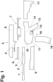
- a carbine in a correspondingly functional view comprising all its equipment, comprises a barrel 1, a gas drive 2, a locking bush 3, an upper housing, in most cases also referred to as an upper 4 outside of the USA, a carrier 5, which in turn comprises guides 6 for a bolt 7 and/or a cocking slide 8 and/or other functional elements, a fore-end 9, a lower housing, also referred to as a lower 10, which in turn comprises a magazine holder 11, a firing device 12, a butt 13 and a slide stop device 14, a central lock 15, a magazine 16 and a stock 17, for example.
- All of these parts do not always have to be provided or the design of which can differ slightly depending on the application, for example in hunting weapons; however, additional parts may conversely also be provided, for example mounting elements for telescopic sights, laser pointers, and so on and so forth.
- Some of said components can also be collectively formed on a more complex component such that they cannot be separated from one another, such as the lower housing or lower 10 in the present case, so that the view only constitutes an example of a very modular carbine.
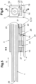
- Fig. 2 is a purely schematic perspective view of the barrel 1, comprising a locking bush 3 in front of the support 5, into which said barrel can be inserted in the direction of the double-headed arrow, which extends in parallel with the barrel shaft 26 ( Fig. 3 ).
- corresponding guides 6 are provided on the locking bush 3 and in the carrier 5, which are prismatic, i.e. the contact surfaces are planar.
- the planes extend in parallel with the double-headed arrow.
- the carrier 5 comprises a frame 52 comprising a carrier plate 51, which surrounds the locking bush 3.
- An actuating portion 18, in the form of a lever here, is arranged in the carrier 5 so as to be rotatable about an axis of rotation 19.
- the carrier 5 is formed as one part, although, according to the invention, carriers 5 composed of a frame 52 and carrier plate 51 can also be used. Likewise, the guides 6 can also be formed on the carrier plate 51 and/or the frame 52.
- the bolt 7 and the firing pin mechanism are not shown, but do not play a part in the invention either.
- the associated lower part 10 of the gun is not shown either since it is of no relevance to the invention.
- a carrier 5 does not necessarily have to be formed separately and fastened in the upper housing 4, but the carrier 5 or the guides 6 can also be integrally formed in the upper housing 4, and therefore a separate view has been omitted here.
- Fig. 3-10 are each a schematic front view of a section through the gun center plane showing four different embodiments of the guides or the tensioning mechanism. Even now, it should be noted that any of the individual variants of the tensioning mechanism can be combined with any of the individual variants of the guides.
- Fig. 3-4 constitute a first possible embodiment, in which the guides 6 are in the form of a dovetail.
- Fig. 3 which is a section through the gun center plane 30, shows in particular the formation of a tensioning element 20 in the upper.
- the guides 6 are formed on the carrier plate 51.
- the tensioning element 20 that is formed as a cam, presses the locking bush 3 of the barrel 1 upwards so that the contact pressure is exerted on the corresponding oblique guide surfaces 23 of the dovetail.
- a planar axial stop surface 22 of the carrier 5 which faces the rear in the position shown, rests against a front 25 of the locking bush 3 and therefore interlockingly secures the barrel 1 in the axial direction by means of the axial stop surface 22 and ultimately non-positively secures said barrel, again in the axial direction, by means of the contact pressure.
- the tensioning element 20 and the fact that it is borne about the axis of rotation 19 in the carrier 5, which also comprises the mating surfaces of the dovetail of the guides 6, is clearly shown, albeit schematically.
- the guides are interrupted in the region of the axis of rotation 19 in order to create space for the tensioning element 20.
- Interlocking relates to the way in which the geometry of the surfaces shown match, but should not be understood in a purely geometrical and mathematical sense, since the positive fit has to take into account vibrations, thermal expansions, impacts, etc. and therefore also always have an axially oriented force component. In this case, as a result of the discontinuation of any movement whatsoever of the barrel in the axial direction in the event of an emergency, which discontinuation is, however, always interlocking, said positive fit is referred to as "interlocking" here.
- Fig. 4 which is a schematic front view in the direction of the arrow IV in Fig. 3 , is a detailed view of the orientation of the oblique guide surfaces 23 of the prismatic guide and the centering element 21, which interacts with said guide surfaces, with respect to the barrel shaft 28.
- a single-part centering element 21 is shown.
- Fig. 5-6 show a variant in which the guides 6 are in the form of a plurality of guide surfaces 23.
- the functional principle of this embodiment is aimed at axially securing the barrel and the locking bush 3 by means of a tensioning element 20 in a similar way to in the previous example.
- the tensioning portion 28 shown in Fig. 5-6 is formed as a claw-shaped or hook-shaped cam in this case, and therefore tensile stress is downwardly applied to an intermediate piece 27, transversely to the barrel shaft 26 (lying in or symmetrically to the gun center plane 20), by the tensioning elements 20 in the closed state.
- the carrier 5, which is shown by way of example, is therefore likewise used to receive the intermediate piece 27, as a result of which the locking bush 3 and therefore the barrel 1 are interlockingly and non-positively connected to the upper 4 when a force is applied by means of the tensioning element 20 in a similar way to in the previous example.
- a counter pusher 24 can be provided, which is arranged mounted on the housing of the upper 4 or of the lever-shaped actuating portion 18, passing through the locking bush 3, or of the locking bush 3 itself.
- Fig. 7-8 show a variant in which the dovetail-like prismatic guide 6 is arranged above the barrel shaft 26, where said shaft can be formed so as to be continuous without any problems.
- the cam-like tensioning portion 28 in turn ensures securing in the axial direction and normally with respect thereto in a similar way to in the above-described variant in Fig. 3-4 .
- the centering element 21 is divided into two sub-elements 21a, 21b, which are formed so as to have a complementary shape and function to the guide surfaces 23 on the upper side of the locking bush 3.
- FIG. 3 A comparison of Fig. 3 with Fig. 5 and 7 clearly shows that, irrespective of the selected embodiment and position of the guide 6 or the design of the carrier 5, the barrel 1 - the locking bush 3 - can comprise a recess in its lower side. This recess can serve as an additional support point or stop surface for the tensioning element 20 or the tensioning portion 28, thereby further improving the repeatable positioning of the barrel 1 inside the upper 4 and the barrel 1 is additionally tensioned together with the locking bush 3 and the upper 4.
- Fig. 9 shows another possible variant, in which the tensioning element 20 is in the form of a hook such that a pin or an undercut (as shown in Fig. 10 ) engages behind the guide 6 and pulls the barrel 1 downwards together with the locking bush 3.
- fastening is carried out by a tensioning element 20 or tensioning portion 18 (not shown in more detail in Fig. 9 and 10 ) centering on the guide surfaces 23 in a similar way to in the above-described examples.
- the centering element 21 is also divided into two sub-elements 21a, 21b, which are formed such that their shape and function is complementary to that of the guide surfaces 23 on the upper side of the locking bush 3.
- a tensioning portion 28 formed in accordance with the invention can be formed as a cam as shown in Fig. 3-4 and 7-8 , whereby a design as an eccentric element or wedge is also conceivable in order to exert a pressure on the locking bush 3 and/or the barrel 1.
- a tensioning portion 28, as shown in Fig. 5-6 and 9-10 can preferably be formed as a claw-shaped or hook-shaped gripping element, whereby variations are likewise conceivable, such as having a trapezoidal cross section in order to engage in undercuts.
- the barrel 1 and optionally the locking bush 3 can additionally be axially secured by means of oblique surfaces on the carrier 5 or the upper 4 in the operating region of the tensioning portion 28, which surfaces are targetedly adapted to one another, such as by an angle of attack of from 1° up to approximately 30°.
- Fig. 2-10 very clearly show, by positioning the barrel 1 inside the upper 4 by means of a tensioning element 20, as per the invention, it is possible that the barrel and/or caliber can be quickly changed with repetition accuracy.
- the actuation of the tensioning element 20 by means of the actuating portion 18 about a center of rotation 19 allows the gun to only be ready to fire after the tensioning portion 28 is "active", i.e. actuated, and therefore the barrel 1 and/or the locking bush 3 is/are rigidly connected to the upper 4.
- the solution according to the invention can prevent the barrel from being inadequately secured, or not being secured at all.
- securing of the barrel 1 as per the invention involves at least one spring element 29, which engages on or inside the tensioning element 20 and pretensions the tensioning portion 28 relative to the barrel 1 and/or the locking bush 3 and/or the intermediate piece 27.
- the spring element 29 can be formed as both a pressure spring and a tension spring.
- Fig. 12-14 show possible embodiments, whereby the spring element 29 is formed as a pressure spring and interacts with the tensioning portion 28.
- the corresponding front views of the sectional views are shown in Fig. 4 analogously to Fig. 3 .
- the spring element is arranged between the locking bush 3 and the barrel 1 by way of example, an alternative arrangement also being conceivable, such as exclusively inside the locking bush 3.
- Fig. 13 shows a variant in which the spring element 29 is arranged hidden inside the tensioning portion 28 in order to exert the compressive force, the contact surface at the end of the tensioning portion, which surface faces the barrel, not having to have the form shown.
- Fig. 14 is a schematic view of another possible embodiment, whereby, in the region of the axis of rotation 19, the tensioning element 20 comprises an elongate hole that is normal with respect to the gun center plane and comprises a longitudinal extension that is normal with respect to the barrel shaft and the spring element 29 engages on the tensioning element 20 from the outside. It is clear from this view that the tensioning element 20 can move against the spring force a limited route that is normal with respect to the barrel shaft 26. As a result, the tensioning element 20 can be opened and closed, and a preset compressive force is applied to the tensioning portion 28 in the closed position. An axial deflection in the direction of the barrel shaft 26 is avoided, as a result of which the barrel 1 and/or the locking bush 3 can be axially secured in a manner consistent with the above-mentioned embodiments.
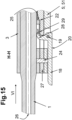
- Fig. 15-16 show possible embodiments in which the tensioning element 20 or the tensioning portion 28 are pretensioned by means of the spring element 29 under tensile stress.
- the spring element 29 in Fig. 15 can be arranged such that the intermediate piece 27 and therefore the locking bush 3 can be rigidly pretensioned with the upper 4 by means of the support 5, thereby ensuring a rigid and reproducible seat of the barrel 1.
- Fig. 16 indicates another variant in which the spring element 29 is arranged inside the tensioning element 20.
- pretension and a force are once again applied normally with respect to the barrel shaft 26 by the tensioning portion 28 in the closed position.
- clamping takes place in the axial direction similarly to in the above-mentioned examples.
- the invention can have various modifications and designs, in particular the proportions of the individual components described can be adapted to match the respective specifications of the gun.
- substantially means a deviation of up to 10 % of the stated value both downwards and upwards, if physically possible, and otherwise only in the sensible direction; for degrees (angles and temperatures), ⁇ 10° is therefore meant.
Landscapes
- Engineering & Computer Science (AREA)
- General Engineering & Computer Science (AREA)
- Clamps And Clips (AREA)
- Portable Nailing Machines And Staplers (AREA)
- Aiming, Guidance, Guns With A Light Source, Armor, Camouflage, And Targets (AREA)
- Mutual Connection Of Rods And Tubes (AREA)
Claims (14)
- Waffe, insbesondere Karabiner, mit einem Obergehäuse (4) und einem Untergehäuse (10), das Obergehäuse enthaltend zumindest einen Lauf (1) mit einer Laufachse (26), gegebenenfalls mit einer fest mit ihm verbundenen Verriegelungshülse (3), gegebenenfalls einen Träger (5), der mit dem Obergehäuse fest verbunden ist um einen Verschlussmechanismus (7) aufzunehmen, einen Verschlussmechanismus (7) einen Schlagbolzenmechanismus, gegebenenfalls einen Gasmechanismus (2) und eine Abdeckung, das Untergehäuse (10) enthaltend zumindest ein Griffstück (13), ein Magazin (16) und einen Abzugsmechanismus (12), wobei das Obergehäuse (4) und das Untergehäuse (10) im zusammengebauten, feuerbereiten Zustand miteinander verbunden sind und der Abzugsmechanismus (12) mit dem Schlagbolzenmechanismus in Wirkverbindung steht und wobei der Lauf (1) im Obergehäuse (4) lösbar angeordnet ist, dadurch gekennzeichnet, dass einerseits der Lauf (1), gegebenenfalls seine Verriegelungshülse (3), und das Obergehäuse (4), gegebenenfalls der Träger (5) durch einander entsprechende Führungen (6) im Obergehäuse, gegebenenfalls am Träger (5), und am Lauf, gegebenenfalls an der Verriegelungshülse (3) gegebenenfalls direkt am Obergehäuse (4), mittels einer Führung (6) miteinander verbunden sind, dass die Führungen (6), im montierten, feuerbereiten Zustand der Waffe, parallel zur Laufachse (26) verlaufende, prismatische Führungsflächen (23) aufweisen, dass die Fixierung des Laufes (1) am Obergehäuse (4) mittels eines im Obergehäuse um eine normal zur Waffenmittelebene verlaufende Drehachse (19) zwischen zwei Endlagen, der schussbereiten Position und der Zerlegeposition, verdrehbaren Spannelementes (20), mit einem Spannabschnitt (28), gegebenenfalls in Form einer Nocke, und einem Betätigungsabschnitts (18), erfolgt, und dass in der schussbereiten Position der Spannabschnitt (28) an einer Anschlagfläche des Laufes (1) bzw. seiner Verriegelungshülse (3) anliegt und in der Zerlegeposition der Spannabschnitt (28), gegebenenfalls die Nocke, zur Gänze außerhalb der Bewegungsbahn des Laufs (1), gegebenenfalls auch seiner Verriegelungshülse (3), liegt.
- Waffe nach Anspruch 1 dadurch gekennzeichnet, dass der Träger (5) oder gegebenenfalls der Upper (4) eine axiale Anschlagfläche (22) zur Abstützung der Verriegelungshülse (3) und/oder des Laufs (1) aufweist.
- Waffe, insbesondere Karabiner, nach Anspruch 1 oder 2, dadurch gekennzeichnet, dass die Führung (6) zumindest eine Schwalbenschwanzführung ist.
- Waffe nach einem der vorhergehenden Ansprüche dadurch gekennzeichnet, dass die Führung (6) zumindest zwei geteilte Zentrierelemente (21a, 21b) und damit zusammenwirkende Führungsflächen (23) umfasst.
- Waffe, insbesondere Karabiner, nach einem der vorhergehenden Ansprüche dadurch gekennzeichnet, dass in schussbereiter Position des Spannelementes (20), der Spannteil (28) gegebenenfalls die Nocke, auf den Lauf (1), gegebenenfalls seine Verriegelungshülse (3), eine Kraft ausübt, die in der Waffenmittelebene und normal zur Laufachse (26) orientiert ist.
- Waffe, insbesondere Karabiner nach einem der vorhergehenden Ansprüche, dadurch gekennzeichnet, dass die Führung (6) symmetrisch zur Waffenmittelebene vorgesehen ist.
- Waffe nach einem der vorhergehenden Ansprüche dadurch gekennzeichnet, dass der Lauf (1) an der Unterseite zur Aufnahme und Abstützung des Spannabschnitts (28) eine Abflachung aufweist.
- Waffe nach einem der vorhergehenden Ansprüche dadurch gekennzeichnet, dass der Lauf (1) an der Unterseite zur Aufnahme und Abstützung des Spannabschnittes (28) eine Ausnehmung aufweist, und dass die gegebenenfalls vorhandene Verriegelungshülse (3) an der Unterseite eine im Wesentlichen gleich große Durchtrittsöffnung für den Spannabschnitt (28) aufweist.
- Waffe nach einem der vorhergehenden Ansprüche dadurch gekennzeichnet, dass der Lauf (1) mit der Verriegelungshülse (3) lösbar verbunden, bevorzugt verschraubt, ist.
- Waffe nach einem der vorhergehenden Ansprüche dadurch gekennzeichnet, dass der Träger (5) einteilig mit dem Upper (4) ausgebildet ist.
- Waffe nach einem der vorhergehenden Ansprüche dadurch gekennzeichnet, dass der Spannabschnitt (28) als Nocke ausgebildet ist.
- Waffe nach einem der vorhergehenden Ansprüche dadurch gekennzeichnet, dass ein Federelement (29) derart angeordnet ist, dass der Betätigungsabschnitt (28) in geschlossenem Zustand mit einer Vorspannkraft im Wesentlichen normal zur Laufachse (26) bewegbar ist.
- Waffe nach Anspruch 12 dadurch gekennzeichnet, dass das Federelement (29) zwischen Lauf (1) und/oder Verriegelungshülse (3) und dem Spannabschnitt (28) angeordnet ist.
- Waffe nach Anspruch 12 dadurch gekennzeichnet, dass ein Federelement (29) im Wesentlichen innerhalb des Spannelements (20), bevorzugt innerhalb des Spannabschnitts (28) ausgebildet ist.
Priority Applications (14)
| Application Number | Priority Date | Filing Date | Title |
|---|---|---|---|
| EP19201455.3A EP3800434B1 (de) | 2019-10-04 | 2019-10-04 | Waffe, insbesondere ein karabiner |
| US17/026,027 US11333460B2 (en) | 2019-10-04 | 2020-09-18 | Firearm with improved barrel connection |
| PCT/EP2020/077084 WO2021063876A1 (de) | 2019-10-04 | 2020-09-28 | Laufeinheit für eine feuerwaffe |
| US17/754,449 US20220341696A1 (en) | 2019-10-04 | 2020-09-28 | Firearm with barrel clamp |
| CA3152033A CA3152033A1 (en) | 2019-10-04 | 2020-09-28 | Barrel unit for a firearm |
| CA3156638A CA3156638A1 (en) | 2019-10-04 | 2020-09-28 | FIREARM EQUIPPED WITH A TUBE CLAMPING DEVICE |
| EP20775879.8A EP4038337B1 (de) | 2019-10-04 | 2020-09-28 | Laufeinheit für eine feuerwaffe |
| BR112022003017A BR112022003017A2 (pt) | 2019-10-04 | 2020-09-28 | Unidade de cano para arma de fogo |
| EP20775681.8A EP4038336B1 (de) | 2019-10-04 | 2020-09-28 | Feuerwaffe mit einer vorrichtung zur laufklemmung |
| PCT/EP2020/077111 WO2021063891A1 (de) | 2019-10-04 | 2020-09-28 | Feuerwaffe mit einer vorrichtung zur laufklemmung |
| US17/753,945 US11841201B2 (en) | 2019-10-04 | 2020-09-28 | Barrel unit for a firearm |
| BR112022003239A BR112022003239A2 (pt) | 2019-10-04 | 2020-09-28 | Arma de fogo com um dispositivo para prender cano |
| IL290580A IL290580A (en) | 2019-10-04 | 2022-02-13 | Cartridge unit for firearms |
| IL290874A IL290874A (en) | 2019-10-04 | 2022-02-24 | Firearms with clamping to the barrel |
Applications Claiming Priority (1)
| Application Number | Priority Date | Filing Date | Title |
|---|---|---|---|
| EP19201455.3A EP3800434B1 (de) | 2019-10-04 | 2019-10-04 | Waffe, insbesondere ein karabiner |
Publications (3)
| Publication Number | Publication Date |
|---|---|
| EP3800434A1 EP3800434A1 (de) | 2021-04-07 |
| EP3800434B1 true EP3800434B1 (de) | 2023-11-01 |
| EP3800434C0 EP3800434C0 (de) | 2023-11-01 |
Family
ID=68158930
Family Applications (3)
| Application Number | Title | Priority Date | Filing Date |
|---|---|---|---|
| EP19201455.3A Active EP3800434B1 (de) | 2019-10-04 | 2019-10-04 | Waffe, insbesondere ein karabiner |
| EP20775681.8A Active EP4038336B1 (de) | 2019-10-04 | 2020-09-28 | Feuerwaffe mit einer vorrichtung zur laufklemmung |
| EP20775879.8A Active EP4038337B1 (de) | 2019-10-04 | 2020-09-28 | Laufeinheit für eine feuerwaffe |
Family Applications After (2)
| Application Number | Title | Priority Date | Filing Date |
|---|---|---|---|
| EP20775681.8A Active EP4038336B1 (de) | 2019-10-04 | 2020-09-28 | Feuerwaffe mit einer vorrichtung zur laufklemmung |
| EP20775879.8A Active EP4038337B1 (de) | 2019-10-04 | 2020-09-28 | Laufeinheit für eine feuerwaffe |
Country Status (6)
| Country | Link |
|---|---|
| US (3) | US11333460B2 (de) |
| EP (3) | EP3800434B1 (de) |
| BR (2) | BR112022003017A2 (de) |
| CA (2) | CA3152033A1 (de) |
| IL (2) | IL290580A (de) |
| WO (2) | WO2021063891A1 (de) |
Families Citing this family (3)
| Publication number | Priority date | Publication date | Assignee | Title |
|---|---|---|---|---|
| EP3800434B1 (de) * | 2019-10-04 | 2023-11-01 | Glock Technology GmbH | Waffe, insbesondere ein karabiner |
| US11598600B2 (en) * | 2021-01-28 | 2023-03-07 | Robert W. Landies, III | Quick-change barrel for a firearm |
| EP4194795A1 (de) | 2021-12-10 | 2023-06-14 | Glock Technology GmbH | Vorrichtung zur ausbildung einer sekundären befestigung eines vorderschafts |
Family Cites Families (39)
| Publication number | Priority date | Publication date | Assignee | Title |
|---|---|---|---|---|
| FR9820E (de) | 1908-01-29 | |||
| FR412523A (fr) * | 1909-05-03 | 1910-07-15 | Mimard Soc | Pistolet à répétition semi-automatique |
| DE303873C (de) * | 1921-01-03 | |||
| GB268996A (en) * | 1926-05-28 | 1927-04-14 | William Beardmore & Company Lt | Improvements in or relating to mountain howitzers and the like |
| US2455608A (en) * | 1945-08-31 | 1948-12-07 | Orvar E Rosengren | Barrel lock |
| US2817174A (en) * | 1954-08-17 | 1957-12-24 | High Standard Mfg Corp | Take-down device for firearms |
| GB1200848A (en) * | 1967-07-31 | 1970-08-05 | Brevets Aero Mecaniques | Improvements in/or relating to semi-automatic and automatic fire-arms |
| IL92039A0 (en) * | 1989-10-18 | 1990-07-12 | Israel State | Locking mechanism for machine gun barrel |
| US5410834A (en) * | 1993-08-05 | 1995-05-02 | Michael Edward Benton | Rifle with interchangeable barrel |
| DE19815261C2 (de) * | 1998-04-06 | 2000-03-30 | Manfred Orth | Zusammensetzbare Handfeuerwaffe |
| US6487805B1 (en) * | 2000-05-19 | 2002-12-03 | Armalite, Inc. | Firearm assembly |
| US6470617B1 (en) * | 2001-10-31 | 2002-10-29 | Thomas M. Gregory | Folding stock |
| FR2837275B1 (fr) * | 2002-03-14 | 2004-06-25 | Chapuis Armes | Carabine a canon amovible |
| EP1574806B1 (de) * | 2004-03-11 | 2011-02-09 | Voere Holding GmbH | Gewehr |
| WO2006086003A2 (en) | 2004-07-27 | 2006-08-17 | Leitner-Wise Rifle Company, Inc. | Modular receiver system |
| DE102005037131B3 (de) * | 2005-08-06 | 2006-12-14 | Rheinmetall Waffe Munition Gmbh | Vorrichtung zum Verbinden und Verriegeln eines Verschlusses und/oder eines Laufes einer Waffe |
| DE102006022622A1 (de) * | 2006-05-12 | 2007-11-15 | Rheinmetall Waffe Munition Gmbh | Funktionssteuerung insbesondere für das lineare Zuführen einer Munition in ein Waffenrohr |
| US7673553B2 (en) * | 2007-05-21 | 2010-03-09 | Karl Lippard | Barrel link for a semiautomatic weapon |
| US7841121B1 (en) | 2008-01-09 | 2010-11-30 | Browning | Takedown rifle |
| DE102009051416A1 (de) | 2008-10-30 | 2010-07-22 | Christian Scherpf | Langwaffe |
| US7823314B1 (en) * | 2008-12-02 | 2010-11-02 | Wheatley Craig A | Firearm with a detachable barrel and suppressed barrel assembly |
| US8087194B1 (en) * | 2009-03-24 | 2012-01-03 | Sturm, Ruger & Company, Inc. | Firearm barrel retaining system |
| DE102010000617B4 (de) | 2010-03-03 | 2012-02-23 | Al Hail Holding Llc | Repetiergewehr mit austauschbarer Lauf-Verschlussgruppe |
| US8973483B2 (en) | 2010-03-25 | 2015-03-10 | Arm West, Llc | Gas regulator system |
| US8739446B2 (en) | 2010-03-25 | 2014-06-03 | ArmWest, LLC | High capacity magazine with multiple springs |
| US9228786B2 (en) | 2011-01-14 | 2016-01-05 | ArmWest, LLC | Quick barrel change firearm |
| US9038525B2 (en) | 2011-01-14 | 2015-05-26 | ArmWest, LLC | Firearm |
| US9488423B2 (en) | 2011-01-14 | 2016-11-08 | Arm West, Llc | Firearm systems and methods |
| DE202011100433U1 (de) * | 2011-05-07 | 2011-08-22 | Karl-Heinz Walz | Zerlegbares Gewehr |
| DE102011114686B3 (de) | 2011-10-04 | 2013-03-07 | J.P. Sauer & Sohn Gmbh | Handfeuerwaffe mit einer Laufaufnahme |
| US8881444B2 (en) * | 2011-12-14 | 2014-11-11 | Sturm, Ruger & Company, Inc. | Stock bedding system for firearm |
| DE202012101602U1 (de) | 2012-04-30 | 2012-06-12 | Liemke Gmbh & Co. Kg | Zerlegbare Schusswaffe |
| US9383154B2 (en) * | 2013-12-12 | 2016-07-05 | Ra Brands, L.L.C. | Gas vent for firearm |
| US20150308779A1 (en) | 2013-12-23 | 2015-10-29 | S. I. Defense, Inc. | Quick-release barrel firearm |
| AT14107U1 (de) | 2014-02-27 | 2015-04-15 | Strasser Herbert | Laufhalterung für eine Schusswaffe |
| SK288780B6 (sk) * | 2016-12-21 | 2020-10-02 | Michut Viktor | Uzamykací systém puzdra ručnej strelnej zbrane |
| US11137226B2 (en) * | 2019-02-21 | 2021-10-05 | Andrew Bennink | Multi-caliber weapon system and components |
| EP3800434B1 (de) * | 2019-10-04 | 2023-11-01 | Glock Technology GmbH | Waffe, insbesondere ein karabiner |
| US11326853B2 (en) * | 2020-01-07 | 2022-05-10 | Brendon Zinsner | Free-floating rifle rail and barrel locking system(s)/assemblies |
-
2019
- 2019-10-04 EP EP19201455.3A patent/EP3800434B1/de active Active
-
2020
- 2020-09-18 US US17/026,027 patent/US11333460B2/en active Active
- 2020-09-28 WO PCT/EP2020/077111 patent/WO2021063891A1/de active Application Filing
- 2020-09-28 CA CA3152033A patent/CA3152033A1/en active Pending
- 2020-09-28 WO PCT/EP2020/077084 patent/WO2021063876A1/de unknown
- 2020-09-28 EP EP20775681.8A patent/EP4038336B1/de active Active
- 2020-09-28 EP EP20775879.8A patent/EP4038337B1/de active Active
- 2020-09-28 US US17/753,945 patent/US11841201B2/en active Active
- 2020-09-28 BR BR112022003017A patent/BR112022003017A2/pt unknown
- 2020-09-28 BR BR112022003239A patent/BR112022003239A2/pt unknown
- 2020-09-28 US US17/754,449 patent/US20220341696A1/en active Pending
- 2020-09-28 CA CA3156638A patent/CA3156638A1/en active Pending
-
2022
- 2022-02-13 IL IL290580A patent/IL290580A/en unknown
- 2022-02-24 IL IL290874A patent/IL290874A/en unknown
Also Published As
| Publication number | Publication date |
|---|---|
| IL290580A (en) | 2022-04-01 |
| CA3156638A1 (en) | 2021-04-08 |
| US11333460B2 (en) | 2022-05-17 |
| US20210164750A1 (en) | 2021-06-03 |
| US20220341696A1 (en) | 2022-10-27 |
| IL290874A (en) | 2022-04-01 |
| US20220341695A1 (en) | 2022-10-27 |
| EP4038337C0 (de) | 2023-12-27 |
| US11841201B2 (en) | 2023-12-12 |
| WO2021063891A1 (de) | 2021-04-08 |
| BR112022003239A2 (pt) | 2022-07-19 |
| WO2021063876A1 (de) | 2021-04-08 |
| BR112022003017A2 (pt) | 2022-06-28 |
| EP4038337A1 (de) | 2022-08-10 |
| EP3800434A1 (de) | 2021-04-07 |
| EP4038336C0 (de) | 2023-12-27 |
| CA3152033A1 (en) | 2021-04-08 |
| EP4038337B1 (de) | 2023-12-27 |
| EP4038336B1 (de) | 2023-12-27 |
| EP3800434C0 (de) | 2023-11-01 |
| EP4038336A1 (de) | 2022-08-10 |
Similar Documents
| Publication | Publication Date | Title |
|---|---|---|
| US11333460B2 (en) | Firearm with improved barrel connection | |
| EP2017564B1 (de) | Tragbare Modularwaffe | |
| US9562731B2 (en) | Method for manufacturing a trigger element of a sear mechanism for a firearm | |
| US8539708B2 (en) | Barrel mounting and retention mechanism | |
| US5410834A (en) | Rifle with interchangeable barrel | |
| US9869531B1 (en) | Integrated optical sight mount | |
| US20180058788A1 (en) | Firearm with safe axis firing pin and center aligned barrel | |
| US20050235546A1 (en) | Firearm, in particular a self-loading small-caliber rifle | |
| US10209019B2 (en) | Pistol | |
| US10969184B2 (en) | Bolt action firearm receiver assemblies | |
| CA2417109C (en) | Weapon system | |
| US6470616B1 (en) | Combination barrel adjustment and magazine cutoff for a takedown firearm | |
| US10794648B2 (en) | Magazine release and holding apparatus for use with firearms | |
| US20220003512A1 (en) | Roller and bearing delayed firearm operating systems | |
| US9593896B2 (en) | Bolt rifle assembly | |
| US20210207904A1 (en) | Gas-powered firearm | |
| BR112020004260B1 (pt) | Metralhadora | |
| US7574951B2 (en) | Single-shot rifle | |
| US11530894B2 (en) | Pistol having a rigid barrel, in particular training weapon | |
| US20230138874A1 (en) | Recoil spring abutment for a slide of a modular handgun | |
| EP2053336B1 (de) | Einzelladergewehr | |
| US20220412678A1 (en) | Breech for a pistol | |
| JP2005016907A (ja) | ライフル銃及び散弾銃の薬室装填給弾機構 | |
| BR102013014433A2 (pt) | fuzil de assalto aperfeiÇoado |
Legal Events
| Date | Code | Title | Description |
|---|---|---|---|
| PUAI | Public reference made under article 153(3) epc to a published international application that has entered the european phase |
Free format text: ORIGINAL CODE: 0009012 |
|
| STAA | Information on the status of an ep patent application or granted ep patent |
Free format text: STATUS: THE APPLICATION HAS BEEN PUBLISHED |
|
| AK | Designated contracting states |
Kind code of ref document: A1 Designated state(s): AL AT BE BG CH CY CZ DE DK EE ES FI FR GB GR HR HU IE IS IT LI LT LU LV MC MK MT NL NO PL PT RO RS SE SI SK SM TR |
|
| AX | Request for extension of the european patent |
Extension state: BA ME |
|
| STAA | Information on the status of an ep patent application or granted ep patent |
Free format text: STATUS: REQUEST FOR EXAMINATION WAS MADE |
|
| 17P | Request for examination filed |
Effective date: 20211001 |
|
| RBV | Designated contracting states (corrected) |
Designated state(s): AL AT BE BG CH CY CZ DE DK EE ES FI FR GB GR HR HU IE IS IT LI LT LU LV MC MK MT NL NO PL PT RO RS SE SI SK SM TR |
|
| STAA | Information on the status of an ep patent application or granted ep patent |
Free format text: STATUS: EXAMINATION IS IN PROGRESS |
|
| 17Q | First examination report despatched |
Effective date: 20230118 |
|
| GRAJ | Information related to disapproval of communication of intention to grant by the applicant or resumption of examination proceedings by the epo deleted |
Free format text: ORIGINAL CODE: EPIDOSDIGR1 |
|
| STAA | Information on the status of an ep patent application or granted ep patent |
Free format text: STATUS: GRANT OF PATENT IS INTENDED |
|
| GRAP | Despatch of communication of intention to grant a patent |
Free format text: ORIGINAL CODE: EPIDOSNIGR1 |
|
| INTG | Intention to grant announced |
Effective date: 20230720 |
|
| GRAS | Grant fee paid |
Free format text: ORIGINAL CODE: EPIDOSNIGR3 |
|
| GRAA | (expected) grant |
Free format text: ORIGINAL CODE: 0009210 |
|
| STAA | Information on the status of an ep patent application or granted ep patent |
Free format text: STATUS: THE PATENT HAS BEEN GRANTED |
|
| AK | Designated contracting states |
Kind code of ref document: B1 Designated state(s): AL AT BE BG CH CY CZ DE DK EE ES FI FR GB GR HR HU IE IS IT LI LT LU LV MC MK MT NL NO PL PT RO RS SE SI SK SM TR |
|
| REG | Reference to a national code |
Ref country code: GB Ref legal event code: FG4D |
|
| REG | Reference to a national code |
Ref country code: CH Ref legal event code: EP |
|
| REG | Reference to a national code |
Ref country code: DE Ref legal event code: R096 Ref document number: 602019040475 Country of ref document: DE |
|
| REG | Reference to a national code |
Ref country code: IE Ref legal event code: FG4D |
|
| U01 | Request for unitary effect filed |
Effective date: 20231116 |
|
| U07 | Unitary effect registered |
Designated state(s): AT BE BG DE DK EE FI FR IT LT LU LV MT NL PT SE SI Effective date: 20231122 |
|
| PG25 | Lapsed in a contracting state [announced via postgrant information from national office to epo] |
Ref country code: GR Free format text: LAPSE BECAUSE OF FAILURE TO SUBMIT A TRANSLATION OF THE DESCRIPTION OR TO PAY THE FEE WITHIN THE PRESCRIBED TIME-LIMIT Effective date: 20240202 |
|
| PG25 | Lapsed in a contracting state [announced via postgrant information from national office to epo] |
Ref country code: IS Free format text: LAPSE BECAUSE OF FAILURE TO SUBMIT A TRANSLATION OF THE DESCRIPTION OR TO PAY THE FEE WITHIN THE PRESCRIBED TIME-LIMIT Effective date: 20240301 |
|
| PG25 | Lapsed in a contracting state [announced via postgrant information from national office to epo] |
Ref country code: ES Free format text: LAPSE BECAUSE OF FAILURE TO SUBMIT A TRANSLATION OF THE DESCRIPTION OR TO PAY THE FEE WITHIN THE PRESCRIBED TIME-LIMIT Effective date: 20231101 |
|
| PG25 | Lapsed in a contracting state [announced via postgrant information from national office to epo] |
Ref country code: IS Free format text: LAPSE BECAUSE OF FAILURE TO SUBMIT A TRANSLATION OF THE DESCRIPTION OR TO PAY THE FEE WITHIN THE PRESCRIBED TIME-LIMIT Effective date: 20240301 Ref country code: GR Free format text: LAPSE BECAUSE OF FAILURE TO SUBMIT A TRANSLATION OF THE DESCRIPTION OR TO PAY THE FEE WITHIN THE PRESCRIBED TIME-LIMIT Effective date: 20240202 Ref country code: ES Free format text: LAPSE BECAUSE OF FAILURE TO SUBMIT A TRANSLATION OF THE DESCRIPTION OR TO PAY THE FEE WITHIN THE PRESCRIBED TIME-LIMIT Effective date: 20231101 |