EP3799397B1 - Procédé de mise à jour du système de stockage d'énergie à distance, système de gestion de l'énergie, et système de gestion de batterie - Google Patents
Procédé de mise à jour du système de stockage d'énergie à distance, système de gestion de l'énergie, et système de gestion de batterie Download PDFInfo
- Publication number
- EP3799397B1 EP3799397B1 EP20769922.4A EP20769922A EP3799397B1 EP 3799397 B1 EP3799397 B1 EP 3799397B1 EP 20769922 A EP20769922 A EP 20769922A EP 3799397 B1 EP3799397 B1 EP 3799397B1
- Authority
- EP
- European Patent Office
- Prior art keywords
- energy storage
- upgraded
- storage system
- upgrade
- management system
- Prior art date
- Legal status (The legal status is an assumption and is not a legal conclusion. Google has not performed a legal analysis and makes no representation as to the accuracy of the status listed.)
- Active
Links
Images

Classifications
-
- H—ELECTRICITY
- H04—ELECTRIC COMMUNICATION TECHNIQUE
- H04L—TRANSMISSION OF DIGITAL INFORMATION, e.g. TELEGRAPHIC COMMUNICATION
- H04L67/00—Network arrangements or protocols for supporting network services or applications
- H04L67/01—Protocols
- H04L67/02—Protocols based on web technology, e.g. hypertext transfer protocol [HTTP]
- H04L67/025—Protocols based on web technology, e.g. hypertext transfer protocol [HTTP] for remote control or remote monitoring of applications
-
- G—PHYSICS
- G06—COMPUTING OR CALCULATING; COUNTING
- G06F—ELECTRIC DIGITAL DATA PROCESSING
- G06F1/00—Details not covered by groups G06F3/00 - G06F13/00 and G06F21/00
- G06F1/26—Power supply means, e.g. regulation thereof
- G06F1/28—Supervision thereof, e.g. detecting power-supply failure by out of limits supervision
-
- G—PHYSICS
- G06—COMPUTING OR CALCULATING; COUNTING
- G06F—ELECTRIC DIGITAL DATA PROCESSING
- G06F11/00—Error detection; Error correction; Monitoring
- G06F11/07—Responding to the occurrence of a fault, e.g. fault tolerance
- G06F11/14—Error detection or correction of the data by redundancy in operations
- G06F11/1402—Saving, restoring, recovering or retrying
- G06F11/1415—Saving, restoring, recovering or retrying at system level
- G06F11/1433—Saving, restoring, recovering or retrying at system level during software upgrading
-
- G—PHYSICS
- G06—COMPUTING OR CALCULATING; COUNTING
- G06F—ELECTRIC DIGITAL DATA PROCESSING
- G06F8/00—Arrangements for software engineering
- G06F8/60—Software deployment
- G06F8/65—Updates
-
- H—ELECTRICITY
- H02—GENERATION; CONVERSION OR DISTRIBUTION OF ELECTRIC POWER
- H02J—ELECTRIC POWER NETWORKS; CIRCUIT ARRANGEMENTS OR SYSTEMS FOR SUPPLYING OR DISTRIBUTING ELECTRIC POWER; SYSTEMS FOR STORING ELECTRIC ENERGY
- H02J15/00—Systems for storing electric energy specially adapted for power networks
-
- H—ELECTRICITY
- H02—GENERATION; CONVERSION OR DISTRIBUTION OF ELECTRIC POWER
- H02J—ELECTRIC POWER NETWORKS; CIRCUIT ARRANGEMENTS OR SYSTEMS FOR SUPPLYING OR DISTRIBUTING ELECTRIC POWER; SYSTEMS FOR STORING ELECTRIC ENERGY
- H02J7/00—Circuit arrangements for charging or discharging batteries or for supplying loads from batteries
- H02J7/60—Circuit arrangements for charging or discharging batteries or for supplying loads from batteries including safety or protection arrangements
-
- H—ELECTRICITY
- H04—ELECTRIC COMMUNICATION TECHNIQUE
- H04L—TRANSMISSION OF DIGITAL INFORMATION, e.g. TELEGRAPHIC COMMUNICATION
- H04L67/00—Network arrangements or protocols for supporting network services or applications
- H04L67/01—Protocols
- H04L67/12—Protocols specially adapted for proprietary or special-purpose networking environments, e.g. medical networks, sensor networks, networks in vehicles or remote metering networks
-
- H—ELECTRICITY
- H04—ELECTRIC COMMUNICATION TECHNIQUE
- H04L—TRANSMISSION OF DIGITAL INFORMATION, e.g. TELEGRAPHIC COMMUNICATION
- H04L67/00—Network arrangements or protocols for supporting network services or applications
- H04L67/34—Network arrangements or protocols for supporting network services or applications involving the movement of software or configuration parameters
-
- H—ELECTRICITY
- H04—ELECTRIC COMMUNICATION TECHNIQUE
- H04L—TRANSMISSION OF DIGITAL INFORMATION, e.g. TELEGRAPHIC COMMUNICATION
- H04L67/00—Network arrangements or protocols for supporting network services or applications
- H04L67/50—Network services
- H04L67/55—Push-based network services
-
- H—ELECTRICITY
- H04—ELECTRIC COMMUNICATION TECHNIQUE
- H04L—TRANSMISSION OF DIGITAL INFORMATION, e.g. TELEGRAPHIC COMMUNICATION
- H04L67/00—Network arrangements or protocols for supporting network services or applications
- H04L67/50—Network services
- H04L67/56—Provisioning of proxy services
- H04L67/562—Brokering proxy services
-
- G—PHYSICS
- G06—COMPUTING OR CALCULATING; COUNTING
- G06F—ELECTRIC DIGITAL DATA PROCESSING
- G06F2201/00—Indexing scheme relating to error detection, to error correction, and to monitoring
- G06F2201/865—Monitoring of software
-
- Y—GENERAL TAGGING OF NEW TECHNOLOGICAL DEVELOPMENTS; GENERAL TAGGING OF CROSS-SECTIONAL TECHNOLOGIES SPANNING OVER SEVERAL SECTIONS OF THE IPC; TECHNICAL SUBJECTS COVERED BY FORMER USPC CROSS-REFERENCE ART COLLECTIONS [XRACs] AND DIGESTS
- Y02—TECHNOLOGIES OR APPLICATIONS FOR MITIGATION OR ADAPTATION AGAINST CLIMATE CHANGE
- Y02D—CLIMATE CHANGE MITIGATION TECHNOLOGIES IN INFORMATION AND COMMUNICATION TECHNOLOGIES [ICT], I.E. INFORMATION AND COMMUNICATION TECHNOLOGIES AIMING AT THE REDUCTION OF THEIR OWN ENERGY USE
- Y02D10/00—Energy efficient computing, e.g. low power processors, power management or thermal management
Definitions
- This application relates to the technical field of batteries, and in particular, to a method for upgrading an energy storage system remotely as specified in claim 1, a communications gateway as specified in claim 2, a battery management system as specified in claim 3, an energy management system as specified in claim 4, and a remote upgrade system as specified in claim 5 .
- a battery management system (battery management system, hereinafter referred to as "BMS") is a link between a battery and a user, and can improve the utilization rate of the battery, prevent the battery from overcharge and over discharge, extend the battery life, and monitor the battery status.
- BMS battery management system
- CN 109 066 926 A describes a system for monitoring and upgrading a battery management system BMS based on Android platform.
- the system comprises: a power management system, an industrial control screen and a remote monitoring platform. Through the Android industrial control screen to display the battery pack voltage, current, temperature, status and other information currently obtained by BMS.
- the Android industrial control screen is connected to the Internet, and the BMS acquisition parameters are uploaded through an API provided by the remote monitoring platform through a monitoring APP, and the commands sent by the monitoring platform are received to control the related actions of the BMS, so as to realize the remote monitoring.
- BMS can also be remotely upgraded to facilitate later use and maintenance.
- CN 105 491 161 A describes a battery management system software remote upgrading system comprising a server system, client sides and multiple battery management systems. The client sides transmit received user selection operation to the server system. The battery management systems are used for uploading heartbeat information to the server system and completing system software upgrading according to received upgrading files.
- the heartbeat information includes current version information and current state information.
- the server system is used for issuing the corresponding upgrading files to the corresponding battery management systems when the heartbeat information meets the issuing conditions through judgment. Pausing or resuming is selected in the issuing process according to feedback state information until completion of transmission.
- CN 108 874 430 A describes an ECU (electronic controller unit) upgrading method and device and a battery management system.
- the method applied to the battery management system includes receiving upgrade data; determining an ECU that the upgrade data points at; controlling the ECU that the upgrade data points at to upgrade according to the upgrade data.
- Embodiments of this application provide a method for upgrading an energy storage system remotely, an energy management system, and a battery management system to implement remote program upgrade of the energy storage system, simplify upgrade operations of the energy storage system, and save costs of human resources and time.
- the same line can be shared by upgrade and communication, thereby saving hardware costs.
- the energy storage system includes an energy management system (Energy Management System, hereinafter referred to as "EMS"), a BMS, and a power conversion system (Power Conversion System, hereinafter referred to as "PCS").
- EMS Energy Management System
- BMS Battery Management System
- PCS Power Conversion System
- the EMS controls, by using the PCS, the energy storage system to disconnect from high voltage; detects the status of high voltage connection of the energy storage system by using the BMS; and sends the to-be-upgraded file to the BMS after receiving the notification sent by the BMS about completion of disconnecting the energy storage system from high voltage, so that the BMS performs the program upgrade according to the to-be-upgraded file.
- the program upgrade can be performed for the energy storage system remotely, the upgrade operation of the energy storage system is simplified, and costs of human resources and time are saved.
- the same line can be shared by upgrade and communication, thereby further saving hardware costs.
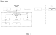
- FIG. 1 is a schematic diagram of a communications architecture of an energy storage system according to this application.
- the communications architecture of the energy storage system includes a client, a server, and an energy storage system.
- the communication means for remote communication between the client and the energy storage system may be, but without limitation, Ethernet. Nevertheless, other communications means available for remote communication may also be included.
- the communication means between different energy storage systems may be, but without limitation, a wireless network or a controller area network (controller area network, hereinafter referred to as "CAN"). Nevertheless, other communication means may also be adopted.
- CAN controller area network
- circumstances in which an energy storage system is upgraded remotely may include the following circumstances:
- an embodiment of this application discloses a method for upgrading an energy storage system remotely.
- the method is applied to an energy storage system.
- the energy storage system may include an EMS, a BMS, and a PCS.
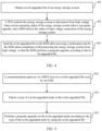
- FIG. 4 is a flowchart of an embodiment of the method for upgrading an energy storage system remotely according to this application.
- the method for upgrading an energy storage system remotely according to this embodiment may be implemented by the EMS.
- the method for upgrading an energy storage system remotely may include the following steps.
- Step 401 Obtain a to-be-upgraded file of the energy storage system.
- the obtaining a to-be-upgraded file of the energy storage system may be: receiving the to-be-upgraded file of the energy storage system sent by a server, where the to-be-upgraded file of the energy storage system is sent by the server after the to-be-upgraded file uploaded by a client is received, and the to-be-upgraded file uploaded by a client is an encrypted to-be-upgraded file that is uploaded by the client to the server after the client performs format adjustment and/or data encryption on the to-be-upgraded file of the energy storage system; or
- the client after performing format adjustment and/or data encryption on the to-be-upgraded file of the energy storage system, the client uploads the encrypted file to the server through a network. After detecting the to-be-upgraded file uploaded by the client, the server notifies the EMS that a file needs to be upgraded, and sends the to-be-upgraded file to the EMS.
- the EMS may query the server about a version of the to-be-upgraded file in the server at a preset time or periodically, and obtain an updated to-be-upgraded file from the server if it is detected that the version of the to-be-upgraded file in the server is an updated version.
- the EMS may also obtain the to-be-upgraded file of the energy storage system from the memory connected to the EMS.
- the to-be-upgraded file of the energy storage system may be stored in the memory, and then the memory is connected to the EMS.
- the EMS can obtain the to-be-upgraded file of the energy storage system from the connected memory.
- the memory may be a device capable of storage, such as a USB flash disk or a mobile hard disk. This embodiment does not limit the form of the memory.
- Step 402 The PCS controls the energy storage system to disconnect from high voltage when current operating status of the energy storage system allows a program upgrade, and the BMS detects the status of high voltage connection of the energy storage system.
- the EMS needs to determine whether the current operating status of the energy storage system allows a program upgrade. If the energy storage system is currently in a working state such as a high-power output state, the program upgrade is not allowed. If the energy storage system is currently in a non-working state such as a static standing state, the program upgrade is allowed.
- the EMS controls, by using the PCS, the energy storage system to disconnect from high voltage, and detects the status of high voltage connection of the energy storage system by using the BMS.
- Step 403 Send the to-be-upgraded file to the BMS after receiving a notification sent by the BMS about completion of disconnecting the energy storage system from high voltage, so that the BMS performs the program upgrade according to the to-be-upgraded file.
- the BMS detects the status of high voltage disconnection of the energy storage system and, if it is detected that the energy storage system is disconnected from high voltage, sends a notification to the EMS about completion of disconnecting the energy storage system from high voltage.
- the EMS may send the to-be-upgraded file to the BMS according to an established communications protocol, so that the BMS performs the program upgrade according to the to-be-upgraded file.
- the sending the to-be-upgraded file to the BMS so that the BMS performs the program upgrade according to the to-be-upgraded file may be: detecting a type of a to-be-upgraded node in the to-be-upgraded file; obtaining, from the to-be-upgraded file, upgrade data corresponding to the type of the to-be-upgraded node; and sending the upgrade data corresponding to the type of the to-be-upgraded node to a communications gateway in the BMS, so that the communications gateway sends the upgrade data corresponding to the type of the to-be-upgraded node to a corresponding to-be-upgraded node to complete the program upgrade for the corresponding to-be-upgraded node.
- the EMS may parse the to-be-upgraded file, detect the type of the to-be-upgraded node in the to-be-upgraded file, split the to-be-upgraded file, and obtain, from the to-be-upgraded file, the upgrade data corresponding to the type of the to-be-upgraded node; finally, send the obtained upgrade data to the communications gateway in the BMS, so that the communications gateway sends the upgrade data to the corresponding to-be-upgraded node to complete the program upgrade for the corresponding to-be-upgraded node.
- the EMS controls, by using the PCS, the energy storage system to disconnect from high voltage; detects the status of high voltage connection of the energy storage system by using the BMS; and sends the to-be-upgraded file to the BMS after receiving the notification sent by the BMS about completion of disconnecting the energy storage system from high voltage, so that the BMS performs the program upgrade according to the to-be-upgraded file.
- the program upgrade can be performed for the energy storage system remotely, the upgrade operation of the energy storage system is simplified, and costs of human resources and time are saved.
- the same line can be shared by upgrade and communication, thereby further saving hardware costs.
- FIG. 5 is a flowchart of another embodiment of a method for upgrading an energy storage system remotely according to this application.
- the method for upgrading an energy storage system remotely according to this embodiment may be implemented by a BMS.
- the method for upgrading an energy storage system remotely may include the following steps.
- Step 501 A communications gateway in the BMS receives a to-be-upgraded file sent by an EMS.
- the to-be-upgraded file is obtained by the EMS.
- the EMS controls the energy storage system to disconnect from high voltage when current operating status of the energy storage system allows a program upgrade, and detects status of high voltage connection of the energy storage system by using the BMS.
- the EMS sends the to-be-upgraded file to the BMS after receiving a notification sent by the BMS about completion of disconnecting the energy storage system from high voltage.
- Step 502 Detect a type of a to-be-upgraded node in the to-be-upgraded file.
- the communications gateway in the BMS may perform one or more of the following operations on the received to-be-upgraded file: decryption, decompression, verification, and storage.
- the verification may include an integrity check. Nevertheless, this embodiment is not limited to the integrity check.
- the verification may also include other types of checks, such as a legality check. This embodiment does not limit the type of the verification.
- the communications gateway may detect the type of the to-be-upgraded node in the to-be-upgraded file.
- Step 503 Perform the program upgrade on the to-be-upgraded node according to the type of the to-be-upgraded node by using the to-be-upgraded file.
- the type of the to-be-upgraded node is indicated in the to-be-upgraded file.
- the upgrade mode varies with the type of the to-be-upgraded node.
- the type of the to-be-upgraded node may be a communications gateway.
- the performing the program upgrade on the to-be-upgraded node according to the type of the to-be-upgraded node by using the to-be-upgraded file may be: setting an update flag bit in a non-volatile memory of the communications gateway; after an upgrade request included in the to-be-upgraded file to upgrade the communications gateway is detected, copying upgrade data in the to-be-upgraded file to a designated area of the communications gateway, such as an application (application, hereinafter referred to as "APP") running area in the communications gateway; verifying the upgrade data in the designated area after completion of copying the upgrade data; and running the upgrade data in the designated area of the communications gateway after the upgrade data in the designated area passes the verification, so as to complete the program upgrade of the communications gateway.
- APP application
- the communications gateway may set an update flag bit in a non-volatile memory (non-volatile memory, hereinafter referred to as "NVM"), and then start a program upgrade process (that is, jump to run a boot program).
- NVM non-volatile memory
- the boot program detects that an upgrade request exists currently, and therefore, copies the upgrade data, which is stored in a backup area of the communications gateway, to a designated area (such as an APP running area) of the communications gateway in an established file format.
- the boot program verifies the data in the designated area after completion of copying the upgrade data. After the upgrade data passes the verification, the resetting application is verified valid, and the upgrade data is run in the designated area of the communications gateway, so as to complete the program upgrade for the communications gateway.
- the type of the to-be-upgraded node may include a battery management unit and/or an IMM in the BMS.
- the battery management unit in the BMS may include: a slave battery management unit (slave battery management unit, hereinafter referred to as "SBMU") and a master battery management unit (master battery management unit, hereinafter referred to as "MBMU").
- SBMU slave battery management unit
- MBMU master battery management unit
- the performing the program upgrade on the to-be-upgraded node according to the type of the to-be-upgraded node by using the to-be-upgraded file may be: sending a program update notification to the battery management unit and/or the IMM; obtaining upgrade data from the to-be-upgraded file after a program upgrade process of the battery management unit and/or the IMM is started, and sending the upgrade data to the battery management unit and/or the IMM, so that the battery management unit and/or the IMM verifies the upgrade data and stores the upgrade data into a designated area in the battery management unit and/or the IMM after the upgrade data passes the verification, so as to complete the program upgrade for the battery management unit and/or the IMM.
- the communications gateway detects that the type of the to-be-upgraded node is SBMU, MBMU, or IMM, firstly the communications gateway instructs the SBMU, MBMU, or IMM to upgrade the program, and the SBMU, MBMU, or IMM jumps to run a boot program to start a program upgrade process.
- the communications gateway may directly send the upgrade data, which is obtained from the to-be-upgraded file, to the SBMU, MBMU, or IMM according to an established upgrade policy and in an established communications format.
- the boot program of the SBMU, MBMU, or IMM verifies the received upgrade data and, after the upgrade data passes the verification, stores the upgrade data into a designated area to complete the program upgrade for the SBMU, MBMU, or IMM.
- the type of the to-be-upgraded node may be a cell supervision circuit (cell supervision circuit, hereinafter referred to as "CSC") and/or a CSU in the BMS.
- the performing the program upgrade on the to-be-upgraded node according to the type of the to-be-upgraded node by using the to-be-upgraded file may be: sending a program upgrade notification to the CSC and/or the CSU; obtaining upgrade data from the to-be-upgraded file after a program upgrade process of the CSC and/or the CSU is started, and sending the upgrade data to the CSC and/or the CSU through a battery management unit, so that the CSC and/or the CSU verifies the upgrade data and stores the upgrade data into a designated area in the CSC and/or the CSU after the upgrade data passes the verification, so as to complete the program upgrade for the CSC and/or the CSU.
- the communications gateway detects that the type of the to-be-upgraded node is CSC or CSU, firstly the communications gateway instructs the CSC or CSU to upgrade the program, and the CSC or CSU jumps to run a boot program to start a program upgrade process. Secondly, the communications gateway sends the upgrade data, which is obtained from the to-be-upgraded file, to the SBMU according to an established upgrade policy and in an established communications format. The SBMU forwards the upgrade data to the CSC or CSU. The boot program of the CSC or CSU verifies the received upgrade data and, after the upgrade data passes the verification, stores the upgrade data into a designated area in the CSC or CSU to complete the program upgrade for the CSC or CSU.
- the communications gateway corrects the error according to an error type of the error, and restarts to perform a new process of program upgrade if the error fails to be corrected.
- the communications gateway stops the program upgrade process and reports a program upgrade failure notification to the EMS.
- the communications gateway may correct the error by means of packet retransmission.
- the preset threshold of the quantity of restarts may be set according to system performance and/or implementation requirements and the like in a specific implementation. This embodiment does not limit the threshold.
- the threshold may be 5.
- the type of the to-be-upgraded node may include a battery management unit, an IMM, and/or a CSU in the BMS.
- the to-be-upgraded file includes a preset threshold and/or a preset parameter of the BMS.
- the performing the program upgrade on the to-be-upgraded node according to the type of the to-be-upgraded node by using the to-be-upgraded file may be: parsing the to-be-upgraded file to obtain the threshold and/or parameter of the BMS included in the to-be-upgraded file; and sending the threshold and/or parameter of the BMS to a corresponding to-be-upgraded node in the BMS when it is detected that the current operating status of the BMS allows upgrading, for example, when it is detected that the BMS is in a static standing state.
- the following describes in detail a process of remotely updating a threshold and/or parameter of the BMS.
- the established communication mode adopted by the communications gateway may be a unified diagnostic service (unified diagnostic service, hereinafter referred to as "UDS"), but is not limited to UDS, and may also be other communications modes, without being limited in this embodiment.
- UDS unified diagnostic service
- Table 1 a comparison table of threshold and parameter update of the to-be-upgraded node may be shown in Table 1.
- Table 1 Type of node Corresponding data address allocated in the file Data field size MBMU 0 ⁇ 255 256 bytes SBMU 256 ⁇ 511 256 bytes IMM 512 ⁇ 543 32 bytes CSC 544 ⁇ 575 32 bytes CSU 575 ⁇ 606 32 bytes
- the communications gateway in the BMS receives the to-be-upgraded file sent by the EMS, detects the type of the to-be-upgraded node in the to-be-upgraded file, and performs the program upgrade on the to-be-upgraded node according to the type of the to-be-upgraded node by using the to-be-upgraded file.
- the to-be-upgraded file sent by the EMS is obtained by the EMS, and therefore, when the current operating status of the energy storage system allows a program upgrade, the EMS controls, by using the PCS, the energy storage system to disconnect from high voltage, and detects the status of high voltage connection of the energy storage system by using the BMS.
- the EMS After receiving the notification sent by the BMS about completion of disconnecting the energy storage system from high voltage, the EMS sends the to-be-upgraded file to the BMS.
- the program upgrade can be performed for the energy storage system remotely, the upgrade operation of the energy storage system is simplified, and costs of human resources and time are saved.
- the same line can be shared by upgrade and communication, thereby further saving hardware costs.
- the client may also periodically download operating data of the energy storage system from the server, and analyze the operating status of the energy storage system. In this way, the client can be built in a town far away from the energy storage system, and the operating status of the energy storage system can be monitored remotely in real time.
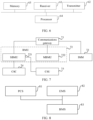
- FIG. 6 is a schematic structural diagram of an embodiment of an EMS according to this application.
- the EMS is disposed in the energy storage system.
- the EMS includes a receiver 61, a transmitter 62, a memory 63, a processor 64, and a computer program stored in the memory 63 and adaptable for running on the processor 64.
- the processor 64 is configured to: execute the computer program to obtain a to-be-upgraded file of the energy storage system; control, by using a PCS in the energy storage system, the energy storage system to disconnect from high voltage when current operating status of the energy storage system allows a program upgrade; and detect status of high voltage connection of the energy storage system by using the BMS.
- That the processor 64 is configured to obtain a to-be-upgraded file of the energy storage system may be: the processor 64 is specifically configured to: receive the to-be-upgraded file of the energy storage system sent by a server, where the to-be-upgraded file of the energy storage system is sent by the server after the to-be-upgraded file uploaded by a client is received, and the to-be-upgraded file uploaded by a client is an encrypted to-be-upgraded file that is uploaded by the client to the server after the client performs format adjustment and/or data encryption on the to-be-upgraded file of the energy storage system; or, the processor 64 is specifically configured to: query the server about a version of the to-be-upgraded file in the server at a preset time or periodically, and obtain an updated to-be-upgraded file from the server if it is detected that the version of the to-be-upgraded file in the server is an updated version; or obtain the to-be-upgraded file of the energy storage system from
- the client after performing format adjustment and/or data encryption on the to-be-upgraded file of the energy storage system, the client uploads the encrypted file to the server through a network. After detecting the to-be-upgraded file uploaded by the client, the server notifies the EMS that a file needs to be upgraded, and sends the to-be-upgraded file to the EMS.
- the processor 64 may query the server about a version of the to-be-upgraded file in the server at a preset time or periodically, and obtain an updated to-be-upgraded file from the server if it is detected that the version of the to-be-upgraded file in the server is an updated version.
- the processor 64 may also obtain the to-be-upgraded file of the energy storage system from the memory connected to the EMS.
- the to-be-upgraded file of the energy storage system may be stored in the memory, and then the memory is connected to the EMS. In this way, the processor 64 can obtain the to-be-upgraded file of the energy storage system from the connected memory.
- the memory may be a device capable of storage, such as a USB flash disk or a mobile hard disk. This embodiment does not limit the form of the memory.
- the receiver 61 is configured to receive a notification sent by the BMS about completion of disconnecting the energy storage system from high voltage.
- the transmitter 62 is configured to send the to-be-upgraded file to the BMS so that the BMS performs the program upgrade according to the to-be-upgraded file.
- the BMS detects the status of high voltage disconnection of the energy storage system and, if it is detected that the energy storage system is disconnected from high voltage, sends a notification to the EMS about completion of disconnecting the energy storage system from high voltage.
- the transmitter 62 may send the to-be-upgraded file to the BMS according to an established communications protocol, so that the BMS performs the program upgrade according to the to-be-upgraded file.
- the processor 64 is further configured to: detect a type of a to-be-upgraded node in the to-be-upgraded file; and obtain, from the to-be-upgraded file, upgrade data corresponding to the type of the to-be-upgraded node.
- the transmitter 62 is specifically configured to send the upgrade data corresponding to the type of the to-be-upgraded node to a communications gateway in the BMS, so that the communications gateway sends the upgrade data corresponding to the type of the to-be-upgraded node to a corresponding to-be-upgraded node to complete the program upgrade for the corresponding to-be-upgraded node.
- the processor 64 may parse the to-be-upgraded file, detect the type of the to-be-upgraded node in the to-be-upgraded file, split the to-be-upgraded file, and obtain, from the to-be-upgraded file, the upgrade data corresponding to the type of the to-be-upgraded node. Finally, the transmitter 62 sends the obtained upgrade data to the communications gateway in the BMS, so that the communications gateway sends the upgrade data to the corresponding to-be-upgraded node to complete the program upgrade for the corresponding to-be-upgraded node.
- the processor 64 controls, by using the PCS, the energy storage system to disconnect from high voltage, and detects the status of high voltage connection of the energy storage system by using the BMS.
- the transmitter 64 sends the to-be-upgraded file to the BMS, so that the BMS performs the program upgrade according to the to-be-upgraded file.
- the program upgrade can be performed for the energy storage system remotely, the upgrade operation of the energy storage system is simplified, and costs of human resources and time are saved.
- the same line can be shared by upgrade and communication, thereby further saving hardware costs.
- FIG. 7 is a schematic structural diagram of an embodiment of a BMS according to this application.
- the BMS provided in this embodiment is disposed in an energy storage system.
- the BMS includes a communications gateway 71.
- the communications gateway 71 is configured to: receive a to-be-upgraded file sent by the EMS, where the to-be-upgraded file is obtained by the EMS; control, by the EMS by using the PCS, the energy storage system to disconnect from high voltage when current operating status of the energy storage system allows a program upgrade, and detect status of high voltage connection of the energy storage system by using the BMS; send the to-be-upgraded file to the BMS after receiving a notification sent by the BMS about completion of disconnecting the energy storage system from high voltage; detect a type of a to-be-upgraded node in the to-be-upgraded file; and perform the program upgrade on the to-be-upgraded node according to the type of the to-be-upgraded node by using the to-be-upgraded file.
- the communications gateway 71 may perform one or more of the following operations on the received to-be-upgraded file: decryption, decompression, verification, and storage.
- the verification may include an integrity check. Nevertheless, this embodiment is not limited to the integrity check.
- the verification may also include other types of checks, such as a legality check. This embodiment does not limit the type of the verification.
- the communications gateway 71 may detect the type of the to-be-upgraded node in the to-be-upgraded file.
- the type of the to-be-upgraded node is indicated in the to-be-upgraded file.
- the upgrade mode varies with the type of the to-be-upgraded node.
- the communications gateway 71 is specifically configured to: set an update flag bit in a non-volatile memory of the communications gateway when the type of the to-be-upgraded node is the communications gateway; after an upgrade request included in the to-be-upgraded file to upgrade the communications gateway is detected, copy upgrade data in the to-be-upgraded file to a designated area of the communications gateway, such as an application (application, (hereinafter referred to as "APP") running area in the communications gateway; verify the upgrade data in the designated area after completion of copying the upgrade data; and run the upgrade data in the designated area of the communications gateway after the upgrade data in the designated area passes the verification, so as to complete the program upgrade of the communications gateway.
- APP application
- the communications gateway 71 may set an update flag bit in an NVM, and then start a program upgrade process (that is, jump to run a boot program).
- the boot program detects that an upgrade request exists currently, and therefore, copies the upgrade data, which is stored in a backup area of the communications gateway, to a designated area (such as an APP running area) of the communications gateway in an established file format.
- the boot program verifies the data in the designated area after completion of copying the upgrade data. After the upgrade data passes the verification, the resetting application is verified valid, and the upgrade data is run in the designated area of the communications gateway 71, so as to complete the program upgrade for the communications gateway.
- the BMS further includes a battery management unit 72 and/or an IMM 73.
- the battery management unit in the BMS may include an SBMU 721 and an MBMU 722.
- the communications gateway 71 is further configured to: send a program upgrade notification to the battery management unit 72 and/or the IMM 73; and obtain upgrade data from the to-be-upgraded file after a program upgrade process of the battery management unit 72 and/or the IMM 73 is started, and send the upgrade data to the battery management unit 72 and/or the IMM 73.
- the battery management unit 72 and/or IMM 73 is configured to: verify the upgrade data and store the upgrade data into a designated area in the battery management unit 72 and/or the IMM 73 after the upgrade data passes the verification, so as to complete the program upgrade for the battery management unit 72 and/or the IMM 73.
- the communications gateway 71 detects that the type of the to-be-upgraded node is SBMU 721, MBMU 722, or IMM 73, firstly the communications gateway 71 instructs the SBMU 721, MBMU 722, or IMM 73 to upgrade the program, and the SBMU 721, MBMU 722, or IMM 73 jumps to run a boot program to start a program upgrade process. Secondly, the communications gateway 71 may directly send the upgrade data, which is obtained from the to-be-upgraded file, to the SBMU 721, MBMU 722, or IMM 73 according to an established upgrade policy and in an established communications format.
- the boot program of the SBMU 721, MBMU 722, or IMM 73 verifies the received upgrade data and, after the upgrade data passes the verification, stores the upgrade data into a designated area to complete the program upgrade for the SBMU 721, MBMU 722, or IMM 73.
- the BMS may further include a CSC 74 and/or a CSU 75.
- the communications gateway 71 is further configured to: send a program upgrade notification to the CSC 74 and/or the CSU 75; and obtain upgrade data from the to-be-upgraded file after a program upgrade process of the CSC 74 and/or the CSU 75 is started, and send the upgrade data to the CSC 74 and/or the CSU 75 through the battery management unit 72.
- the CSC 74 and/or the CSU 75 is configured to: verify the upgrade data and store the upgrade data into a designated area in the CSC 74 and/or the CSU 75 after the upgrade data passes the verification, so as to complete the program upgrade for the CSC 74 and/or the CSU 75.
- the communications gateway 71 detects that the type of the to-be-upgraded node is CSC 74 or CSU 75, firstly the communications gateway 71 instructs the CSC 74 or CSU 75 to upgrade the program, and the CSC 74 or CSU 75 jumps to run a boot program to start a program upgrade process. Secondly, the communications gateway 71 sends the upgrade data, which is obtained from the to-be-upgraded file, to the SBMU 721 according to an established upgrade policy and in an established communications format. The SBMU 721 forwards the upgrade data to the CSC 74 or CSU 75.
- the boot program of the CSC 74 or CSU 75 verifies the received upgrade data and, after the upgrade data passes the verification, stores the upgrade data into a designated area in the CSC 74 or CSU 75 to complete the program upgrade for the CSC 74 or CSU 75.
- the communications gateway 71 is further configured to correct the error according to an error type of the error, and restart to perform a new process of program upgrade if the error fails to be corrected and, when a cumulative quantity of restarts of the same upgrade data exceeds a preset threshold, stop the program upgrade process and report a program upgrade failure notification to the EMS.
- the communications gateway 71 may correct the error by means of packet retransmission.
- the preset threshold of the quantity of restarts may be set according to system performance and/or implementation requirements and the like in a specific implementation. This embodiment does not limit the threshold.
- the threshold may be 5.
- the type of the to-be-upgraded node may include a battery management unit 72, an IMM 73, and/or a CSU 75 in the BMS.
- the to-be-upgraded file includes a preset threshold and/or a preset parameter of the BMS.
- the communications gateway 71 is specifically configured to parse the to-be-upgraded file to obtain the threshold and/or parameter of the BMS included in the to-be-upgraded file; and send the threshold and/or parameter of the BMS to a corresponding to-be-upgraded node in the BMS when it is detected that the current operating status of the BMS allows upgrading.
- the communications gateway 71 in this embodiment may be the communications gateway provided in the embodiment shown in FIG. 9 according to this application.
- FIG. 8 is a schematic structural diagram of an embodiment of an energy storage system according to this application.
- the energy storage system may include a PCS 81, an EMS 82, and a BMS 83.
- the EMS 82 is connected to the PCS 81
- the PCS 81 is connected to the BMS 83
- the EMS 82 is connected to the BMS 83.
- the EMS 82 may be the EMS provided in the embodiment shown in FIG. 6 according to this application
- the BMS 83 may be the BMS provided in the embodiment shown in FIG. 7 according to this application.
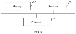
- FIG. 9 is a schematic structural diagram of an embodiment of a communications gateway according to this application.
- the communications gateway is disposed in the BMS.
- the communications gateway may include a receiver 91, a memory 92, a processor 93, and a computer program stored in the memory 92 and adaptable for running on the processor 93.
- the processor 93 can implement the method provided in the embodiment shown in FIG. 5 for upgrading an energy storage system remotely according to this application.
- An embodiment of this application further provides a remote upgrade system for an energy storage system, including: a client, a server, and the energy storage system provided in the embodiment shown in FIG. 8 .
- the remote upgrade system for an energy storage system may adopt the architecture shown in FIG. 1 , and details are omitted here.
- An embodiment of this application further provides a non-transitory computer-readable storage medium on which a computer program is stored.
- the computer program When executed by a processor, the computer program implements the method provided in the embodiment shown in FIG. 4 or FIG. 5 for upgrading an energy storage system remotely according to this application.
- the non-transitory computer-readable storage medium may be any combination of one or more computer-readable medium(s).
- the computer-readable medium may be a computer-readable signal medium or a computer-readable storage medium.
- a computer-readable storage medium may be, for example, but not limited to, an electronic, magnetic, optical, electromagnetic, infrared, or semiconductor system, apparatus, or device, or any suitable combination thereof.
- the computer-readable storage medium includes: an electrical connection having one or more wires, a portable computer diskette, a hard disk, a random access memory (RAM), a read-only memory (read-only memory, hereinafter referred to as "ROM”), an erasable programmable read-only memory (erasable programmable read-only memory, hereinafter referred to as "EPROM”) or flash memory, an optical fiber, a portable compact disc read-only memory (CD-ROM), an optical storage device, a magnetic storage device, or any suitable combination thereof.
- a computer-readable storage medium may be any tangible medium that can contain or store a program for use by or in connection with an instruction execution system, apparatus, or device.
- a computer-readable signal medium may include a propagated data signal with computer-readable program code embodied therein, for example, in baseband or as part of a carrier wave. Such a propagated signal may take any of a variety of forms, including, but not limited to, electromagnetic, optical, or any suitable combination thereof.
- a computer-readable signal medium may be any computer-readable medium that is not a computer-readable storage medium and that can communicate, propagate, or transport a program for use by or in connection with an instruction execution system, apparatus, or device.
- Program code embodied on a computer-readable medium may be transmitted using any appropriate medium, including but not limited to wireless, wireline, optical fiber cable, radio frequency (radio frequency, hereinafter referred to as "RF"), or any suitable combination thereof.
- RF radio frequency
- Computer program code for carrying out operations under this application may be written in any combination of one or more programming languages, including an object oriented programming language such as Java, Smalltalk, C++ or the like and conventional procedural programming languages, such as the "C" programming language or similar programming languages.
- the program code may be executed entirely on the user's computer, partly on the user's computer, as a stand-alone software package, partly on the user's computer and partly on a remote computer, or entirely on a remote computer or server.
- the remote computer may be connected to the user's computer through any type of network, including a local area network (local area network, hereinafter referred to as "LAN”) or a wide area network (wide area network, hereinafter referred to as "WAN”), or may be connected to an external computer (for example, through the Internet using an Internet Service Provider).
- LAN local area network
- WAN wide area network
- first and second are used for descriptive purposes only and are not to be construed as indicating or implying a relative importance or implicitly indicating the number of technical features indicated. Therefore, the features preceded by “first” or “second” may explicitly or implicitly include at least one of the features.
- a plurality of means at least two, for example, two, three, or more.
- Any process or method illustrated in a flowchart or otherwise described herein may be understood as representing a module, segment, or portion of code that includes one or more executable instructions for implementing the steps of the specified logical function(s) or process(es).
- the scope of an exemplary implementation of this application shall include alternative implementations.
- the steps may occur out of the order illustrated or discussed herein.
- the functions described or illustrated in succession may, in fact, be executed substantially concurrently, or the functions may sometimes be executed in the reverse order, depending upon the functionality involved, which is understandable to those skilled in the technical field to which the embodiments of this application relate.
- the word “if” as used herein may be interpreted as “at the time of” or “when” or “in response to determination” or “in response to detection.”
- the phrase “if determined” or “if detected (conditions or events stated)” may be interpreted as “when determined” or “in response to determination” or “when detected (conditions or events stated)” or “in response to detection (conditions or events stated).”
- the terminals referred to in the embodiments of this application may include, but without limitation, a personal computer (personal computer, hereinafter referred to as "PC”), a personal digital assistant (personal digital assistant, hereinafter referred to as "PDA”), a wireless handheld device, a tablet computer (tablet computer), a mobile phone, an MP3 player, and an MP4 player.
- PC personal computer
- PDA personal digital assistant
- the disclosed system, apparatus, and method may be implemented in other manners.
- the apparatus embodiment described above is merely exemplary.
- the unit division is merely division with respect to logical functions, and in actual implementations, the units may be divided in other manners.
- a plurality of units or components may be combined or integrated into another system, or some features may be ignored or not implemented.
- the displayed or discussed mutual couplings or direct couplings or communication connections may be implemented through some interfaces.
- the indirect couplings or communication connections between the apparatuses or units may be implemented in electronic, mechanical or other forms.
- function units in the embodiments of this application may be integrated into one processing unit, or each of the units may exist alone physically, or two or more units may be integrated into one unit.
- the integrated unit may be implemented in the form of hardware, or in the form of both hardware and a software function unit.
- the integrated unit implemented in the form of a software function unit may be stored in a computer-readable storage medium.
- the software function unit is stored in a storage medium including a plurality of instructions that cause a computer device (such as a personal computer, a server, or a network device) or a processor (processor) to implement a part of steps of the method described in each embodiment of this application.
- the storage medium includes any medium that can store program code, for example, a USB flash disk, a removable hard disk, a read-only memory (read-only memory, hereinafter referred to as "ROM”), a random access memory (random access memory, hereinafter referred to as "RAM”), a magnetic disk, or an optical disk.
Landscapes
- Engineering & Computer Science (AREA)
- Theoretical Computer Science (AREA)
- General Engineering & Computer Science (AREA)
- Software Systems (AREA)
- Physics & Mathematics (AREA)
- General Physics & Mathematics (AREA)
- Signal Processing (AREA)
- Computer Networks & Wireless Communication (AREA)
- Computer Security & Cryptography (AREA)
- Power Engineering (AREA)
- Quality & Reliability (AREA)
- Health & Medical Sciences (AREA)
- Computing Systems (AREA)
- General Health & Medical Sciences (AREA)
- Medical Informatics (AREA)
- Stored Programmes (AREA)
Claims (5)
- Procédé de mise à niveau à distance d'un système de stockage d'énergie, appliqué à un système de stockage d'énergie, dans lequel le système de stockage d'énergie comprend un système de gestion d'énergie (82), un système de gestion de batterie (83) et un système de conversion de puissance, et le procédé de mise à niveau à distance d'un système de stockage d'énergie comprend :la réception, par une passerelle de communication (71) dans le système de gestion de batterie (83), d'un fichier à mettre à niveau envoyé par le système de gestion d'énergie (82), dans lequel le fichier à mettre à niveau est obtenu par le système de gestion d'énergie (82) ; la commande, par le système de gestion d'énergie (82) à l'aide du système de conversion de puissance, du système de stockage d'énergie pour le déconnecter de la haute tension lorsque l'état de fonctionnement actuel du système de stockage d'énergie permet une mise à niveau de programme, et la détection de l'état de connexion à la haute tension du système de stockage d'énergie à l'aide du système de gestion de batterie (83) ; et l'envoi du fichier à mettre à niveau au système de gestion de batterie (83) après réception d'une notification envoyée par le système de gestion de batterie (83) concernant l'achèvement de la déconnexion du système de stockage d'énergie de la haute tension,la détection d'un type de noeud à mettre à niveau dans le fichier à mettre à niveau ; etla réalisation de la mise à niveau de programme sur le noeud à mettre à niveau conformément au type de noeud à mettre à niveau à l'aide du fichier à mettre à niveau ; dans lequel le type de noeud à mettre à niveau comprend la passerelle de communication (71) ; etla réalisation de la mise à niveau de programme sur le noeud à mettre à niveau conformément au type de noeud à mettre à niveau à l'aide du fichier à mettre à niveau comprend :l'activation d'un bit indicateur de mise à jour dans une mémoire non volatile de la passerelle de communication (71) ;la copie de données de mise à niveau dans le fichier à mettre à niveau dans une zone désignée de la passerelle de communication (71) après la détection d'une demande de mise à niveau comprise dans le fichier à mettre à niveau pour mettre à niveau la passerelle de communication (71);la vérification des données de mise à niveau dans la zone désignée après l'achèvement de la copie des données de mise à niveau ; etl'exécution des données de mise à niveau dans la zone désignée de la passerelle de communication (71) après la vérification positive des données de mise à niveau dans la zone désignée, de manière à achever la mise à niveau de programme pour la passerelle de communication (71).
- Passerelle de communication (71), configurée pour être disposée dans un système de gestion de batterie (83), la passerelle de communication (71) comprenant un récepteur, une mémoire, un processeur et un programme informatique stocké dans la mémoire et adaptable pour être exécuté sur le processeur ; et dans laquelle le processeur met en oeuvre le procédé selon l'une quelconque des revendications précédentes lors de l'exécution du programme d'ordinateur.
- Système de gestion de batterie (83), configuré pour être disposé dans un système de stockage d'énergie, le système de gestion de batterie (83) comprenant la passerelle de communication (71) selon la revendication précédente.
- Système de stockage d'énergie, comprenant : un système de conversion de puissance, un système de gestion d'énergie (82) et le système de gestion de batterie (83) selon la revendication précédente, le système de gestion d'énergie (82) étant connecté au système de conversion de puissance, le système de conversion de puissance étant connecté au système de gestion de batterie (83) et le système de gestion d'énergie (82) étant connecté au système de gestion de batterie (83).
- Système de mise à niveau à distance pour un système de stockage d'énergie, comprenant : un client, un serveur et le système de stockage d'énergie selon la revendication précédente.
Applications Claiming Priority (2)
| Application Number | Priority Date | Filing Date | Title |
|---|---|---|---|
| CN201910181503.6A CN111694579B (zh) | 2019-03-11 | 2019-03-11 | 储能系统的远程升级方法、能量管理系统和电池管理系统 |
| PCT/CN2020/077702 WO2020182023A1 (fr) | 2019-03-11 | 2020-03-04 | Procédé de mise à niveau à distance pour système de stockage d'énergie, système de gestion d'énergie et système de gestion de batterie |
Publications (4)
| Publication Number | Publication Date |
|---|---|
| EP3799397A1 EP3799397A1 (fr) | 2021-03-31 |
| EP3799397A4 EP3799397A4 (fr) | 2021-09-29 |
| EP3799397B1 true EP3799397B1 (fr) | 2024-08-21 |
| EP3799397B8 EP3799397B8 (fr) | 2024-10-09 |
Family
ID=72426905
Family Applications (1)
| Application Number | Title | Priority Date | Filing Date |
|---|---|---|---|
| EP20769922.4A Active EP3799397B8 (fr) | 2019-03-11 | 2020-03-04 | Procédé de mise à jour du système de stockage d'énergie à distance, système de gestion de l'énergie, et système de gestion de batterie |
Country Status (6)
| Country | Link |
|---|---|
| US (1) | US11550561B2 (fr) |
| EP (1) | EP3799397B8 (fr) |
| CN (1) | CN111694579B (fr) |
| HU (1) | HUE068972T2 (fr) |
| PL (1) | PL3799397T3 (fr) |
| WO (1) | WO2020182023A1 (fr) |
Families Citing this family (25)
| Publication number | Priority date | Publication date | Assignee | Title |
|---|---|---|---|---|
| CN112383439B (zh) * | 2020-11-24 | 2023-07-25 | 重庆前卫表业有限公司 | 一种智能燃气表空中升级系统及升级方法 |
| CN112732311B (zh) * | 2020-12-28 | 2024-05-03 | 上海瑞浦青创新能源有限公司 | 一种大型储能系统bms程序热更新方法、系统及介质 |
| CN113238788B (zh) * | 2021-05-14 | 2024-03-29 | 山东云海国创云计算装备产业创新中心有限公司 | 一种bios升级方法及相关装置 |
| CN113282319A (zh) * | 2021-05-28 | 2021-08-20 | 武汉天喻信息产业股份有限公司 | 一种智能卡及其更新方法 |
| CN113452761B (zh) * | 2021-06-07 | 2023-08-15 | 阳光电源股份有限公司 | 储能系统的更新方法、更新管理设备、储能系统及介质 |
| CN113342374B (zh) * | 2021-06-15 | 2022-12-13 | 东莞新能安科技有限公司 | 电池管理系统升级方法及电子装置 |
| CN113320491A (zh) * | 2021-07-16 | 2021-08-31 | 重庆金康赛力斯新能源汽车设计院有限公司 | 一种控制器升级方法和系统 |
| CN113672256A (zh) * | 2021-08-03 | 2021-11-19 | 东莞新能安科技有限公司 | 可执行文件的处理方法及服务端、软件升级方法及客户端 |
| CN113656055A (zh) * | 2021-08-20 | 2021-11-16 | 深圳壹账通智能科技有限公司 | 系统架构升级方法、装置、计算机设备和存储介质 |
| CN114089660B (zh) * | 2021-11-09 | 2024-12-17 | 浙江浙能技术研究院有限公司 | 一种电池管理系统批量升级与参数修改系统 |
| CN114201194B (zh) * | 2021-11-24 | 2024-12-03 | 东莞新能安科技有限公司 | 一种并机系统升级方法、装置以及并机系统 |
| CN114448795B (zh) * | 2022-01-18 | 2025-02-07 | 深圳市联洲国际技术有限公司 | 无线模组升级的方法、路由板、无线通信系统和处理器 |
| CN115061703A (zh) * | 2022-05-23 | 2022-09-16 | 八方新能源(苏州)有限公司 | 一种电动助力车的无线升级bms程序的方法 |
| CN114816460A (zh) * | 2022-06-29 | 2022-07-29 | 上海捷勃特机器人有限公司 | 一种机器人系统远程升级微控制器的装置及其方法 |
| CN115904456A (zh) * | 2023-01-09 | 2023-04-04 | 宁波德业储能科技有限公司 | 一种储能系统固件升级的方法 |
| CN116048581A (zh) * | 2023-02-07 | 2023-05-02 | 江苏天合储能有限公司 | 应用更新方法及装置、电子设备、计算机可读存储介质 |
| CN116009925B (zh) * | 2023-03-24 | 2023-07-14 | 合肥力高动力科技有限公司 | 一种电池管理系统的子电池管理单元程序刷写方法 |
| CN118826195A (zh) * | 2023-04-20 | 2024-10-22 | 中兴通讯股份有限公司 | 电源管理方法、电池管理方法及设备、网管系统、介质 |
| TWI870060B (zh) * | 2023-04-28 | 2025-01-11 | 仁寶電腦工業股份有限公司 | 電子裝置以及其電源管理方法 |
| CN117134505A (zh) * | 2023-10-26 | 2023-11-28 | 潍坊学院 | 一种储能电站运行监测管理系统 |
| CN117519746B (zh) * | 2023-10-26 | 2024-08-16 | 郑州优碧科技有限公司 | 电力线路信号采集前端的升级方法、系统、设备及介质 |
| CN117519759B (zh) * | 2023-12-29 | 2024-04-02 | 广云物联网科技(广州)有限公司 | 家庭储能系统设备远程升级方法及系统 |
| CN117785247A (zh) * | 2024-02-26 | 2024-03-29 | 双一力(宁波)电池有限公司 | 一种储能系统的设备升级方法、装置及系统 |
| CN118092980B (zh) * | 2024-04-18 | 2024-06-28 | 福建时代星云科技有限公司 | 一种pcs远程升级方法及终端 |
| CN118708211A (zh) * | 2024-08-28 | 2024-09-27 | 云储新能源科技有限公司 | 一种新能源电力储能主从机系统的升级方法、设备及介质 |
Citations (1)
| Publication number | Priority date | Publication date | Assignee | Title |
|---|---|---|---|---|
| CN108874430A (zh) * | 2018-08-15 | 2018-11-23 | 北京车和家信息技术有限公司 | 电子控制单元ecu升级方法、装置及电池管理系统 |
Family Cites Families (14)
| Publication number | Priority date | Publication date | Assignee | Title |
|---|---|---|---|---|
| US6230194B1 (en) * | 1997-07-14 | 2001-05-08 | Freegate Corporation | Upgrading a secure network interface |
| US9128798B2 (en) * | 2012-10-17 | 2015-09-08 | Movimento Group | Module updating device |
| CN103337869B (zh) * | 2013-07-17 | 2016-04-20 | 国家电网公司 | 一种新型电池储能系统及其功能一体化设计的方法 |
| CN104590027B (zh) * | 2013-10-31 | 2017-02-15 | 北汽福田汽车股份有限公司 | 汽车的高压下电控制方法、系统及具有其的汽车 |
| CN105491161A (zh) * | 2016-01-19 | 2016-04-13 | 深圳市沃特玛电池有限公司 | 一种电池管理系统软件的远程升级系统及其远程升级方法 |
| CN105930236A (zh) * | 2016-07-15 | 2016-09-07 | 深圳市沃特玛电池有限公司 | 一种基于BMS Bootloader升级的应用程序版本回退方法 |
| CN106254496B (zh) * | 2016-08-19 | 2023-04-18 | 江苏天合储能有限公司 | 户用光伏储能设备的远程升级系统及其方法 |
| CN106302761A (zh) * | 2016-08-19 | 2017-01-04 | 江苏天合储能有限公司 | 户用光伏储能设备的远程数据交互系统及其方法 |
| CN106873417A (zh) * | 2017-03-28 | 2017-06-20 | 深圳市沃特玛电池有限公司 | 储能系统及远程升级方法 |
| CN107222517B (zh) * | 2017-04-12 | 2020-02-14 | 惠州市蓝微新源技术有限公司 | 一种电池管理系统软件的远程升级系统及远程升级方法 |
| CN107097667A (zh) * | 2017-04-28 | 2017-08-29 | 北京新能源汽车股份有限公司 | 一种电动汽车的充电方法及装置 |
| CN107831442A (zh) | 2017-10-18 | 2018-03-23 | 苏州协鑫集成储能科技有限公司 | 远程估算soc的方法、装置、存储介质及计算机设备 |
| CN109408084B (zh) * | 2018-09-26 | 2024-06-18 | 深圳市科陆电子科技股份有限公司 | 一种通过互联网远程升级储能bms设备的方法和系统 |
| CN109066926A (zh) * | 2018-10-12 | 2018-12-21 | 四川长虹电器股份有限公司 | 基于安卓平台对bms实现监控和升级的系统 |
-
2019
- 2019-03-11 CN CN201910181503.6A patent/CN111694579B/zh active Active
-
2020
- 2020-03-04 HU HUE20769922A patent/HUE068972T2/hu unknown
- 2020-03-04 WO PCT/CN2020/077702 patent/WO2020182023A1/fr not_active Ceased
- 2020-03-04 EP EP20769922.4A patent/EP3799397B8/fr active Active
- 2020-03-04 PL PL20769922.4T patent/PL3799397T3/pl unknown
- 2020-12-29 US US17/137,056 patent/US11550561B2/en active Active
Patent Citations (1)
| Publication number | Priority date | Publication date | Assignee | Title |
|---|---|---|---|---|
| CN108874430A (zh) * | 2018-08-15 | 2018-11-23 | 北京车和家信息技术有限公司 | 电子控制单元ecu升级方法、装置及电池管理系统 |
Also Published As
| Publication number | Publication date |
|---|---|
| CN111694579B (zh) | 2021-10-29 |
| US11550561B2 (en) | 2023-01-10 |
| WO2020182023A1 (fr) | 2020-09-17 |
| US20210117180A1 (en) | 2021-04-22 |
| PL3799397T3 (pl) | 2025-02-10 |
| EP3799397A4 (fr) | 2021-09-29 |
| EP3799397B8 (fr) | 2024-10-09 |
| EP3799397A1 (fr) | 2021-03-31 |
| CN111694579A (zh) | 2020-09-22 |
| HUE068972T2 (hu) | 2025-02-28 |
Similar Documents
| Publication | Publication Date | Title |
|---|---|---|
| EP3799397B1 (fr) | Procédé de mise à jour du système de stockage d'énergie à distance, système de gestion de l'énergie, et système de gestion de batterie | |
| CN110621011B (zh) | 一种基于蓝牙设备端的ota固件升级方法及系统 | |
| CN101610501A (zh) | 设备固件升级系统及方法、设备管理服务器及移动终端 | |
| US11228514B2 (en) | Network diagnosis method, cloud intelligent robot, network device and private network | |
| US20210255845A1 (en) | On-board update apparatus, program, and method for updating program or data | |
| CN107483262A (zh) | 故障处理方法及设备 | |
| CN113918202B (zh) | 一种支持iap功能的单片机远程升级固件的方法与设备 | |
| EP3780700B1 (fr) | Procédé de notification d'anomalie de consommation d'énergie, serveur, et terminal | |
| CN112423321B (zh) | 一种基于无线广播的升级方法和装置及电子设备 | |
| CN106033191A (zh) | 家电设备的控制方法及装置 | |
| WO2022257927A1 (fr) | Procédé et appareil de gravure de clé, carte de dispositif électronique et support de stockage | |
| US10430174B2 (en) | Terminal device and charge control method | |
| CN110045969B (zh) | 应用程序安装方法、服务器、系统、设备及存储介质 | |
| JP7219568B2 (ja) | 基地局、制御方法およびプログラム | |
| EP3026949A1 (fr) | Procédé de traitement d'informations, dispositif associé et système de communication | |
| EP3082376A1 (fr) | Procédé de découverte de dispositif de réseau, dispositif de réseau et système de découverte de dispositif de réseau | |
| CN111522571A (zh) | 设备升级方法、装置、终端设备及存储介质 | |
| US11223979B2 (en) | Method for handling data radio bearer integrity check failure and network equipment | |
| CN112788648A (zh) | 一种控制方法、终端及存储介质 | |
| CN117320182A (zh) | 连接的优化方法、装置、设备及存储介质 | |
| JP2024139013A (ja) | Sim、通信装置、切替方法、及びプログラム | |
| WO2017219675A1 (fr) | Procédé, dispositif et système de protection contre les surcharges | |
| US20080010554A1 (en) | System for prechecking corrective actions on parameterable elements causing problems in a communicating network | |
| CN115098137A (zh) | 电池保护板的升级方法、装置、检测仪、系统及存储介质 | |
| CN117423918B (zh) | 一种电源智能化管理方法及管理系统 |
Legal Events
| Date | Code | Title | Description |
|---|---|---|---|
| STAA | Information on the status of an ep patent application or granted ep patent |
Free format text: STATUS: THE INTERNATIONAL PUBLICATION HAS BEEN MADE |
|
| PUAI | Public reference made under article 153(3) epc to a published international application that has entered the european phase |
Free format text: ORIGINAL CODE: 0009012 |
|
| STAA | Information on the status of an ep patent application or granted ep patent |
Free format text: STATUS: REQUEST FOR EXAMINATION WAS MADE |
|
| 17P | Request for examination filed |
Effective date: 20201223 |
|
| AK | Designated contracting states |
Kind code of ref document: A1 Designated state(s): AL AT BE BG CH CY CZ DE DK EE ES FI FR GB GR HR HU IE IS IT LI LT LU LV MC MK MT NL NO PL PT RO RS SE SI SK SM TR |
|
| AX | Request for extension of the european patent |
Extension state: BA ME |
|
| A4 | Supplementary search report drawn up and despatched |
Effective date: 20210831 |
|
| RIC1 | Information provided on ipc code assigned before grant |
Ipc: G06F 8/65 20180101ALI20210825BHEP Ipc: H04L 29/08 20060101AFI20210825BHEP |
|
| DAV | Request for validation of the european patent (deleted) | ||
| DAX | Request for extension of the european patent (deleted) | ||
| STAA | Information on the status of an ep patent application or granted ep patent |
Free format text: STATUS: EXAMINATION IS IN PROGRESS |
|
| 17Q | First examination report despatched |
Effective date: 20221018 |
|
| REG | Reference to a national code |
Ref country code: DE Ref legal event code: R079 Free format text: PREVIOUS MAIN CLASS: H04L0029080000 Ipc: H04L0067025000 Ref country code: DE Ref legal event code: R079 Ref document number: 602020036275 Country of ref document: DE Free format text: PREVIOUS MAIN CLASS: H04L0029080000 Ipc: H04L0067025000 |
|
| GRAP | Despatch of communication of intention to grant a patent |
Free format text: ORIGINAL CODE: EPIDOSNIGR1 |
|
| STAA | Information on the status of an ep patent application or granted ep patent |
Free format text: STATUS: GRANT OF PATENT IS INTENDED |
|
| RIC1 | Information provided on ipc code assigned before grant |
Ipc: G06F 8/65 20180101ALI20240319BHEP Ipc: H04L 67/562 20220101ALI20240319BHEP Ipc: H04L 67/55 20220101ALI20240319BHEP Ipc: H04L 67/00 20220101ALI20240319BHEP Ipc: H04L 67/025 20220101AFI20240319BHEP |
|
| INTG | Intention to grant announced |
Effective date: 20240419 |
|
| GRAS | Grant fee paid |
Free format text: ORIGINAL CODE: EPIDOSNIGR3 |
|
| GRAA | (expected) grant |
Free format text: ORIGINAL CODE: 0009210 |
|
| STAA | Information on the status of an ep patent application or granted ep patent |
Free format text: STATUS: THE PATENT HAS BEEN GRANTED |
|
| AK | Designated contracting states |
Kind code of ref document: B1 Designated state(s): AL AT BE BG CH CY CZ DE DK EE ES FI FR GB GR HR HU IE IS IT LI LT LU LV MC MK MT NL NO PL PT RO RS SE SI SK SM TR |
|
| RAP3 | Party data changed (applicant data changed or rights of an application transferred) |
Owner name: CONTEMPORARY AMPEREX TECHNOLOGY CO., LIMITED |
|
| REG | Reference to a national code |
Ref country code: GB Ref legal event code: FG4D |
|
| REG | Reference to a national code |
Ref country code: CH Ref legal event code: EP |
|
| REG | Reference to a national code |
Ref country code: IE Ref legal event code: FG4D |
|
| REG | Reference to a national code |
Ref country code: DE Ref legal event code: R081 Ref document number: 602020036275 Country of ref document: DE Owner name: CONTEMPORARY AMPEREX TECHNOLOGY (HONG KONG) LI, HK Free format text: FORMER OWNER: CONTEMPORARY AMPEREX TECHNOLOGY CO., LIMITED, NINGDE CITY, FUJIAN, CN Ref country code: DE Ref legal event code: R096 Ref document number: 602020036275 Country of ref document: DE |
|
| REG | Reference to a national code |
Ref country code: CH Ref legal event code: PK Free format text: BERICHTIGUNG B8 |
|
| RAP2 | Party data changed (patent owner data changed or rights of a patent transferred) |
Owner name: CONTEMPORARY AMPEREX TECHNOLOGY(HONG KONG) LIMITED |
|
| P01 | Opt-out of the competence of the unified patent court (upc) registered |
Free format text: CASE NUMBER: APP_53012/2024 Effective date: 20240923 |
|
| REG | Reference to a national code |
Ref country code: NL Ref legal event code: FP |
|
| REG | Reference to a national code |
Ref country code: LT Ref legal event code: MG9D |
|
| REG | Reference to a national code |
Ref country code: AT Ref legal event code: MK05 Ref document number: 1716676 Country of ref document: AT Kind code of ref document: T Effective date: 20240821 |
|
| PG25 | Lapsed in a contracting state [announced via postgrant information from national office to epo] |
Ref country code: FI Free format text: LAPSE BECAUSE OF FAILURE TO SUBMIT A TRANSLATION OF THE DESCRIPTION OR TO PAY THE FEE WITHIN THE PRESCRIBED TIME-LIMIT Effective date: 20240821 Ref country code: GR Free format text: LAPSE BECAUSE OF FAILURE TO SUBMIT A TRANSLATION OF THE DESCRIPTION OR TO PAY THE FEE WITHIN THE PRESCRIBED TIME-LIMIT Effective date: 20241122 Ref country code: PT Free format text: LAPSE BECAUSE OF FAILURE TO SUBMIT A TRANSLATION OF THE DESCRIPTION OR TO PAY THE FEE WITHIN THE PRESCRIBED TIME-LIMIT Effective date: 20241223 |
|
| PG25 | Lapsed in a contracting state [announced via postgrant information from national office to epo] |
Ref country code: BG Free format text: LAPSE BECAUSE OF FAILURE TO SUBMIT A TRANSLATION OF THE DESCRIPTION OR TO PAY THE FEE WITHIN THE PRESCRIBED TIME-LIMIT Effective date: 20240821 |
|
| PG25 | Lapsed in a contracting state [announced via postgrant information from national office to epo] |
Ref country code: LV Free format text: LAPSE BECAUSE OF FAILURE TO SUBMIT A TRANSLATION OF THE DESCRIPTION OR TO PAY THE FEE WITHIN THE PRESCRIBED TIME-LIMIT Effective date: 20240821 |
|
| PG25 | Lapsed in a contracting state [announced via postgrant information from national office to epo] |
Ref country code: AT Free format text: LAPSE BECAUSE OF FAILURE TO SUBMIT A TRANSLATION OF THE DESCRIPTION OR TO PAY THE FEE WITHIN THE PRESCRIBED TIME-LIMIT Effective date: 20240821 Ref country code: IS Free format text: LAPSE BECAUSE OF FAILURE TO SUBMIT A TRANSLATION OF THE DESCRIPTION OR TO PAY THE FEE WITHIN THE PRESCRIBED TIME-LIMIT Effective date: 20241221 |
|
| PG25 | Lapsed in a contracting state [announced via postgrant information from national office to epo] |
Ref country code: HR Free format text: LAPSE BECAUSE OF FAILURE TO SUBMIT A TRANSLATION OF THE DESCRIPTION OR TO PAY THE FEE WITHIN THE PRESCRIBED TIME-LIMIT Effective date: 20240821 |
|
| PG25 | Lapsed in a contracting state [announced via postgrant information from national office to epo] |
Ref country code: RS Free format text: LAPSE BECAUSE OF FAILURE TO SUBMIT A TRANSLATION OF THE DESCRIPTION OR TO PAY THE FEE WITHIN THE PRESCRIBED TIME-LIMIT Effective date: 20241121 Ref country code: ES Free format text: LAPSE BECAUSE OF FAILURE TO SUBMIT A TRANSLATION OF THE DESCRIPTION OR TO PAY THE FEE WITHIN THE PRESCRIBED TIME-LIMIT Effective date: 20240821 |
|
| PG25 | Lapsed in a contracting state [announced via postgrant information from national office to epo] |
Ref country code: RS Free format text: LAPSE BECAUSE OF FAILURE TO SUBMIT A TRANSLATION OF THE DESCRIPTION OR TO PAY THE FEE WITHIN THE PRESCRIBED TIME-LIMIT Effective date: 20241121 Ref country code: PT Free format text: LAPSE BECAUSE OF FAILURE TO SUBMIT A TRANSLATION OF THE DESCRIPTION OR TO PAY THE FEE WITHIN THE PRESCRIBED TIME-LIMIT Effective date: 20241223 Ref country code: LV Free format text: LAPSE BECAUSE OF FAILURE TO SUBMIT A TRANSLATION OF THE DESCRIPTION OR TO PAY THE FEE WITHIN THE PRESCRIBED TIME-LIMIT Effective date: 20240821 Ref country code: IS Free format text: LAPSE BECAUSE OF FAILURE TO SUBMIT A TRANSLATION OF THE DESCRIPTION OR TO PAY THE FEE WITHIN THE PRESCRIBED TIME-LIMIT Effective date: 20241221 Ref country code: HR Free format text: LAPSE BECAUSE OF FAILURE TO SUBMIT A TRANSLATION OF THE DESCRIPTION OR TO PAY THE FEE WITHIN THE PRESCRIBED TIME-LIMIT Effective date: 20240821 Ref country code: GR Free format text: LAPSE BECAUSE OF FAILURE TO SUBMIT A TRANSLATION OF THE DESCRIPTION OR TO PAY THE FEE WITHIN THE PRESCRIBED TIME-LIMIT Effective date: 20241122 Ref country code: FI Free format text: LAPSE BECAUSE OF FAILURE TO SUBMIT A TRANSLATION OF THE DESCRIPTION OR TO PAY THE FEE WITHIN THE PRESCRIBED TIME-LIMIT Effective date: 20240821 Ref country code: ES Free format text: LAPSE BECAUSE OF FAILURE TO SUBMIT A TRANSLATION OF THE DESCRIPTION OR TO PAY THE FEE WITHIN THE PRESCRIBED TIME-LIMIT Effective date: 20240821 Ref country code: BG Free format text: LAPSE BECAUSE OF FAILURE TO SUBMIT A TRANSLATION OF THE DESCRIPTION OR TO PAY THE FEE WITHIN THE PRESCRIBED TIME-LIMIT Effective date: 20240821 Ref country code: AT Free format text: LAPSE BECAUSE OF FAILURE TO SUBMIT A TRANSLATION OF THE DESCRIPTION OR TO PAY THE FEE WITHIN THE PRESCRIBED TIME-LIMIT Effective date: 20240821 |
|
| REG | Reference to a national code |
Ref country code: HU Ref legal event code: AG4A Ref document number: E068972 Country of ref document: HU |
|
| PG25 | Lapsed in a contracting state [announced via postgrant information from national office to epo] |
Ref country code: DK Free format text: LAPSE BECAUSE OF FAILURE TO SUBMIT A TRANSLATION OF THE DESCRIPTION OR TO PAY THE FEE WITHIN THE PRESCRIBED TIME-LIMIT Effective date: 20240821 Ref country code: RO Free format text: LAPSE BECAUSE OF FAILURE TO SUBMIT A TRANSLATION OF THE DESCRIPTION OR TO PAY THE FEE WITHIN THE PRESCRIBED TIME-LIMIT Effective date: 20240821 Ref country code: SM Free format text: LAPSE BECAUSE OF FAILURE TO SUBMIT A TRANSLATION OF THE DESCRIPTION OR TO PAY THE FEE WITHIN THE PRESCRIBED TIME-LIMIT Effective date: 20240821 |
|
| PG25 | Lapsed in a contracting state [announced via postgrant information from national office to epo] |
Ref country code: CZ Free format text: LAPSE BECAUSE OF FAILURE TO SUBMIT A TRANSLATION OF THE DESCRIPTION OR TO PAY THE FEE WITHIN THE PRESCRIBED TIME-LIMIT Effective date: 20240821 |
|
| PG25 | Lapsed in a contracting state [announced via postgrant information from national office to epo] |
Ref country code: SK Free format text: LAPSE BECAUSE OF FAILURE TO SUBMIT A TRANSLATION OF THE DESCRIPTION OR TO PAY THE FEE WITHIN THE PRESCRIBED TIME-LIMIT Effective date: 20240821 |
|
| REG | Reference to a national code |
Ref country code: DE Ref legal event code: R097 Ref document number: 602020036275 Country of ref document: DE |
|
| PLBE | No opposition filed within time limit |
Free format text: ORIGINAL CODE: 0009261 |
|
| STAA | Information on the status of an ep patent application or granted ep patent |
Free format text: STATUS: NO OPPOSITION FILED WITHIN TIME LIMIT |
|
| 26N | No opposition filed |
Effective date: 20250522 |
|
| PG25 | Lapsed in a contracting state [announced via postgrant information from national office to epo] |
Ref country code: SE Free format text: LAPSE BECAUSE OF FAILURE TO SUBMIT A TRANSLATION OF THE DESCRIPTION OR TO PAY THE FEE WITHIN THE PRESCRIBED TIME-LIMIT Effective date: 20240821 |
|
| PG25 | Lapsed in a contracting state [announced via postgrant information from national office to epo] |
Ref country code: MC Free format text: LAPSE BECAUSE OF FAILURE TO SUBMIT A TRANSLATION OF THE DESCRIPTION OR TO PAY THE FEE WITHIN THE PRESCRIBED TIME-LIMIT Effective date: 20240821 |
|
| REG | Reference to a national code |
Ref country code: CH Ref legal event code: H13 Free format text: ST27 STATUS EVENT CODE: U-0-0-H10-H13 (AS PROVIDED BY THE NATIONAL OFFICE) Effective date: 20251023 |
|
| PG25 | Lapsed in a contracting state [announced via postgrant information from national office to epo] |
Ref country code: LU Free format text: LAPSE BECAUSE OF NON-PAYMENT OF DUE FEES Effective date: 20250304 |
|
| REG | Reference to a national code |
Ref country code: BE Ref legal event code: MM Effective date: 20250331 |
|
| PG25 | Lapsed in a contracting state [announced via postgrant information from national office to epo] |
Ref country code: BE Free format text: LAPSE BECAUSE OF NON-PAYMENT OF DUE FEES Effective date: 20250331 |
|
| PG25 | Lapsed in a contracting state [announced via postgrant information from national office to epo] |
Ref country code: CH Free format text: LAPSE BECAUSE OF NON-PAYMENT OF DUE FEES Effective date: 20250331 |
|
| PG25 | Lapsed in a contracting state [announced via postgrant information from national office to epo] |
Ref country code: IE Free format text: LAPSE BECAUSE OF NON-PAYMENT OF DUE FEES Effective date: 20250304 |
|
| PGFP | Annual fee paid to national office [announced via postgrant information from national office to epo] |
Ref country code: GB Payment date: 20260325 Year of fee payment: 7 |
|
| PGFP | Annual fee paid to national office [announced via postgrant information from national office to epo] |
Ref country code: NO Payment date: 20260324 Year of fee payment: 7 Ref country code: DE Payment date: 20260324 Year of fee payment: 7 |
|
| PGFP | Annual fee paid to national office [announced via postgrant information from national office to epo] |
Ref country code: IT Payment date: 20260323 Year of fee payment: 7 |
|
| PGFP | Annual fee paid to national office [announced via postgrant information from national office to epo] |
Ref country code: HU Payment date: 20260316 Year of fee payment: 7 Ref country code: NL Payment date: 20260330 Year of fee payment: 7 |
|
| PGFP | Annual fee paid to national office [announced via postgrant information from national office to epo] |
Ref country code: FR Payment date: 20260330 Year of fee payment: 7 |
|
| PGFP | Annual fee paid to national office [announced via postgrant information from national office to epo] |
Ref country code: PL Payment date: 20260226 Year of fee payment: 7 |