EP3798075B1 - Procédé pour commander un peloton de véhicules - Google Patents
Procédé pour commander un peloton de véhicules Download PDFInfo
- Publication number
- EP3798075B1 EP3798075B1 EP19199474.8A EP19199474A EP3798075B1 EP 3798075 B1 EP3798075 B1 EP 3798075B1 EP 19199474 A EP19199474 A EP 19199474A EP 3798075 B1 EP3798075 B1 EP 3798075B1
- Authority
- EP
- European Patent Office
- Prior art keywords
- mode
- brake
- lead vehicle
- vehicle
- map
- Prior art date
- Legal status (The legal status is an assumption and is not a legal conclusion. Google has not performed a legal analysis and makes no representation as to the accuracy of the status listed.)
- Active
Links
- 238000000034 method Methods 0.000 title claims description 36
- 230000001133 acceleration Effects 0.000 claims description 62
- 230000008859 change Effects 0.000 claims description 21
- 230000009471 action Effects 0.000 claims description 12
- 238000004590 computer program Methods 0.000 claims description 3
- 230000004044 response Effects 0.000 description 10
- 238000004891 communication Methods 0.000 description 6
- 238000005265 energy consumption Methods 0.000 description 4
- 230000003247 decreasing effect Effects 0.000 description 2
- 230000000295 complement effect Effects 0.000 description 1
- 238000013507 mapping Methods 0.000 description 1
- 238000012986 modification Methods 0.000 description 1
- 230000004048 modification Effects 0.000 description 1
Images


Classifications
-
- B—PERFORMING OPERATIONS; TRANSPORTING
- B60—VEHICLES IN GENERAL
- B60W—CONJOINT CONTROL OF VEHICLE SUB-UNITS OF DIFFERENT TYPE OR DIFFERENT FUNCTION; CONTROL SYSTEMS SPECIALLY ADAPTED FOR HYBRID VEHICLES; ROAD VEHICLE DRIVE CONTROL SYSTEMS FOR PURPOSES NOT RELATED TO THE CONTROL OF A PARTICULAR SUB-UNIT
- B60W30/00—Purposes of road vehicle drive control systems not related to the control of a particular sub-unit, e.g. of systems using conjoint control of vehicle sub-units
- B60W30/18—Propelling the vehicle
- B60W30/182—Selecting between different operative modes, e.g. comfort and performance modes
-
- B—PERFORMING OPERATIONS; TRANSPORTING
- B60—VEHICLES IN GENERAL
- B60W—CONJOINT CONTROL OF VEHICLE SUB-UNITS OF DIFFERENT TYPE OR DIFFERENT FUNCTION; CONTROL SYSTEMS SPECIALLY ADAPTED FOR HYBRID VEHICLES; ROAD VEHICLE DRIVE CONTROL SYSTEMS FOR PURPOSES NOT RELATED TO THE CONTROL OF A PARTICULAR SUB-UNIT
- B60W30/00—Purposes of road vehicle drive control systems not related to the control of a particular sub-unit, e.g. of systems using conjoint control of vehicle sub-units
- B60W30/14—Adaptive cruise control
- B60W30/16—Control of distance between vehicles, e.g. keeping a distance to preceding vehicle
- B60W30/165—Automatically following the path of a preceding lead vehicle, e.g. "electronic tow-bar"
-
- G—PHYSICS
- G08—SIGNALLING
- G08G—TRAFFIC CONTROL SYSTEMS
- G08G1/00—Traffic control systems for road vehicles
- G08G1/22—Platooning, i.e. convoy of communicating vehicles
-
- B—PERFORMING OPERATIONS; TRANSPORTING
- B60—VEHICLES IN GENERAL
- B60T—VEHICLE BRAKE CONTROL SYSTEMS OR PARTS THEREOF; BRAKE CONTROL SYSTEMS OR PARTS THEREOF, IN GENERAL; ARRANGEMENT OF BRAKING ELEMENTS ON VEHICLES IN GENERAL; PORTABLE DEVICES FOR PREVENTING UNWANTED MOVEMENT OF VEHICLES; VEHICLE MODIFICATIONS TO FACILITATE COOLING OF BRAKES
- B60T2220/00—Monitoring, detecting driver behaviour; Signalling thereof; Counteracting thereof
- B60T2220/04—Pedal travel sensor, stroke sensor; Sensing brake request
-
- B—PERFORMING OPERATIONS; TRANSPORTING
- B60—VEHICLES IN GENERAL
- B60W—CONJOINT CONTROL OF VEHICLE SUB-UNITS OF DIFFERENT TYPE OR DIFFERENT FUNCTION; CONTROL SYSTEMS SPECIALLY ADAPTED FOR HYBRID VEHICLES; ROAD VEHICLE DRIVE CONTROL SYSTEMS FOR PURPOSES NOT RELATED TO THE CONTROL OF A PARTICULAR SUB-UNIT
- B60W50/00—Details of control systems for road vehicle drive control not related to the control of a particular sub-unit, e.g. process diagnostic or vehicle driver interfaces
- B60W2050/0062—Adapting control system settings
- B60W2050/0075—Automatic parameter input, automatic initialising or calibrating means
- B60W2050/0095—Automatic control mode change
-
- B—PERFORMING OPERATIONS; TRANSPORTING
- B60—VEHICLES IN GENERAL
- B60W—CONJOINT CONTROL OF VEHICLE SUB-UNITS OF DIFFERENT TYPE OR DIFFERENT FUNCTION; CONTROL SYSTEMS SPECIALLY ADAPTED FOR HYBRID VEHICLES; ROAD VEHICLE DRIVE CONTROL SYSTEMS FOR PURPOSES NOT RELATED TO THE CONTROL OF A PARTICULAR SUB-UNIT
- B60W2540/00—Input parameters relating to occupants
- B60W2540/10—Accelerator pedal position
- B60W2540/106—Rate of change
-
- B—PERFORMING OPERATIONS; TRANSPORTING
- B60—VEHICLES IN GENERAL
- B60W—CONJOINT CONTROL OF VEHICLE SUB-UNITS OF DIFFERENT TYPE OR DIFFERENT FUNCTION; CONTROL SYSTEMS SPECIALLY ADAPTED FOR HYBRID VEHICLES; ROAD VEHICLE DRIVE CONTROL SYSTEMS FOR PURPOSES NOT RELATED TO THE CONTROL OF A PARTICULAR SUB-UNIT
- B60W2540/00—Input parameters relating to occupants
- B60W2540/12—Brake pedal position
-
- B—PERFORMING OPERATIONS; TRANSPORTING
- B60—VEHICLES IN GENERAL
- B60W—CONJOINT CONTROL OF VEHICLE SUB-UNITS OF DIFFERENT TYPE OR DIFFERENT FUNCTION; CONTROL SYSTEMS SPECIALLY ADAPTED FOR HYBRID VEHICLES; ROAD VEHICLE DRIVE CONTROL SYSTEMS FOR PURPOSES NOT RELATED TO THE CONTROL OF A PARTICULAR SUB-UNIT
- B60W2710/00—Output or target parameters relating to a particular sub-units
- B60W2710/18—Braking system
-
- B—PERFORMING OPERATIONS; TRANSPORTING
- B60—VEHICLES IN GENERAL
- B60W—CONJOINT CONTROL OF VEHICLE SUB-UNITS OF DIFFERENT TYPE OR DIFFERENT FUNCTION; CONTROL SYSTEMS SPECIALLY ADAPTED FOR HYBRID VEHICLES; ROAD VEHICLE DRIVE CONTROL SYSTEMS FOR PURPOSES NOT RELATED TO THE CONTROL OF A PARTICULAR SUB-UNIT
- B60W2720/00—Output or target parameters relating to overall vehicle dynamics
- B60W2720/10—Longitudinal speed
- B60W2720/106—Longitudinal acceleration
Definitions
- the invention relates to a method for driving a vehicle platoon and a control unit for controlling a vehicle platoon.
- the lead vehicle decides on acceleration levels for the other following vehicles of the vehicle platoon.
- the time gap between vehicles in a vehicle platoon is often relatively short requiring a quick response of the control system. There is however always some time delay before the following vehicles will react and accelerate according to the acceleration of the lead vehicle.
- the driving style of an operator of the lead vehicle will have a direct impact on the control system response which in turn has an impact on the comfort to the passengers of the following vehicles and the energy used for driving the vehicle platoon.
- a braking controller provides brake control of the one or more towed vehicles based on a level of braking force applied to the towing vehicle.
- a non-enhanced braking mode and an enhanced braking mode are disclosed.
- An objective of the invention is to provide a method for driving a vehicle platoon, by which method a vehicle platoon can be driven with improved comfort in an energy efficient way.
- the objective is achieved by a method for driving a vehicle platoon according to claim 1.
- the invention is based on the insight that by such method, the vehicle platoon can be driven in a comfort mode where it can be compensated for the driving behaviour of the lead vehicle operator for achieving a smoother driving of the following vehicles.
- the first mode can be a default mode for improved comfort and reduced energy consumption.
- the second mode can be a safety mode used only when a critical situation requires a higher or faster control system response.
- the "brake map” and “acceleration map” that transform the input including a brake request or an acceleration request to a predetermined output including a brake force or traction force may comprise one or more lookup tables for achieving the desired mapping.
- the method comprises the step of providing the first brake map for the first mode and the second brake map for the second mode for braking the lead vehicle, where the first brake map gives a lower brake force change speed than the second brake map for equal brake requests.
- the driver of the lead vehicle is able to use the brakes smoothly and provide improved comfort to the vehicles of the vehicle platoon in the first mode, at the same time as a quicker response can be obtained by shifting from the first mode to the second mode if required.
- the method comprises the step of providing the first acceleration map for the first mode and the second acceleration map for the second mode for accelerating the lead vehicle, where the first accelerating map gives a lower traction force change speed than the second acceleration map for equal acceleration requests.
- the driver of the lead vehicle is able to avoid jerky driving which would have a negative impact on the entire vehicle platoon.
- the comfort is improved and the energy consumption is reduced, at the same time as a quicker response can be obtained by shifting from the first mode to the second mode.
- the method comprises the step of shifting from the first mode to the second mode when a brake pedal position of the lead vehicle is changed with a speed exceeding a predetermined threshold value.
- the speed of the brake pedal can be detected and used for shifting brake modes, and a high speed of the brake pedal can be used as an indicator that a safety mode is required.
- the method comprises the step of shifting from the first mode to the second mode when a brake pedal speed change of the lead vehicle exceeds a predetermined threshold value.
- the speed change of the brake pedal can be detected and used for shifting brake modes, and a high speed change of the brake pedal can be used as an indicator that a safety mode is required.
- the method comprises the step of shifting from the first mode to the second mode when a brake pedal of the lead vehicle is moved a distance exceeding a predetermined threshold value.
- the position of the brake pedal can be detected and used for shifting brake modes, and if the brake pedal has been moved a large distance, this can be used as an indicator that a safety mode is required.
- the method comprises the step of shifting from the first mode to the second mode when an accelerator pedal position of the lead vehicle is changed with a speed exceeding a predetermined threshold value.
- the speed of the acceleration pedal can be detected and used for shifting acceleration modes, and a high speed of the acceleration pedal can be used as an indicator that a safety mode is required.
- the method comprises the step of shifting from the first mode to the second mode when an accelerator pedal speed change of the lead vehicle exceeds a predetermined threshold value.
- the speed change of the acceleration pedal can be detected and used for shifting acceleration modes, and a high speed change of the acceleration pedal can be used as an indicator that a safety mode is required.
- the method comprises the step of shifting from the first mode to the second mode when an accelerator pedal of the lead vehicle is moved a distance exceeding a predetermined threshold value.
- the position of the acceleration pedal can be detected and used for shifting acceleration modes, and if the acceleration pedal has been moved a large distance, this can be used as an indicator that a safety mode is required.
- a further objective is to provide a control unit for controlling a vehicle platoon, by which control unit a vehicle platoon can be driven with improved comfort in an energy efficient way.
- control unit The advantages of the control unit are similar to the advantages already discussed hereinabove with reference to the different embodiments of the method.
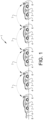
- Fig. 1 shows a vehicle platoon 1 having a lead vehicle 2 and a plurality of following vehicles 3.
- the lead vehicle 2 and the following vehicles 3 are individual vehicles but driven together as a group or convoy.
- the following vehicles 3 are positioned in a line after the lead vehicle 2.
- the driving direction is indicated with an arrow 8.
- the lead vehicle 2 is at least partly controlled by an operator of the lead vehicle.
- the following vehicles 3 of the vehicle platoon are suitably automatically controlled without any driver assistance.
- the following vehicles 3 are controlled to follow the lead vehicle 2 or the vehicle closest to the front, such that when the speed of the lead vehicle 2 is increased/decreased the speed of the following vehicles 3 is increased/decreased correspondingly for maintaining or achieving the desired distances and time gaps between the vehicles. Further, when the lead vehicle 2 is changing driving direction, a following vehicle 3 will also change driving direction and follow the lead vehicle or rather the vehicle closest to the front.
- each vehicle can be provided with any suitable sensor equipment 4 for receiving information about the environment, and a control unit 5 for controlling the vehicle.
- the sensor equipment can give information about at least the vehicle closest to the front, but preferably the sensor equipment is covering 360 degrees around the vehicle for obtaining the information that is required for longitudinal and lateral control of the vehicle.
- Such sensor equipment 4 may comprise lidar, radar and ultrasonic sensors, cameras, etc.
- the information received by the sensor equipment is used by the control unit 5 for controlling the driving behaviour of the vehicle.
- maps, GPS, etc. can be used for determining the current position of a vehicle platoon or an individual vehicle of a vehicle platoon.
- each vehicle 2, 3 is provided with a communication unit 6 for communicating with one or more of the other vehicles of the vehicle platoon 1.
- a communication unit 6 may comprise any suitable components for establish communication between the vehicles.
- the communication unit 6 may comprise a transmitter and a receiver based on radio waves or microwaves.
- each vehicle can be part of a local network for communication 7 between the vehicles of the vehicle platoon 1.
- control signals can be transmitted from one vehicle to another vehicle.
- the control signals received are then used by the control unit 5 arranged on the vehicle for controlling the driving behaviour of the vehicle.
- Such control signals received by the following vehicles 3 are preferably at least initially transmitted by the lead vehicle 2.
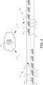
- Fig. 2 shows two vehicle platoons 1a, 1b driving in different lanes of a road.
- Each vehicle platoon 1a, 1b of the current traffic system is also part of a central network for communication 9 between the vehicle platoon 1a, 1b and a central control unit 10.
- control signals can be transmitted from the central control unit 10 to a vehicle platoon 1a, 1b for controlling the driving behaviour of the vehicle platoon.
- Such control signals are preferably received by the lead vehicle 2a, 2b of the vehicle platoon, but could also be received by one or more of the following vehicles 3 of the vehicle platoon.
- the central control unit 10 can be part of a server of a wireless network, such as Internet, for cloud computing.
- the central control unit 10 and the local control unit 5 arranged on a vehicle may comprise one or more microprocessors and/or one or more memory devices or any other components for executing computer programs to perform the method described hereinafter.
- the central control unit and/or the local control unit is preferably provided with a computer program comprising program code means for performing the steps of any example embodiment of the method described hereinafter.
- both the control unit 5 of the vehicle and the central control unit 10 are used in cooperation.
- sensors can be arranged in the environment to the current road where the vehicle platoon is driven. These sensors may provide information to be received by the control unit 5 and/or the central control unit 10. Such sensors could be a complement to the sensors of the vehicles, giving further information and/or redundancy to the system.
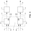
- Fig. 3 is a schematic view of a control unit 20a for controlling a brake 21 of a lead vehicle of a vehicle platoon.
- a brake request signal 22 is input to the control unit 20a comprising brake maps 29a, 29a'.
- a brake force signal 23 is output from the control unit 20 and input to the brake 21.
- the brake force signal 23 is used for controlling braking of the vehicle.
- the brake 21 can be any suitable equipment such as a disc brake, a part of a drive line, engine braking, etc., for generating a brake force braking the vehicle.
- the brake request signal 22 is generated by an action of the the operator of the lead vehicle, for example by means of pushing a brake pedal.
- the brake request signal 22 can be a function of the brake pedal position.
- Fig. 3 The lower part of Fig. 3 is a schematic view of a control unit 20b for controlling a drive line 24 of a lead vehicle of a vehicle platoon.
- An acceleration request signal 25 is input to the control unit 20b comprising acceleration maps 29b, 29b'.
- a traction force signal 26 is output from the control unit 20b.
- the traction force signal 26 is used for controlling acceleration of the vehicle.
- the drive line 24 can comprise any suitable equipment such as an engine, an electric motor, etc., for generating a traction force accelerating the vehicle.
- the acceleration request signal 25 is generated by an action of the operator of the lead vehicle, for example by means of pushing an acceleration pedal.
- the acceleration request signal 25 can be a function of the acceleration pedal position.
- control unit 20a for controlling the brake and the control unit 20b for controlling the drive line could be one and the same control unit or at least be integrated in the same unit.
- control unit 20 hereinafter when referring to the control unit 20a for controlling the brake and/or the control unit 20b for controlling the drive line.
- control unit 20 can be included in the control unit 5 arranged on the vehicle.
- the control unit 20 is configured to provide a first mode and a second mode for the lead vehicle.
- the first mode and the second mode are achieved by using a first brake map 29a for the first mode and a second brake map 29a' for the second mode for controlling the brake 21 of the lead vehicle.
- the first brake map 29a gives a lower brake force 27 on the lead vehicle 2 than the second brake map 29a' for equal brake requests 22.
- the first mode and the second mode are achieved by using a first acceleration map 29b for the first mode and a second acceleration map 29b' for the second mode for controlling the drive unit 24 of the lead vehicle.
- the first acceleration map 29b gives a lower traction force 28 on the lead vehicle 2 than the second acceleration map 29b' for equal acceleration requests 25.
- the lower brake force output and the lower traction force output for the first mode in comparison to the second mode is applied for at least a significant part of the brake request interval and the acceleration request interval, respectively.
- Fig. 4 shows an example of a lookup table of a brake map.
- the horizontal axis represents the position X of the brake pedal and the vertical axis represents the brake force BF.
- the upper line 30 shows brake force as a function of brake pedal position for the second mode
- the line 31 below shows brake force as a function of brake pedal position for the first mode.
- the brake force BF2 for the second mode is larger than the brake force BF1 for the first mode.
- the first brake map can give a lower brake force change speed than the second brake map for equal brake requests 22.
- the response is slower in the first mode than in the second mode.
- Fig. 5 shows an example of a lookup table for a brake map.
- the horizontal axis represents time T and the vertical axis represents the brake force BF.
- the upper line 32 shows brake force as a function of time for the second mode
- the line 33 below shows brake force as a function of time for the first mode.
- the graph illustrates that at a time point T 0 , the brake pedal has been moved a certain distance ⁇ x. Then, the brake force is increased during ⁇ T from To to T 1 .
- the change in brake force ⁇ BF2 for the second mode is larger than the change in brake force ⁇ BF1 for the first mode.
- the brake force change speed is higher in the second mode than in the first mode.
- the first accelerating map can give a lower traction force change speed than the second acceleration map for equal acceleration requests.
- the response is slower in the first mode than in the second mode.
- the first mode can be a comfort mode providing smoother driving and reduced energy consumption.
- the first mode can be selected by the operator of the lead vehicle or automatically activated as a default mode.
- the control unit 20 is further configured to shift from the first mode to the second mode when receiving an input signal 60a, 60b indicating that an operator of the lead vehicle 2 has performed a predetermined driving action. See Fig. 3 .
- the input signal 60a, 60b can be the same signal or part of the brake request signal 22 or the acceleration request signal 25, or be a separate signal.
- the second mode can be a safety mode in which the manoeuvrability of the vehicle is prioritized over comfort and energy consumption.
- the predetermined driving action is suitably such an action which the operator is supposed to perform in case of a critical situation where maximal deceleration or acceleration is desired.
- such driving actions can be one or more of the following cases: a brake pedal position of the lead vehicle is changed with a speed exceeding a predetermined threshold value, a brake pedal speed change of the lead vehicle exceeds a predetermined threshold value, and a brake pedal of the lead vehicle is moved a distance exceeding a predetermined threshold value.
- driving actions can be one or more of the following cases: an acceleration pedal position of the lead vehicle is changed with a speed exceeding a predetermined threshold value, an acceleration pedal speed change of the lead vehicle exceeds a predetermined threshold value, and an acceleration pedal of the lead vehicle is moved a distance exceeding a predetermined threshold value.
- shifting from the first mode to the second mode can also be performed automatically by a control unit 5 arranged on the vehicle or a central control unit 10 without any action from the operator.
- the increased risk level can be detected by any sensor equipment of a vehicle of the vehicle platoon or identified by any external system providing information about the current traffic situation.
- the method comprises the steps of providing a first mode and a second mode for driving the lead vehicle, by using a first brake map 29a for the first mode and a second brake map 29a' for the second mode for braking the lead vehicle 2.
- the first brake map 29a gives a lower brake force on the lead vehicle than the second brake map 29a' for equal brake requests 22.
- the first mode and the second mode is achieved by using a first acceleration map 29b for the first mode and a second acceleration map 29b' for the second mode for accelerating the lead vehicle 2.
- the first acceleration map 29b gives a lower traction force on the lead vehicle than the second acceleration map 29b' for equal acceleration requests 25.
- the method also comprises the step of shifting from the first mode to the second mode when an operator of the lead vehicle 2 has performed a predetermined driving action.
- the method can comprise the step of communicating to one or more of the plurality of following vehicles 3 that a shift from the first mode to the second mode for the lead vehicle 2 has taken place.
- This information can be used by a control unit 5 of a following vehicle for adapting the control system response of the following vehicle to the current mode of the lead vehicle.
- a higher or faster control system response of the following vehicle is suitably used.
- Figs. 6 and 7 show two examples of graphs illustrating vehicle output and pedal position when shifting from the first mode to the second mode.
- the vehicle output can be brake force or traction force (acceleration) and the pedal can be a brake pedal or an acceleration pedal.
- the graph shows vehicle output VOP and pedal position X versus time T.
- a first curve 40 which is illustrated by a dotted line, shows the pedal position as a function of the time.
- a second curve 41 which is illustrated by a solid line, shows the vehicle output as a function of time.
- the first mode is used and the vehicle output VOP varies with the time (and the pedal position) as indicated by the curve portion 41a provided in the first mode.
- the second mode is used and the vehicle output VOP varies with the time (and the pedal position) as indicated by the curve portion 41b provided in the second mode.
- the vehicle output is gradually increased when shifting from the first mode to the second mode.
- the shifting from the first mode to the second mode can be induced in any way as previously described hereinabove.
- the graph shows vehicle output VOP and pedal position X versus time T.
- a first curve 50 which is illustrated by a dotted line, shows the pedal position as a function of the time.
- a second curve 51 which is illustrated by a solid line, shows the vehicle output as a function of time.
- the first mode is used and the vehicle output VOP varies with the time (and the pedal position) as indicated by the curve portion 51a provided in the first mode.
- the second mode is used and the vehicle output VOP varies with the time (and the pedal position) as indicated by the curve portion 51b provided in the second mode.
- the vehicle output is substantially instantaneously increased when shifting from the first mode to the second mode.
- the shifting from the first mode to the second mode can be induced in any way as previously described hereinabove.
- control unit can be configured accordingly.
Landscapes
- Engineering & Computer Science (AREA)
- Automation & Control Theory (AREA)
- Transportation (AREA)
- Mechanical Engineering (AREA)
- Physics & Mathematics (AREA)
- General Physics & Mathematics (AREA)
- Control Of Driving Devices And Active Controlling Of Vehicle (AREA)
- Regulating Braking Force (AREA)
Claims (14)
- Procédé pour commander un peloton de véhicules (1) ayant un véhicule de tête (2) et une pluralité de véhicules (3) suivant le véhicule de tête, le procédé comprenant les étapes de fourniture d'un premier mode et d'un second mode pour commander le véhicule de tête (2), à l'aide d'une première carte de freinage (29a) pour le premier mode et d'une seconde carte de freinage (29a') pour le second mode pour freiner le véhicule de tête (2), la première carte de freinage donnant une force de freinage inférieure (27) sur le véhicule de tête par rapport à la seconde carte de freinage pour des demandes de freinage égales (22), et/ou à l'aide d'une première carte d'accélération (29b) pour le premier mode et d'une seconde carte d'accélération (29b') pour le second mode pour accélérer le véhicule de tête (2), la première carte d'accélération donnant une force de traction inférieure (28) sur le véhicule de tête par rapport à la seconde carte d'accélération pour des demandes d'accélération égales (25), et le passage du premier mode au second mode lorsqu'un opérateur du véhicule de tête (2) a effectué une action de conduite prédéterminée, et la communication à un ou plusieurs de la pluralité de véhicules suivants (3) qu'un passage du premier mode au second mode pour le véhicule de tête (2) a eu lieu.
- Procédé selon la revendication 1, caractérisé par la fourniture de la première carte de freinage (29a) pour le premier mode et la seconde carte de freinage (29a') pour le second mode de freinage du véhicule de tête (2), la première carte de freinage donnant une vitesse de changement de force de freinage inférieure à la seconde carte de freinage pour des demandes de freinage égales.
- Procédé selon la revendication 1 ou 2, caractérisé par la fourniture de la première carte d'accélération (29b) pour le premier mode et la seconde carte d'accélération (29b') pour le second mode pour accélérer le véhicule de tête (2), la première carte d'accélération donnant une vitesse de changement de force de traction inférieure à la seconde carte d'accélération pour des demandes d'accélération égales.
- Procédé selon une quelconque revendication précédente, caractérisé par le passage du premier mode au second mode lorsqu'une position de la pédale de frein du véhicule de tête (2) est modifiée avec une vitesse dépassant une valeur seuil prédéterminée.
- Procédé selon une quelconque revendication précédente, caractérisé par le passage du premier mode au second mode lorsqu'un changement de vitesse de pédale de frein du véhicule de tête (2) dépasse une valeur seuil prédéterminée.
- Procédé selon une quelconque revendication précédente, caractérisé par le passage du premier mode au second mode lorsqu'une pédale de frein du véhicule de tête (2) est déplacée d'une distance dépassant une valeur seuil prédéterminée.
- Procédé selon une quelconque revendication précédente, caractérisé par le passage du premier mode au second mode lorsqu'une position de pédale d'accélérateur du véhicule de tête (2) est modifiée avec une vitesse dépassant une valeur seuil prédéterminée.
- Procédé selon une quelconque revendication précédente, caractérisé par le passage du premier mode au second mode lorsqu'un changement de vitesse de pédale d'accélérateur du véhicule de tête (2) dépasse une valeur seuil prédéterminée.
- Procédé selon une quelconque revendication précédente, caractérisé par le passage du premier mode au second mode lorsqu'une pédale d'accélérateur du véhicule de tête (2) est déplacée d'une distance dépassant une valeur seuil prédéterminée.
- Procédé selon une quelconque revendication précédente, caractérisé par le passage du premier mode au second mode pour le véhicule de tête (2) lorsqu'un niveau de risque accru pour un véhicule (2, 3) du peloton de véhicules (1) ou du peloton de véhicules entier (1) est identifié.
- Unité de commande (20) pour commander un peloton de véhicules (1) ayant un véhicule de tête (2) et une pluralité de véhicules (3) suivant le véhicule de tête, l'unité de commande (20) est configurée pour fournir un premier mode et un second mode pour le véhicule de tête (2), à l'aide d'une première carte de freinage (29a) pour le premier mode et d'une seconde carte de freinage (29a') pour le second mode pour commander un frein (21) du véhicule de tête (2), la première carte de freinage (29a) donnant une force de freinage inférieure sur le véhicule de tête (2) par rapport à la seconde carte de freinage (29a') pour des demandes de freinage égales (22), et/ou à l'aide d'une première carte d'accélération (29b) pour le premier mode et d'une seconde carte d'accélération (29b') pour le second mode de commande d'un groupe motopropulseur (24) du véhicule de tête (2), la première carte d'accélération (29b) donnant une force de traction inférieure sur le véhicule de tête (2) par rapport à la seconde carte d'accélération (29b') pour des demandes d'accélération égales (25), et l'unité de commande (20) est configurée pour passer du premier mode au second mode lors de la réception d'un signal d'entrée (60a, 60b) indiquant qu'un opérateur du véhicule de tête (2) a exécuté une action de conduite prédéterminée, et pour communiquer à un ou plusieurs de la pluralité de véhicules suivants (3) qu'un passage du premier mode au second mode pour le véhicule de tête (2) a eu lieu.
- Programme informatique comprenant un moyen de code de programme pour exécuter un procédé selon l'une quelconque des revendications 1 à 10.
- Véhicule de tête (2) pour un peloton de véhicules (1), le véhicule de tête (2) comprenant une unité de commande (20) selon la revendication 11.
- Peloton de véhicules (1) comprenant un véhicule de tête (2) et une pluralité de véhicules suivants (3), le véhicule de tête (2) comprenant une unité de commande (20) selon la revendication 11.
Priority Applications (4)
| Application Number | Priority Date | Filing Date | Title |
|---|---|---|---|
| EP19199474.8A EP3798075B1 (fr) | 2019-09-25 | 2019-09-25 | Procédé pour commander un peloton de véhicules |
| PCT/CN2020/115758 WO2021057583A1 (fr) | 2019-09-25 | 2020-09-17 | Procédé pour conduire un peloton de véhicules |
| CN202080066021.7A CN114423660A (zh) | 2019-09-25 | 2020-09-17 | 用于行驶车辆队列的方法 |
| US17/697,441 US20220203988A1 (en) | 2019-09-25 | 2022-03-17 | Method for driving a vehicle platoon |
Applications Claiming Priority (1)
| Application Number | Priority Date | Filing Date | Title |
|---|---|---|---|
| EP19199474.8A EP3798075B1 (fr) | 2019-09-25 | 2019-09-25 | Procédé pour commander un peloton de véhicules |
Publications (2)
| Publication Number | Publication Date |
|---|---|
| EP3798075A1 EP3798075A1 (fr) | 2021-03-31 |
| EP3798075B1 true EP3798075B1 (fr) | 2023-08-02 |
Family
ID=68066742
Family Applications (1)
| Application Number | Title | Priority Date | Filing Date |
|---|---|---|---|
| EP19199474.8A Active EP3798075B1 (fr) | 2019-09-25 | 2019-09-25 | Procédé pour commander un peloton de véhicules |
Country Status (4)
| Country | Link |
|---|---|
| US (1) | US20220203988A1 (fr) |
| EP (1) | EP3798075B1 (fr) |
| CN (1) | CN114423660A (fr) |
| WO (1) | WO2021057583A1 (fr) |
Families Citing this family (2)
| Publication number | Priority date | Publication date | Assignee | Title |
|---|---|---|---|---|
| CN115951666A (zh) * | 2019-12-24 | 2023-04-11 | 北京图森智途科技有限公司 | 自动驾驶车队中的车辆控制方法、车载装置及车辆 |
| CN113341726B (zh) * | 2021-06-18 | 2022-05-27 | 江南大学 | 一种多质点车辆队列行驶系统的迭代学习控制方法 |
Family Cites Families (22)
| Publication number | Priority date | Publication date | Assignee | Title |
|---|---|---|---|---|
| JPH09263233A (ja) * | 1996-03-27 | 1997-10-07 | Denso Corp | 車両用ブレーキ装置 |
| JP3716490B2 (ja) * | 1996-04-05 | 2005-11-16 | トヨタ自動車株式会社 | 制動力制御装置 |
| JP4400551B2 (ja) * | 2005-11-11 | 2010-01-20 | トヨタ自動車株式会社 | 車両の制御装置 |
| JP4345819B2 (ja) * | 2007-01-19 | 2009-10-14 | トヨタ自動車株式会社 | エコドライブ支援装置、エコドライブ支援方法 |
| JP2011148342A (ja) * | 2010-01-19 | 2011-08-04 | Toyota Motor Corp | 車両制御装置 |
| WO2012164717A1 (fr) * | 2011-06-02 | 2012-12-06 | トヨタ自動車株式会社 | Dispositif de commande de véhicule |
| US8788113B2 (en) * | 2011-06-13 | 2014-07-22 | Ford Global Technologies, Llc | Vehicle driver advisory system and method |
| US9645579B2 (en) * | 2011-07-06 | 2017-05-09 | Peloton Technology, Inc. | Vehicle platooning systems and methods |
| SE537958C2 (sv) * | 2012-09-24 | 2015-12-08 | Scania Cv Ab | Förfarande, mätanordning och styrenhet för anpassning av fordonstågsstyrning |
| KR101543160B1 (ko) * | 2014-05-08 | 2015-08-07 | 현대자동차주식회사 | 속도 연동형 브레이크 제동력 제어 방법 |
| JP6428712B2 (ja) * | 2016-06-09 | 2018-11-28 | マツダ株式会社 | 運転支援装置 |
| US10049328B2 (en) * | 2016-10-13 | 2018-08-14 | Baidu Usa Llc | Group driving style learning framework for autonomous vehicles |
| US10281926B2 (en) * | 2017-01-23 | 2019-05-07 | Bendix Commercial Vehicle Systems Llc | Apparatus and method for controlling vehicles in a platoon |
| CN110191833B (zh) * | 2017-01-23 | 2022-02-22 | 本田技研工业株式会社 | 车辆控制系统、车辆控制方法及存储介质 |
| EP3385561B1 (fr) * | 2017-03-31 | 2020-04-15 | Honda Motor Co., Ltd. | Dispositif de transmission de puissance pour véhicule |
| EP3418843B1 (fr) * | 2017-06-23 | 2021-03-17 | Volkswagen Aktiengesellschaft | Concept de coordination d'un freinage d'urgence d'un peloton de véhicules couplé de manière communicative |
| US10814844B2 (en) * | 2017-09-15 | 2020-10-27 | Bendix Commercial Vehicle Systems Llc | Braking controller and method using verification of reported trailer capabilities |
| US10549739B2 (en) * | 2017-09-15 | 2020-02-04 | Bendix Commercial Vehicle Systems Llc | Towing vehicle controller using trailer braking strategy and trailer braking control method |
| KR102383436B1 (ko) * | 2017-12-01 | 2022-04-07 | 현대자동차주식회사 | 군집주행 제어 장치 및 방법 |
| DE102018001055A1 (de) * | 2017-12-08 | 2019-06-13 | Knorr-Bremse Systeme für Nutzfahrzeuge GmbH | Verfahren zur Auslösung eines selbsttätigen Notbremsvorgangs bei einer Fahrzeugkolonne |
| JP6992484B2 (ja) * | 2017-12-19 | 2022-01-13 | 株式会社デンソー | 燃料ポンプ制御装置 |
| JP7368975B2 (ja) * | 2019-07-26 | 2023-10-25 | 日立Astemo株式会社 | 車両制御装置、車両制御方法、及び車両追従走行システム |
-
2019
- 2019-09-25 EP EP19199474.8A patent/EP3798075B1/fr active Active
-
2020
- 2020-09-17 WO PCT/CN2020/115758 patent/WO2021057583A1/fr active Application Filing
- 2020-09-17 CN CN202080066021.7A patent/CN114423660A/zh active Pending
-
2022
- 2022-03-17 US US17/697,441 patent/US20220203988A1/en active Pending
Also Published As
| Publication number | Publication date |
|---|---|
| CN114423660A (zh) | 2022-04-29 |
| WO2021057583A1 (fr) | 2021-04-01 |
| EP3798075A1 (fr) | 2021-03-31 |
| US20220203988A1 (en) | 2022-06-30 |
Similar Documents
| Publication | Publication Date | Title |
|---|---|---|
| JP6330731B2 (ja) | 車両の制御装置 | |
| US10239526B2 (en) | Adaptive cruise control system | |
| US20220105925A1 (en) | One pedal driving | |
| KR101679273B1 (ko) | 속력 제어 방법 및 시스템 | |
| JP6048457B2 (ja) | 車両走行制御装置 | |
| CN108189837B (zh) | 车辆控制装置 | |
| US20220203988A1 (en) | Method for driving a vehicle platoon | |
| US9452755B2 (en) | Vehicle travel control apparatus | |
| JP6308167B2 (ja) | 車両の制御装置 | |
| CN110431058B (zh) | 行驶控制装置、车辆及行驶控制方法 | |
| EP2000380A2 (fr) | Dispositif et procede de commande de deplacement de vehicule | |
| US20210213967A1 (en) | Driving assistance apparatus | |
| JP7052692B2 (ja) | 隊列走行システム | |
| JP2016215921A (ja) | 車両の制御装置 | |
| JP2007522021A (ja) | 自動車のための距離制御付き速度制限方法及び速度制限装置 | |
| JP2023071521A (ja) | 駆動力制御装置 | |
| CN114080339A (zh) | 车辆控制装置、车辆控制方法、以及车辆追随行驶系统 | |
| JP2021138245A (ja) | 車両制御装置及び車両制御方法 | |
| JP2008044421A (ja) | 車両走行制御装置 | |
| US20240101114A1 (en) | Vehicle driving mode | |
| EP4342757A1 (fr) | Commande de modes et d'opérations de conduite pour véhicules autonomes | |
| JP7329142B2 (ja) | 車両制御装置 | |
| US20230078907A1 (en) | Driving assistance device | |
| US20240140410A1 (en) | Vehicle deceleration assistance apparatus | |
| JP5402745B2 (ja) | 走行制御装置 |
Legal Events
| Date | Code | Title | Description |
|---|---|---|---|
| PUAI | Public reference made under article 153(3) epc to a published international application that has entered the european phase |
Free format text: ORIGINAL CODE: 0009012 |
|
| STAA | Information on the status of an ep patent application or granted ep patent |
Free format text: STATUS: REQUEST FOR EXAMINATION WAS MADE |
|
| 17P | Request for examination filed |
Effective date: 20190925 |
|
| AK | Designated contracting states |
Kind code of ref document: A1 Designated state(s): AL AT BE BG CH CY CZ DE DK EE ES FI FR GB GR HR HU IE IS IT LI LT LU LV MC MK MT NL NO PL PT RO RS SE SI SK SM TR |
|
| AX | Request for extension of the european patent |
Extension state: BA ME |
|
| GRAP | Despatch of communication of intention to grant a patent |
Free format text: ORIGINAL CODE: EPIDOSNIGR1 |
|
| STAA | Information on the status of an ep patent application or granted ep patent |
Free format text: STATUS: GRANT OF PATENT IS INTENDED |
|
| INTG | Intention to grant announced |
Effective date: 20230227 |
|
| GRAS | Grant fee paid |
Free format text: ORIGINAL CODE: EPIDOSNIGR3 |
|
| GRAA | (expected) grant |
Free format text: ORIGINAL CODE: 0009210 |
|
| STAA | Information on the status of an ep patent application or granted ep patent |
Free format text: STATUS: THE PATENT HAS BEEN GRANTED |
|
| AK | Designated contracting states |
Kind code of ref document: B1 Designated state(s): AL AT BE BG CH CY CZ DE DK EE ES FI FR GB GR HR HU IE IS IT LI LT LU LV MC MK MT NL NO PL PT RO RS SE SI SK SM TR |
|
| REG | Reference to a national code |
Ref country code: GB Ref legal event code: FG4D |
|
| REG | Reference to a national code |
Ref country code: CH Ref legal event code: EP |
|
| REG | Reference to a national code |
Ref country code: DE Ref legal event code: R096 Ref document number: 602019033921 Country of ref document: DE |
|
| REG | Reference to a national code |
Ref country code: IE Ref legal event code: FG4D |
|
| PGFP | Annual fee paid to national office [announced via postgrant information from national office to epo] |
Ref country code: GB Payment date: 20230810 Year of fee payment: 5 |
|
| REG | Reference to a national code |
Ref country code: LT Ref legal event code: MG9D |
|
| PGFP | Annual fee paid to national office [announced via postgrant information from national office to epo] |
Ref country code: FR Payment date: 20230808 Year of fee payment: 5 Ref country code: DE Payment date: 20230808 Year of fee payment: 5 |
|
| REG | Reference to a national code |
Ref country code: NL Ref legal event code: MP Effective date: 20230802 |
|
| REG | Reference to a national code |
Ref country code: AT Ref legal event code: MK05 Ref document number: 1594374 Country of ref document: AT Kind code of ref document: T Effective date: 20230802 |
|
| PG25 | Lapsed in a contracting state [announced via postgrant information from national office to epo] |
Ref country code: IS Free format text: LAPSE BECAUSE OF FAILURE TO SUBMIT A TRANSLATION OF THE DESCRIPTION OR TO PAY THE FEE WITHIN THE PRESCRIBED TIME-LIMIT Effective date: 20231202 |
|
| PG25 | Lapsed in a contracting state [announced via postgrant information from national office to epo] |
Ref country code: SE Free format text: LAPSE BECAUSE OF FAILURE TO SUBMIT A TRANSLATION OF THE DESCRIPTION OR TO PAY THE FEE WITHIN THE PRESCRIBED TIME-LIMIT Effective date: 20230802 Ref country code: RS Free format text: LAPSE BECAUSE OF FAILURE TO SUBMIT A TRANSLATION OF THE DESCRIPTION OR TO PAY THE FEE WITHIN THE PRESCRIBED TIME-LIMIT Effective date: 20230802 Ref country code: PT Free format text: LAPSE BECAUSE OF FAILURE TO SUBMIT A TRANSLATION OF THE DESCRIPTION OR TO PAY THE FEE WITHIN THE PRESCRIBED TIME-LIMIT Effective date: 20231204 Ref country code: NO Free format text: LAPSE BECAUSE OF FAILURE TO SUBMIT A TRANSLATION OF THE DESCRIPTION OR TO PAY THE FEE WITHIN THE PRESCRIBED TIME-LIMIT Effective date: 20231102 Ref country code: NL Free format text: LAPSE BECAUSE OF FAILURE TO SUBMIT A TRANSLATION OF THE DESCRIPTION OR TO PAY THE FEE WITHIN THE PRESCRIBED TIME-LIMIT Effective date: 20230802 Ref country code: LV Free format text: LAPSE BECAUSE OF FAILURE TO SUBMIT A TRANSLATION OF THE DESCRIPTION OR TO PAY THE FEE WITHIN THE PRESCRIBED TIME-LIMIT Effective date: 20230802 Ref country code: LT Free format text: LAPSE BECAUSE OF FAILURE TO SUBMIT A TRANSLATION OF THE DESCRIPTION OR TO PAY THE FEE WITHIN THE PRESCRIBED TIME-LIMIT Effective date: 20230802 Ref country code: IS Free format text: LAPSE BECAUSE OF FAILURE TO SUBMIT A TRANSLATION OF THE DESCRIPTION OR TO PAY THE FEE WITHIN THE PRESCRIBED TIME-LIMIT Effective date: 20231202 Ref country code: HR Free format text: LAPSE BECAUSE OF FAILURE TO SUBMIT A TRANSLATION OF THE DESCRIPTION OR TO PAY THE FEE WITHIN THE PRESCRIBED TIME-LIMIT Effective date: 20230802 Ref country code: FI Free format text: LAPSE BECAUSE OF FAILURE TO SUBMIT A TRANSLATION OF THE DESCRIPTION OR TO PAY THE FEE WITHIN THE PRESCRIBED TIME-LIMIT Effective date: 20230802 Ref country code: AT Free format text: LAPSE BECAUSE OF FAILURE TO SUBMIT A TRANSLATION OF THE DESCRIPTION OR TO PAY THE FEE WITHIN THE PRESCRIBED TIME-LIMIT Effective date: 20230802 |
|
| PG25 | Lapsed in a contracting state [announced via postgrant information from national office to epo] |
Ref country code: PL Free format text: LAPSE BECAUSE OF FAILURE TO SUBMIT A TRANSLATION OF THE DESCRIPTION OR TO PAY THE FEE WITHIN THE PRESCRIBED TIME-LIMIT Effective date: 20230802 |
|
| PG25 | Lapsed in a contracting state [announced via postgrant information from national office to epo] |
Ref country code: ES Free format text: LAPSE BECAUSE OF FAILURE TO SUBMIT A TRANSLATION OF THE DESCRIPTION OR TO PAY THE FEE WITHIN THE PRESCRIBED TIME-LIMIT Effective date: 20230802 |
|
| PG25 | Lapsed in a contracting state [announced via postgrant information from national office to epo] |
Ref country code: SM Free format text: LAPSE BECAUSE OF FAILURE TO SUBMIT A TRANSLATION OF THE DESCRIPTION OR TO PAY THE FEE WITHIN THE PRESCRIBED TIME-LIMIT Effective date: 20230802 Ref country code: RO Free format text: LAPSE BECAUSE OF FAILURE TO SUBMIT A TRANSLATION OF THE DESCRIPTION OR TO PAY THE FEE WITHIN THE PRESCRIBED TIME-LIMIT Effective date: 20230802 Ref country code: ES Free format text: LAPSE BECAUSE OF FAILURE TO SUBMIT A TRANSLATION OF THE DESCRIPTION OR TO PAY THE FEE WITHIN THE PRESCRIBED TIME-LIMIT Effective date: 20230802 Ref country code: EE Free format text: LAPSE BECAUSE OF FAILURE TO SUBMIT A TRANSLATION OF THE DESCRIPTION OR TO PAY THE FEE WITHIN THE PRESCRIBED TIME-LIMIT Effective date: 20230802 Ref country code: DK Free format text: LAPSE BECAUSE OF FAILURE TO SUBMIT A TRANSLATION OF THE DESCRIPTION OR TO PAY THE FEE WITHIN THE PRESCRIBED TIME-LIMIT Effective date: 20230802 Ref country code: CZ Free format text: LAPSE BECAUSE OF FAILURE TO SUBMIT A TRANSLATION OF THE DESCRIPTION OR TO PAY THE FEE WITHIN THE PRESCRIBED TIME-LIMIT Effective date: 20230802 Ref country code: SK Free format text: LAPSE BECAUSE OF FAILURE TO SUBMIT A TRANSLATION OF THE DESCRIPTION OR TO PAY THE FEE WITHIN THE PRESCRIBED TIME-LIMIT Effective date: 20230802 |
|
| REG | Reference to a national code |
Ref country code: CH Ref legal event code: PL |
|
| PG25 | Lapsed in a contracting state [announced via postgrant information from national office to epo] |
Ref country code: LU Free format text: LAPSE BECAUSE OF NON-PAYMENT OF DUE FEES Effective date: 20230925 |