EP3796872B1 - A device for the in-situ delivery of heart valve prostheses - Google Patents
A device for the in-situ delivery of heart valve prostheses Download PDFInfo
- Publication number
- EP3796872B1 EP3796872B1 EP18732478.5A EP18732478A EP3796872B1 EP 3796872 B1 EP3796872 B1 EP 3796872B1 EP 18732478 A EP18732478 A EP 18732478A EP 3796872 B1 EP3796872 B1 EP 3796872B1
- Authority
- EP
- European Patent Office
- Prior art keywords
- deployment
- pair
- drive
- shaft
- axial
- Prior art date
- Legal status (The legal status is an assumption and is not a legal conclusion. Google has not performed a legal analysis and makes no representation as to the accuracy of the status listed.)
- Active
Links
Images




Classifications
-
- A—HUMAN NECESSITIES
- A61—MEDICAL OR VETERINARY SCIENCE; HYGIENE
- A61F—FILTERS IMPLANTABLE INTO BLOOD VESSELS; PROSTHESES; DEVICES PROVIDING PATENCY TO, OR PREVENTING COLLAPSING OF, TUBULAR STRUCTURES OF THE BODY, e.g. STENTS; ORTHOPAEDIC, NURSING OR CONTRACEPTIVE DEVICES; FOMENTATION; TREATMENT OR PROTECTION OF EYES OR EARS; BANDAGES, DRESSINGS OR ABSORBENT PADS; FIRST-AID KITS
- A61F2/00—Filters implantable into blood vessels; Prostheses, i.e. artificial substitutes or replacements for parts of the body; Appliances for connecting them with the body; Devices providing patency to, or preventing collapsing of, tubular structures of the body, e.g. stents
- A61F2/02—Prostheses implantable into the body
- A61F2/24—Heart valves ; Vascular valves, e.g. venous valves; Heart implants, e.g. passive devices for improving the function of the native valve or the heart muscle; Transmyocardial revascularisation [TMR] devices; Valves implantable in the body
- A61F2/2427—Devices for manipulating or deploying heart valves during implantation
- A61F2/2436—Deployment by retracting a sheath
-
- A—HUMAN NECESSITIES
- A61—MEDICAL OR VETERINARY SCIENCE; HYGIENE
- A61F—FILTERS IMPLANTABLE INTO BLOOD VESSELS; PROSTHESES; DEVICES PROVIDING PATENCY TO, OR PREVENTING COLLAPSING OF, TUBULAR STRUCTURES OF THE BODY, e.g. STENTS; ORTHOPAEDIC, NURSING OR CONTRACEPTIVE DEVICES; FOMENTATION; TREATMENT OR PROTECTION OF EYES OR EARS; BANDAGES, DRESSINGS OR ABSORBENT PADS; FIRST-AID KITS
- A61F2/00—Filters implantable into blood vessels; Prostheses, i.e. artificial substitutes or replacements for parts of the body; Appliances for connecting them with the body; Devices providing patency to, or preventing collapsing of, tubular structures of the body, e.g. stents
- A61F2/02—Prostheses implantable into the body
- A61F2/24—Heart valves ; Vascular valves, e.g. venous valves; Heart implants, e.g. passive devices for improving the function of the native valve or the heart muscle; Transmyocardial revascularisation [TMR] devices; Valves implantable in the body
- A61F2/2427—Devices for manipulating or deploying heart valves during implantation
-
- A—HUMAN NECESSITIES
- A61—MEDICAL OR VETERINARY SCIENCE; HYGIENE
- A61F—FILTERS IMPLANTABLE INTO BLOOD VESSELS; PROSTHESES; DEVICES PROVIDING PATENCY TO, OR PREVENTING COLLAPSING OF, TUBULAR STRUCTURES OF THE BODY, e.g. STENTS; ORTHOPAEDIC, NURSING OR CONTRACEPTIVE DEVICES; FOMENTATION; TREATMENT OR PROTECTION OF EYES OR EARS; BANDAGES, DRESSINGS OR ABSORBENT PADS; FIRST-AID KITS
- A61F2/00—Filters implantable into blood vessels; Prostheses, i.e. artificial substitutes or replacements for parts of the body; Appliances for connecting them with the body; Devices providing patency to, or preventing collapsing of, tubular structures of the body, e.g. stents
- A61F2/95—Instruments specially adapted for placement or removal of stents or stent-grafts
- A61F2/9517—Instruments specially adapted for placement or removal of stents or stent-grafts handle assemblies therefor
Definitions
- the present disclosure relates to devices for the in-situ delivery of heart valve prostheses.
- Prior art examples in this field include, i.a., documents WO 2014/121280 A2 , WO 2009/091509 A1 , and WO 2017/195125 A1 .
- Expandable heart valve prostheses typically include an expandable and collapsible anchoring structure or armature, capable of supporting and fixing the valve prosthesis in the implantation position, and prosthetic valve elements, generally in the form of leaflets or flaps, which are stably connected to the anchoring structure and able to regulate blood flow.
- expandable prosthetic valves enable implantation using traditional (surgical), minimally invasive, or sutureless techniques.
- Exemplary applications for such an expandable valve prosthesis include aortic and pulmonary valve replacement.
- Certain heart valve prostheses feature an armature that requires a delivery instrument with multiple deployment elements in order for it to be kept in a radially contracted condition properly, as well as to be properly deployed at the implantation site, i.e. without threatening the safety and life of the patient.
- a preferred solution for delivery of such prostheses consists in loading the same onto the carrier portion of a delivery instrument featuring two deployment elements slidable over a hub.
- Each deployment element may be associated to - respectively - a proximal or a distal portion of the prosthesis armature (depending on a variety of reasons such as the delivery approach - antegrade or retrograde - and/or the armature features) and is operated to release the armature typically in a staged fashion.
- Control of the deployment elements is generally provided at a handle of the instrument by rotary or sliding drive members.
- the deployment process may be generally susceptible of requesting a control pattern that takes into account specific circumstances of the deployment itself, such as a slow action at a stage when the prosthesis has just entered the implantation site and/or when the prosthesis is being positioned to match the specific anatomy of the site, and a fast action when optimal positioning has been reached and/or deployment has progressed nearly to completion, so as to complete release of the prosthesis by taking the least possible time, and accordingly minimize the window for possible incidents or inconveniences.
- This is generally not available to prior art delivery instruments, as the drive members thereof typically do not provide for a variable control pattern of the deployment elements.
- a deployment instrument for expandable heart valve prostheses includes a shaft having a longitudinal axis, a handle at a first end of the shaft, and a carrier portion at a second end of the shaft.
- the carrier portion is configured for holding an expandable heart valve prosthesis in a radially collapsed condition for delivery to the implantation site.
- the carrier portion includes a hub fixed to the handle via the shaft, a first deployment element, and a second deployment element. Each of said first deployment element and second deployment element is configured to hold a corresponding portion of an expandable heart valve prosthesis in a radially collapsed condition.
- the handle comprises a drive member including a first drive feature and a second drive feature.
- the first deployment element of the carrier portion is connected to a first axially movable element engaging said first drive feature of the drive member.
- the second deployment element of the carrier portion is connected to a second axially movable element engaging said second drive feature of the drive member.
- first drive feature is configured to axially displace the first deployment element in a first direction
- second drive feature is configured to axially displace the second deployment element in a second direction, said first direction and said second direction being opposite to one another.
- the second axially movable member includes a first portion and a second portion, the first portion engaging the second drive feature, and the second portion being axially movable relative to the first portion to provide an axial displacement of the second deployment element in the second direction independently of the drive member.
- Reference number 1 in Figure 1 applies to a deployment instrument for expandable heart valve prostheses according to various embodiments of this disclosure.
- the deployment instrument 1 includes:
- the carrier portion 4 is configured for holding an expandable heart valve prosthesis in a radially collapsed condition for delivery to the implantation site.
- the carrier portion 4 may include a hub 5 fixed to the handle 3 via the shaft 2, a first deployment element 6, and a second deployment element 7.
- Each of the first deployment element 6 and second deployment element 7 is configured to hold a corresponding portion of an expandable heart valve prosthesis in a radially collapsed condition.
- the first deployment element 6 may be provided as a cup member featuring an ogee-like shape, preferably with a blunt end to avoid damaging to the patient's tissues and vasculature.
- the second deployment element 7 may be - instead - provided as a sheath member including a plug 8 and a sheath 9 fitted onto the plug 8 (e.g. by interference fitting, or else thermally bonded thereto).
- the hub 5 is fixed to the handle 3 via a first shaft member 10 provided as a tubular element (preferably thin walled) that attaches at one end thereof to the hub, and at another end thereof at the handle 3. Attachment may be provided, e.g., by snap fitting - as visible in the figures - by providing openings at the end of the shaft member 10 configured to be engaged by resilient protrusions on the hub 5 and the handle 3 respectively.
- the handle comprises a drive member 11 including a first drive feature 12 and a second drive feature 13.
- the drive member 11 may include a knob K for operation by the practitioner, and a hollow stem ST featuring the first drive feature on an inner surface, and the second drive feature on an outer surface.
- both drive features may be provided on one and a same surface of the stem ST, or else on concentric surfaces with different diameters.
- the drive features 12, 13 may be provided as threaded portions of the stem AT, wherein the drive feature 12 is an internal thread provided on an inner cylindrical surface of the stem, while the drive feature 13 is an external thread provided on an outer cylindrical surface of the stem ST.
- the drive features 12, 13 may be provided as a cam track that develops on the respective surface of the stem ST (such as a drum cam).
- a mixed configuration may be adopted featuring a thread for one of the drive features 12, 13 and a cam track for the other of the drive features 12, 13.
- any profile capable of transforming its motion (generally a rotary motion) into another motion (generally an axial motion) of another member that engages with the profile may be regarded as a drive feature within the context of the present disclosure.
- the first drive feature 12 is configured to axially displace the first deployment element 6 (along the axis X1) in a first direction
- the second drive feature 13 is configured to axially displace the second deployment element 7 in a second direction, wherein the first direction and the second direction are opposite to one another.
- the drive features 12, 13 are provided both as threaded portions they will have opposite winding threads (i.e. a right thread and a left thread) so that a rotation of the drive member 11 will result in a distal displacement for one of the deployment elements and a proximal displacement in the other of the deployment elements and vice versa.
- the drive features 12, 13 When the drive features 12, 13 are provided as cam tracks, they will develop on the surface(s) of the stem ST of the drive member 11 e.g. with opposite slopes, so that - once again - a rotation of the drive member 11 will result in a distal displacement for one of the deployment elements and a proximal displacement in the other of the deployment elements and vice versa.
- the first deployment element 6 of the carrier portion 4 is connected to a first axially movable element 14 via a connecting rod or shaft member 15 that is slidably arranged into the shaft member 10.
- the rod of shaft member 15 has an axial extension higher than the axial extension of the shaft member 10.
- the first axially movable element 14 engages the first drive feature 12 of the drive member 11: specifically, in these embodiments the element 14 includes a stud 16 which may be threaded (externally threaded for the embodiment in the figures) or otherwise provided with a feature capable of mating with the drive feature 12.
- the stud 12 has two diametrically opposite flat sides serving as an anti-rotation feature, making the element 14 a non-rotating, axially displacing member.
- the second deployment element 7 of the carrier portion 4 is connected to a second axially movable element 17 via a second shaft member 18 arranged around the first shaft member 10, and slidable relative thereto.
- the second shaft member 18 has the shortest axial length relative to the first shaft member and the rod or shaft member 15.
- the second axially movable element 17 engages the second drive feature 13 of the drive member 11 to drive the second deployment element 7.
- the shaft 2 has therefore in embodiments a layered structure including the second shaft member 18 as outer layer, the first shaft member 10 as middle layer, and the rod or shaft member 15 as a core.
- the second axially movable member 17 includes a first portion 19 and a second portion 20, wherein the first portion 19 engages the second drive feature 13, while the second portion 20 is axially movable relative to the first portion 19 to provide an axial displacement of the second deployment element 7 in the second direction independently of the drive member 11.
- the first portion 19 may include an annular portion 19C wherefrom a first pair of axial extensions 21, diametrically opposite, protrude.
- An internal thread 22 is provided on the cylindrical inner surfaces of the extensions 21 and the annular member 19C, to engage the thread of the drive feature 13.
- these surfaces may be provided with one or more cam followers in the event that the drive feature 13 is provided as a cam track.
- the extensions 21 merge at a flange 23 wherefrom a second pair of axial extension 24 departs axially away from the extensions 21.
- the axial extensions 24 are set once again at diametrically opposite positions, and cover an angular range wider than that covered by the extensions 21. This allows opening a pair of through axial slots 25 in the cylindrical wall of each extension 24 (the grooves 25 being diametrically opposite as well), as well as a pair of axial grooves 26 that separate the two axial extensions 24. Both the slots 25 and the grooves 26 serve as guide features for the portion 20.
- the portion 20, similarly to the portion 19, features an annular member 27 wherefrom a third pair of axial extensions 28 protrude.
- the extensions 28 will have, albeit on a larger diameter, the same angular position (diametrically opposite) as the extensions 24.
- the extensions 28 are each provided with a radially protruding plug 29 which is configured to snap fit into a respective opening 30 ( Figures 2A, 5) provided at a proximal end of the shaft member 18, wherein proximal and distal are used herein relative to the handle 3 (proximal: towards the handle 3; distal: away from the handle 3).
- the second portion 20 When assembled together, the second portion 20 partly overlaps the first portion 19 at the extensions 24, and specifically the annular member 27 is slidably mounted over the extensions 24 guided by the teeth 31 through the grooves 26, and the fingers 32 along the slots 25 (which also serve as a locking feature for the portion 20 relative to the portion 19 in the fully extended position on account of the engagement of the fingers 32 therein).
- the fingers 32 are also provided with a radially protruding end portion (such as the plugs 29 at the ends of the extensions 28) that engages the slots 25 to prevent axial separation of the portions 19, 20, as well as to enable the portion 20 to be axially pulled by the portion 19 in a proximal direction.
- An elastic element S is fitted around the extensions 24 between the flange 23 and the annular member 27 and is configured to bias the first portion 19 and the second portion 20 away from one another, and specifically to bias the second portion 20 to an extended position wherein the radially protruding ends of the fingers 32 abut onto the distal ends of the slots 25.
- the handle 3 includes a first shell 33 and a second shell 34 which, in embodiments, define respectively circumferential half of the overall shell of the handle 3.
- Each of the shells 33, 34 may advantageously incorporate guide and/or lock featured for the elements described previously, in order to ensure proper assembly and motion of the various components.
- the structure of the cradles 35, 36 is identical for each of the two elements 33, 34.
- the interior of the shells 33, 34 may be divided in a first cradle 35 and a second cradle 36, each intended to cradle a sub-set of the components previously identified in this disclosure.
- the first cradle 35 receives the drive member 11, particularly the stem ST, the first portion 19 of the second axially movable element 17 up to the end of the extensions 21 (the latter engaging the drive feature 13), and the stem 16 of the first axially movable member 14 that engages the drive feature 12 at the interior of the stem ST.
- the cradle 35 is functionally separated from the cradle 36 by a pair of guide shoulders 37 which may act both as sockets for fastening screws FS that secure the shells 33 and 34 together, as well as axial guide surfaces for the extensions 21, which are accordingly prevented from rotating (and the portion 19 overall as well) while enabled to axially displace when the drive member 11 is operated.
- Anti-rotation features for the assembly of portions 19 and 20 is also provided by flat sides 19F of the portion 19 sliding along corresponding inner walls of the cradles 35, 36 ( Figures 2A , 4A , 5 ), thus making the assembly of portions 19, 20, an axially displacing, non-rotating member.
- Similar shoulders to the guide shoulders 37 may be provided at opposite ends of the shells 33, 34, as visible in the figures) to act both as sockets for the fastening screws FS, and as a guide for, respectively, the drive member 11 and the axially slidable portions of the shaft 2, such as the shaft member 18.
- the cradle 36 in turn houses the remainder of the components of the handle 4, and specifically it houses the remainder of the portion 19 of the second axially movable element 17, the remainder of the first axially movable element, as well as proximal portions of the shaft 2 including a proximal portion of the rod or shaft member 15 fitting into the element 14, a proximal portion of the shaft member 10 fixing the hub 5 to the handle 3, and a proximal portion of the shaft member 18 engaging the plugs 29 on the extensions 28.
- the shaft member 10 As to the shaft member 10, the same is secured to the shell 33 by way of a pair of tabs 38 extending along chordal planes parallel to one another and parallel to the axis X1, and configured to sit through side openings 38F ( Figure 2A , similar to the openings 30)to axially secure the shaft member 10 to the handle 3 (particularly to the shell 33) and the hub 5 too in the process.
- the tabs 38 in one embodiment they do not have a counterpart in the shell 34 primarily for reasons of assembly. In other embodiments the tabs 38 may be provided on the shell 34 only, while in yet other embodiments one tab 38 may be provided on the shell 33, the other on the shell 34.
- the deployment instrument 1 is operable to delivery and release a heart valve prosthesis including a radially contractible/radially expandable armature and a prosthetic valve carried thereby to an implantation site.
- the deployment elements 6, 7 of the carrier portion 4 are operable from a minimum (allowed) mutual distance condition visible in Figure 3 and associated to a loading/delivery operating condition of the prosthesis, to a larger mutual distance condition visible in Figures 4B and 9 , and associated to valve deployment/release at the implantation site, and yet to a maximum (allowed) mutual distance condition associated to complete valve deployment/release at the implantation site.
- the distance referred to is that along the axis X1.
- the heart valve prosthesis features a portion, particularly an first end portion (inflow/outflow), of the armature kept radially collapsed between the deployment element 6 and the hub 5, and another portion, particularly again an end portion (outflow/inflow) of the armature kept radially collapsed between the sheath member 9 and the hub 5.
- the intermediate portions of the valve armature are in various embodiments left free of radial contraction and extend over the interspace between the sheath member 9 and the deployment element 6.
- going through these mutual distance conditions is performed via operation of the drive member (minimum to larger mutual distance), and via operation of the second axially movable element 17 through the shaft member 30 (larger to maximum mutual distance).
- the drive member 11 has drive features 12, 13 which are configured to determine an opposite axial motion of the deployment elements 6, 7. Specifically, by rotating the drive member, e.g. clockwise, the drive features 12, 13 engaging the elements 14, 17 determine an axial motion of the deployment element 6 in a first direction being a distal direction, and an axial motion of the deployment element 7 in a second direction being a proximal direction. By doing so, the deployment element 6 displaces distally of the shaft 2, while the deployment element 7 displaces proximally of the shaft 2, towards the handle 3. This relative motion allows transitioning from the minimum mutual distance condition to the larger mutual distance condition, thereby allowing the portion of the armature kept radially collapsed by the deployment element 6 to radially expand.
- the drive features 12, 13 do allow for reverse operation so that a counterclockwise rotation will result in the inversion of first and second directions: the first direction will become a proximal direction, while the second direction will become a distal direction, thereby reducing the mutual distance of the deployment elements along the axis X1.
- This may be useful primarily to load the valve prosthesis into the carrier portion 4, as well as whenever deployment of the armature portion associated to the deployment element 6 is not completed yet and is deemed unsatisfactory for the progress reached thus far.
- the drive feature 12 on its hand axially displaces the element 14, which through the rod/shaft member 15 transfers motion to the deployment element 6.
- the larger mutual distance condition may be reached whereat, either the flange 23 comes into contact with the shoulders 37 as visible in Figure 4A , or the mutual distance achieved is deemed enough by the practitioner to proceed further with a fast release of the prosthesis.
- the portion 19 - and the deployment element 7 including the sheath member 9 accordingly - are not allowed to displace any more proximally under the action of the drive member 11.
- a certain degree of overlap remains between the sheath member 9 and the hub 5 (see Figure 4B ), so that full release of the prosthesis at the implantation site may not be attained.
- this condition generally corresponds to a stage of the implantation procedure wherein the prosthesis may be considered already optimally positioned at the implantation site, so that the remainder of the deployment calls for a conclusion as quickly as possible.
- the portion 20 has an extra share of axial displacement provided by the sliding coupling between the portions 19 and 20.
- the extra share of axial displacement is a proximal displacement of the portion 20 relative to the portion 19 which results in an equal proximal motion of the sheath member 9 to the condition of maximum mutual distance allowed by the design of the instrument 1, or anyway to a condition of mutual distance determined by the sum of the distance travelled by virtue of the drive member 11, and the extra share of axial displacement allowed by the portion 20 relative to the portion 19.
- the additional travel may be covered by gripping the shaft member 18 and pulling the same proximally towards the handle 3. This may be done, for example, by holding the handle 3 in one hand, and pulling the shaft member 18 back (proximally) with the other hand. This will very rapidly retract the sheath member 9 from the hub 5 removing the remaining overlap and fully releasing the valve.
- the extent of the axial travel that can be covered this way may depend on the length of the slots 25 and/or the solid length of the elastic element S, and/or the axial distance at rest (i.e. in the fully extended condition of the element 17) between the overlapping portions 19 and 20, whatever prevail(s).
- the extra axial travel from the relative motion between the portions 20 and 19 is available anytime, and not necessarily at the end of the operational range of the drive member 8 (which is instead first case domain).
- the axial travel of portion 19 through the handle 3 may be preferably sized and dimensioned so as to allow a full deployment of the prosthesis solely by the action of the drive member 11, in order not to call for a mandatory action on the movable element 17 to terminate the release of the prosthesis, while leaving the design of the instrument 1 open to the possibility of a fast (final) release at the discretion of the practitioner. If the practitioner wants so, then resort to the extra travel feature may be made. If the practitioner is more familiar/comfortable with a release provided by manipulation of a single drive member - such as the drive member 11 - the option is available to complete the release with the sole action of the drive member.
- the first case is actually a sub-species of the second case wherein the extra axial travel of the deployment element 7 independently of the drive member 11 is called into action at the end of the axial travel made available by the design of the drive feature 13 and/or the second portion 19 engaging the drive feature 13.
- FIGS 7 to 9 illustrate an exemplary deployment sequence applicable to a heart valve prosthesis P shown in figures 6A , 6B .
- the heart valve prosthesis P includes an armature 102 for anchorage of the valve prosthesis at an implantation site.
- the armature 102 defines a lumen for the passage of the blood flow and has a longitudinal axis X2.
- the prosthesis P also includes a set of prosthetic valve leaflets 104 supported by the armature 102 and configured to move, under the action of blood flow (which has a main flow direction roughly corresponding to that of the axis X1):
- the prosthetic leaflets 104 may be in any number compatible with operation as replacement heart valve.
- the set includes a pair of leaflets.
- the set includes three prosthetic valve leaflets 104 (e.g. for an aortic valve prosthesis).
- the set may include four leaflets 104.
- the armature 102 includes an annular part 106, and a pattern of arched struts 108 carried by the annular part 106.
- the annular part 106 has a structure which can expand from a radially contracted condition, associated to delivery of the prosthesis to implantation site, to a radially expanded condition wherein the prosthesis is withheld at the implantation site.
- the annular part may have a mesh structure including an annular pattern of multiple strut clusters (cells) having polygonal shape (hexagonal, rhomboidal, etc.).
- the annular part is covered by a cuff such as the sealing cuff SC to provide sealing at the implantation site, the cuff being arranged outside of the lumen of the armature 102.
- the cuff may be sewn or stitched to the annular part 106.
- the annular part 106 with the sewing cuff attached thereto provides an inflow portion of the heart valve prosthesis P.
- the cuff SC may be integral with the set of prosthetic valve leaflets 104.
- the pattern of arched struts 108 includes proximal ends 110 connected to the annular part 106, and distal ends 112 spaced axially from the proximal ends 110 and arranged at an end of the armature 102 opposite the annular part 106.
- the distal ends 112 coincide with distal ends of the armature 102, and in embodiments where the distal end of the armature 102 coincides with a distal end of the prosthesis 100 as a whole, the distal ends 112 coincide with a distal end of the prosthesis as well.
- the armature 102 further includes:
- Each arched strut 108 extends from a first proximal end 110, to a distal end 112, then to a second proximal end 110 in a valley-peak-valley sequence, wherein valleys are located at the proximal ends 110, and peaks are located at the distal ends 112.
- the pattern of arched struts includes three adjacent and preferably identical arched struts 108 (such as in the figures).
- the pattern of arched struts 108 includes distal portions 120 located at the distal ends 112, and inter-strut portions 122 located at the proximal ends 110.
- the distal portions 120 may be shaped so as to provide a marked local variation in the shape of the strut, for example by exhibiting a C-shape as shown in the figure.
- the distal portions 120 may provide coupling locations for other devices such as a valve holder or a hub of a carrier portion of a delivery catheter.
- the distal portions 120 may be provided as closed-loop structures such as eyes or eyelets.
- the pattern of arched struts 108, and particularly the distal ends with the distal portion 120 thereof provide an outflow portion of the prosthesis P.
- the inter-strut portions 122 are essentially V-shaped and are defined by the roots of the adjacent arched struts departing from the same proximal end 110.
- the inter strut portions 122 may exhibit a Y-shape such as, for instance, that shown in the figure wherein each inter-strut portion 122 extends through the mesh of the annular part 106. Alternatively, they may exhibit a U-shape.
- the mesh of the annular part 106 is provided as a sequence of rhomboidal strut clusters (cells) sequentially connected to each other at endpoints of a diagonal line (typically the shortest diagonal) and exhibiting accordingly an identical circular pattern of free ends on opposite sides of a circumference extending through the sequence of the connection points.
- the Y-shaped inter-strut portion 122 is thus integrally formed at a selected connection point between two adjacent rhomboidal strut clusters, and typically extends no further than the proximal end of the armature 102.
- the support posts 118 are angularly arranged at an inter-strut location, i.e. a circumferential location arranged at an area where an inter-strut portion 122 (as well as - accordingly - a proximal end 110 shared by two adjacent arched struts 108) is provided.
- the support posts may be advantageously provided as cantilevered to both the adjacent arched struts 8 intervening at an inter-strut portion 122 via a first and a second cantilever struts 124, 126, each connected to a corresponding one of said adjacent arched struts 8 as shown in the figures.
- the cantilever struts 124, 126 merge into each corresponding post 118 starting from locations on respective arched strut 108 approximately halfway through the portion of the arched strut 108 extending from a proximal end 110 to a distal end 112.
- the connection points at which the Y-shaped inter-strut portion 122 is formed may be chosen so that the same portions are evenly spaced (angular-wise) around the axis X1.
- the armature 102 comprises three arched struts 108, three posts 118 spaced 120° around the axis X1, and three sets 114, so that the sequence around the axis X1 is post 118 - set 114 - post 118 - set 114 - post 118 - set 114 (in this sense, even the struts 108 and the sets 114 do follow a 120degree-like distribution).
- the three sets 114 include each a pair of anchoring formations 116, wherein each set 114 (and accordingly each anchoring formation 116) extends bridge-wise between the annular part 106 and the corresponding arched strut 108.
- the prosthesis P is loaded into the deployment instrument 1 so that the annular part 106 (and the sealing cuff thereon) is held in a radially contracted condition by the first deployment element 6, while the distal portions 120 at distal ends of the arched struts 108 are held in a radially contracted condition by the second deployment element 7 (sheath 9 thereof).
- the sheath 9 may be guided during deployment by spoke members 5A protruding radially from the hub 5, wherein the spoke members 5A provide radial support to the sheath 9.
- the distal portions 120 engage to a toothed ring member 5B that likewise protrudes radially from the hub 5.
- Engagement of the toothed ring member 5B may occur so that the distal portions 120 sit astride of a respective tooth of the toothed ring 5B as visible in figures 7 to 9 , wherein each respective tooth on its hand protrudes into the distal portion 120. This prevents i.a. unwanted axial displacement of the prosthesis, as well as unwanted rotation of the prosthesis around the axis X1 during deployment.
- the spoke members 5A and the toothed ring member 5B may be provided integral with the hub 5 (one toothed ring 5B and three spokes 5A 120 degrees apart).
- the anchoring formations 116 are left radially unconstrained as in embodiments there is no deployment element that extends axially over the anchoring formations 116 to radially constrain the same. Accordingly, all of the elements located in the same axial region as the anchoring formations 116 are arranged with no radial constraint (this includes, i.a., the posts 118 as well as the pleat formations PF) .
- operation of the drive member 12 results in an increase in mutual distance between the deployment elements 6 and 7, with release of an inflow portion IF of the prosthesis P corresponding to the portion previously held radially collapsed by the deployment element 6.
- the motion directions of each of the deployment elements 6, 7 are associated to a composite reference number which bears in sequence the elements involved in the driving action.
- the motion of deployment element 7 is controlled by driving member 12, second driving feature 13, and second axially movable element 17 (portions 19 and 20 moving as one).
- the motion of deployment element 6 is controlled, on its hand, by driving member 12 and first axially movable element 14.
- an outflow portion OF of the prosthesis P is still substantially held radially contracted by the sheath 9, wherein the outflow portion OF includes i.a. the distal portions 120 of the arched struts 108.
- figure 9 full deployment of the prosthesis P is shown, wherein both the sheath 9 and the deployment element 6 are clear of the prosthesis P. This eventually releases the outflow portion OF and achieves full deployment of the prosthesis P.
- the exemplary condition shown in figure 9 may be reached, as per the above, either:
Landscapes
- Health & Medical Sciences (AREA)
- Cardiology (AREA)
- Engineering & Computer Science (AREA)
- Biomedical Technology (AREA)
- Heart & Thoracic Surgery (AREA)
- Transplantation (AREA)
- Oral & Maxillofacial Surgery (AREA)
- Vascular Medicine (AREA)
- Life Sciences & Earth Sciences (AREA)
- Animal Behavior & Ethology (AREA)
- General Health & Medical Sciences (AREA)
- Public Health (AREA)
- Veterinary Medicine (AREA)
- Prostheses (AREA)
Description
- The present disclosure relates to devices for the in-situ delivery of heart valve prostheses. Prior art examples in this field include, i.a., documents
WO 2014/121280 A2 ,WO 2009/091509 A1 , andWO 2017/195125 A1 . - Expandable heart valve prostheses typically include an expandable and collapsible anchoring structure or armature, capable of supporting and fixing the valve prosthesis in the implantation position, and prosthetic valve elements, generally in the form of leaflets or flaps, which are stably connected to the anchoring structure and able to regulate blood flow.
- These expandable prosthetic valves enable implantation using traditional (surgical), minimally invasive, or sutureless techniques. Exemplary applications for such an expandable valve prosthesis include aortic and pulmonary valve replacement.
- Certain heart valve prostheses feature an armature that requires a delivery instrument with multiple deployment elements in order for it to be kept in a radially contracted condition properly, as well as to be properly deployed at the implantation site, i.e. without threatening the safety and life of the patient.
- One exemplary heart valve prosthesis featuring an expandable/collapsible armature is disclosed in
EP 1 690 515 B1PCT/IB2018/053640 - A preferred solution for delivery of such prostheses consists in loading the same onto the carrier portion of a delivery instrument featuring two deployment elements slidable over a hub. Each deployment element may be associated to - respectively - a proximal or a distal portion of the prosthesis armature (depending on a variety of reasons such as the delivery approach - antegrade or retrograde - and/or the armature features) and is operated to release the armature typically in a staged fashion. Control of the deployment elements is generally provided at a handle of the instrument by rotary or sliding drive members. The deployment process may be generally susceptible of requesting a control pattern that takes into account specific circumstances of the deployment itself, such as a slow action at a stage when the prosthesis has just entered the implantation site and/or when the prosthesis is being positioned to match the specific anatomy of the site, and a fast action when optimal positioning has been reached and/or deployment has progressed nearly to completion, so as to complete release of the prosthesis by taking the least possible time, and accordingly minimize the window for possible incidents or inconveniences. This is generally not available to prior art delivery instruments, as the drive members thereof typically do not provide for a variable control pattern of the deployment elements.
- According to the invention, a deployment instrument for expandable heart valve prostheses, the deployment instrument includes a shaft having a longitudinal axis, a handle at a first end of the shaft, and a carrier portion at a second end of the shaft. The carrier portion is configured for holding an expandable heart valve prosthesis in a radially collapsed condition for delivery to the implantation site. The carrier portion includes a hub fixed to the handle via the shaft, a first deployment element, and a second deployment element. Each of said first deployment element and second deployment element is configured to hold a corresponding portion of an expandable heart valve prosthesis in a radially collapsed condition. The handle comprises a drive member including a first drive feature and a second drive feature. The first deployment element of the carrier portion is connected to a first axially movable element engaging said first drive feature of the drive member. The second deployment element of the carrier portion is connected to a second axially movable element engaging said second drive feature of the drive member. Where upon operation of the drive member the first drive feature is configured to axially displace the first deployment element in a first direction, and the second drive feature is configured to axially displace the second deployment element in a second direction, said first direction and said second direction being opposite to one another. Further, the second axially movable member includes a first portion and a second portion, the first portion engaging the second drive feature, and the second portion being axially movable relative to the first portion to provide an axial displacement of the second deployment element in the second direction independently of the drive member.
- The disclosure will now be provided with reference to the attached drawings, given purely by way of nonlimiting example, wherein:
-
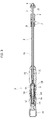
Figure 1 is a perspective view of a deployment instrument, according to embodiments of the disclosure; -
Figure 2A is an exploded perspective view of the instrument ofFigure 1 , according to embodiments of the disclosure; -
Figure 2B is an exploded view of a sub-unit of the instrument ofFigure 2A , according to pointer IIA, according to embodiments of the disclosure; -
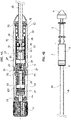
Figure 3 is a longitudinal sectional view of the instrument ofFigure 1 , according to embodiments of the disclosure; -
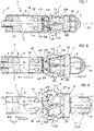
Figure 4A is a partly disassembled view of an end portion of the instrument, according to embodiments of the disclosure; -
Figure 4B is a view of an opposite end portion of the instrument, according to embodiments of the disclosure; -
Figure 5 is a perspective view corresponding toFigure 4A , according to embodiments of the disclosure. - While the disclosure is amenable to various modifications and alternative forms, specific embodiments have been shown by way of example in the drawings and are described in detail below. The intention, however, is not to limit the disclosure to the particular embodiments described. On the contrary, the disclosure is intended to cover all modifications, equivalents, and alternatives falling within the scope of the disclosure as defined by the appended claims,
-
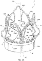
Figures 6A and6B are perspective views of a heart valve prosthesis that may be deployed by the deployment instrument of the embodiments, and -
Figures 7 to 9 are representative of an exemplary deployment sequence involving the prosthesis offigures 6A and6B . -
Reference number 1 inFigure 1 applies to a deployment instrument for expandable heart valve prostheses according to various embodiments of this disclosure. - In embodiments, such as that exemplified in the figures, the
deployment instrument 1 includes: - a
shaft 2 having a longitudinal axis X1; - a
handle 3 at a first end of theshaft 2; and - a
carrier portion 4 at a second end of theshaft 2. - The
carrier portion 4 is configured for holding an expandable heart valve prosthesis in a radially collapsed condition for delivery to the implantation site. - Referring now to
Figure 2A , in embodiments thecarrier portion 4 may include ahub 5 fixed to thehandle 3 via theshaft 2, afirst deployment element 6, and asecond deployment element 7. Each of thefirst deployment element 6 andsecond deployment element 7 is configured to hold a corresponding portion of an expandable heart valve prosthesis in a radially collapsed condition. - In embodiments, the
first deployment element 6 may be provided as a cup member featuring an ogee-like shape, preferably with a blunt end to avoid damaging to the patient's tissues and vasculature. - The
second deployment element 7 may be - instead - provided as a sheath member including aplug 8 and asheath 9 fitted onto the plug 8 (e.g. by interference fitting, or else thermally bonded thereto). - The
hub 5 is fixed to thehandle 3 via afirst shaft member 10 provided as a tubular element (preferably thin walled) that attaches at one end thereof to the hub, and at another end thereof at thehandle 3. Attachment may be provided, e.g., by snap fitting - as visible in the figures - by providing openings at the end of theshaft member 10 configured to be engaged by resilient protrusions on thehub 5 and thehandle 3 respectively. - In embodiments, the handle comprises a
drive member 11 including afirst drive feature 12 and asecond drive feature 13. Thedrive member 11 may include a knob K for operation by the practitioner, and a hollow stem ST featuring the first drive feature on an inner surface, and the second drive feature on an outer surface. - In other embodiments, depending on how the drive feature is made and operates, both drive features may be provided on one and a same surface of the stem ST, or else on concentric surfaces with different diameters.
- In some embodiments, such as that visible in the figures, the drive features 12, 13 may be provided as threaded portions of the stem AT, wherein the
drive feature 12 is an internal thread provided on an inner cylindrical surface of the stem, while thedrive feature 13 is an external thread provided on an outer cylindrical surface of the stem ST. - In some embodiments, the drive features 12, 13 may be provided as a cam track that develops on the respective surface of the stem ST (such as a drum cam). In other embodiments, depending on the needs, a mixed configuration may be adopted featuring a thread for one of the drive features 12, 13 and a cam track for the other of the drive features 12, 13. In some embodiments, any profile capable of transforming its motion (generally a rotary motion) into another motion (generally an axial motion) of another member that engages with the profile may be regarded as a drive feature within the context of the present disclosure.
- Whatever the embodiments of the drive features 12, 13 the same are arranged so that upon operation of the
drive member 11 thefirst drive feature 12 is configured to axially displace the first deployment element 6 (along the axis X1) in a first direction, and thesecond drive feature 13 is configured to axially displace thesecond deployment element 7 in a second direction, wherein the first direction and the second direction are opposite to one another. For example, when the drive features 12, 13 are provided both as threaded portions they will have opposite winding threads (i.e. a right thread and a left thread) so that a rotation of thedrive member 11 will result in a distal displacement for one of the deployment elements and a proximal displacement in the other of the deployment elements and vice versa. When the drive features 12, 13 are provided as cam tracks, they will develop on the surface(s) of the stem ST of thedrive member 11 e.g. with opposite slopes, so that - once again - a rotation of thedrive member 11 will result in a distal displacement for one of the deployment elements and a proximal displacement in the other of the deployment elements and vice versa. - In embodiments such as that depicted in the figures the
first deployment element 6 of thecarrier portion 4 is connected to a first axiallymovable element 14 via a connecting rod orshaft member 15 that is slidably arranged into theshaft member 10. As visible inFigure 2A , the rod ofshaft member 15 has an axial extension higher than the axial extension of theshaft member 10. The first axiallymovable element 14 engages thefirst drive feature 12 of the drive member 11: specifically, in these embodiments theelement 14 includes astud 16 which may be threaded (externally threaded for the embodiment in the figures) or otherwise provided with a feature capable of mating with thedrive feature 12. Thestud 12 has two diametrically opposite flat sides serving as an anti-rotation feature, making the element 14 a non-rotating, axially displacing member. - The
second deployment element 7 of thecarrier portion 4 is connected to a second axiallymovable element 17 via asecond shaft member 18 arranged around thefirst shaft member 10, and slidable relative thereto. In some embodiments, such as that depicted in the figures, thesecond shaft member 18 has the shortest axial length relative to the first shaft member and the rod orshaft member 15. The second axiallymovable element 17 engages thesecond drive feature 13 of thedrive member 11 to drive thesecond deployment element 7. - The
shaft 2 has therefore in embodiments a layered structure including thesecond shaft member 18 as outer layer, thefirst shaft member 10 as middle layer, and the rod orshaft member 15 as a core. - According to an advantageous aspect of the disclosure, the second axially
movable member 17 includes afirst portion 19 and asecond portion 20, wherein thefirst portion 19 engages thesecond drive feature 13, while thesecond portion 20 is axially movable relative to thefirst portion 19 to provide an axial displacement of thesecond deployment element 7 in the second direction independently of thedrive member 11. - More specifically, in embodiments as illustrated herein (
Figure 2B ) thefirst portion 19 may include anannular portion 19C wherefrom a first pair ofaxial extensions 21, diametrically opposite, protrude. - An
internal thread 22 is provided on the cylindrical inner surfaces of theextensions 21 and theannular member 19C, to engage the thread of thedrive feature 13. Alternatively, these surfaces may be provided with one or more cam followers in the event that thedrive feature 13 is provided as a cam track. - The
extensions 21 merge at aflange 23 wherefrom a second pair ofaxial extension 24 departs axially away from theextensions 21. Theaxial extensions 24 are set once again at diametrically opposite positions, and cover an angular range wider than that covered by theextensions 21. This allows opening a pair of throughaxial slots 25 in the cylindrical wall of each extension 24 (thegrooves 25 being diametrically opposite as well), as well as a pair ofaxial grooves 26 that separate the twoaxial extensions 24. Both theslots 25 and thegrooves 26 serve as guide features for theportion 20. - Coming to the latter, the
portion 20, similarly to theportion 19, features anannular member 27 wherefrom a third pair ofaxial extensions 28 protrude. When theportions extensions 28 will have, albeit on a larger diameter, the same angular position (diametrically opposite) as theextensions 24. Theextensions 28 are each provided with aradially protruding plug 29 which is configured to snap fit into a respective opening 30(Figures 2A, 5) provided at a proximal end of theshaft member 18, wherein proximal and distal are used herein relative to the handle 3 (proximal: towards thehandle 3; distal: away from the handle 3). - A pair of radially protruding
teeth 31, diametrically opposite, extend from an inner surface of theannular portion 27 and inwardly of the same, while a pair ofguide fingers 32, which may be partly resilient, extend axially at diametrically opposite positions at right angles from those of theteeth 31. Specifically, thefingers 32 are aligned with theslots 25, while theteeth 31 are aligned with thegrooves 26. - When assembled together, the
second portion 20 partly overlaps thefirst portion 19 at theextensions 24, and specifically theannular member 27 is slidably mounted over theextensions 24 guided by theteeth 31 through thegrooves 26, and thefingers 32 along the slots 25 (which also serve as a locking feature for theportion 20 relative to theportion 19 in the fully extended position on account of the engagement of thefingers 32 therein). - The
fingers 32 are also provided with a radially protruding end portion (such as theplugs 29 at the ends of the extensions 28) that engages theslots 25 to prevent axial separation of theportions portion 20 to be axially pulled by theportion 19 in a proximal direction. An elastic element S is fitted around theextensions 24 between theflange 23 and theannular member 27 and is configured to bias thefirst portion 19 and thesecond portion 20 away from one another, and specifically to bias thesecond portion 20 to an extended position wherein the radially protruding ends of thefingers 32 abut onto the distal ends of theslots 25. - Referring once again to
Figure 2A , and additionally toFigure 3 , thehandle 3 includes afirst shell 33 and asecond shell 34 which, in embodiments, define respectively circumferential half of the overall shell of thehandle 3. Each of theshells cradles elements - In some embodiments, the interior of the
shells first cradle 35 and asecond cradle 36, each intended to cradle a sub-set of the components previously identified in this disclosure. With reference toFigure 2A ,2B ,3 ,4A , and5 , thefirst cradle 35 receives thedrive member 11, particularly the stem ST, thefirst portion 19 of the second axiallymovable element 17 up to the end of the extensions 21 (the latter engaging the drive feature 13), and thestem 16 of the first axiallymovable member 14 that engages thedrive feature 12 at the interior of the stem ST. - The
cradle 35 is functionally separated from thecradle 36 by a pair of guide shoulders 37 which may act both as sockets for fastening screws FS that secure theshells extensions 21, which are accordingly prevented from rotating (and theportion 19 overall as well) while enabled to axially displace when thedrive member 11 is operated. Anti-rotation features for the assembly ofportions flat sides 19F of theportion 19 sliding along corresponding inner walls of thecradles 35, 36 (Figures 2A ,4A ,5 ), thus making the assembly ofportions - Similar shoulders to the guide shoulders 37 may be provided at opposite ends of the
shells drive member 11 and the axially slidable portions of theshaft 2, such as theshaft member 18. - In embodiments, the
cradle 36 in turn houses the remainder of the components of thehandle 4, and specifically it houses the remainder of theportion 19 of the second axiallymovable element 17, the remainder of the first axially movable element, as well as proximal portions of theshaft 2 including a proximal portion of the rod orshaft member 15 fitting into theelement 14, a proximal portion of theshaft member 10 fixing thehub 5 to thehandle 3, and a proximal portion of theshaft member 18 engaging theplugs 29 on theextensions 28. - As to the
shaft member 10, the same is secured to theshell 33 by way of a pair oftabs 38 extending along chordal planes parallel to one another and parallel to the axis X1, and configured to sit throughside openings 38F (Figure 2A , similar to the openings 30)to axially secure theshaft member 10 to the handle 3 (particularly to the shell 33) and thehub 5 too in the process. As to thetabs 38, in one embodiment they do not have a counterpart in theshell 34 primarily for reasons of assembly. In other embodiments thetabs 38 may be provided on theshell 34 only, while in yet other embodiments onetab 38 may be provided on theshell 33, the other on theshell 34. - Operation of the
deployment instrument 1 according to embodiments of this disclosure will now be described. - The
deployment instrument 1 is operable to delivery and release a heart valve prosthesis including a radially contractible/radially expandable armature and a prosthetic valve carried thereby to an implantation site. - For this purpose, the
deployment elements carrier portion 4 are operable from a minimum (allowed) mutual distance condition visible inFigure 3 and associated to a loading/delivery operating condition of the prosthesis, to a larger mutual distance condition visible inFigures 4B and9 , and associated to valve deployment/release at the implantation site, and yet to a maximum (allowed) mutual distance condition associated to complete valve deployment/release at the implantation site. The distance referred to is that along the axis X1. - In the minimum mutual distance condition the heart valve prosthesis features a portion, particularly an first end portion (inflow/outflow), of the armature kept radially collapsed between the
deployment element 6 and thehub 5, and another portion, particularly again an end portion (outflow/inflow) of the armature kept radially collapsed between thesheath member 9 and thehub 5. The intermediate portions of the valve armature are in various embodiments left free of radial contraction and extend over the interspace between thesheath member 9 and thedeployment element 6. - In some embodiments, going through these mutual distance conditions is performed via operation of the drive member (minimum to larger mutual distance), and via operation of the second axially
movable element 17 through the shaft member 30 (larger to maximum mutual distance). - As already anticipated, the
drive member 11 has drive features 12, 13 which are configured to determine an opposite axial motion of thedeployment elements elements deployment element 6 in a first direction being a distal direction, and an axial motion of thedeployment element 7 in a second direction being a proximal direction. By doing so, thedeployment element 6 displaces distally of theshaft 2, while thedeployment element 7 displaces proximally of theshaft 2, towards thehandle 3. This relative motion allows transitioning from the minimum mutual distance condition to the larger mutual distance condition, thereby allowing the portion of the armature kept radially collapsed by thedeployment element 6 to radially expand. - In embodiments the drive features 12, 13 do allow for reverse operation so that a counterclockwise rotation will result in the inversion of first and second directions: the first direction will become a proximal direction, while the second direction will become a distal direction, thereby reducing the mutual distance of the deployment elements along the axis X1. This may be useful primarily to load the valve prosthesis into the
carrier portion 4, as well as whenever deployment of the armature portion associated to thedeployment element 6 is not completed yet and is deemed unsatisfactory for the progress reached thus far. As far as the proximal axial displacement of thedeployment element 7, the same occurs with theelement 17 in the fully extended position, in so far as the elastic element S biases theportion 20 in abutment at the end of theslots 25, thereby enabling pulling of theportion 20 in a proximal direction by theportion 19, which instead is directly displaced by thedrive feature 13. - The
drive feature 12 on its hand axially displaces theelement 14, which through the rod/shaft member 15 transfers motion to thedeployment element 6. - By proceeding further with clockwise rotation, the larger mutual distance condition may be reached whereat, either the
flange 23 comes into contact with theshoulders 37 as visible inFigure 4A , or the mutual distance achieved is deemed enough by the practitioner to proceed further with a fast release of the prosthesis. - In the first case (end of travel being reached), the portion 19 - and the
deployment element 7 including thesheath member 9 accordingly - are not allowed to displace any more proximally under the action of thedrive member 11. In this condition, however, a certain degree of overlap remains between thesheath member 9 and the hub 5 (seeFigure 4B ), so that full release of the prosthesis at the implantation site may not be attained. On the other hand, this condition generally corresponds to a stage of the implantation procedure wherein the prosthesis may be considered already optimally positioned at the implantation site, so that the remainder of the deployment calls for a conclusion as quickly as possible. - In the second case (end of travel not reached, but prosthesis ready for final release), once again a certain degree of overlap remains between the
sheath member 9 and the hub 5 (seeFigure 4B ), but full release of the prosthesis at the implantation site may be attained anyway by the action of thesole drive member 11. That is, if the practitioner were to change his/her mind and proceed with final release using the sole drive member, that option is still available. - In either case, this is where the arrangement of the axially
movable element 17 may come into play. - The
portion 20 has an extra share of axial displacement provided by the sliding coupling between theportions portion 20 relative to theportion 19 which results in an equal proximal motion of thesheath member 9 to the condition of maximum mutual distance allowed by the design of theinstrument 1, or anyway to a condition of mutual distance determined by the sum of the distance travelled by virtue of thedrive member 11, and the extra share of axial displacement allowed by theportion 20 relative to theportion 19. - The additional travel may be covered by gripping the
shaft member 18 and pulling the same proximally towards thehandle 3. This may be done, for example, by holding thehandle 3 in one hand, and pulling theshaft member 18 back (proximally) with the other hand. This will very rapidly retract thesheath member 9 from thehub 5 removing the remaining overlap and fully releasing the valve. The extent of the axial travel that can be covered this way may depend on the length of theslots 25 and/or the solid length of the elastic element S, and/or the axial distance at rest (i.e. in the fully extended condition of the element 17) between the overlappingportions - The coverage of this extra axial travel by the
deployment element 7 occurs independently of thedrive member 11, as the same is not configured to control this particular relative sliding of theportions drive member 11 cannot anyway control any further movement of the deployment elements once the condition ofFigure 4A has been reached. - As far as the second case, which may generally be a preferred option, it is worth noting that the extra axial travel from the relative motion between the
portions portion 19 through thehandle 3 may be preferably sized and dimensioned so as to allow a full deployment of the prosthesis solely by the action of thedrive member 11, in order not to call for a mandatory action on themovable element 17 to terminate the release of the prosthesis, while leaving the design of theinstrument 1 open to the possibility of a fast (final) release at the discretion of the practitioner. If the practitioner wants so, then resort to the extra travel feature may be made. If the practitioner is more familiar/comfortable with a release provided by manipulation of a single drive member - such as the drive member 11 - the option is available to complete the release with the sole action of the drive member. - It follows, more in general, that the first case is actually a sub-species of the second case wherein the extra axial travel of the
deployment element 7 independently of thedrive member 11 is called into action at the end of the axial travel made available by the design of thedrive feature 13 and/or thesecond portion 19 engaging thedrive feature 13. -
Figures 7 to 9 illustrate an exemplary deployment sequence applicable to a heart valve prosthesis P shown infigures 6A ,6B . - With reference to
figures 6A and6B , the heart valve prosthesis P includes anarmature 102 for anchorage of the valve prosthesis at an implantation site. Thearmature 102 defines a lumen for the passage of the blood flow and has a longitudinal axis X2. - The prosthesis P also includes a set of
prosthetic valve leaflets 104 supported by thearmature 102 and configured to move, under the action of blood flow ( which has a main flow direction roughly corresponding to that of the axis X1): - in a radially divaricated condition to enable the flow of blood through the lumen in a first direction, and
- in a radially contracted condition, in which the
valve leaflets 104 co-operate with one another and block the flow of blood through theprosthesis 1 in the direction opposite the first direction. This is commonly referred to as leaflet coaptation. - The
prosthetic leaflets 104 may be in any number compatible with operation as replacement heart valve. In one embodiment, the set includes a pair of leaflets. In another embodiment, such as that shown in the figures, the set includes three prosthetic valve leaflets 104 (e.g. for an aortic valve prosthesis). In yet another embodiment, the set may include fourleaflets 104. - The
armature 102 includes anannular part 106, and a pattern ofarched struts 108 carried by theannular part 106. Theannular part 106 has a structure which can expand from a radially contracted condition, associated to delivery of the prosthesis to implantation site, to a radially expanded condition wherein the prosthesis is withheld at the implantation site. In these embodiments, the annular part may have a mesh structure including an annular pattern of multiple strut clusters (cells) having polygonal shape (hexagonal, rhomboidal, etc.). - In various embodiments, the annular part is covered by a cuff such as the sealing cuff SC to provide sealing at the implantation site, the cuff being arranged outside of the lumen of the
armature 102. Advantageously, the cuff may be sewn or stitched to theannular part 106. Theannular part 106 with the sewing cuff attached thereto provides an inflow portion of the heart valve prosthesis P. - As said, depending on the technique used to manufacture the valvular sleeve, wherein the cuff SC may be integral with the set of
prosthetic valve leaflets 104. - The pattern of
arched struts 108 includes proximal ends 110 connected to theannular part 106, anddistal ends 112 spaced axially from the proximal ends 110 and arranged at an end of thearmature 102 opposite theannular part 106. In various embodiments, the distal ends 112 coincide with distal ends of thearmature 102, and in embodiments where the distal end of thearmature 102 coincides with a distal end of the prosthesis 100 as a whole, the distal ends 112 coincide with a distal end of the prosthesis as well. - The
armature 102 further includes: - a plurality of
sets 114 of anchoringformations 116 configured to protrude radially outwardly of theannular part 106, each set 114 being supported by at least one of theannular part 106 and a correspondingarched strut 108, and - a plurality of support posts 118, each supported by adjacent
arched struts 108, wherein thesets 114 of anchoringformations 116 alternate with the support posts 118 around the longitudinal axis X1. In various embodiments the support posts 118 are cantilevered to adjacentarched struts 108 and are configured as fixing locations for the prosthetic valve, specifically for the pleat formations PF at the commissural points of the valve. - Each
arched strut 108 extends from a firstproximal end 110, to adistal end 112, then to a secondproximal end 110 in a valley-peak-valley sequence, wherein valleys are located at the proximal ends 110, and peaks are located at the distal ends 112. In various embodiments the pattern of arched struts includes three adjacent and preferably identical arched struts 108 (such as in the figures). - The pattern of
arched struts 108 includesdistal portions 120 located at the distal ends 112, andinter-strut portions 122 located at the proximal ends 110. Thedistal portions 120 may be shaped so as to provide a marked local variation in the shape of the strut, for example by exhibiting a C-shape as shown in the figure. Thedistal portions 120 may provide coupling locations for other devices such as a valve holder or a hub of a carrier portion of a delivery catheter. In other embodiments, thedistal portions 120 may be provided as closed-loop structures such as eyes or eyelets. The pattern ofarched struts 108, and particularly the distal ends with thedistal portion 120 thereof provide an outflow portion of the prosthesis P. - In various embodiments, the
inter-strut portions 122 are essentially V-shaped and are defined by the roots of the adjacent arched struts departing from the sameproximal end 110. In certain embodiments, theinter strut portions 122 may exhibit a Y-shape such as, for instance, that shown in the figure wherein eachinter-strut portion 122 extends through the mesh of theannular part 106. Alternatively, they may exhibit a U-shape. In these embodiments, the mesh of theannular part 106 is provided as a sequence of rhomboidal strut clusters (cells) sequentially connected to each other at endpoints of a diagonal line (typically the shortest diagonal) and exhibiting accordingly an identical circular pattern of free ends on opposite sides of a circumference extending through the sequence of the connection points. The Y-shapedinter-strut portion 122 is thus integrally formed at a selected connection point between two adjacent rhomboidal strut clusters, and typically extends no further than the proximal end of thearmature 102. - The support posts 118 are angularly arranged at an inter-strut location, i.e. a circumferential location arranged at an area where an inter-strut portion 122 (as well as - accordingly - a
proximal end 110 shared by two adjacent arched struts 108) is provided. The support posts may be advantageously provided as cantilevered to both the adjacentarched struts 8 intervening at aninter-strut portion 122 via a first and a second cantilever struts 124, 126, each connected to a corresponding one of said adjacentarched struts 8 as shown in the figures. The cantilever struts 124, 126 merge into eachcorresponding post 118 starting from locations on respectivearched strut 108 approximately halfway through the portion of thearched strut 108 extending from aproximal end 110 to adistal end 112. The connection points at which the Y-shapedinter-strut portion 122 is formed may be chosen so that the same portions are evenly spaced (angular-wise) around the axis X1. The same applies to the support posts 118, which may be arranged so as to be evenly spaced (angular-wise) around the axis X1. - In the embodiment shown in the figure, the
armature 102 comprises threearched struts 108, threeposts 118 spaced 120° around the axis X1, and threesets 114, so that the sequence around the axis X1 is post 118 - set 114 - post 118 - set 114 - post 118 - set 114 (in this sense, even thestruts 108 and thesets 114 do follow a 120degree-like distribution). In this embodiment the threesets 114 include each a pair of anchoringformations 116, wherein each set 114 (and accordingly each anchoring formation 116) extends bridge-wise between theannular part 106 and the correspondingarched strut 108. - With reference to
figure 7 , the prosthesis P is loaded into thedeployment instrument 1 so that the annular part 106 (and the sealing cuff thereon) is held in a radially contracted condition by thefirst deployment element 6, while thedistal portions 120 at distal ends of thearched struts 108 are held in a radially contracted condition by the second deployment element 7 (sheath 9 thereof). Thesheath 9 may be guided during deployment byspoke members 5A protruding radially from thehub 5, wherein thespoke members 5A provide radial support to thesheath 9. Furthermore, in embodiments, thedistal portions 120 engage to atoothed ring member 5B that likewise protrudes radially from thehub 5. Engagement of thetoothed ring member 5B may occur so that thedistal portions 120 sit astride of a respective tooth of thetoothed ring 5B as visible infigures 7 to 9 , wherein each respective tooth on its hand protrudes into thedistal portion 120. This prevents i.a. unwanted axial displacement of the prosthesis, as well as unwanted rotation of the prosthesis around the axis X1 during deployment. - The
spoke members 5A and thetoothed ring member 5B may be provided integral with the hub 5 (onetoothed ring 5B and threespokes 5A - The anchoring
formations 116 are left radially unconstrained as in embodiments there is no deployment element that extends axially over the anchoringformations 116 to radially constrain the same. Accordingly, all of the elements located in the same axial region as the anchoringformations 116 are arranged with no radial constraint (this includes, i.a., theposts 118 as well as the pleat formations PF) . - With reference to
figure 8 , operation of thedrive member 12 results in an increase in mutual distance between thedeployment elements deployment element 6. The motion directions of each of thedeployment elements deployment element 7 is controlled by drivingmember 12,second driving feature 13, and second axially movable element 17 (portions deployment element 6 is controlled, on its hand, by drivingmember 12 and first axiallymovable element 14. As may be seen in the figure, in embodiments an outflow portion OF of the prosthesis P is still substantially held radially contracted by thesheath 9, wherein the outflow portion OF includes i.a. thedistal portions 120 of thearched struts 108. - Then,
figure 9 , full deployment of the prosthesis P is shown, wherein both thesheath 9 and thedeployment element 6 are clear of the prosthesis P. This eventually releases the outflow portion OF and achieves full deployment of the prosthesis P. The exemplary condition shown infigure 9 may be reached, as per the above, either: - by operating the driving
member 12 to cover all of the available travel(s) for thedeployment elements figure 9 once again involvingelements deployment element 7, combined with composite reference on the lower rightcorner involving elements deployment element 6. This corresponds to the condition depicted in solid lines infigure 9 ; or - by operating the driving
member 12 to cover a desired share of the axial travel available for the deployment element 7 (thedeployment element 6 at that point will have already released the inflow portion IF), then covering the extra axial travel by means of backward (proximal) displacement of theportion 20 relative to theportion 19, as represented by the composite reference in the lower leftcorner involving elements elements 19, 20 (fast proximal/backwards motion). In this latter case, the position of thedeployment member 6 is shown in phantom line (while the ending position of thesheath 9 is the same as above), as the same does not cover all of the available axial travel.The person skilled in the art will thus appreciate that in embodiments disclosed herein thedeployment instrument 1 allows for a variable control pattern matching the needs of specific stages of the valve deployment procedure. Through all of the stages wherein thedeployment elements drive member 8 and the drive features 12, 13 provide the desired displacement rate. Note that the displacement rate may in principle be either equal or different between the two drive features. For example, in some embodiments both drive features may provide for an equal axial displacement - subject to the opposite directions condition above - of thedeployment elements movable elements - When - instead - a fast displacement is required to quickly bring the valve release to an end, the features of the axially
movable member 17 come into play allowing for an extra travel that can be controlled independently of thedrive member 11, and ultimately in a different way, particularly one that supports such a fast motion.
Claims (15)
- A deployment instrument (1) for expandable heart valve prostheses including:a shaft (2) having a longitudinal axis (X1);a handle (3) at a first end of the shaft (2); anda carrier portion (4) at a second end of the shaft (2), the carrier portion (4) configured for holding an expandable heart valve prosthesis in a radially collapsed condition for delivery to the implantation site,wherein:the carrier portion (4) includes a hub (5) fixed to the handle (3) via the shaft (2), a first deployment element (6) and a second deployment element (7), each of said first deployment element (6) and second deployment element (7) configured to hold a corresponding portion of an expandable heart valve prosthesis in a radially collapsed condition,the handle (3) comprises a drive member (11) including a first drive feature (12) and a second drive feature (13),the first deployment element (6) of the carrier portion (4) is connected to a first axially movable element (14), the first axially movable element (14) engaging (16) said first drive feature of the drive member (11),the second deployment element (7) of the carrier portion (4) is connected to a second axially movable element (17), the second axially movable element (17) engaging said second drive feature (13) of the drive member (11), wherein upon operation of the drive member (11) the first drive feature (12) is configured to axially displace the first deployment element (14) in a first direction, and the second drive feature (13) is configured to axially displace the second deployment element (17) in a second direction, said first direction and said second direction being opposite to one another, andfurther wherein the second axially movable member (17) includes a first portion (19) and a second portion (20), the first portion (19) engaging the second drive feature (13), and the second portion (20) being axially movable relative to the first portion (19) to provide an axial displacement of the second deployment element (7) in the second direction independently of the drive member (11).
- The deployment instrument (1) of Claim 1, wherein the first end of the shaft (2) is a proximal end, and the second end of the shaft (2) is a distal end.
- The deployment instrument (1) of Claim 1 or 2, wherein the first direction is a distal direction, and the second direction is a proximal direction.
- The deployment instrument (1) of Claim 1, wherein said first drive feature (12) comprises a first threaded portion, and said second drive feature (13) comprises a second threaded portion.
- The deployment instrument of Claim 4, wherein said drive member (11) is a rotary drive member comprising a knob (K) and a stem (ST), the first drive feature (12) being provided on a first surface of the stem (ST), and the second drive feature (13) being provided on a second surface of the stem (ST).
- The deployment instrument of Claim 5, wherein said stem (ST) is a hollow member, said first drive feature being provided on an inner surface of the stem (ST), and said second drive feature being provided on an outer surface of the stem (ST).
- The deployment instrument of Claim 1, wherein the first portion (19) and the second portion (20) of the second axially movable element (17) are partly overlapping and slidably coupled to one another.
- The deployment instrument (1) of Claim 7, the second axially movable element including an elastic element (S) biasing the second portion (20) away from the first portion (19).
- The deployment instrument (1) of any of claims 1 and 7-8, wherein the first portion includes:an annular portion (19C) wherefrom a first pair of diametrically opposite axial extensions (21) protrude; andan internal thread (22) provided on the cylindrical inner surfaces of the axial extensions (21) of the first pair and the annular member (19C), the internal thread being configured to engage the second drive feature (13),wherein the axial extensions (21) merge at a flange (23) wherefrom a second pair of diametrically opposite axial extensions (24) departs axially away from the first pair of axial extensions (21).
- The deployment instrument (1) of Claim 9, wherein the axial extensions (24) of the second pair are arranged at a location at right angle relative to the axial extensions (21) of the first pair.
- The deployment instrument of Claim 9 or 10, wherein each axial extension of the second pair includes a through axial slot (25), the axial extensions (24) of the second pair being separated by a pair of axial grooves (26).
- The deployment instrument of any of Claim 9 to 11, wherein the second portion (20) of the second axially movable element (17) includes an annular member (27) wherefrom a third pair of diametrically opposite axial extensions (28) protrude.
- The deployment instrument of Claim 12, wherein the axial extensions (28) of the third pair have the same position as the axial extensions (24) in the second pair, and are each provided with a radially protruding plug (29),wherein a pair of radially protruding teeth (31), diametrically opposite, extend from an inner surface of the annular portion (27) and inwardly of the same, while a pair diametrically opposite guide fingers (32) extend axially at said annular portion (27) at positions at right angles relative to those of the radially protruding teeth (31), andwherein the guide fingers (32) are aligned with a corresponding through axial slot (25) and slidably engage the same, while the teeth (31) are aligned with the grooves (26) separating the axial extensions (24) of the second pair, and are slidable therethrough.
- The deployment instrument of any of the previous claims, wherein the shaft (2) has a layered structure and includes:a first shaft member (10) as middle layer;a second shaft member (18) as outer layer; anda rod or shaft member (15) as a core,whereinthe first shaft member connects the hub (5) of the carrier portion to the handle (3),the second shaft member (18) connects the second deployment element (7) to the second axially movable element (17, 20),the rod or shaft member (15) connects the first deployment element (6) to the first axially movable member (14).
- The deployment instrument of Claim 14, wherein the second shaft member (18) is engaged by the axial extensions (28) of the third pair.
Applications Claiming Priority (1)
| Application Number | Priority Date | Filing Date | Title |
|---|---|---|---|
| PCT/IB2018/053646 WO2019224581A1 (en) | 2018-05-23 | 2018-05-23 | A device for the in-situ delivery of heart valve prostheses |
Publications (2)
| Publication Number | Publication Date |
|---|---|
| EP3796872A1 EP3796872A1 (en) | 2021-03-31 |
| EP3796872B1 true EP3796872B1 (en) | 2022-07-20 |
Family
ID=62683379
Family Applications (1)
| Application Number | Title | Priority Date | Filing Date |
|---|---|---|---|
| EP18732478.5A Active EP3796872B1 (en) | 2018-05-23 | 2018-05-23 | A device for the in-situ delivery of heart valve prostheses |
Country Status (7)
| Country | Link |
|---|---|
| US (1) | US12318289B2 (en) |
| EP (1) | EP3796872B1 (en) |
| JP (1) | JP7074930B2 (en) |
| CN (1) | CN112384174B (en) |
| AU (1) | AU2018424863B2 (en) |
| CA (1) | CA3101099A1 (en) |
| WO (1) | WO2019224581A1 (en) |
Cited By (14)
| Publication number | Priority date | Publication date | Assignee | Title |
|---|---|---|---|---|
| US11602429B2 (en) | 2019-04-01 | 2023-03-14 | Neovasc Tiara Inc. | Controllably deployable prosthetic valve |
| US11617650B2 (en) | 2012-05-30 | 2023-04-04 | Neovasc Tiara Inc. | Methods and apparatus for loading a prosthesis onto a delivery system |
| US11737872B2 (en) | 2018-11-08 | 2023-08-29 | Neovasc Tiara Inc. | Ventricular deployment of a transcatheter mitral valve prosthesis |
| US11779742B2 (en) | 2019-05-20 | 2023-10-10 | Neovasc Tiara Inc. | Introducer with hemostasis mechanism |
| US11793640B2 (en) | 2017-08-25 | 2023-10-24 | Neovasc Tiara Inc. | Sequentially deployed transcatheter mitral valve prosthesis |
| US11931254B2 (en) | 2019-06-20 | 2024-03-19 | Neovasc Tiara Inc. | Low profile prosthetic mitral valve |
| US11998447B2 (en) | 2019-03-08 | 2024-06-04 | Neovasc Tiara Inc. | Retrievable prosthesis delivery system |
| US12036117B2 (en) | 2019-04-10 | 2024-07-16 | Neovasc Tiara Inc. | Prosthetic valve with natural blood flow |
| US12053369B2 (en) | 2011-11-23 | 2024-08-06 | Neovasc Tiara Inc. | Sequentially deployed transcatheter mitral valve prosthesis |
| US12109111B2 (en) | 2015-12-15 | 2024-10-08 | Neovasc Tiara Inc. | Transseptal delivery system |
| US12138159B2 (en) | 2012-02-14 | 2024-11-12 | Neovasc Tiara Inc. | Methods and apparatus for engaging a valve prosthesis with tissue |
| US12193932B2 (en) | 2016-01-29 | 2025-01-14 | Neovasc Tiara Inc. | Prosthetic valve for avoiding obstruction of outflow |
| US12201524B2 (en) | 2016-11-21 | 2025-01-21 | Neovasc Tiara Inc. | Methods and systems for rapid retraction of a transcatheter heart valve delivery system |
| US12611303B2 (en) | 2010-05-05 | 2026-04-28 | Neovasc Tiara Inc. | Transcatheter mitral valve prosthesis |
Families Citing this family (3)
| Publication number | Priority date | Publication date | Assignee | Title |
|---|---|---|---|---|
| WO2019224577A1 (en) | 2018-05-23 | 2019-11-28 | Sorin Group Italia S.R.L. | A cardiac valve prosthesis |
| WO2023007228A1 (en) | 2021-07-29 | 2023-02-02 | Corcym S.R.L. | Systems and methods for collapsing and loading a prosthetic device |
| EP4391972A4 (en) * | 2021-12-17 | 2025-09-10 | Meril Life Sciences Pvt Ltd | Conical Expansion Mitral Valve Repair Device |
Citations (4)
| Publication number | Priority date | Publication date | Assignee | Title |
|---|---|---|---|---|
| EP1935377B1 (en) * | 2006-12-19 | 2010-03-24 | Sorin Biomedica Cardio S.R.L. | Instrument for in situ deployment of cardiac valve prostheses |
| US20130231735A1 (en) * | 2012-03-01 | 2013-09-05 | Foundry Newco Xii, Inc. | Hydraulic delivery systems for prosthetic heart valve devices and associated methods |
| US20130297011A1 (en) * | 2011-08-18 | 2013-11-07 | St. Jude Medical, Cardiology Division, Inc. | Devices and methods for transcatheter heart valve delivery |
| US20140067050A1 (en) * | 2012-09-05 | 2014-03-06 | Medtronic Vascula Galway Limited | Trans-Aortic Delivery System With Containment Capsule Centering Device |
Family Cites Families (986)
| Publication number | Priority date | Publication date | Assignee | Title |
|---|---|---|---|---|
| US3143742A (en) | 1963-03-19 | 1964-08-11 | Surgitool Inc | Prosthetic sutureless heart valve |
| US3334629A (en) | 1964-11-09 | 1967-08-08 | Bertram D Cohn | Occlusive device for inferior vena cava |
| US3363442A (en) | 1965-05-25 | 1968-01-16 | North American Aviation Inc | Tube tapering device |
| GB1127325A (en) | 1965-08-23 | 1968-09-18 | Henry Berry | Improved instrument for inserting artificial heart valves |
| GB1172990A (en) | 1965-12-11 | 1969-12-03 | Valery Ivanovich Shumakov | Cardiac Valve Prosthesis and Instrument for Mounting and Fixing it in Position |
| US3587115A (en) | 1966-05-04 | 1971-06-28 | Donald P Shiley | Prosthetic sutureless heart valves and implant tools therefor |
| US3514131A (en) | 1967-05-22 | 1970-05-26 | Hamilton Co | Luer lock |
| US3540431A (en) | 1968-04-04 | 1970-11-17 | Kazi Mobin Uddin | Collapsible filter for fluid flowing in closed passageway |
| GB1268484A (en) | 1968-06-28 | 1972-03-29 | Brian John Bellhouse | Improvements relating to non-return valves particularly as prosthetics |
| US3574865A (en) | 1968-08-08 | 1971-04-13 | Michigan Instr Inc | Prosthetic sutureless heart valve |
| US3671979A (en) | 1969-09-23 | 1972-06-27 | Univ Utah | Catheter mounted artificial heart valve for implanting in close proximity to a defective natural heart valve |
| US3628535A (en) | 1969-11-12 | 1971-12-21 | Nibot Corp | Surgical instrument for implanting a prosthetic heart valve or the like |
| US3642004A (en) | 1970-01-05 | 1972-02-15 | Life Support Equipment Corp | Urethral valve |
| US3657744A (en) | 1970-05-08 | 1972-04-25 | Univ Minnesota | Method for fixing prosthetic implants in a living body |
| US3755823A (en) | 1971-04-23 | 1973-09-04 | Hancock Laboratories Inc | Flexible stent for heart valve |
| US3744060A (en) | 1971-06-10 | 1973-07-10 | F Bellhouse | Prosthetic cardiac valve |
| US3868956A (en) | 1972-06-05 | 1975-03-04 | Ralph J Alfidi | Vessel implantable appliance and method of implanting it |
| US3839741A (en) | 1972-11-17 | 1974-10-08 | J Haller | Heart valve and retaining means therefor |
| US3795246A (en) | 1973-01-26 | 1974-03-05 | Bard Inc C R | Venocclusion device |
| US3874388A (en) | 1973-02-12 | 1975-04-01 | Ochsner Med Found Alton | Shunt defect closure system |
| US4291420A (en) | 1973-11-09 | 1981-09-29 | Medac Gesellschaft Fur Klinische Spezialpraparate Mbh | Artificial heart valve |
| US3997923A (en) | 1975-04-28 | 1976-12-21 | St. Jude Medical, Inc. | Heart valve prosthesis and suturing assembly and method of implanting a heart valve prosthesis in a heart |
| US4011947A (en) | 1975-05-22 | 1977-03-15 | Philip Nicholas Sawyer | Packaged prosthetic device |
| US4035849A (en) | 1975-11-17 | 1977-07-19 | William W. Angell | Heart valve stent and process for preparing a stented heart valve prosthesis |
| CA1069652A (en) | 1976-01-09 | 1980-01-15 | Alain F. Carpentier | Supported bioprosthetic heart valve with compliant orifice ring |
| US4056854A (en) | 1976-09-28 | 1977-11-08 | The United States Of America As Represented By The Department Of Health, Education And Welfare | Aortic heart valve catheter |
| US4086665A (en) | 1976-12-16 | 1978-05-02 | Thermo Electron Corporation | Artificial blood conduit |
| US4297749A (en) | 1977-04-25 | 1981-11-03 | Albany International Corp. | Heart valve prosthesis |
| GB2083362B (en) | 1977-12-29 | 1982-11-24 | Yeshiva University Albert Eins | Disposable heart valve unit |
| US4233690A (en) | 1978-05-19 | 1980-11-18 | Carbomedics, Inc. | Prosthetic device couplings |
| US4220151A (en) | 1978-09-20 | 1980-09-02 | Sherwood Medical Industries Inc. | Disposable Luer lock syringe |
| US4265694A (en) | 1978-12-14 | 1981-05-05 | The United States Of America As Represented By The Department Of Health, Education And Welfare | Method of making unitized three leaflet heart valve |
| US4222126A (en) | 1978-12-14 | 1980-09-16 | The United States Of America As Represented By The Secretary Of The Department Of Health, Education & Welfare | Unitized three leaflet heart valve |
| US4574803A (en) | 1979-01-19 | 1986-03-11 | Karl Storz | Tissue cutter |
| GB2056023B (en) | 1979-08-06 | 1983-08-10 | Ross D N Bodnar E | Stent for a cardiac valve |
| US4339831A (en) | 1981-03-27 | 1982-07-20 | Medtronic, Inc. | Dynamic annulus heart valve and reconstruction ring |
| US4470157A (en) | 1981-04-27 | 1984-09-11 | Love Jack W | Tricuspid prosthetic tissue heart valve |
| US4345340A (en) | 1981-05-07 | 1982-08-24 | Vascor, Inc. | Stent for mitral/tricuspid heart valve |
| US4501030A (en) | 1981-08-17 | 1985-02-26 | American Hospital Supply Corporation | Method of leaflet attachment for prosthetic heart valves |
| US4425908A (en) | 1981-10-22 | 1984-01-17 | Beth Israel Hospital | Blood clot filter |
| US4451936A (en) | 1981-12-21 | 1984-06-05 | American Hospital Supply Corporation | Supra-annular aortic valve |
| FR2523810B1 (en) | 1982-03-23 | 1988-11-25 | Carpentier Alain | ORGANIC GRAFT FABRIC AND PROCESS FOR ITS PREPARATION |
| SE445884B (en) | 1982-04-30 | 1986-07-28 | Medinvent Sa | DEVICE FOR IMPLANTATION OF A RODFORM PROTECTION |
| US4473077A (en) | 1982-05-28 | 1984-09-25 | United States Surgical Corporation | Surgical stapler apparatus with flexible shaft |
| US4477930A (en) | 1982-09-28 | 1984-10-23 | Mitral Medical International, Inc. | Natural tissue heat valve and method of making same |
| US4506394A (en) | 1983-01-13 | 1985-03-26 | Molrose Management, Ltd. | Cardiac valve prosthesis holder |
| US4834755A (en) | 1983-04-04 | 1989-05-30 | Pfizer Hospital Products Group, Inc. | Triaxially-braided fabric prosthesis |
| US4610688A (en) | 1983-04-04 | 1986-09-09 | Pfizer Hospital Products Group, Inc. | Triaxially-braided fabric prosthesis |
| US4722725A (en) | 1983-04-12 | 1988-02-02 | Interface Biomedical Laboratories, Inc. | Methods for preventing the introduction of air or fluid into the body of a patient |
| US4684364A (en) | 1983-04-12 | 1987-08-04 | Interface Biomedical Laboratories Corporation | Safety arrangement for preventing air embolism during intravenous procedures |
| US4612011A (en) | 1983-07-22 | 1986-09-16 | Hans Kautzky | Central occluder semi-biological heart valve |
| IT1159433B (en) | 1983-07-25 | 1987-02-25 | Sorin Biomedica Spa | PROCEDURE AND EQUIPMENT FOR THE MANUFACTURE OF VALVE FLAPS FOR CARDIAC VALVE PROSTHESIS AND CARDIAC VALVE PROSTHESIS PROVIDED WITH SUCH FLAPS |
| US4665906A (en) | 1983-10-14 | 1987-05-19 | Raychem Corporation | Medical devices incorporating sim alloy elements |
| US5387247A (en) | 1983-10-25 | 1995-02-07 | Sorin Biomedia S.P.A. | Prosthetic device having a biocompatible carbon film thereon and a method of and apparatus for forming such device |
| US4681908A (en) | 1983-11-09 | 1987-07-21 | Dow Corning Corporation | Hard organopolysiloxane release coating |
| US4787899A (en) | 1983-12-09 | 1988-11-29 | Lazarus Harrison M | Intraluminal graft device, system and method |
| US5693083A (en) | 1983-12-09 | 1997-12-02 | Endovascular Technologies, Inc. | Thoracic graft and delivery catheter |
| US4627436A (en) | 1984-03-01 | 1986-12-09 | Innoventions Biomedical Inc. | Angioplasty catheter and method for use thereof |
| US4592340A (en) | 1984-05-02 | 1986-06-03 | Boyles Paul W | Artificial catheter means |
| US4883458A (en) | 1987-02-24 | 1989-11-28 | Surgical Systems & Instruments, Inc. | Atherectomy system and method of using the same |
| US4979939A (en) | 1984-05-14 | 1990-12-25 | Surgical Systems & Instruments, Inc. | Atherectomy system with a guide wire |
| US5007896A (en) | 1988-12-19 | 1991-04-16 | Surgical Systems & Instruments, Inc. | Rotary-catheter for atherectomy |
| DE3426300A1 (en) | 1984-07-17 | 1986-01-30 | Doguhan Dr.med. 6000 Frankfurt Baykut | TWO-WAY VALVE AND ITS USE AS A HEART VALVE PROSTHESIS |
| US4580568A (en) | 1984-10-01 | 1986-04-08 | Cook, Incorporated | Percutaneous endovascular stent and method for insertion thereof |
| US5232445A (en) | 1984-11-23 | 1993-08-03 | Tassilo Bonzel | Dilatation catheter |
| SU1271508A1 (en) | 1984-11-29 | 1986-11-23 | Горьковский государственный медицинский институт им.С.М.Кирова | Artificial heart valve |
| US4601706A (en) | 1984-12-03 | 1986-07-22 | Rene Aillon | Central venous pressure catheter for preventing air embolism and method of making |
| IT1186142B (en) | 1984-12-05 | 1987-11-18 | Medinvent Sa | TRANSLUMINAL IMPLANTATION DEVICE |
| DE3530262A1 (en) | 1985-08-22 | 1987-02-26 | Siemens Ag | CIRCUIT ARRANGEMENT FOR TESTING A PASSIVE BUS NETWORK SYSTEM (CSMA / CD ACCESS METHOD) |
| US4662885A (en) | 1985-09-03 | 1987-05-05 | Becton, Dickinson And Company | Percutaneously deliverable intravascular filter prosthesis |
| US5042161A (en) | 1985-10-07 | 1991-08-27 | Joseph Hodge | Intravascular sizing method and apparatus |
| GB2181057B (en) | 1985-10-23 | 1989-09-27 | Blagoveshchensk G Med Inst | Prosthetic valve holder |
| US4733665C2 (en) | 1985-11-07 | 2002-01-29 | Expandable Grafts Partnership | Expandable intraluminal graft and method and apparatus for implanting an expandable intraluminal graft |
| US5084151A (en) | 1985-11-26 | 1992-01-28 | Sorin Biomedica S.P.A. | Method and apparatus for forming prosthetic device having a biocompatible carbon film thereon |
| DE3640745A1 (en) | 1985-11-30 | 1987-06-04 | Ernst Peter Prof Dr M Strecker | Catheter for producing or extending connections to or between body cavities |
| US4710192A (en) | 1985-12-30 | 1987-12-01 | Liotta Domingo S | Diaphragm and method for occlusion of the descending thoracic aorta |
| US4784644A (en) | 1986-01-13 | 1988-11-15 | Interface Biomedical Laboratories Corp. | Valve, catheter and method for preventing the introduction of air into the body of a patient |
| CH672247A5 (en) | 1986-03-06 | 1989-11-15 | Mo Vysshee Tekhnicheskoe Uchil | |
| US4878906A (en) | 1986-03-25 | 1989-11-07 | Servetus Partnership | Endoprosthesis for repairing a damaged vessel |
| US5061273A (en) | 1989-06-01 | 1991-10-29 | Yock Paul G | Angioplasty apparatus facilitating rapid exchanges |
| US4777951A (en) | 1986-09-19 | 1988-10-18 | Mansfield Scientific, Inc. | Procedure and catheter instrument for treating patients for aortic stenosis |
| US5133845A (en) | 1986-12-12 | 1992-07-28 | Sorin Biomedica, S.P.A. | Method for making prosthesis of polymeric material coated with biocompatible carbon |
| IT1196836B (en) | 1986-12-12 | 1988-11-25 | Sorin Biomedica Spa | Polymeric or metal alloy prosthesis with biocompatible carbon coating |
| US4748982A (en) | 1987-01-06 | 1988-06-07 | Advanced Cardiovascular Systems, Inc. | Reinforced balloon dilatation catheter with slitted exchange sleeve and method |
| IT1210722B (en) | 1987-05-11 | 1989-09-20 | Sorin Biomedica Spa | DEVICES FOR THE CONDITIONING OF BLOOD FLOWS |
| US4878495A (en) | 1987-05-15 | 1989-11-07 | Joseph Grayzel | Valvuloplasty device with satellite expansion means |
| US4872874A (en) | 1987-05-29 | 1989-10-10 | Taheri Syde A | Method and apparatus for transarterial aortic graft insertion and implantation |
| US4796629A (en) | 1987-06-03 | 1989-01-10 | Joseph Grayzel | Stiffened dilation balloon catheter device |
| US4819751A (en) | 1987-10-16 | 1989-04-11 | Baxter Travenol Laboratories, Inc. | Valvuloplasty catheter and method |
| US5133732A (en) | 1987-10-19 | 1992-07-28 | Medtronic, Inc. | Intravascular stent |
| US4909252A (en) | 1988-05-26 | 1990-03-20 | The Regents Of The Univ. Of California | Perfusion balloon catheter |
| US5032128A (en) | 1988-07-07 | 1991-07-16 | Medtronic, Inc. | Heart valve prosthesis |
| US4917102A (en) | 1988-09-14 | 1990-04-17 | Advanced Cardiovascular Systems, Inc. | Guidewire assembly with steerable adjustable tip |
| US4856516A (en) | 1989-01-09 | 1989-08-15 | Cordis Corporation | Endovascular stent apparatus and method |
| US4966604A (en) | 1989-01-23 | 1990-10-30 | Interventional Technologies Inc. | Expandable atherectomy cutter with flexibly bowed blades |
| US5178634A (en) | 1989-03-31 | 1993-01-12 | Wilson Ramos Martinez | Aortic valved tubes for human implants |
| US4994077A (en) | 1989-04-21 | 1991-02-19 | Dobben Richard L | Artificial heart valve for implantation in a blood vessel |
| US5609626A (en) | 1989-05-31 | 1997-03-11 | Baxter International Inc. | Stent devices and support/restrictor assemblies for use in conjunction with prosthetic vascular grafts |
| DE69016426T2 (en) | 1989-05-31 | 1995-08-17 | Baxter Int | BIOLOGICAL VALVE PROSTHESIS. |
| US5047041A (en) | 1989-08-22 | 1991-09-10 | Samuels Peter B | Surgical apparatus for the excision of vein valves in situ |
| US4986830A (en) | 1989-09-22 | 1991-01-22 | Schneider (U.S.A.) Inc. | Valvuloplasty catheter with balloon which remains stable during inflation |
| US5089015A (en) | 1989-11-28 | 1992-02-18 | Promedica International | Method for implanting unstented xenografts and allografts |
| US5002559A (en) | 1989-11-30 | 1991-03-26 | Numed | PTCA catheter |
| FR2657261A1 (en) | 1990-01-19 | 1991-07-26 | Bovyn Gilles | Device for temporary implantation of a blood filter in a vein of the human body |
| IT1240111B (en) | 1990-02-21 | 1993-11-27 | Sorin Biomedica Spa | SUTURE RING FOR CARDIAC VALVE PROSTHESES |
| US5057092A (en) | 1990-04-04 | 1991-10-15 | Webster Wilton W Jr | Braided catheter with low modulus warp |
| US5037434A (en) | 1990-04-11 | 1991-08-06 | Carbomedics, Inc. | Bioprosthetic heart valve with elastic commissures |
| US5059177A (en) | 1990-04-19 | 1991-10-22 | Cordis Corporation | Triple lumen balloon catheter |
| US5411552A (en) | 1990-05-18 | 1995-05-02 | Andersen; Henning R. | Valve prothesis for implantation in the body and a catheter for implanting such valve prothesis |
| US5085635A (en) | 1990-05-18 | 1992-02-04 | Cragg Andrew H | Valved-tip angiographic catheter |
| DK124690D0 (en) | 1990-05-18 | 1990-05-18 | Henning Rud Andersen | FAT PROTECTION FOR IMPLEMENTATION IN THE BODY FOR REPLACEMENT OF NATURAL FLEET AND CATS FOR USE IN IMPLEMENTING A SUCH FAT PROTECTION |
| US5139515A (en) | 1990-08-15 | 1992-08-18 | Francis Robicsek | Ascending aortic prosthesis |
| US5217483A (en) | 1990-11-28 | 1993-06-08 | Numed, Inc. | Intravascular radially expandable stent |
| US5161547A (en) | 1990-11-28 | 1992-11-10 | Numed, Inc. | Method of forming an intravascular radially expandable stent |
| DE9016236U1 (en) | 1990-11-29 | 1991-04-25 | Anschütz & Co GmbH, 2300 Kiel | Support ring for supporting a heart valve prosthesis |
| US6165292A (en) | 1990-12-18 | 2000-12-26 | Advanced Cardiovascular Systems, Inc. | Superelastic guiding member |
| US5152771A (en) | 1990-12-31 | 1992-10-06 | The Board Of Supervisors Of Louisiana State University | Valve cutter for arterial by-pass surgery |
| DE4106777A1 (en) | 1991-03-04 | 1992-09-10 | Standard Elektrik Lorenz Ag | OPTICAL AMPLIFIER |
| US5295958A (en) | 1991-04-04 | 1994-03-22 | Shturman Cardiology Systems, Inc. | Method and apparatus for in vivo heart valve decalcification |
| US5181911A (en) | 1991-04-22 | 1993-01-26 | Shturman Technologies, Inc. | Helical balloon perfusion angioplasty catheter |
| US5272909A (en) | 1991-04-25 | 1993-12-28 | Baxter International Inc. | Method and device for testing venous valves |
| US5167628A (en) | 1991-05-02 | 1992-12-01 | Boyles Paul W | Aortic balloon catheter assembly for indirect infusion of the coronary arteries |
| IT1245528B (en) | 1991-05-06 | 1994-09-29 | Mini Ricerca Scient Tecnolog | CATHETER FOR ANGIOPLASTIC AND METHOD FOR ITS OBTAINING. |
| US5350398A (en) | 1991-05-13 | 1994-09-27 | Dusan Pavcnik | Self-expanding filter for percutaneous insertion |
| US5397351A (en) | 1991-05-13 | 1995-03-14 | Pavcnik; Dusan | Prosthetic valve for percutaneous insertion |
| IT1245750B (en) | 1991-05-24 | 1994-10-14 | Sorin Biomedica Emodialisi S R | CARDIAC VALVE PROSTHESIS, PARTICULARLY FOR REPLACING THE AORTIC VALVE |
| US5505689A (en) | 1991-05-29 | 1996-04-09 | Origin Medsystems, Inc. | Propertioneal mechanical retraction apparatus |
| US5795325A (en) | 1991-07-16 | 1998-08-18 | Heartport, Inc. | Methods and apparatus for anchoring an occluding member |
| US5370685A (en) | 1991-07-16 | 1994-12-06 | Stanford Surgical Technologies, Inc. | Endovascular aortic valve replacement |
| US20060058775A1 (en) | 1991-07-16 | 2006-03-16 | Stevens John H | System and methods for performing endovascular procedures |
| US5558644A (en) | 1991-07-16 | 1996-09-24 | Heartport, Inc. | Retrograde delivery catheter and method for inducing cardioplegic arrest |
| US5584803A (en) | 1991-07-16 | 1996-12-17 | Heartport, Inc. | System for cardiac procedures |
| US6029671A (en) | 1991-07-16 | 2000-02-29 | Heartport, Inc. | System and methods for performing endovascular procedures |
| US5766151A (en) | 1991-07-16 | 1998-06-16 | Heartport, Inc. | Endovascular system for arresting the heart |
| US6866650B2 (en) | 1991-07-16 | 2005-03-15 | Heartport, Inc. | System for cardiac procedures |
| US5287848A (en) | 1991-09-30 | 1994-02-22 | Anthony Cubb | Easy intubator |
| EP0536610B1 (en) | 1991-10-11 | 1997-09-03 | Angiomed GmbH & Co. Medizintechnik KG | Stenosis dilatation device |
| US5123919A (en) | 1991-11-21 | 1992-06-23 | Carbomedics, Inc. | Combined prosthetic aortic heart valve and vascular graft |
| US5507767A (en) | 1992-01-15 | 1996-04-16 | Cook Incorporated | Spiral stent |
| US5489297A (en) | 1992-01-27 | 1996-02-06 | Duran; Carlos M. G. | Bioprosthetic heart valve with absorbable stent |
| US5163953A (en) | 1992-02-10 | 1992-11-17 | Vince Dennis J | Toroidal artificial heart valve stent |
| US5683448A (en) | 1992-02-21 | 1997-11-04 | Boston Scientific Technology, Inc. | Intraluminal stent and graft |
| US7101392B2 (en) | 1992-03-31 | 2006-09-05 | Boston Scientific Corporation | Tubular medical endoprostheses |
| US5201757A (en) | 1992-04-03 | 1993-04-13 | Schneider (Usa) Inc. | Medial region deployment of radially self-expanding stents |
| US5304189A (en) | 1992-04-09 | 1994-04-19 | Lafeber Company | Venous valve cutter for in situ incision of venous valve leaflets |
| JP2660101B2 (en) | 1992-05-08 | 1997-10-08 | シュナイダー・(ユーエスエイ)・インコーポレーテッド | Esophageal stent and delivery device |
| US5332402A (en) | 1992-05-12 | 1994-07-26 | Teitelbaum George P | Percutaneously-inserted cardiac valve |
| US5449384A (en) | 1992-09-28 | 1995-09-12 | Medtronic, Inc. | Dynamic annulus heart valve employing preserved porcine valve leaflets |
| DE9321003U1 (en) | 1992-12-30 | 1995-08-10 | Schneider (Usa) Inc., Plymouth, Minn. | Device for deploying body-implantable stents |
| US5312393A (en) | 1992-12-31 | 1994-05-17 | Douglas Mastel | Ring lighting system for microsurgery |
| US5522884A (en) | 1993-02-19 | 1996-06-04 | Medtronic, Inc. | Holder for adjustable mitral & tricuspid annuloplasty rings |
| US6010531A (en) | 1993-02-22 | 2000-01-04 | Heartport, Inc. | Less-invasive devices and methods for cardiac valve surgery |
| US20020029783A1 (en) | 1993-02-22 | 2002-03-14 | Stevens John H. | Minimally-invasive devices and methods for treatment of congestive heart failure |
| US6125852A (en) | 1993-02-22 | 2000-10-03 | Heartport, Inc. | Minimally-invasive devices and methods for treatment of congestive heart failure |
| US5972030A (en) | 1993-02-22 | 1999-10-26 | Heartport, Inc. | Less-invasive devices and methods for treatment of cardiac valves |
| US5431676A (en) | 1993-03-05 | 1995-07-11 | Innerdyne Medical, Inc. | Trocar system having expandable port |
| JPH08509642A (en) | 1993-04-28 | 1996-10-15 | フォーカル,インコーポレイテッド | Device and method for intraluminal photothermoforming |
| US5415633A (en) | 1993-07-28 | 1995-05-16 | Active Control Experts, Inc. | Remotely steered catheterization device |
| CA2125258C (en) | 1993-08-05 | 1998-12-22 | Dinah B Quiachon | Multicapsule intraluminal grafting system and method |
| US5445608A (en) | 1993-08-16 | 1995-08-29 | James C. Chen | Method and apparatus for providing light-activated therapy |
| KR970004845Y1 (en) | 1993-09-27 | 1997-05-21 | 주식회사 수호메디테크 | Endoscopic expansion medical equipment |
| US5545209A (en) | 1993-09-30 | 1996-08-13 | Texas Petrodet, Inc. | Controlled deployment of a medical device |
| US5445646A (en) | 1993-10-22 | 1995-08-29 | Scimed Lifesystems, Inc. | Single layer hydraulic sheath stent delivery apparatus and method |
| US5989280A (en) | 1993-10-22 | 1999-11-23 | Scimed Lifesystems, Inc | Stent delivery apparatus and method |
| WO1995011055A1 (en) | 1993-10-22 | 1995-04-27 | Scimed Lifesystems, Inc. | Improved stent delivery apparatus and method |
| US5389106A (en) | 1993-10-29 | 1995-02-14 | Numed, Inc. | Impermeable expandable intravascular stent |
| US5713950A (en) | 1993-11-01 | 1998-02-03 | Cox; James L. | Method of replacing heart valves using flexible tubes |
| US5480424A (en) | 1993-11-01 | 1996-01-02 | Cox; James L. | Heart valve replacement using flexible tubes |
| US5360014A (en) | 1993-11-10 | 1994-11-01 | Carbomedics, Inc. | Sizing apparatus for heart valve with supra annular suture ring |
| US5489296A (en) | 1993-12-17 | 1996-02-06 | Autogenics | Heart valve measurement tool |
| US5489294A (en) | 1994-02-01 | 1996-02-06 | Medtronic, Inc. | Steroid eluting stitch-in chronic cardiac lead |
| US5698307A (en) | 1994-02-04 | 1997-12-16 | Fabrite Laminating Corp. | Quadlaminate fabric for surgical gowns and drapes |
| US5609627A (en) | 1994-02-09 | 1997-03-11 | Boston Scientific Technology, Inc. | Method for delivering a bifurcated endoluminal prosthesis |
| US5549663A (en) | 1994-03-09 | 1996-08-27 | Cordis Corporation | Endoprosthesis having graft member and exposed welded end junctions, method and procedure |
| US5695607A (en) | 1994-04-01 | 1997-12-09 | James River Corporation Of Virginia | Soft-single ply tissue having very low sidedness |
| DE4415359C2 (en) | 1994-05-02 | 1997-10-23 | Aesculap Ag | Surgical tubular shaft instrument |
| US5765418A (en) | 1994-05-16 | 1998-06-16 | Medtronic, Inc. | Method for making an implantable medical device from a refractory metal |
| CA2149290C (en) | 1994-05-26 | 2006-07-18 | Carl T. Urban | Optical trocar |
| US5824041A (en) | 1994-06-08 | 1998-10-20 | Medtronic, Inc. | Apparatus and methods for placement and repositioning of intraluminal prostheses |
| JP3970341B2 (en) | 1994-06-20 | 2007-09-05 | テルモ株式会社 | Vascular catheter |
| US5554185A (en) | 1994-07-18 | 1996-09-10 | Block; Peter C. | Inflatable prosthetic cardiovascular valve for percutaneous transluminal implantation of same |
| US5560487A (en) | 1994-07-29 | 1996-10-01 | Carbomedics, Inc. | Holder and packaging for bioprosthetic heart valve |
| US5545215A (en) | 1994-09-14 | 1996-08-13 | Duran; Carlos G. | External sigmoid valve complex frame and valved conduit supported by the same |
| ZA958860B (en) | 1994-10-21 | 1997-04-18 | St Jude Medical | Rotatable cuff assembly for a heart valve prosthesis |
| US5674277A (en) | 1994-12-23 | 1997-10-07 | Willy Rusch Ag | Stent for placement in a body tube |
| US5776187A (en) | 1995-02-09 | 1998-07-07 | St. Jude Medical, Inc. | Combined holder tool and rotator for a prosthetic heart valve |
| US5575818A (en) | 1995-02-14 | 1996-11-19 | Corvita Corporation | Endovascular stent with locking ring |
| US5556414A (en) | 1995-03-08 | 1996-09-17 | Wayne State University | Composite intraluminal graft |
| US6579314B1 (en) | 1995-03-10 | 2003-06-17 | C.R. Bard, Inc. | Covered stent with encapsulated ends |
| US5849005A (en) | 1995-06-07 | 1998-12-15 | Heartport, Inc. | Method and apparatus for minimizing the risk of air embolism when performing a procedure in a patient's thoracic cavity |
| US5667523A (en) | 1995-04-28 | 1997-09-16 | Impra, Inc. | Dual supported intraluminal graft |
| US5824064A (en) | 1995-05-05 | 1998-10-20 | Taheri; Syde A. | Technique for aortic valve replacement with simultaneous aortic arch graft insertion and apparatus therefor |
| US6019790A (en) | 1995-05-24 | 2000-02-01 | St. Jude Medical, Inc. | Heart valve holder having a locking collar |
| US5580922A (en) | 1995-06-06 | 1996-12-03 | Weyerhaeuser Company | Cellulose products treated with isocyanate compositions |
| AU5951996A (en) | 1995-06-07 | 1996-12-30 | Heartport, Inc. | Less invasive devices and methods for treatment of cardiac valves |
| US6010530A (en) | 1995-06-07 | 2000-01-04 | Boston Scientific Technology, Inc. | Self-expanding endoluminal prosthesis |
| US5716417A (en) | 1995-06-07 | 1998-02-10 | St. Jude Medical, Inc. | Integral supporting structure for bioprosthetic heart valve |
| WO1996040006A1 (en) | 1995-06-07 | 1996-12-19 | St. Jude Medical, Inc. | Adjustable sizing apparatus for heart annulus |
| US5712953A (en) | 1995-06-28 | 1998-01-27 | Electronic Data Systems Corporation | System and method for classification of audio or audio/video signals based on musical content |
| DE19532846A1 (en) | 1995-09-06 | 1997-03-13 | Georg Dr Berg | Valve for use in heart |
| US5807405A (en) | 1995-09-11 | 1998-09-15 | St. Jude Medical, Inc. | Apparatus for attachment of heart valve holder to heart valve prosthesis |
| US5628789A (en) | 1995-09-11 | 1997-05-13 | St. Jude Medical, Inc. | Apparatus for attachment of heart valve holder to heart valve prosthesis |
| US5695503A (en) | 1995-09-14 | 1997-12-09 | St. Jude Medical, Inc. | Apparatus for attachment of heart valve holder to heart valve prosthesis |
| WO1997010778A1 (en) | 1995-09-18 | 1997-03-27 | W.L. Gore & Associates, Inc. | A delivery system for intraluminal vascular grafts |
| US5824037A (en) | 1995-10-03 | 1998-10-20 | Medtronic, Inc. | Modular intraluminal prostheses construction and methods |
| US5591195A (en) | 1995-10-30 | 1997-01-07 | Taheri; Syde | Apparatus and method for engrafting a blood vessel |
| US6348066B1 (en) | 1995-11-07 | 2002-02-19 | Corvita Corporation | Modular endoluminal stent-grafts and methods for their use |
| DE69526857T2 (en) | 1995-11-27 | 2003-01-02 | Schneider (Europe) Gmbh, Buelach | Stent for use in one pass |
| US5626604A (en) | 1995-12-05 | 1997-05-06 | Cordis Corporation | Hand held stent crimping device |
| DE19546692C2 (en) | 1995-12-14 | 2002-11-07 | Hans-Reiner Figulla | Self-expanding heart valve prosthesis for implantation in the human body via a catheter system |
| US5693066A (en) | 1995-12-21 | 1997-12-02 | Medtronic, Inc. | Stent mounting and transfer device and method |
| US5861028A (en) | 1996-09-09 | 1999-01-19 | Shelhigh Inc | Natural tissue heart valve and stent prosthesis and method for making the same |
| WO1997024989A1 (en) | 1996-01-04 | 1997-07-17 | Shelhigh, Inc. | Heart valve prosthesis and method for making same |
| JP3822908B2 (en) | 1996-01-05 | 2006-09-20 | エドワーズ ライフサイエンシーズ コーポレイション | Obturator for sizing an aortic valve prosthesis |
| US5843158A (en) | 1996-01-05 | 1998-12-01 | Medtronic, Inc. | Limited expansion endoluminal prostheses and methods for their use |
| US5871489A (en) | 1996-01-24 | 1999-02-16 | S.M.T. (Medical Technologies) Ltd | Surgical implement particularly useful for implanting prosthetic heart valves, valve holder particularly useful therewith and surgical method including such implement |
| WO1997027959A1 (en) | 1996-01-30 | 1997-08-07 | Medtronic, Inc. | Articles for and methods of making stents |
| JPH09215753A (en) | 1996-02-08 | 1997-08-19 | Schneider Usa Inc | Self-expanding stent made of titanium alloy |
| US5772693A (en) | 1996-02-09 | 1998-06-30 | Cardiac Control Systems, Inc. | Single preformed catheter configuration for a dual-chamber pacemaker system |
| US6402780B2 (en) | 1996-02-23 | 2002-06-11 | Cardiovascular Technologies, L.L.C. | Means and method of replacing a heart valve in a minimally invasive manner |
| US20020068949A1 (en) | 1996-02-23 | 2002-06-06 | Williamson Warren P. | Extremely long wire fasteners for use in minimally invasive surgery and means and method for handling those fasteners |
| US5716370A (en) | 1996-02-23 | 1998-02-10 | Williamson, Iv; Warren | Means for replacing a heart valve in a minimally invasive manner |
| US5695498A (en) | 1996-02-28 | 1997-12-09 | Numed, Inc. | Stent implantation system |
| US6258083B1 (en) | 1996-03-29 | 2001-07-10 | Eclipse Surgical Technologies, Inc. | Viewing surgical scope for minimally invasive procedures |
| US6019756A (en) | 1996-04-05 | 2000-02-01 | Eclipse Surgical Technologies, Inc. | Laser device for transmyocardial revascularization procedures |
| US5672169A (en) | 1996-04-10 | 1997-09-30 | Medtronic, Inc. | Stent mounting device |
| GB2312485B (en) | 1996-04-24 | 1999-10-20 | Endre Bodnar | Bioprosthetic conduits |
| US5746709A (en) | 1996-04-25 | 1998-05-05 | Medtronic, Inc. | Intravascular pump and bypass assembly and method for using the same |
| US5891191A (en) | 1996-04-30 | 1999-04-06 | Schneider (Usa) Inc | Cobalt-chromium-molybdenum alloy stent and stent-graft |
| US5885228A (en) | 1996-05-08 | 1999-03-23 | Heartport, Inc. | Valve sizer and method of use |
| CA2254831C (en) | 1996-05-14 | 2006-10-17 | Edwards Lifesciences Corporation | Aortic occluder with associated filter and methods of use during cardiac surgery |
| EP0808614B1 (en) | 1996-05-23 | 2003-02-26 | Samsung Electronics Co., Ltd. | Flexible self-expandable stent and method for making the same |
| US5891195A (en) | 1996-05-24 | 1999-04-06 | Sulzer Carbomedics Inc. | Combined prosthetic aortic heart valve and vascular graft with sealed sewing ring |
| US6090099A (en) | 1996-05-24 | 2000-07-18 | Target Therapeutics, Inc. | Multi-layer distal catheter section |
| US5782811A (en) | 1996-05-30 | 1998-07-21 | Target Therapeutics, Inc. | Kink-resistant braided catheter with distal side holes |
| US5800421A (en) | 1996-06-12 | 1998-09-01 | Lemelson; Jerome H. | Medical devices using electrosensitive gels |
| US5843244A (en) | 1996-06-13 | 1998-12-01 | Nitinol Devices And Components | Shape memory alloy treatment |
| US5855601A (en) | 1996-06-21 | 1999-01-05 | The Trustees Of Columbia University In The City Of New York | Artificial heart valve and method and device for implanting the same |
| US5669919A (en) | 1996-08-16 | 1997-09-23 | Medtronic, Inc. | Annuloplasty system |
| US6123712A (en) | 1996-08-23 | 2000-09-26 | Scimed Life Systems, Inc. | Balloon catheter with stent securement means |
| US6702851B1 (en) | 1996-09-06 | 2004-03-09 | Joseph A. Chinn | Prosthetic heart valve with surface modification |
| US6764509B2 (en) | 1996-09-06 | 2004-07-20 | Carbomedics Inc. | Prosthetic heart valve with surface modification |
| US5968068A (en) | 1996-09-12 | 1999-10-19 | Baxter International Inc. | Endovascular delivery system |
| US5800531A (en) | 1996-09-30 | 1998-09-01 | Baxter International Inc. | Bioprosthetic heart valve implantation device |
| AU4593997A (en) | 1996-10-01 | 1998-04-24 | Numed, Inc. | Expandable stent |
| AU4906497A (en) | 1996-10-22 | 1998-05-15 | Emory University | Method and apparatus for endovascular venous transplantation |
| US6325826B1 (en) | 1998-01-14 | 2001-12-04 | Advanced Stent Technologies, Inc. | Extendible stent apparatus |
| US6395017B1 (en) | 1996-11-15 | 2002-05-28 | C. R. Bard, Inc. | Endoprosthesis delivery catheter with sequential stage control |
| US5749890A (en) | 1996-12-03 | 1998-05-12 | Shaknovich; Alexander | Method and system for stent placement in ostial lesions |
| NL1004827C2 (en) | 1996-12-18 | 1998-06-19 | Surgical Innovations Vof | Device for regulating blood circulation. |
| US6030360A (en) | 1996-12-30 | 2000-02-29 | Biggs; Robert C. | Steerable catheter |
| EP0850607A1 (en) | 1996-12-31 | 1998-07-01 | Cordis Corporation | Valve prosthesis for implantation in body channels |
| GB9701479D0 (en) | 1997-01-24 | 1997-03-12 | Aortech Europ Ltd | Heart valve |
| US6106497A (en) | 1997-01-31 | 2000-08-22 | Medical Instrument Development Laboratories | System and method for preventing an air embolism in a surgical procedure |
| US6241757B1 (en) | 1997-02-04 | 2001-06-05 | Solco Surgical Instrument Co., Ltd. | Stent for expanding body's lumen |
| EP1009467A4 (en) | 1997-02-19 | 2001-07-25 | Condado Med Devices Corp | Multi-purpose catheters, catheter systems, and radiation treatment |
| GB9703859D0 (en) | 1997-02-25 | 1997-04-16 | Plante Sylvain | Expandable intravascular stent |
| US5830229A (en) | 1997-03-07 | 1998-11-03 | Micro Therapeutics Inc. | Hoop stent |
| US5851232A (en) | 1997-03-15 | 1998-12-22 | Lois; William A. | Venous stent |
| US5817126A (en) | 1997-03-17 | 1998-10-06 | Surface Genesis, Inc. | Compound stent |
| US5824053A (en) | 1997-03-18 | 1998-10-20 | Endotex Interventional Systems, Inc. | Helical mesh endoprosthesis and methods of use |
| US5824055A (en) | 1997-03-25 | 1998-10-20 | Endotex Interventional Systems, Inc. | Stent graft delivery system and methods of use |
| US5860966A (en) | 1997-04-16 | 1999-01-19 | Numed, Inc. | Method of securing a stent on a balloon catheter |
| US5868783A (en) | 1997-04-16 | 1999-02-09 | Numed, Inc. | Intravascular stent with limited axial shrinkage |
| US5972016A (en) | 1997-04-22 | 1999-10-26 | Advanced Cardiovascular Systems, Inc. | Stent crimping device and method of use |
| US6258115B1 (en) | 1997-04-23 | 2001-07-10 | Artemis Medical, Inc. | Bifurcated stent and distal protection system |
| US5957949A (en) | 1997-05-01 | 1999-09-28 | World Medical Manufacturing Corp. | Percutaneous placement valve stent |
| US5855597A (en) | 1997-05-07 | 1999-01-05 | Iowa-India Investments Co. Limited | Stent valve and stent graft for percutaneous surgery |
| US6245102B1 (en) | 1997-05-07 | 2001-06-12 | Iowa-India Investments Company Ltd. | Stent, stent graft and stent valve |
| US6162245A (en) | 1997-05-07 | 2000-12-19 | Iowa-India Investments Company Limited | Stent valve and stent graft |
| US6676682B1 (en) | 1997-05-08 | 2004-01-13 | Scimed Life Systems, Inc. | Percutaneous catheter and guidewire having filter and medical device deployment capabilities |
| US5911734A (en) | 1997-05-08 | 1999-06-15 | Embol-X, Inc. | Percutaneous catheter and guidewire having filter and medical device deployment capabilities |
| US6258120B1 (en) | 1997-12-23 | 2001-07-10 | Embol-X, Inc. | Implantable cerebral protection device and methods of use |
| AUPO700897A0 (en) | 1997-05-26 | 1997-06-19 | William A Cook Australia Pty Ltd | A method and means of deploying a graft |
| US6855143B2 (en) | 1997-06-13 | 2005-02-15 | Arthrocare Corporation | Electrosurgical systems and methods for recanalization of occluded body lumens |
| US5810873A (en) | 1997-07-15 | 1998-09-22 | Advanced Cardiovascular Systems, Inc. | Stent crimping tool and method of use |
| US5906619A (en) | 1997-07-24 | 1999-05-25 | Medtronic, Inc. | Disposable delivery device for endoluminal prostheses |
| US5984957A (en) | 1997-08-12 | 1999-11-16 | Schneider (Usa) Inc | Radially expanded prostheses with axial diameter control |
| WO1999012483A1 (en) | 1997-09-11 | 1999-03-18 | Genzyme Corporation | Articulating endoscopic implant rotator surgical apparatus and method for using same |
| FR2768324B1 (en) | 1997-09-12 | 1999-12-10 | Jacques Seguin | SURGICAL INSTRUMENT FOR PERCUTANEOUSLY FIXING TWO AREAS OF SOFT TISSUE, NORMALLY MUTUALLY REMOTE, TO ONE ANOTHER |
| US5954766A (en) | 1997-09-16 | 1999-09-21 | Zadno-Azizi; Gholam-Reza | Body fluid flow control device |
| US6045576A (en) | 1997-09-16 | 2000-04-04 | Baxter International Inc. | Sewing ring having increased annular coaptation |
| US6056722A (en) | 1997-09-18 | 2000-05-02 | Iowa-India Investments Company Limited Of Douglas | Delivery mechanism for balloons, drugs, stents and other physical/mechanical agents and methods of use |
| US6361545B1 (en) | 1997-09-26 | 2002-03-26 | Cardeon Corporation | Perfusion filter catheter |
| US5925063A (en) | 1997-09-26 | 1999-07-20 | Khosravi; Farhad | Coiled sheet valve, filter or occlusive device and methods of use |
| US6769161B2 (en) | 1997-10-16 | 2004-08-03 | Scimed Life Systems, Inc. | Radial stent crimper |
| EP2314256A1 (en) | 1997-11-25 | 2011-04-27 | TriVascular, Inc. | Layered endovascular graft |
| IT1296619B1 (en) | 1997-12-10 | 1999-07-14 | Sorin Biomedica Cardio Spa | PROCEDURE FOR THE TREATMENT OF OPEN STRUCTURE PROSTHESES AND RELATED DEVICES. |
| US6248116B1 (en) | 1997-12-16 | 2001-06-19 | B. Braun Celsa | Medical treatment of a diseased anatomical duct |
| EP2138132B1 (en) | 1997-12-29 | 2012-06-06 | The Cleveland Clinic Foundation | Remote manipulation system for remotely manipulating an associated medical device |
| US6530952B2 (en) | 1997-12-29 | 2003-03-11 | The Cleveland Clinic Foundation | Bioprosthetic cardiovascular valve system |
| US5944738A (en) | 1998-02-06 | 1999-08-31 | Aga Medical Corporation | Percutaneous catheter directed constricting occlusion device |
| WO1999039649A1 (en) | 1998-02-10 | 1999-08-12 | Dubrul William R | Occlusion, anchoring, tensioning and flow direction apparatus and methods for use |
| JP2002502626A (en) | 1998-02-10 | 2002-01-29 | アーテミス・メディカル・インコーポレイテッド | Supplementary device and method of using the same |
| US6059809A (en) | 1998-02-16 | 2000-05-09 | Medicorp, S.A. | Protective angioplasty device |
| US6024737A (en) | 1998-02-25 | 2000-02-15 | Advanced Cardiovascular Systems, Inc. | Stent crimping device |
| US6280467B1 (en) | 1998-02-26 | 2001-08-28 | World Medical Manufacturing Corporation | Delivery system for deployment and endovascular assembly of a multi-stage stented graft |
| US6202272B1 (en) | 1998-02-26 | 2001-03-20 | Advanced Cardiovascular Systems, Inc. | Hand-held stent crimping device |
| US6019778A (en) | 1998-03-13 | 2000-02-01 | Cordis Corporation | Delivery apparatus for a self-expanding stent |
| EP0943300A1 (en) | 1998-03-17 | 1999-09-22 | Medicorp S.A. | Reversible action endoprosthesis delivery device. |
| US5980570A (en) | 1998-03-27 | 1999-11-09 | Sulzer Carbomedics Inc. | System and method for implanting an expandable medical device into a body |
| US6074418A (en) | 1998-04-20 | 2000-06-13 | St. Jude Medical, Inc. | Driver tool for heart valve prosthesis fasteners |
| US5931851A (en) | 1998-04-21 | 1999-08-03 | Advanced Cardiovascular Systems, Inc. | Method and apparatus for rubber-tube crimping tool with premount stent |
| US6009614A (en) | 1998-04-21 | 2000-01-04 | Advanced Cardiovascular Systems, Inc. | Stent crimping tool and method of use |
| US6218662B1 (en) | 1998-04-23 | 2001-04-17 | Western Atlas International, Inc. | Downhole carbon dioxide gas analyzer |
| US6450989B2 (en) | 1998-04-27 | 2002-09-17 | Artemis Medical, Inc. | Dilating and support apparatus with disease inhibitors and methods for use |
| US6141855A (en) | 1998-04-28 | 2000-11-07 | Advanced Cardiovascular Systems, Inc. | Stent crimping tool and method of use |
| US6059827A (en) | 1998-05-04 | 2000-05-09 | Axya Medical, Inc. | Sutureless cardiac valve prosthesis, and devices and methods for implanting them |
| US6352554B2 (en) | 1998-05-08 | 2002-03-05 | Sulzer Vascutek Limited | Prosthetic tubular aortic conduit and method for manufacturing the same |
| US6093203A (en) | 1998-05-13 | 2000-07-25 | Uflacker; Renan | Stent or graft support structure for treating bifurcated vessels having different diameter portions and methods of use and implantation |
| JP4399585B2 (en) | 1998-06-02 | 2010-01-20 | クック インコーポレイティド | Multi-sided medical device |
| US7452371B2 (en) | 1999-06-02 | 2008-11-18 | Cook Incorporated | Implantable vascular device |
| US6019739A (en) | 1998-06-18 | 2000-02-01 | Baxter International Inc. | Minimally invasive valve annulus sizer |
| US6630001B2 (en) | 1998-06-24 | 2003-10-07 | International Heart Institute Of Montana Foundation | Compliant dehyrated tissue for implantation and process of making the same |
| US20100030340A1 (en) | 1998-06-30 | 2010-02-04 | Wolfinbarger Jr Lloyd | Plasticized Grafts and Methods of Making and Using Same |
| US6656218B1 (en) | 1998-07-24 | 2003-12-02 | Micrus Corporation | Intravascular flow modifier and reinforcement device |
| US6092273A (en) | 1998-07-28 | 2000-07-25 | Advanced Cardiovascular Systems, Inc. | Method and apparatus for a stent crimping device |
| US6159239A (en) | 1998-08-14 | 2000-12-12 | Prodesco, Inc. | Woven stent/graft structure |
| US6179860B1 (en) | 1998-08-19 | 2001-01-30 | Artemis Medical, Inc. | Target tissue localization device and method |
| US6726651B1 (en) | 1999-08-04 | 2004-04-27 | Cardeon Corporation | Method and apparatus for differentially perfusing a patient during cardiopulmonary bypass |
| FR2783217B1 (en) | 1998-09-10 | 2000-10-13 | Peugeot | STORAGE DEVICE INTEGRATED IN A MOTOR VEHICLE SEAT |
| US6641558B1 (en) | 1998-09-30 | 2003-11-04 | A-Med Systems, Inc. | Method and apparatus for preventing air embolisms |
| US6203550B1 (en) | 1998-09-30 | 2001-03-20 | Medtronic, Inc. | Disposable delivery device for endoluminal prostheses |
| WO2000018303A1 (en) | 1998-10-01 | 2000-04-06 | Cardeon Corporation | Minimally invasive cardiac surgery procedure |
| US6051002A (en) | 1998-10-09 | 2000-04-18 | Advanced Cardiovascular Systems, Inc. | Stent crimping device and method of use |
| US6051014A (en) | 1998-10-13 | 2000-04-18 | Embol-X, Inc. | Percutaneous filtration catheter for valve repair surgery and methods of use |
| US6475239B1 (en) | 1998-10-13 | 2002-11-05 | Sulzer Carbomedics Inc. | Method for making polymer heart valves with leaflets having uncut free edges |
| US5951540A (en) | 1998-10-22 | 1999-09-14 | Medtronic, Inc. | Device and method for mounting stents |
| US6146366A (en) | 1998-11-03 | 2000-11-14 | Ras Holding Corp | Device for the treatment of macular degeneration and other eye disorders |
| US6125523A (en) | 1998-11-20 | 2000-10-03 | Advanced Cardiovascular Systems, Inc. | Stent crimping tool and method of use |
| US6493608B1 (en) | 1999-04-07 | 2002-12-10 | Intuitive Surgical, Inc. | Aspects of a control system of a minimally invasive surgical apparatus |
| DE19857887B4 (en) | 1998-12-15 | 2005-05-04 | Fraunhofer-Gesellschaft zur Förderung der angewandten Forschung e.V. | Anchoring support for a heart valve prosthesis |
| US6254609B1 (en) | 1999-01-11 | 2001-07-03 | Scimed Life Systems, Inc. | Self-expanding stent delivery system with two sheaths |
| FR2788217A1 (en) | 1999-01-12 | 2000-07-13 | Brice Letac | PROSTHETIC VALVE IMPLANTABLE BY CATHETERISM, OR SURGICAL |
| SE9900123L (en) | 1999-01-15 | 2000-07-16 | Abb Ab | Method for robot |
| US6350277B1 (en) | 1999-01-15 | 2002-02-26 | Scimed Life Systems, Inc. | Stents with temporary retaining bands |
| CA2329213C (en) | 1999-01-22 | 2005-08-09 | Gore Enterprise Holdings, Inc. | Low profile stent and graft combination |
| EP1990024A3 (en) | 1999-01-26 | 2014-05-28 | Edwards Lifesciences Corporation | Flexible heart valve |
| US6736845B2 (en) | 1999-01-26 | 2004-05-18 | Edwards Lifesciences Corporation | Holder for flexible heart valve |
| AU771852B2 (en) | 1999-01-26 | 2004-04-01 | Edwards Lifesciences Corporation | Anatomical orifice sizers and methods of orifice sizing |
| ATE465693T1 (en) | 1999-01-27 | 2010-05-15 | Medtronic Inc | DEVICE FOR HEART VALVE PROCEDURES |
| US6896690B1 (en) | 2000-01-27 | 2005-05-24 | Viacor, Inc. | Cardiac valve procedure methods and devices |
| US7018401B1 (en) | 1999-02-01 | 2006-03-28 | Board Of Regents, The University Of Texas System | Woven intravascular devices and methods for making the same and apparatus for delivery of the same |
| ES2313882T3 (en) | 1999-02-01 | 2009-03-16 | Board Of Regents, The University Of Texas System | ENDOVASCULAR PROTESTS FORKED AND FORKED FABRICS AND PROCEDURE FOR MANUFACTURING THE SAME. |
| DE19904975A1 (en) | 1999-02-06 | 2000-09-14 | Impella Cardiotech Ag | Device for intravascular heart valve surgery |
| US6425916B1 (en) | 1999-02-10 | 2002-07-30 | Michi E. Garrison | Methods and devices for implanting cardiac valves |
| AU3999700A (en) | 1999-02-12 | 2000-08-29 | Johns Hopkins University, The | Venous valve implant bioprosthesis and endovascular treatment for venous insufficiency |
| US6110201A (en) | 1999-02-18 | 2000-08-29 | Venpro | Bifurcated biological pulmonary valved conduit |
| DE19907646A1 (en) | 1999-02-23 | 2000-08-24 | Georg Berg | Valve for blood vessels uses flap holders and counterpart holders on stent to latch together in place and all channeled for guide wire. |
| US6210408B1 (en) | 1999-02-24 | 2001-04-03 | Scimed Life Systems, Inc. | Guide wire system for RF recanalization of vascular blockages |
| EP1253854A4 (en) | 1999-03-07 | 2010-01-06 | Discure Ltd | Method and apparatus for computerized surgery |
| US6673089B1 (en) | 1999-03-11 | 2004-01-06 | Mindguard Ltd. | Implantable stroke treating device |
| IL128938A0 (en) | 1999-03-11 | 2000-02-17 | Mind Guard Ltd | Implantable stroke treating device |
| US6424885B1 (en) | 1999-04-07 | 2002-07-23 | Intuitive Surgical, Inc. | Camera referenced control in a minimally invasive surgical apparatus |
| US7563267B2 (en) | 1999-04-09 | 2009-07-21 | Evalve, Inc. | Fixation device and methods for engaging tissue |
| US6752813B2 (en) | 1999-04-09 | 2004-06-22 | Evalve, Inc. | Methods and devices for capturing and fixing leaflets in valve repair |
| WO2006116558A2 (en) | 1999-04-09 | 2006-11-02 | Evalve, Inc. | Device and methods for endoscopic annuloplasty |
| EP2078498B1 (en) | 1999-04-09 | 2010-12-22 | Evalve, Inc. | Apparatus for cardiac valve repair |
| US6283995B1 (en) | 1999-04-15 | 2001-09-04 | Sulzer Carbomedics Inc. | Heart valve leaflet with scalloped free margin |
| US6283994B1 (en) | 1999-04-16 | 2001-09-04 | Sulzer Carbomedics Inc. | Heart valve leaflet |
| US7147663B1 (en) | 1999-04-23 | 2006-12-12 | St. Jude Medical Atg, Inc. | Artificial heart valve attachment apparatus and methods |
| ATE366557T1 (en) | 1999-04-28 | 2007-08-15 | St Jude Medical | AORTIC HEART VALVE PROSTHESIS MEASUREMENT AND MARKING DEVICE |
| BR0010096A (en) | 1999-04-28 | 2002-02-19 | St Jude Medical | Cardiac valve prosthesis, kit, process to connect a cardiac valve prosthesis to a patient, and a fastener applicator to implant a cardiac valve prosthesis |
| US6309417B1 (en) | 1999-05-12 | 2001-10-30 | Paul A. Spence | Heart valve and apparatus for replacement thereof |
| US6726712B1 (en) | 1999-05-14 | 2004-04-27 | Boston Scientific Scimed | Prosthesis deployment device with translucent distal end |
| US6790229B1 (en) | 1999-05-25 | 2004-09-14 | Eric Berreklouw | Fixing device, in particular for fixing to vascular wall tissue |
| US6287339B1 (en) | 1999-05-27 | 2001-09-11 | Sulzer Carbomedics Inc. | Sutureless heart valve prosthesis |
| EP1057460A1 (en) | 1999-06-01 | 2000-12-06 | Numed, Inc. | Replacement valve assembly and method of implanting same |
| US7628803B2 (en) | 2001-02-05 | 2009-12-08 | Cook Incorporated | Implantable vascular device |
| JP3358589B2 (en) | 1999-06-08 | 2002-12-24 | 株式会社村田製作所 | Composition for ceramic substrate, green sheet and ceramic circuit component |
| US6241763B1 (en) | 1999-06-08 | 2001-06-05 | William J. Drasler | In situ venous valve device and method of formation |
| US6299638B1 (en) | 1999-06-10 | 2001-10-09 | Sulzer Carbomedics Inc. | Method of attachment of large-bore aortic graft to an aortic valve |
| DE29911694U1 (en) | 1999-07-06 | 1999-08-26 | Jostra Medizintechnik AG, 72145 Hirrlingen | Universal measuring template for annuloplasty rings |
| AU6000200A (en) | 1999-07-16 | 2001-02-05 | Biocompatibles Limited | Braided stent |
| US6346071B1 (en) | 1999-07-16 | 2002-02-12 | World Heart Corporation | Inflow conduit assembly for a ventricular assist device |
| US6312465B1 (en) | 1999-07-23 | 2001-11-06 | Sulzer Carbomedics Inc. | Heart valve prosthesis with a resiliently deformable retaining member |
| US6136025A (en) | 1999-07-27 | 2000-10-24 | Barbut; Denise R. | Endoscopic arterial pumps for treatment of cardiac insufficiency and venous pumps for right-sided cardiac support |
| US6371970B1 (en) | 1999-07-30 | 2002-04-16 | Incept Llc | Vascular filter having articulation region and methods of use in the ascending aorta |
| US6299637B1 (en) | 1999-08-20 | 2001-10-09 | Samuel M. Shaolian | Transluminally implantable venous valve |
| MXPA02002608A (en) | 1999-09-09 | 2003-10-14 | Johnson & Johnson Res Pty Ltd | Skinbalance moisturizing cream. |
| HK1050470A1 (en) | 1999-09-10 | 2003-06-27 | E. Thorpe Patricia | Endovascular treatment for chronic venous insufficiency |
| US6350281B1 (en) | 1999-09-14 | 2002-02-26 | Edwards Lifesciences Corp. | Methods and apparatus for measuring valve annuluses during heart valve-replacement surgery |
| US6187016B1 (en) | 1999-09-14 | 2001-02-13 | Daniel G. Hedges | Stent retrieval device |
| US6360577B2 (en) | 1999-09-22 | 2002-03-26 | Scimed Life Systems, Inc. | Apparatus for contracting, or crimping stents |
| US6312462B1 (en) | 1999-09-22 | 2001-11-06 | Impra, Inc. | Prosthesis for abdominal aortic aneurysm repair |
| US6352547B1 (en) | 1999-09-22 | 2002-03-05 | Scimed Life Systems, Inc. | Stent crimping system |
| US6387117B1 (en) | 1999-09-22 | 2002-05-14 | Scimed Life Systems, Inc. | Stent crimping system |
| US6689156B1 (en) | 1999-09-23 | 2004-02-10 | Advanced Stent Technologies, Inc. | Stent range transducers and methods of use |
| US6371983B1 (en) | 1999-10-04 | 2002-04-16 | Ernest Lane | Bioprosthetic heart valve |
| FR2799364B1 (en) | 1999-10-12 | 2001-11-23 | Jacques Seguin | MINIMALLY INVASIVE CANCELING DEVICE |
| US6352708B1 (en) | 1999-10-14 | 2002-03-05 | The International Heart Institute Of Montana Foundation | Solution and method for treating autologous tissue for implant operation |
| US6440164B1 (en) | 1999-10-21 | 2002-08-27 | Scimed Life Systems, Inc. | Implantable prosthetic valve |
| DE29919625U1 (en) | 1999-11-08 | 2000-01-05 | Lindenberg, Helmut, 76694 Forst | Application cutlery for inserting stents |
| US6585758B1 (en) | 1999-11-16 | 2003-07-01 | Scimed Life Systems, Inc. | Multi-section filamentary endoluminal stent |
| US8579966B2 (en) | 1999-11-17 | 2013-11-12 | Medtronic Corevalve Llc | Prosthetic valve for transluminal delivery |
| US6598307B2 (en) | 1999-11-17 | 2003-07-29 | Jack W. Love | Device and method for assessing the geometry of a heart valve |
| US7018406B2 (en) | 1999-11-17 | 2006-03-28 | Corevalve Sa | Prosthetic valve for transluminal delivery |
| FR2800984B1 (en) | 1999-11-17 | 2001-12-14 | Jacques Seguin | DEVICE FOR REPLACING A HEART VALVE PERCUTANEOUSLY |
| US20070043435A1 (en) | 1999-11-17 | 2007-02-22 | Jacques Seguin | Non-cylindrical prosthetic valve system for transluminal delivery |
| US8016877B2 (en) | 1999-11-17 | 2011-09-13 | Medtronic Corevalve Llc | Prosthetic valve for transluminal delivery |
| FR2815844B1 (en) | 2000-10-31 | 2003-01-17 | Jacques Seguin | TUBULAR SUPPORT FOR THE PERCUTANEOUS POSITIONING OF A REPLACEMENT HEART VALVE |
| US6678962B1 (en) | 1999-11-17 | 2004-01-20 | Cardiomend Llc | Device and method for assessing the geometry of a heart valve |
| US6936066B2 (en) | 1999-11-19 | 2005-08-30 | Advanced Bio Prosthetic Surfaces, Ltd. | Complaint implantable medical devices and methods of making same |
| US6849085B2 (en) | 1999-11-19 | 2005-02-01 | Advanced Bio Prosthetic Surfaces, Ltd. | Self-supporting laminated films, structural materials and medical devices manufactured therefrom and method of making same |
| US7300457B2 (en) | 1999-11-19 | 2007-11-27 | Advanced Bio Prosthetic Surfaces, Ltd. | Self-supporting metallic implantable grafts, compliant implantable medical devices and methods of making same |
| US6379383B1 (en) | 1999-11-19 | 2002-04-30 | Advanced Bio Prosthetic Surfaces, Ltd. | Endoluminal device exhibiting improved endothelialization and method of manufacture thereof |
| US6458153B1 (en) | 1999-12-31 | 2002-10-01 | Abps Venture One, Ltd. | Endoluminal cardiac and venous valve prostheses and methods of manufacture and delivery thereof |
| US7195641B2 (en) | 1999-11-19 | 2007-03-27 | Advanced Bio Prosthetic Surfaces, Ltd. | Valvular prostheses having metal or pseudometallic construction and methods of manufacture |
| US6481262B2 (en) | 1999-12-30 | 2002-11-19 | Advanced Cardiovascular Systems, Inc. | Stent crimping tool |
| US6645220B1 (en) | 1999-12-30 | 2003-11-11 | Advanced Cardiovascular Systems, Inc. | Embolic protection system and method including and embolic-capturing filter |
| AU2001229476A1 (en) | 2000-01-14 | 2001-07-24 | Viacor Incorporated | Tissue annuloplasty band and apparatus and method for fashioning, sizing and implanting the same |
| US6544285B1 (en) | 2000-01-17 | 2003-04-08 | Heinemen Medical Research, Inc. | Aortic root prosthesis with compliant sinuses |
| US8241274B2 (en) | 2000-01-19 | 2012-08-14 | Medtronic, Inc. | Method for guiding a medical device |
| US6309383B1 (en) | 2000-01-20 | 2001-10-30 | Isostent, Inc. | Stent crimper apparatus with radiation shied |
| US7749245B2 (en) | 2000-01-27 | 2010-07-06 | Medtronic, Inc. | Cardiac valve procedure methods and devices |
| DE60134625D1 (en) | 2000-01-27 | 2008-08-14 | 3F Therapeutics Inc | HEART VALVE PROSTHESIS |
| US6872226B2 (en) | 2001-01-29 | 2005-03-29 | 3F Therapeutics, Inc. | Method of cutting material for use in implantable medical device |
| US7011682B2 (en) | 2000-01-31 | 2006-03-14 | Edwards Lifesciences Ag | Methods and apparatus for remodeling an extravascular tissue structure |
| CA2398640C (en) | 2000-01-31 | 2011-06-14 | Cook Biotech Incorporated | Stent valves and uses of same |
| US6402781B1 (en) | 2000-01-31 | 2002-06-11 | Mitralife | Percutaneous mitral annuloplasty and cardiac reinforcement |
| US6622604B1 (en) | 2000-01-31 | 2003-09-23 | Scimed Life Systems, Inc. | Process for manufacturing a braided bifurcated stent |
| US6398807B1 (en) | 2000-01-31 | 2002-06-04 | Scimed Life Systems, Inc. | Braided branching stent, method for treating a lumen therewith, and process for manufacture therefor |
| US6989028B2 (en) | 2000-01-31 | 2006-01-24 | Edwards Lifesciences Ag | Medical system and method for remodeling an extravascular tissue structure |
| US6652571B1 (en) | 2000-01-31 | 2003-11-25 | Scimed Life Systems, Inc. | Braided, branched, implantable device and processes for manufacture thereof |
| US6540782B1 (en) | 2000-02-02 | 2003-04-01 | Robert V. Snyders | Artificial heart valve |
| US6821297B2 (en) | 2000-02-02 | 2004-11-23 | Robert V. Snyders | Artificial heart valve, implantation instrument and method therefor |
| US6797002B2 (en) | 2000-02-02 | 2004-09-28 | Paul A. Spence | Heart valve repair apparatus and methods |
| DE10010074B4 (en) | 2000-02-28 | 2005-04-14 | Fraunhofer-Gesellschaft zur Förderung der angewandten Forschung e.V. | Device for fastening and anchoring heart valve prostheses |
| DE10010073B4 (en) | 2000-02-28 | 2005-12-22 | Fraunhofer-Gesellschaft zur Förderung der angewandten Forschung e.V. | Anchoring for implantable heart valve prostheses |
| US20030208261A1 (en) | 2000-03-03 | 2003-11-06 | Thorpe Patricia E. | Bulbous valve and stent for treating vascular reflux |
| US6416474B1 (en) | 2000-03-10 | 2002-07-09 | Ramon Medical Technologies Ltd. | Systems and methods for deploying a biosensor in conjunction with a prosthesis |
| US6468303B1 (en) | 2000-03-27 | 2002-10-22 | Aga Medical Corporation | Retrievable self expanding shunt |
| US6454799B1 (en) | 2000-04-06 | 2002-09-24 | Edwards Lifesciences Corporation | Minimally-invasive heart valves and methods of use |
| US7666221B2 (en) | 2000-05-01 | 2010-02-23 | Endovascular Technologies, Inc. | Lock modular graft component junctions |
| AU2001261200B2 (en) | 2000-05-04 | 2006-02-09 | Oregon Health Sciences University | Endovascular stent graft |
| US6510722B1 (en) | 2000-05-10 | 2003-01-28 | Advanced Cardiovascular Systems, Inc. | Stent crimping tool for producing a grooved crimp |
| WO2001091045A1 (en) | 2000-05-19 | 2001-11-29 | Technology Innovations, Llc | Document with embedded information |
| US6805711B2 (en) | 2000-06-02 | 2004-10-19 | 3F Therapeutics, Inc. | Expandable medical implant and percutaneous delivery |
| US6629350B2 (en) | 2000-06-08 | 2003-10-07 | Tom Motsenbocker | Stent crimping apparatus and method |
| SE522805C2 (en) | 2000-06-22 | 2004-03-09 | Jan Otto Solem | Stent Application System |
| US6695878B2 (en) | 2000-06-26 | 2004-02-24 | Rex Medical, L.P. | Vascular device for valve leaflet apposition |
| US6676698B2 (en) | 2000-06-26 | 2004-01-13 | Rex Medicol, L.P. | Vascular device with valve for approximating vessel wall |
| US6527800B1 (en) | 2000-06-26 | 2003-03-04 | Rex Medical, L.P. | Vascular device and method for valve leaflet apposition |
| WO2002005888A1 (en) | 2000-06-30 | 2002-01-24 | Viacor Incorporated | Intravascular filter with debris entrapment mechanism |
| WO2002001999A2 (en) | 2000-06-30 | 2002-01-10 | Viacor, Incorporated | Method and apparatus for performing a procedure on a cardiac valve |
| US6419696B1 (en) | 2000-07-06 | 2002-07-16 | Paul A. Spence | Annuloplasty devices and related heart valve repair methods |
| AU2000267004A1 (en) | 2000-08-03 | 2002-02-18 | Fortimedix B.V. | Device for crimping a stent onto a catheter delivery system |
| EP1179322A3 (en) | 2000-08-09 | 2004-02-25 | BIOTRONIK Mess- und Therapiegeräte GmbH & Co Ingenieurbüro Berlin | Stent crimping method and device |
| US6726648B2 (en) | 2000-08-14 | 2004-04-27 | The University Of Miami | Valved apical conduit with trocar for beating-heart ventricular assist device placement |
| WO2002019951A1 (en) | 2000-09-07 | 2002-03-14 | Viacor, Inc. | Fixation band for affixing a prosthetic heart valve to tissue |
| US20060142848A1 (en) | 2000-09-12 | 2006-06-29 | Shlomo Gabbay | Extra-anatomic aortic valve placement |
| US7510572B2 (en) | 2000-09-12 | 2009-03-31 | Shlomo Gabbay | Implantation system for delivery of a heart valve prosthesis |
| WO2002022054A1 (en) | 2000-09-12 | 2002-03-21 | Gabbay S | Valvular prosthesis and method of using same |
| US6461382B1 (en) | 2000-09-22 | 2002-10-08 | Edwards Lifesciences Corporation | Flexible heart valve having moveable commissures |
| AU9486901A (en) | 2000-09-29 | 2002-04-08 | Cordis Corp | Coated medical devices |
| DE10049812B4 (en) | 2000-10-09 | 2004-06-03 | Universitätsklinikum Freiburg | Device for filtering out macroscopic particles from the bloodstream during local removal of an aortic valve on the human or animal heart |
| DE10049814B4 (en) | 2000-10-09 | 2006-10-19 | Universitätsklinikum Freiburg | Device for supporting surgical procedures within a vessel, in particular for minimally invasive explantation and implantation of heart valves |
| DE10049813C1 (en) | 2000-10-09 | 2002-04-18 | Universitaetsklinikum Freiburg | Instrument for the local removal of built-up matter at an aortic valve, in a human or animal heart, is a hollow catheter with a cutting unit at the far end within a closure cap for minimum invasion |
| DE10049815B4 (en) | 2000-10-09 | 2005-10-13 | Universitätsklinikum Freiburg | Device for local ablation of an aortic valve on the human or animal heart |
| DE60115821T2 (en) | 2000-10-13 | 2006-08-31 | Medtronic AVE, Inc., Santa Rosa | Hydraulic stent delivery system |
| US6602286B1 (en) | 2000-10-26 | 2003-08-05 | Ernst Peter Strecker | Implantable valve system |
| WO2002034118A2 (en) | 2000-10-27 | 2002-05-02 | Viacor, Inc. | Intracardiovascular access (icvatm) system |
| EP1341435A4 (en) | 2000-11-07 | 2005-08-17 | Artemis Medical Inc | Tissue separator assembly and method |
| US6482228B1 (en) | 2000-11-14 | 2002-11-19 | Troy R. Norred | Percutaneous aortic valve replacement |
| US20040236170A1 (en) | 2000-11-15 | 2004-11-25 | Ducksoo Kim | Method for surgically joining a ventricular assist device to the cardiovascular system of a living subject using a piercing introducer assembly |
| ATE547986T1 (en) | 2000-11-16 | 2012-03-15 | Donald J Hill | AUTOMATIC SUTURE THREAD HOLDING DEVICE AND OPERATING METHOD |
| US6843802B1 (en) | 2000-11-16 | 2005-01-18 | Cordis Corporation | Delivery apparatus for a self expanding retractable stent |
| US6679893B1 (en) | 2000-11-16 | 2004-01-20 | Chestnut Medical Technologies, Inc. | Grasping device and method of use |
| US6607553B1 (en) | 2000-11-17 | 2003-08-19 | B. Braun Medical, Inc. | Method for deploying a thermo-mechanically expandable stent |
| US6974476B2 (en) | 2003-05-05 | 2005-12-13 | Rex Medical, L.P. | Percutaneous aortic valve |
| CA2436803C (en) | 2000-11-21 | 2009-09-15 | Rex Medical, L.P. | Percutaneous aortic valve |
| US6494909B2 (en) | 2000-12-01 | 2002-12-17 | Prodesco, Inc. | Endovascular valve |
| US20020072789A1 (en) | 2000-12-12 | 2002-06-13 | Hackett Steven S. | Soc lubricant filler port |
| ES2253325T3 (en) | 2000-12-15 | 2006-06-01 | ANGIOMED GMBH & CO. MEDIZINTECHNIK KG | ENDOVASCULAR PROTESIS WITH VALVE. |
| AU2002236640A1 (en) | 2000-12-15 | 2002-06-24 | Viacor, Inc. | Apparatus and method for replacing aortic valve |
| US6899727B2 (en) | 2001-01-22 | 2005-05-31 | Gore Enterprise Holdings, Inc. | Deployment system for intraluminal devices |
| NL1017275C2 (en) | 2001-02-02 | 2002-08-05 | Univ Eindhoven Tech | Heart valve prosthesis has through passage with wall at least partly formed by flexible valve components with free outer ends and movable radially for opening and closing through passage |
| US8038708B2 (en) | 2001-02-05 | 2011-10-18 | Cook Medical Technologies Llc | Implantable device with remodelable material and covering material |
| US20020107531A1 (en) | 2001-02-06 | 2002-08-08 | Schreck Stefan G. | Method and system for tissue repair using dual catheters |
| US6679911B2 (en) | 2001-03-01 | 2004-01-20 | Cordis Corporation | Flexible stent |
| US6562058B2 (en) | 2001-03-02 | 2003-05-13 | Jacques Seguin | Intravascular filter system |
| US7798147B2 (en) | 2001-03-02 | 2010-09-21 | Pulmonx Corporation | Bronchial flow control devices with membrane seal |
| US6488704B1 (en) | 2001-05-07 | 2002-12-03 | Biomed Solutions, Llc | Implantable particle measuring apparatus |
| US6955689B2 (en) | 2001-03-15 | 2005-10-18 | Medtronic, Inc. | Annuloplasty band and method |
| US6503272B2 (en) | 2001-03-21 | 2003-01-07 | Cordis Corporation | Stent-based venous valves |
| AU2002314450A1 (en) | 2001-03-23 | 2002-10-08 | Popwire.Com | Method and apparatus for streaming video |
| US6733525B2 (en) | 2001-03-23 | 2004-05-11 | Edwards Lifesciences Corporation | Rolled minimally-invasive heart valves and methods of use |
| US7374571B2 (en) | 2001-03-23 | 2008-05-20 | Edwards Lifesciences Corporation | Rolled minimally-invasive heart valves and methods of manufacture |
| US7556646B2 (en) | 2001-09-13 | 2009-07-07 | Edwards Lifesciences Corporation | Methods and apparatuses for deploying minimally-invasive heart valves |
| WO2002076700A1 (en) | 2001-03-26 | 2002-10-03 | Machine Solutions, Inc. | Balloon folding technology |
| US6613077B2 (en) | 2001-03-27 | 2003-09-02 | Scimed Life Systems, Inc. | Stent with controlled expansion |
| US6676692B2 (en) | 2001-04-27 | 2004-01-13 | Intek Technology L.L.C. | Apparatus for delivering, repositioning and/or retrieving self-expanding stents |
| DE10121210B4 (en) | 2001-04-30 | 2005-11-17 | Universitätsklinikum Freiburg | Anchoring element for the intraluminal anchoring of a heart valve replacement and method for its production |
| IL143007A0 (en) | 2001-05-07 | 2002-04-21 | Rafael Medical Technologies In | Retrievable intravascular support structures |
| US6682558B2 (en) | 2001-05-10 | 2004-01-27 | 3F Therapeutics, Inc. | Delivery system for a stentless valve bioprosthesis |
| US6663663B2 (en) | 2001-05-14 | 2003-12-16 | M.I. Tech Co., Ltd. | Stent |
| FR2824765B1 (en) | 2001-05-16 | 2003-09-26 | Mg3 | DEVICE FOR ASSEMBLING BY CONNECTION OF CONNECTING PARTS ON MEANS TO BE ASSEMBLED |
| KR100393548B1 (en) | 2001-06-05 | 2003-08-02 | 주식회사 엠아이텍 | Stent |
| US8771302B2 (en) | 2001-06-29 | 2014-07-08 | Medtronic, Inc. | Method and apparatus for resecting and replacing an aortic valve |
| US7201761B2 (en) | 2001-06-29 | 2007-04-10 | Medtronic, Inc. | Method and apparatus for resecting and replacing an aortic valve |
| US7544206B2 (en) | 2001-06-29 | 2009-06-09 | Medtronic, Inc. | Method and apparatus for resecting and replacing an aortic valve |
| FR2826863B1 (en) | 2001-07-04 | 2003-09-26 | Jacques Seguin | ASSEMBLY FOR PLACING A PROSTHETIC VALVE IN A BODY CONDUIT |
| US7377938B2 (en) | 2001-07-19 | 2008-05-27 | The Cleveland Clinic Foundation | Prosthetic cardiac value and method for making same |
| FR2828091B1 (en) | 2001-07-31 | 2003-11-21 | Seguin Jacques | ASSEMBLY ALLOWING THE PLACEMENT OF A PROTHETIC VALVE IN A BODY DUCT |
| FR2828263B1 (en) | 2001-08-03 | 2007-05-11 | Philipp Bonhoeffer | DEVICE FOR IMPLANTATION OF AN IMPLANT AND METHOD FOR IMPLANTATION OF THE DEVICE |
| US6726714B2 (en) | 2001-08-09 | 2004-04-27 | Scimed Life Systems, Inc. | Stent delivery system |
| US6896002B2 (en) | 2001-08-21 | 2005-05-24 | Scimed Life Systems, Inc | Pressure transducer protection valve |
| US6676684B1 (en) | 2001-09-04 | 2004-01-13 | Intuitive Surgical, Inc. | Roll-pitch-roll-yaw surgical tool |
| US7097659B2 (en) | 2001-09-07 | 2006-08-29 | Medtronic, Inc. | Fixation band for affixing a prosthetic heart valve to tissue |
| US20030065386A1 (en) | 2001-09-28 | 2003-04-03 | Weadock Kevin Shaun | Radially expandable endoprosthesis device with two-stage deployment |
| US7172572B2 (en) | 2001-10-04 | 2007-02-06 | Boston Scientific Scimed, Inc. | Manifold system for a medical device |
| US6976974B2 (en) | 2002-10-23 | 2005-12-20 | Scimed Life Systems, Inc. | Rotary manifold syringe |
| US20080021552A1 (en) | 2001-10-09 | 2008-01-24 | Shlomo Gabbay | Apparatus To Facilitate Implantation |
| US6893460B2 (en) | 2001-10-11 | 2005-05-17 | Percutaneous Valve Technologies Inc. | Implantable prosthetic valve |
| GB0125925D0 (en) | 2001-10-29 | 2001-12-19 | Univ Glasgow | Mitral valve prosthesis |
| US6981942B2 (en) | 2001-11-19 | 2006-01-03 | University Of Medicine And Dentristy Of New Jersey | Temporary blood circulation assist device |
| US7182779B2 (en) | 2001-12-03 | 2007-02-27 | Xtent, Inc. | Apparatus and methods for positioning prostheses for deployment from a catheter |
| US6991646B2 (en) | 2001-12-18 | 2006-01-31 | Linvatec Biomaterials, Inc. | Method and apparatus for delivering a stent into a body lumen |
| US7189258B2 (en) | 2002-01-02 | 2007-03-13 | Medtronic, Inc. | Heart valve system |
| US8308797B2 (en) | 2002-01-04 | 2012-11-13 | Colibri Heart Valve, LLC | Percutaneously implantable replacement heart valve device and method of making same |
| US20030130729A1 (en) | 2002-01-04 | 2003-07-10 | David Paniagua | Percutaneously implantable replacement heart valve device and method of making same |
| US6730377B2 (en) | 2002-01-23 | 2004-05-04 | Scimed Life Systems, Inc. | Balloons made from liquid crystal polymer blends |
| US7018404B2 (en) | 2002-01-24 | 2006-03-28 | St. Jude Medical, Inc. | Conduit for aorta or pulmonary artery replacement |
| US6689144B2 (en) | 2002-02-08 | 2004-02-10 | Scimed Life Systems, Inc. | Rapid exchange catheter and methods for delivery of vaso-occlusive devices |
| US6974464B2 (en) | 2002-02-28 | 2005-12-13 | 3F Therapeutics, Inc. | Supportless atrioventricular heart valve and minimally invasive delivery systems thereof |
| US6716241B2 (en) | 2002-03-05 | 2004-04-06 | John G. Wilder | Venous valve and graft combination |
| WO2003079684A1 (en) | 2002-03-20 | 2003-09-25 | Matsushita Electric Industrial Co., Ltd. | Video imaging device, video conversion device, and video edition device |
| US6752828B2 (en) | 2002-04-03 | 2004-06-22 | Scimed Life Systems, Inc. | Artificial valve |
| US7052511B2 (en) * | 2002-04-04 | 2006-05-30 | Scimed Life Systems, Inc. | Delivery system and method for deployment of foreshortening endoluminal devices |
| DE20205557U1 (en) | 2002-04-10 | 2002-07-04 | Weidmüller Interface GmbH & Co., 32760 Detmold | crimper |
| US7125418B2 (en) | 2002-04-16 | 2006-10-24 | The International Heart Institute Of Montana Foundation | Sigmoid valve and method for its percutaneous implantation |
| JP3643567B2 (en) | 2002-04-17 | 2005-04-27 | コーリンメディカルテクノロジー株式会社 | Amplitude increase index measuring device |
| DE10217559B4 (en) | 2002-04-19 | 2004-02-19 | Universitätsklinikum Freiburg | Device for minimally invasive, intravascular aortic valve extraction |
| US7105016B2 (en) | 2002-04-23 | 2006-09-12 | Medtronic Vascular, Inc. | Integrated mechanical handle with quick slide mechanism |
| US8721713B2 (en) | 2002-04-23 | 2014-05-13 | Medtronic, Inc. | System for implanting a replacement valve |
| US7141064B2 (en) | 2002-05-08 | 2006-11-28 | Edwards Lifesciences Corporation | Compressed tissue for heart valve leaflets |
| US6830575B2 (en) | 2002-05-08 | 2004-12-14 | Scimed Life Systems, Inc. | Method and device for providing full protection to a stent |
| MXPA04011144A (en) | 2002-05-10 | 2005-08-16 | Johnson & Johnson | Method of making a medical device having a thin wall tubular membrane over a structural frame. |
| US7351256B2 (en) | 2002-05-10 | 2008-04-01 | Cordis Corporation | Frame based unidirectional flow prosthetic implant |
| US20030225445A1 (en) | 2002-05-14 | 2003-12-04 | Derus Patricia M. | Surgical stent delivery devices and methods |
| US20040117004A1 (en) | 2002-05-16 | 2004-06-17 | Osborne Thomas A. | Stent and method of forming a stent with integral barbs |
| US6979290B2 (en) | 2002-05-30 | 2005-12-27 | The Board Of Trustees Of The Leland Stanford Junior University | Apparatus and methods for coronary sinus access |
| US7264632B2 (en) | 2002-06-07 | 2007-09-04 | Medtronic Vascular, Inc. | Controlled deployment delivery system |
| US20060241656A1 (en) | 2002-06-13 | 2006-10-26 | Starksen Niel F | Delivery devices and methods for heart valve repair |
| WO2004028399A2 (en) | 2002-06-28 | 2004-04-08 | Cook Incorporated | Thoracic deployment device |
| US7578843B2 (en) | 2002-07-16 | 2009-08-25 | Medtronic, Inc. | Heart valve prosthesis |
| AU2003265354A1 (en) | 2002-08-01 | 2004-02-23 | The General Hospital Corporation | Cardiac devices and methods for minimally invasive repair of ischemic mitral regurgitation |
| DE20321838U1 (en) | 2002-08-13 | 2011-02-10 | JenaValve Technology Inc., Wilmington | Device for anchoring and aligning heart valve prostheses |
| DE10301026B4 (en) | 2002-08-13 | 2014-10-30 | Jenavalve Technology Inc. | Device for anchoring and aligning heart valve prostheses |
| US20040176751A1 (en) | 2002-08-14 | 2004-09-09 | Endovia Medical, Inc. | Robotic medical instrument system |
| US6966924B2 (en) | 2002-08-16 | 2005-11-22 | St. Jude Medical, Inc. | Annuloplasty ring holder |
| US20040034407A1 (en) | 2002-08-16 | 2004-02-19 | John Sherry | Covered stents with degradable barbs |
| US7041132B2 (en) | 2002-08-16 | 2006-05-09 | 3F Therapeutics, Inc, | Percutaneously delivered heart valve and delivery means thereof |
| US20040039371A1 (en) | 2002-08-23 | 2004-02-26 | Bruce Tockman | Coronary vein navigator |
| EP1592367B1 (en) | 2002-08-28 | 2016-04-13 | HLT, Inc. | Method and device for treating diseased valve |
| US7455690B2 (en) | 2002-08-29 | 2008-11-25 | Mitralsolutions, Inc. | Methods for controlling the internal circumference of an anatomic orifice or lumen |
| US6875231B2 (en) | 2002-09-11 | 2005-04-05 | 3F Therapeutics, Inc. | Percutaneously deliverable heart valve |
| US7105013B2 (en) | 2002-09-30 | 2006-09-12 | Advanced Cardiovascular Systems, Inc. | Protective sleeve assembly for a balloon catheter |
| AU2003277115A1 (en) | 2002-10-01 | 2004-04-23 | Ample Medical, Inc. | Device and method for repairing a native heart valve leaflet |
| JP2006501033A (en) | 2002-10-01 | 2006-01-12 | アンプル メディカル, インコーポレイテッド | Device, system and method for reshaping a heart valve annulus |
| US7416557B2 (en) | 2002-10-24 | 2008-08-26 | Boston Scientific Scimed, Inc. | Venous valve apparatus and method |
| JP2004154164A (en) | 2002-11-01 | 2004-06-03 | Mizuho Co Ltd | Multi-degree-of-freedom type treating instrument |
| DE60231843D1 (en) | 2002-11-08 | 2009-05-14 | Jacques Seguin | ENDOPROTHESIS FOR VESSEL FORKING |
| WO2004043273A2 (en) | 2002-11-13 | 2004-05-27 | Rosengart Todd K | Apparatus and method for cutting a heart valve |
| US7141061B2 (en) | 2002-11-14 | 2006-11-28 | Synecor, Llc | Photocurable endoprosthesis system |
| FR2847155B1 (en) | 2002-11-20 | 2005-08-05 | Younes Boudjemline | METHOD FOR MANUFACTURING A MEDICAL IMPLANT WITH ADJUSTED STRUCTURE AND IMPLANT OBTAINED THEREBY |
| WO2004050137A2 (en) | 2002-11-29 | 2004-06-17 | Mindguard Ltd. | Braided intraluminal device for stroke prevention |
| US8551162B2 (en) | 2002-12-20 | 2013-10-08 | Medtronic, Inc. | Biologically implantable prosthesis |
| US7152452B2 (en) | 2002-12-26 | 2006-12-26 | Advanced Cardiovascular Systems, Inc. | Assembly for crimping an intraluminal device and method of use |
| US6945957B2 (en) | 2002-12-30 | 2005-09-20 | Scimed Life Systems, Inc. | Valve treatment catheter and methods |
| US6830585B1 (en) | 2003-01-14 | 2004-12-14 | 3F Therapeutics, Inc. | Percutaneously deliverable heart valve and methods of implantation |
| US7155293B2 (en) | 2003-01-29 | 2006-12-26 | Cardiac Pacemakers, Inc. | Medical electrical lead employing load bearing sleeve |
| US7077801B2 (en) | 2003-02-19 | 2006-07-18 | Corlife Gbr | Methods and devices for improving cardiac output |
| US7399315B2 (en) | 2003-03-18 | 2008-07-15 | Edwards Lifescience Corporation | Minimally-invasive heart valve with cusp positioners |
| US20040193259A1 (en) | 2003-03-25 | 2004-09-30 | Shlomo Gabbay | Sizing apparatus for cardiac prostheses and method of using same |
| US7510573B2 (en) | 2003-03-25 | 2009-03-31 | Shlomo Gabbay | Sizing apparatus |
| US20050107871A1 (en) | 2003-03-30 | 2005-05-19 | Fidel Realyvasquez | Apparatus and methods for valve repair |
| WO2004089250A1 (en) | 2003-03-30 | 2004-10-21 | Fidel Realyvasquez | Apparatus and methods for valve repair |
| EP1610728B1 (en) | 2003-04-01 | 2011-05-25 | Cook Incorporated | Percutaneously deployed vascular valves |
| US7175656B2 (en) | 2003-04-18 | 2007-02-13 | Alexander Khairkhahan | Percutaneous transcatheter heart valve replacement |
| US20040210240A1 (en) | 2003-04-21 | 2004-10-21 | Sean Saint | Method and repair device for treating mitral valve insufficiency |
| US7591832B2 (en) | 2003-04-24 | 2009-09-22 | Medtronic, Inc. | Expandable guide sheath and apparatus with distal protection and methods for use |
| US7717952B2 (en) | 2003-04-24 | 2010-05-18 | Cook Incorporated | Artificial prostheses with preferred geometries |
| CA2523262C (en) | 2003-04-24 | 2012-01-24 | Cook Incorporated | Artificial valve prosthesis with improved flow dynamics |
| DE602004023350D1 (en) | 2003-04-30 | 2009-11-12 | Medtronic Vascular Inc | Percutaneous inserted provisional valve |
| US20040267357A1 (en) | 2003-04-30 | 2004-12-30 | Allen Jeffrey W. | Cardiac valve modification method and device |
| DE602004018059D1 (en) | 2003-04-30 | 2009-01-15 | Medtronic Vascular Inc | Perivascular repair system for leaks |
| US7367984B2 (en) | 2003-05-07 | 2008-05-06 | Medtronic, Inc. | Methods and apparatus for sizing fresh donor heart valves |
| US20040225356A1 (en) | 2003-05-09 | 2004-11-11 | Frater Robert W. | Flexible heart valve |
| DE602004021799D1 (en) | 2003-05-19 | 2009-08-13 | Cook Inc | IMPLANTABLE MEDICAL DEVICE WITH LIMITED EXPANSION |
| ATE481057T1 (en) | 2003-05-28 | 2010-10-15 | Cook Inc | VALVE PROSTHESIS WITH VESSEL FIXING DEVICE |
| US7007396B2 (en) | 2003-05-29 | 2006-03-07 | Plc Medical Systems, Inc. | Replacement heart valve sizing device |
| AU2003237985A1 (en) | 2003-06-09 | 2005-01-28 | 3F Therapeutics, Inc. | Atrioventricular heart valve and minimally invasive delivery systems thereof |
| EP1488735B1 (en) | 2003-06-17 | 2007-06-13 | Raymond Moser | Instrumented retrievable implantable device |
| JP2007535335A (en) | 2003-06-20 | 2007-12-06 | メドトロニック ヴァスキュラー インコーポレイテッド | Annulus reduction system |
| WO2004112651A2 (en) | 2003-06-20 | 2004-12-29 | Medtronic Vascular, Inc. | Chordae tendinae girdle |
| US20070093869A1 (en) | 2003-06-20 | 2007-04-26 | Medtronic Vascular, Inc. | Device, system, and method for contracting tissue in a mammalian body |
| US7316706B2 (en) | 2003-06-20 | 2008-01-08 | Medtronic Vascular, Inc. | Tensioning device, system, and method for treating mitral valve regurgitation |
| US20040260394A1 (en) | 2003-06-20 | 2004-12-23 | Medtronic Vascular, Inc. | Cardiac valve annulus compressor system |
| US7201772B2 (en) | 2003-07-08 | 2007-04-10 | Ventor Technologies, Ltd. | Fluid flow prosthetic device |
| RU2006103367A (en) | 2003-07-08 | 2006-06-27 | Вентор Текнолоджиз Лтд. (Il) | IMPLANTED PROSTHETIC DEVICES, IN PARTICULAR, FOR TRANSARTHERIAL DELIVERY IN TREATMENT OF AORTAL STENOSIS AND METHODS OF IMPLANTING SUCH DEVICES |
| US7744620B2 (en) | 2003-07-18 | 2010-06-29 | Intervalve, Inc. | Valvuloplasty catheter |
| WO2005018507A2 (en) | 2003-07-18 | 2005-03-03 | Ev3 Santa Rosa, Inc. | Remotely activated mitral annuloplasty system and methods |
| US7621948B2 (en) | 2003-07-21 | 2009-11-24 | The Trustees Of The University Of Pennsylvania | Percutaneous heart valve |
| DE10334868B4 (en) | 2003-07-29 | 2013-10-17 | Pfm Medical Ag | Implantable device as a replacement organ valve, its manufacturing process and basic body and membrane element for it |
| WO2005011535A2 (en) | 2003-07-31 | 2005-02-10 | Cook Incorporated | Prosthetic valve for implantation in a body vessel |
| EP1659992B1 (en) | 2003-07-31 | 2013-03-27 | Cook Medical Technologies LLC | Prosthetic valve devices and methods of making such devices |
| EP1660164B1 (en) | 2003-07-31 | 2009-04-29 | Wilson-Cook Medical Inc. | System for introducing multiple medical devices |
| DE10340265A1 (en) | 2003-08-29 | 2005-04-07 | Sievers, Hans-Hinrich, Prof. Dr.med. | Prosthesis for the replacement of the aortic and / or mitral valve of the heart |
| US20050049692A1 (en) | 2003-09-02 | 2005-03-03 | Numamoto Michael J. | Medical device for reduction of pressure effects of cardiac tricuspid valve regurgitation |
| WO2005023358A1 (en) | 2003-09-03 | 2005-03-17 | Acumen Medical, Inc. | Expandable sheath for delivering instruments and agents into a body lumen |
| US8535344B2 (en) | 2003-09-12 | 2013-09-17 | Rubicon Medical, Inc. | Methods, systems, and devices for providing embolic protection and removing embolic material |
| WO2005032421A2 (en) | 2003-09-15 | 2005-04-14 | Medtronic Vascular, Inc. | Apparatus and method for elongation of a papillary muscle |
| EG24012A (en) | 2003-09-24 | 2008-03-23 | Wael Mohamed Nabil Lotfy | Valved balloon stent |
| JP3726266B2 (en) | 2003-10-02 | 2005-12-14 | 朝日インテック株式会社 | Medical guidewire tip structure |
| US20060259137A1 (en) | 2003-10-06 | 2006-11-16 | Jason Artof | Minimally invasive valve replacement system |
| US20050075718A1 (en) | 2003-10-06 | 2005-04-07 | Nguyen Tuoc Tan | Minimally invasive valve replacement system |
| WO2005046528A1 (en) | 2003-10-06 | 2005-05-26 | 3F Therapeutics, Inc. | Minimally invasive valve replacement system |
| US10219899B2 (en) | 2004-04-23 | 2019-03-05 | Medtronic 3F Therapeutics, Inc. | Cardiac valve replacement systems |
| US7604650B2 (en) | 2003-10-06 | 2009-10-20 | 3F Therapeutics, Inc. | Method and assembly for distal embolic protection |
| US7967829B2 (en) | 2003-10-09 | 2011-06-28 | Boston Scientific Scimed, Inc. | Medical device delivery system |
| DE602004026756D1 (en) | 2003-10-15 | 2010-06-02 | Cook Inc | HOLDING DEVICE FOR A PROSTHESIS SYSTEM |
| US7258698B2 (en) | 2003-10-17 | 2007-08-21 | Medtronic, Inc. | Prosthetic heart valve sizer assembly with flexible sizer body |
| US7419498B2 (en) | 2003-10-21 | 2008-09-02 | Nmt Medical, Inc. | Quick release knot attachment system |
| US7070616B2 (en) | 2003-10-31 | 2006-07-04 | Cordis Corporation | Implantable valvular prosthesis |
| US7347869B2 (en) | 2003-10-31 | 2008-03-25 | Cordis Corporation | Implantable valvular prosthesis |
| US7287078B2 (en) | 2003-10-31 | 2007-10-23 | Hewlett-Packard Development Company, L.P. | Restoration of lost peer-to-peer offline transaction records |
| US7338509B2 (en) | 2003-11-06 | 2008-03-04 | Boston Scientific Scimed, Inc. | Electroactive polymer actuated sheath for implantable or insertable medical device |
| US7069794B2 (en) | 2003-11-10 | 2006-07-04 | Machine Solutions, Inc. | Radial expansion force measurement technology |
| US7473274B2 (en) | 2003-11-12 | 2009-01-06 | Medtronic Vascular, Inc. | Coronary sinus approach for repair of mitral valve regurgitation |
| US7955384B2 (en) | 2003-11-12 | 2011-06-07 | Medtronic Vascular, Inc. | Coronary sinus approach for repair of mitral valve regurgitation |
| JP2007510525A (en) | 2003-11-12 | 2007-04-26 | メドトロニック ヴァスキュラー インコーポレイテッド | Heart annulus reduction system |
| WO2005048883A1 (en) | 2003-11-13 | 2005-06-02 | Fidel Realyvasquez | Methods and apparatus for valve repair |
| US7186265B2 (en) | 2003-12-10 | 2007-03-06 | Medtronic, Inc. | Prosthetic cardiac valves and systems and methods for implanting thereof |
| US7261732B2 (en) | 2003-12-22 | 2007-08-28 | Henri Justino | Stent mounted valve |
| US8287584B2 (en) | 2005-11-14 | 2012-10-16 | Sadra Medical, Inc. | Medical implant deployment tool |
| US20050137686A1 (en) | 2003-12-23 | 2005-06-23 | Sadra Medical, A Delaware Corporation | Externally expandable heart valve anchor and method |
| US20050137687A1 (en) | 2003-12-23 | 2005-06-23 | Sadra Medical | Heart valve anchor and method |
| US20070156225A1 (en) | 2003-12-23 | 2007-07-05 | Xtent, Inc. | Automated control mechanisms and methods for custom length stent apparatus |
| US7959666B2 (en) | 2003-12-23 | 2011-06-14 | Sadra Medical, Inc. | Methods and apparatus for endovascularly replacing a heart valve |
| US7329279B2 (en) | 2003-12-23 | 2008-02-12 | Sadra Medical, Inc. | Methods and apparatus for endovascularly replacing a patient's heart valve |
| US8343213B2 (en) | 2003-12-23 | 2013-01-01 | Sadra Medical, Inc. | Leaflet engagement elements and methods for use thereof |
| US8840663B2 (en) | 2003-12-23 | 2014-09-23 | Sadra Medical, Inc. | Repositionable heart valve method |
| US8182528B2 (en) | 2003-12-23 | 2012-05-22 | Sadra Medical, Inc. | Locking heart valve anchor |
| US20050137691A1 (en) | 2003-12-23 | 2005-06-23 | Sadra Medical | Two piece heart valve and anchor |
| US7824442B2 (en) | 2003-12-23 | 2010-11-02 | Sadra Medical, Inc. | Methods and apparatus for endovascularly replacing a heart valve |
| US20050137694A1 (en) | 2003-12-23 | 2005-06-23 | Haug Ulrich R. | Methods and apparatus for endovascularly replacing a patient's heart valve |
| US8828078B2 (en) | 2003-12-23 | 2014-09-09 | Sadra Medical, Inc. | Methods and apparatus for endovascular heart valve replacement comprising tissue grasping elements |
| US7780725B2 (en) | 2004-06-16 | 2010-08-24 | Sadra Medical, Inc. | Everting heart valve |
| US20050137696A1 (en) | 2003-12-23 | 2005-06-23 | Sadra Medical | Apparatus and methods for protecting against embolization during endovascular heart valve replacement |
| US7381219B2 (en) | 2003-12-23 | 2008-06-03 | Sadra Medical, Inc. | Low profile heart valve and delivery system |
| US9526609B2 (en) | 2003-12-23 | 2016-12-27 | Boston Scientific Scimed, Inc. | Methods and apparatus for endovascularly replacing a patient's heart valve |
| US7748389B2 (en) | 2003-12-23 | 2010-07-06 | Sadra Medical, Inc. | Leaflet engagement elements and methods for use thereof |
| US7326236B2 (en) | 2003-12-23 | 2008-02-05 | Xtent, Inc. | Devices and methods for controlling and indicating the length of an interventional element |
| US8603160B2 (en) | 2003-12-23 | 2013-12-10 | Sadra Medical, Inc. | Method of using a retrievable heart valve anchor with a sheath |
| US7445631B2 (en) | 2003-12-23 | 2008-11-04 | Sadra Medical, Inc. | Methods and apparatus for endovascularly replacing a patient's heart valve |
| EP3492042B1 (en) | 2003-12-23 | 2024-03-20 | Boston Scientific Scimed, Inc. | Repositionable heart valve |
| EP2526899B1 (en) | 2003-12-23 | 2014-01-29 | Sadra Medical, Inc. | Repositionable heart valve |
| US20050149181A1 (en) | 2004-01-07 | 2005-07-07 | Medtronic, Inc. | Bileaflet prosthetic valve and method of manufacture |
| US20050228495A1 (en) | 2004-01-15 | 2005-10-13 | Macoviak John A | Suspended heart valve devices, systems, and methods for supplementing, repairing, or replacing a native heart valve |
| US20050165480A1 (en) | 2004-01-23 | 2005-07-28 | Maybelle Jordan | Endovascular treatment devices and methods |
| US7316147B2 (en) | 2004-01-29 | 2008-01-08 | Boston Scientific Scimed, Inc. | Apparatuses for crimping and loading of intraluminal medical devices |
| GB0402103D0 (en) | 2004-02-02 | 2004-03-03 | Hengelmolen Rudy | Tubular graft |
| US7470285B2 (en) | 2004-02-05 | 2008-12-30 | Children's Medical Center Corp. | Transcatheter delivery of a replacement heart valve |
| US7311730B2 (en) | 2004-02-13 | 2007-12-25 | Shlomo Gabbay | Support apparatus and heart valve prosthesis for sutureless implantation |
| US7225518B2 (en) | 2004-02-23 | 2007-06-05 | Boston Scientific Scimed, Inc. | Apparatus for crimping a stent assembly |
| US8206439B2 (en) | 2004-02-23 | 2012-06-26 | International Heart Institute Of Montana Foundation | Internal prosthesis for reconstruction of cardiac geometry |
| AU2005218326A1 (en) | 2004-02-27 | 2005-09-15 | Aortx, Inc. | Prosthetic heart valve delivery systems and methods |
| US20070073387A1 (en) | 2004-02-27 | 2007-03-29 | Forster David C | Prosthetic Heart Valves, Support Structures And Systems And Methods For Implanting The Same |
| US20060142838A1 (en) | 2004-12-29 | 2006-06-29 | Masoud Molaei | Medical devices including metallic films and methods for loading and deploying same |
| ITTO20040135A1 (en) | 2004-03-03 | 2004-06-03 | Sorin Biomedica Cardio Spa | CARDIAC VALVE PROSTHESIS |
| US20050203549A1 (en) | 2004-03-09 | 2005-09-15 | Fidel Realyvasquez | Methods and apparatus for off pump aortic valve replacement with a valve prosthesis |
| EP1734898A1 (en) | 2004-03-15 | 2006-12-27 | Medtronic Vascular, Inc. | Radially crush-resistant stent |
| JP2007530244A (en) | 2004-03-31 | 2007-11-01 | メッド・インスティテュート・インコーポレイテッド | Intraluminal graft with an artificial valve |
| US20050222675A1 (en) | 2004-04-06 | 2005-10-06 | Sauter Joseph A | Implantable prosthetic heart valve comprising a valve body and a tubular vascular graft |
| US7021114B2 (en) | 2004-04-16 | 2006-04-04 | Boston Scientific Scimed, Inc. | Stent crimper |
| US7143625B2 (en) | 2004-04-16 | 2006-12-05 | Boston Scientific Scimed, Inc. | Stent crimper |
| DE102004019254B8 (en) | 2004-04-16 | 2005-11-03 | Qualimed Innovative Medizinprodukte Gmbh | Device for reducing the diameter of a stent |
| EP1753374A4 (en) | 2004-04-23 | 2010-02-10 | 3F Therapeutics Inc | Implantable prosthetic valve |
| EP2422751A3 (en) | 2004-05-05 | 2013-01-02 | Direct Flow Medical, Inc. | Unstented heart valve with formed in place support structure |
| US20050267529A1 (en) | 2004-05-13 | 2005-12-01 | Heber Crockett | Devices, systems and methods for tissue repair |
| US20050278010A1 (en) | 2004-05-27 | 2005-12-15 | Scimed Life Systems, Inc. | Stent delivery system with imaging capability |
| EP1768630B1 (en) | 2004-06-16 | 2015-01-07 | Machine Solutions, Inc. | Stent crimping device |
| US20050288778A1 (en) | 2004-06-29 | 2005-12-29 | Emanuel Shaoulian | Selectively adjustable cardiac valve implants |
| US7276078B2 (en) | 2004-06-30 | 2007-10-02 | Edwards Lifesciences Pvt | Paravalvular leak detection, sealing, and prevention |
| US7462191B2 (en) | 2004-06-30 | 2008-12-09 | Edwards Lifesciences Pvt, Inc. | Device and method for assisting in the implantation of a prosthetic valve |
| ATE544423T1 (en) | 2004-07-02 | 2012-02-15 | Cook Medical Technologies Llc | STENT WITH ARCH-SHAPED STRUTS |
| US20090118580A1 (en) | 2004-07-02 | 2009-05-07 | Wei-Zen Sun | Image-type intubation-aiding device |
| US7824358B2 (en) | 2004-07-22 | 2010-11-02 | Thoratec Corporation | Heart pump connector |
| EP1621160B1 (en) | 2004-07-28 | 2008-03-26 | Cordis Corporation | Low deployment force delivery device |
| US7651525B2 (en) | 2004-08-05 | 2010-01-26 | Medtronic Vascular, Inc. | Intraluminal stent assembly and method of deploying the same |
| US20060029659A1 (en) | 2004-08-06 | 2006-02-09 | Michael Panzardi | Immune dengue plus |
| CA2578259A1 (en) | 2004-08-27 | 2006-03-09 | Cook Incorporated | Placement of multiple intraluminal medical devices within a body vessel |
| FR2874813B1 (en) | 2004-09-07 | 2007-06-22 | Perouse Soc Par Actions Simpli | VALVULAR PROSTHESIS |
| US20060052867A1 (en) | 2004-09-07 | 2006-03-09 | Medtronic, Inc | Replacement prosthetic heart valve, system and method of implant |
| FR2874812B1 (en) | 2004-09-07 | 2007-06-15 | Perouse Soc Par Actions Simpli | INTERCHANGEABLE PROTHETIC VALVE |
| US20060135962A1 (en) | 2004-09-09 | 2006-06-22 | Kick George F | Expandable trans-septal sheath |
| US20060063199A1 (en) | 2004-09-21 | 2006-03-23 | Elgebaly Salwa A | Diagnostic marker |
| US6951571B1 (en) | 2004-09-30 | 2005-10-04 | Rohit Srivastava | Valve implanting device |
| CA3050938C (en) | 2004-10-02 | 2021-10-19 | Edwards Lifesciences Cardiaq Llc | Methods and devices for repair or replacement of heart valves or adjacent tissue without the need for full cardiopulmonary support |
| US20060073592A1 (en) | 2004-10-06 | 2006-04-06 | Wendell Sun | Methods of storing tissue matrices |
| US20060085060A1 (en) | 2004-10-15 | 2006-04-20 | Campbell Louis A | Methods and apparatus for coupling an allograft tissue valve and graft |
| US20060089711A1 (en) | 2004-10-27 | 2006-04-27 | Medtronic Vascular, Inc. | Multifilament anchor for reducing a compass of a lumen or structure in mammalian body |
| US7458987B2 (en) | 2004-10-29 | 2008-12-02 | Cook Incorporated | Vascular valves having implanted and target configurations and methods of preparing the same |
| EP1807142A1 (en) | 2004-11-01 | 2007-07-18 | Applied Medical Resources Corporation | Longitudinal sheath enforcement |
| US20060095117A1 (en) | 2004-11-03 | 2006-05-04 | Popelar Carl F | Apparatus and method for temporarily clamping a tubular graft to a prosthetic cardiac valve |
| US20060100639A1 (en) | 2004-11-05 | 2006-05-11 | G&L Consulting, Llc | System and method for the treatment of reperfusion injury |
| US20070162100A1 (en) | 2006-01-10 | 2007-07-12 | Shlomo Gabbay | System and method for loading implanter with prosthesis |
| US20060190017A1 (en) | 2004-11-19 | 2006-08-24 | Cyr John S | Fibrin sealants and platelet concentrates applied to effect hemostasis at the interface of an implantable medical device with body tissue |
| US8562672B2 (en) | 2004-11-19 | 2013-10-22 | Medtronic, Inc. | Apparatus for treatment of cardiac valves and method of its manufacture |
| EP1830747A2 (en) | 2004-11-19 | 2007-09-12 | Medtronic, Inc. | Method and apparatus for treatment of cardiac valves |
| US20070219630A1 (en) | 2004-11-24 | 2007-09-20 | Xi Chu | Devices and Methods for Beating Heart Cardiac Surgeries |
| US20060116572A1 (en) | 2004-12-01 | 2006-06-01 | Case Brian C | Sensing delivery system for intraluminal medical devices |
| CN101076290B (en) | 2004-12-09 | 2011-11-23 | 铸造品股份有限公司 | Aortic valve repair |
| US20070032850A1 (en) | 2004-12-16 | 2007-02-08 | Carlos Ruiz | Separable sheath and method for insertion of a medical device into a bodily vessel using a separable sheath |
| US7758640B2 (en) | 2004-12-16 | 2010-07-20 | Valvexchange Inc. | Cardiovascular valve assembly |
| DE102005003632A1 (en) | 2005-01-20 | 2006-08-17 | Fraunhofer-Gesellschaft zur Förderung der angewandten Forschung e.V. | Catheter for the transvascular implantation of heart valve prostheses |
| WO2006086135A2 (en) | 2005-01-21 | 2006-08-17 | Innovia, Llc | Stent-valve and deployment catheter for use therewith |
| ITTO20050074A1 (en) | 2005-02-10 | 2006-08-11 | Sorin Biomedica Cardio Srl | CARDIAC VALVE PROSTHESIS |
| US7316148B2 (en) | 2005-02-15 | 2008-01-08 | Boston Scientific Scimed, Inc. | Protective sheet loader |
| US20060195183A1 (en) | 2005-02-18 | 2006-08-31 | The Cleveland Clinic Foundation | Apparatus and methods for replacing a cardiac valve |
| US20100312333A1 (en) | 2009-04-29 | 2010-12-09 | The Cleveland Clinic Foundation | Apparatus and method for replacing a diseased cardiac valve |
| WO2006089517A1 (en) | 2005-02-25 | 2006-08-31 | Ernst-Peter Strecker | Implanting a self-expanding stent by means of hydraulic power |
| US7955385B2 (en) | 2005-02-28 | 2011-06-07 | Medtronic Vascular, Inc. | Device, system, and method for aiding valve annuloplasty |
| US7717955B2 (en) | 2005-02-28 | 2010-05-18 | Medtronic, Inc. | Conformable prosthesis for implanting two-piece heart valves and methods for using them |
| US8083793B2 (en) | 2005-02-28 | 2011-12-27 | Medtronic, Inc. | Two piece heart valves including multiple lobe valves and methods for implanting them |
| FR2883721B1 (en) | 2005-04-05 | 2007-06-22 | Perouse Soc Par Actions Simpli | NECESSARY TO BE IMPLANTED IN A BLOOD CIRCULATION CONDUIT, AND ASSOCIATED TUBULAR ENDOPROTHESIS |
| US20060276882A1 (en) | 2005-04-11 | 2006-12-07 | Cook Incorporated | Medical device including remodelable material attached to frame |
| BRPI0520071A2 (en) | 2005-04-29 | 2009-04-14 | Arterial Remodelling Technolog | stent fixation |
| US7758589B2 (en) | 2005-05-03 | 2010-07-20 | Ethicon Endo-Surgery, Inc. | Surgical instrument for extracting an anastomotic ring device |
| US7963288B2 (en) | 2005-05-03 | 2011-06-21 | Hansen Medical, Inc. | Robotic catheter system |
| US20070118207A1 (en) | 2005-05-04 | 2007-05-24 | Aga Medical Corporation | System for controlled delivery of stents and grafts |
| US7914569B2 (en) | 2005-05-13 | 2011-03-29 | Medtronics Corevalve Llc | Heart valve prosthesis and methods of manufacture and use |
| EP1883375B1 (en) | 2005-05-24 | 2016-12-07 | Edwards Lifesciences Corporation | Rapid deployment prosthetic heart valve |
| US7681430B2 (en) | 2005-05-25 | 2010-03-23 | Boston Scientific Scimed, Inc. | Method and apparatus for reducing a stent |
| US8211169B2 (en) | 2005-05-27 | 2012-07-03 | Medtronic, Inc. | Gasket with collar for prosthetic heart valves and methods for using them |
| AU2006251938B2 (en) | 2005-05-27 | 2011-09-29 | Hlt, Inc. | Stentless support structure |
| US8663312B2 (en) | 2005-05-27 | 2014-03-04 | Hlt, Inc. | Intravascular cuff |
| US7799052B2 (en) | 2005-06-02 | 2010-09-21 | Codman & Shurtleff, Inc. | Stretch resistant embolic coil delivery system with mechanical release mechanism |
| US7938851B2 (en) | 2005-06-08 | 2011-05-10 | Xtent, Inc. | Devices and methods for operating and controlling interventional apparatus |
| US8012198B2 (en) | 2005-06-10 | 2011-09-06 | Boston Scientific Scimed, Inc. | Venous valve, system, and method |
| US7780723B2 (en) | 2005-06-13 | 2010-08-24 | Edwards Lifesciences Corporation | Heart valve delivery system |
| US20100071203A1 (en) | 2005-06-23 | 2010-03-25 | Schleuniger Holding Ag | Crimping machine for different crimping and pressing processes, in particular for cable assembly |
| WO2007006057A1 (en) | 2005-07-06 | 2007-01-11 | The Cleveland Clinic Foundation | Apparatus and method for replacing a cardiac valve |
| US20070016288A1 (en) | 2005-07-13 | 2007-01-18 | Gurskis Donnell W | Two-piece percutaneous prosthetic heart valves and methods for making and using them |
| US8790396B2 (en) | 2005-07-27 | 2014-07-29 | Medtronic 3F Therapeutics, Inc. | Methods and systems for cardiac valve delivery |
| US20070027533A1 (en) | 2005-07-28 | 2007-02-01 | Medtronic Vascular, Inc. | Cardiac valve annulus restraining device |
| US20070038295A1 (en) | 2005-08-12 | 2007-02-15 | Cook Incorporated | Artificial valve prosthesis having a ring frame |
| US20070043420A1 (en) | 2005-08-17 | 2007-02-22 | Medtronic Vascular, Inc. | Apparatus and method for stent-graft release using a cap |
| US20070043431A1 (en) | 2005-08-19 | 2007-02-22 | Cook Incorporated | Prosthetic valve |
| US8337446B2 (en) | 2005-09-02 | 2012-12-25 | Pokorney James L | Prosthetic heart valve housing |
| US7530253B2 (en) | 2005-09-09 | 2009-05-12 | Edwards Lifesciences Corporation | Prosthetic valve crimping device |
| US7712606B2 (en) | 2005-09-13 | 2010-05-11 | Sadra Medical, Inc. | Two-part package for medical implant |
| US20080188928A1 (en) | 2005-09-16 | 2008-08-07 | Amr Salahieh | Medical device delivery sheath |
| AU2006295080A1 (en) | 2005-09-21 | 2007-04-05 | Medtronic, Inc. | Composite heart valve apparatus manufactured using techniques involving laser machining of tissue |
| US7569071B2 (en) | 2005-09-21 | 2009-08-04 | Boston Scientific Scimed, Inc. | Venous valve, system, and method with sinus pocket |
| US20070078510A1 (en) | 2005-09-26 | 2007-04-05 | Ryan Timothy R | Prosthetic cardiac and venous valves |
| US8167932B2 (en) | 2005-10-18 | 2012-05-01 | Edwards Lifesciences Corporation | Heart valve delivery system with valve catheter |
| US7503928B2 (en) | 2005-10-21 | 2009-03-17 | Cook Biotech Incorporated | Artificial valve with center leaflet attachment |
| US7563277B2 (en) | 2005-10-24 | 2009-07-21 | Cook Incorporated | Removable covering for implantable frame projections |
| US8092525B2 (en) | 2005-10-26 | 2012-01-10 | Cardiosolutions, Inc. | Heart valve implant |
| US8216302B2 (en) | 2005-10-26 | 2012-07-10 | Cardiosolutions, Inc. | Implant delivery and deployment system and method |
| DE102005051849B4 (en) | 2005-10-28 | 2010-01-21 | JenaValve Technology Inc., Wilmington | Device for implantation and attachment of heart valve prostheses |
| US20070100439A1 (en) | 2005-10-31 | 2007-05-03 | Medtronic Vascular, Inc. | Chordae tendinae restraining ring |
| US20070100449A1 (en) | 2005-10-31 | 2007-05-03 | O'neil Michael | Injectable soft tissue fixation technique |
| US7722580B2 (en) | 2005-11-02 | 2010-05-25 | Navilyst Medical, Inc. | Percutaneous access port |
| WO2007054014A1 (en) | 2005-11-09 | 2007-05-18 | Ning Wen | Delivery device for delivering a self-expanding stent |
| US8764820B2 (en) | 2005-11-16 | 2014-07-01 | Edwards Lifesciences Corporation | Transapical heart valve delivery system and method |
| ATE429194T1 (en) | 2005-11-16 | 2009-05-15 | Micardia Corp | MAGNETIC ATTACHMENT OF A CATHETER TO AN IMPLANT |
| EP1955643B1 (en) | 2005-12-01 | 2019-01-09 | Olympus Corporation | Guiding long medical member and long medical device |
| WO2007100410A2 (en) | 2005-12-15 | 2007-09-07 | Georgia Tech Research Corporation | Systems and methods for enabling heart valve replacement |
| US7453227B2 (en) | 2005-12-20 | 2008-11-18 | Intuitive Surgical, Inc. | Medical robotic system with sliding mode control |
| US7689320B2 (en) | 2005-12-20 | 2010-03-30 | Intuitive Surgical Operations, Inc. | Robotic surgical system with joint motion controller adapted to reduce instrument tip vibrations |
| US20070213813A1 (en) | 2005-12-22 | 2007-09-13 | Symetis Sa | Stent-valves for valve replacement and associated methods and systems for surgery |
| MX2008008068A (en) | 2005-12-22 | 2008-09-10 | Symetis Sa | Stent-valves for valve replacement and associated methods and systems for surgery. |
| WO2007076463A2 (en) | 2005-12-27 | 2007-07-05 | Acist Medical Systems, Inc. | Balloon inflation device |
| EP1803420B1 (en) | 2005-12-28 | 2009-07-01 | Sorin Biomedica Cardio S.R.L. | Annuloplasty prosthesis with an auxetic structure |
| US9717468B2 (en) | 2006-01-10 | 2017-08-01 | Mediguide Ltd. | System and method for positioning an artificial heart valve at the position of a malfunctioning valve of a heart through a percutaneous route |
| US9078781B2 (en) | 2006-01-11 | 2015-07-14 | Medtronic, Inc. | Sterile cover for compressible stents used in percutaneous device delivery systems |
| CN101011298B (en) | 2006-01-16 | 2010-05-26 | 孔祥清 | Device for replacing aortic valve membrane or pulmonary valve membrane percutaneously |
| US20070265702A1 (en) | 2006-01-27 | 2007-11-15 | Lattouf Omar M | Percutaneous treatment for heart valves |
| CN101415379B (en) | 2006-02-14 | 2012-06-20 | 萨德拉医学公司 | Systems for delivering medical implants |
| EP1991168B1 (en) | 2006-02-16 | 2016-01-27 | Transcatheter Technologies GmbH | Minimally invasive heart valve replacement |
| US8518098B2 (en) | 2006-02-21 | 2013-08-27 | Cook Medical Technologies Llc | Split sheath deployment system |
| US20070203391A1 (en) | 2006-02-24 | 2007-08-30 | Medtronic Vascular, Inc. | System for Treating Mitral Valve Regurgitation |
| US8147541B2 (en) | 2006-02-27 | 2012-04-03 | Aortx, Inc. | Methods and devices for delivery of prosthetic heart valves and other prosthetics |
| US8403981B2 (en) | 2006-02-27 | 2013-03-26 | CardiacMC, Inc. | Methods and devices for delivery of prosthetic heart valves and other prosthetics |
| US7635386B1 (en) | 2006-03-07 | 2009-12-22 | University Of Maryland, Baltimore | Methods and devices for performing cardiac valve repair |
| US20070225681A1 (en) | 2006-03-21 | 2007-09-27 | Medtronic Vascular | Catheter Having a Selectively Formable Distal Section |
| US20070238979A1 (en) | 2006-03-23 | 2007-10-11 | Medtronic Vascular, Inc. | Reference Devices for Placement in Heart Structures for Visualization During Heart Valve Procedures |
| US8075615B2 (en) | 2006-03-28 | 2011-12-13 | Medtronic, Inc. | Prosthetic cardiac valve formed from pericardium material and methods of making same |
| US20070233238A1 (en) | 2006-03-31 | 2007-10-04 | Medtronic Vascular, Inc. | Devices for Imaging and Navigation During Minimally Invasive Non-Bypass Cardiac Procedures |
| JP2009532127A (en) | 2006-03-31 | 2009-09-10 | メドトロニック ヴァスキュラー インコーポレイテッド | Nested catheter with electromagnetic coil for imaging and navigation during cardiac procedures |
| US7625403B2 (en) | 2006-04-04 | 2009-12-01 | Medtronic Vascular, Inc. | Valved conduit designed for subsequent catheter delivered valve therapy |
| US7740655B2 (en) | 2006-04-06 | 2010-06-22 | Medtronic Vascular, Inc. | Reinforced surgical conduit for implantation of a stented valve therein |
| US7524331B2 (en) | 2006-04-06 | 2009-04-28 | Medtronic Vascular, Inc. | Catheter delivered valve having a barrier to provide an enhanced seal |
| US7591848B2 (en) | 2006-04-06 | 2009-09-22 | Medtronic Vascular, Inc. | Riveted stent valve for percutaneous use |
| US20070239254A1 (en) | 2006-04-07 | 2007-10-11 | Chris Chia | System for percutaneous delivery and removal of a prosthetic valve |
| US20070239269A1 (en) | 2006-04-07 | 2007-10-11 | Medtronic Vascular, Inc. | Stented Valve Having Dull Struts |
| US20070239271A1 (en) | 2006-04-10 | 2007-10-11 | Than Nguyen | Systems and methods for loading a prosthesis onto a minimally invasive delivery system |
| US20070237802A1 (en) | 2006-04-11 | 2007-10-11 | Medtronic Vascular, Inc. | Inhibition of Calcification on an Endovascular Device |
| US7699892B2 (en) | 2006-04-12 | 2010-04-20 | Medtronic Vascular, Inc. | Minimally invasive procedure for implanting an annuloplasty device |
| US20070244556A1 (en) | 2006-04-12 | 2007-10-18 | Medtronic Vascular, Inc. | Annuloplasty Device Having a Helical Anchor and Methods for its Use |
| US20070244555A1 (en) | 2006-04-12 | 2007-10-18 | Medtronic Vascular, Inc. | Annuloplasty Device Having a Helical Anchor and Methods for its Use |
| US20070244544A1 (en) | 2006-04-14 | 2007-10-18 | Medtronic Vascular, Inc. | Seal for Enhanced Stented Valve Fixation |
| US20070244545A1 (en) | 2006-04-14 | 2007-10-18 | Medtronic Vascular, Inc. | Prosthetic Conduit With Radiopaque Symmetry Indicators |
| US20070244546A1 (en) | 2006-04-18 | 2007-10-18 | Medtronic Vascular, Inc. | Stent Foundation for Placement of a Stented Valve |
| US20070288000A1 (en) | 2006-04-19 | 2007-12-13 | Medtronic Vascular, Inc. | Method for Aiding Valve Annuloplasty |
| US7442207B2 (en) | 2006-04-21 | 2008-10-28 | Medtronic Vascular, Inc. | Device, system, and method for treating cardiac valve regurgitation |
| US20070255394A1 (en) | 2006-04-28 | 2007-11-01 | Medtronic, Inc. | Method and apparatus for cardiac valve replacement |
| WO2007130880A1 (en) | 2006-04-29 | 2007-11-15 | Arbor Surgical Technologies, Inc | Guide shields for multiple component prosthetic heart valve assemblies and apparatus and methods for using them |
| EP2023860A2 (en) | 2006-04-29 | 2009-02-18 | Arbor Surgical Technologies, Inc. | Multiple component prosthetic heart valve assemblies and apparatus and methods for delivering them |
| US8070800B2 (en) | 2006-05-05 | 2011-12-06 | Children's Medical Center Corporation | Transcatheter heart valve prostheses |
| US20070293942A1 (en) | 2006-06-16 | 2007-12-20 | Daryush Mirzaee | Prosthetic valve and deployment method |
| WO2007149905A2 (en) | 2006-06-20 | 2007-12-27 | Aortx, Inc. | Prosthetic valve implant site preparation techniques |
| JP2009540955A (en) | 2006-06-20 | 2009-11-26 | エーオーテックス, インコーポレイテッド | Artificial heart valves, support structures, and systems and methods for implanting them |
| US20080004696A1 (en) | 2006-06-29 | 2008-01-03 | Valvexchange Inc. | Cardiovascular valve assembly with resizable docking station |
| CN100581454C (en) | 2006-07-14 | 2010-01-20 | Ge医疗系统环球技术有限公司 | Magnetic field generator and MRI device |
| US20080021546A1 (en) | 2006-07-18 | 2008-01-24 | Tim Patz | System for deploying balloon-expandable heart valves |
| US8080053B2 (en) | 2006-08-01 | 2011-12-20 | Merit Medical Systems, Inc. | Stent, stent removal and repositioning device, and associated methods |
| US20080097595A1 (en) | 2006-08-22 | 2008-04-24 | Shlomo Gabbay | Intraventricular cardiac prosthesis |
| US20080065001A1 (en) | 2006-08-23 | 2008-03-13 | Dinucci Kent | Portable debridement and irrigation device |
| JP4682259B2 (en) | 2006-09-08 | 2011-05-11 | エドワーズ ライフサイエンシーズ コーポレイション | Integrated heart valve delivery system |
| US8834564B2 (en) | 2006-09-19 | 2014-09-16 | Medtronic, Inc. | Sinus-engaging valve fixation member |
| US8876895B2 (en) | 2006-09-19 | 2014-11-04 | Medtronic Ventor Technologies Ltd. | Valve fixation member having engagement arms |
| FR2906454B1 (en) | 2006-09-28 | 2009-04-10 | Perouse Soc Par Actions Simpli | IMPLANT INTENDED TO BE PLACED IN A BLOOD CIRCULATION CONDUIT. |
| CN101662999B (en) | 2006-09-28 | 2016-01-20 | 心叶科技公司 | Delivery tools for percutaneous delivery of prostheses |
| US7534261B2 (en) | 2006-10-02 | 2009-05-19 | Edwards Lifesciences Corporation | Sutureless heart valve attachment |
| FR2906998B1 (en) | 2006-10-16 | 2009-04-10 | Perouse Soc Par Actions Simpli | IMPLANT INTENDED TO BE PLACED IN A BLOOD CIRCULATION CONDUIT. |
| WO2008047354A2 (en) | 2006-10-16 | 2008-04-24 | Ventor Technologies Ltd. | Transapical delivery system with ventriculo-arterial overflow bypass |
| US20080269774A1 (en) | 2006-10-26 | 2008-10-30 | Chestnut Medical Technologies, Inc. | Intracorporeal Grasping Device |
| CN103933612B (en) | 2006-10-27 | 2016-06-22 | 爱德华兹生命科学公司 | Biological tissue for Srgery grafting |
| CA2664557C (en) | 2006-11-07 | 2015-05-26 | Corvia Medical, Inc. | Devices and methods for the treatment of heart failure |
| SE530568C2 (en) | 2006-11-13 | 2008-07-08 | Medtentia Ab | Device and method for improving the function of a heart valve |
| US7693583B2 (en) | 2006-11-30 | 2010-04-06 | Honeywell International Inc. | HVAC zone control panel with constant function buttons |
| US8747459B2 (en) | 2006-12-06 | 2014-06-10 | Medtronic Corevalve Llc | System and method for transapical delivery of an annulus anchored self-expanding valve |
| US8070799B2 (en) | 2006-12-19 | 2011-12-06 | Sorin Biomedica Cardio S.R.L. | Instrument and method for in situ deployment of cardiac valve prostheses |
| US8057539B2 (en) | 2006-12-19 | 2011-11-15 | Sorin Biomedica Cardio S.R.L. | System for in situ positioning of cardiac valve prostheses without occluding blood flow |
| FR2910269B1 (en) | 2006-12-22 | 2009-02-27 | Corevalve Inc | TREATMENT EQUIPMENT FOR A CARDIAC VALVE, IN PARTICULAR A MITRAL VALVE |
| US8236045B2 (en) | 2006-12-22 | 2012-08-07 | Edwards Lifesciences Corporation | Implantable prosthetic valve assembly and method of making the same |
| CA2675376C (en) | 2007-01-18 | 2012-07-10 | Valvexchange Inc. | Tools for removal and installation of exchangeable cardiovascular valves |
| EP2111190B1 (en) | 2007-01-19 | 2013-10-09 | Medtronic, Inc. | Stented heart valve devices for atrioventricular valve replacement |
| WO2008089365A2 (en) | 2007-01-19 | 2008-07-24 | The Cleveland Clinic Foundation | Method for implanting a cardiovascular valve |
| WO2008092133A2 (en) | 2007-01-25 | 2008-07-31 | Neurovista Corporation | Methods and systems for measuring a subject's susceptibility to a seizure |
| DE102007005900A1 (en) | 2007-02-01 | 2008-08-07 | Endosmart Gesellschaft für innovative Medizintechnik mbH | Instrument for surgically removing a defective heart valve |
| US7967853B2 (en) | 2007-02-05 | 2011-06-28 | Boston Scientific Scimed, Inc. | Percutaneous valve, system and method |
| US9415567B2 (en) | 2007-02-05 | 2016-08-16 | Boston Scientific Scimed, Inc. | Synthetic composite structures |
| CA2677633C (en) | 2007-02-15 | 2015-09-08 | Medtronic, Inc. | Multi-layered stents and methods of implanting |
| US7871436B2 (en) | 2007-02-16 | 2011-01-18 | Medtronic, Inc. | Replacement prosthetic heart valves and methods of implantation |
| US8092472B2 (en) | 2007-02-22 | 2012-01-10 | Cerier Jeffrey C | Methods and devices for endoscopic treatment of organs |
| US20080208328A1 (en) | 2007-02-23 | 2008-08-28 | Endovalve, Inc. | Systems and Methods For Placement of Valve Prosthesis System |
| US8070802B2 (en) | 2007-02-23 | 2011-12-06 | The Trustees Of The University Of Pennsylvania | Mitral valve system |
| US20080208327A1 (en) | 2007-02-27 | 2008-08-28 | Rowe Stanton J | Method and apparatus for replacing a prosthetic valve |
| FR2913879B1 (en) | 2007-03-21 | 2009-06-12 | Perouse Soc Par Actions Simpli | DEVICE FOR LAGGING A RADIALLY EXPANSIBLE IMPLANT, NECESSARY FOR TREATMENT AND METHOD OF RELAUNCHING |
| US20080255651A1 (en) | 2007-04-12 | 2008-10-16 | Medtronic Vascular, Inc. | Telescoping Stability Sheath and Method of Use |
| AU2007351026B2 (en) | 2007-04-13 | 2012-04-05 | Jenavalve Technology Inc. | Medical device for treating a heart valve insufficiency or stenosis |
| US9138315B2 (en) | 2007-04-13 | 2015-09-22 | Jenavalve Technology Gmbh | Medical device for treating a heart valve insufficiency or stenosis |
| US7896915B2 (en) | 2007-04-13 | 2011-03-01 | Jenavalve Technology, Inc. | Medical device for treating a heart valve insufficiency |
| US20080262603A1 (en) | 2007-04-23 | 2008-10-23 | Sorin Biomedica Cardio | Prosthetic heart valve holder |
| JP5220101B2 (en) | 2007-05-15 | 2013-06-26 | イエナバルブ テクノロジー インク | Handle for manipulating the catheter tip, catheter system and medical insertion system to insert a self-expanding heart valve stent |
| JP5367700B2 (en) | 2007-06-04 | 2013-12-11 | セント ジュード メディカル インコーポレイテッド | Prosthetic heart valve |
| ES2475144T3 (en) | 2007-06-26 | 2014-07-10 | St. Jude Medical, Inc. | Apparatus for implanting prosthetic heart valves folding / expandable |
| US8006535B2 (en) | 2007-07-12 | 2011-08-30 | Sorin Biomedica Cardio S.R.L. | Expandable prosthetic valve crimping device |
| FR2919798B1 (en) | 2007-08-09 | 2010-08-27 | Univ Haute Alsace | VALVULAR ENDOPROTHESIS |
| US8747458B2 (en) | 2007-08-20 | 2014-06-10 | Medtronic Ventor Technologies Ltd. | Stent loading tool and method for use thereof |
| JP5419875B2 (en) | 2007-08-24 | 2014-02-19 | セント ジュード メディカル インコーポレイテッド | Artificial aortic heart valve |
| ES2396738T3 (en) | 2007-09-07 | 2013-02-25 | Sorin Biomedica Cardio S.R.L. | Microprocessor-controlled delivery system of a heart valve prosthesis |
| US8808367B2 (en) | 2007-09-07 | 2014-08-19 | Sorin Group Italia S.R.L. | Prosthetic valve delivery system including retrograde/antegrade approach |
| US8114154B2 (en) | 2007-09-07 | 2012-02-14 | Sorin Biomedica Cardio S.R.L. | Fluid-filled delivery system for in situ deployment of cardiac valve prostheses |
| US8425593B2 (en) | 2007-09-26 | 2013-04-23 | St. Jude Medical, Inc. | Collapsible prosthetic heart valves |
| US8454686B2 (en) | 2007-09-28 | 2013-06-04 | St. Jude Medical, Inc. | Two-stage collapsible/expandable prosthetic heart valves and anchoring systems |
| US9532868B2 (en) | 2007-09-28 | 2017-01-03 | St. Jude Medical, Inc. | Collapsible-expandable prosthetic heart valves with structures for clamping native tissue |
| US20090138079A1 (en) | 2007-10-10 | 2009-05-28 | Vector Technologies Ltd. | Prosthetic heart valve for transfemoral delivery |
| US9848981B2 (en) | 2007-10-12 | 2017-12-26 | Mayo Foundation For Medical Education And Research | Expandable valve prosthesis with sealing mechanism |
| CA2703665C (en) | 2007-10-25 | 2016-05-10 | Symetis Sa | Stents, valved-stents and methods and systems for delivery thereof |
| ES2380555T3 (en) | 2007-11-05 | 2012-05-16 | St. Jude Medical, Inc. | Foldable / expandable prosthetic heart valves with non-expandable stent brackets and recovery features |
| US8715337B2 (en) | 2007-11-09 | 2014-05-06 | Cook Medical Technologies Llc | Aortic valve stent graft |
| US9510942B2 (en) | 2007-12-14 | 2016-12-06 | Edwards Lifesciences Corporation | Leaflet attachment frame for a prosthetic valve |
| EP2072027B1 (en) | 2007-12-21 | 2020-06-17 | Medtentia International Ltd Oy | pre-annuloplasty device and method |
| EP2231966A1 (en) | 2007-12-26 | 2010-09-29 | High Parking Ltd | Roof-top parking system and method |
| FR2925838A3 (en) | 2007-12-28 | 2009-07-03 | Univ Franche Comte | AUTOMATED ANCILLARY FOR INSERTION AND FIXATION BY STAPLING AN ANNULAR BODY, ESPECIALLY A PROSTHESIS, ON A RESILIENT ANNULAR VOLUME |
| US20090171456A1 (en) | 2007-12-28 | 2009-07-02 | Kveen Graig L | Percutaneous heart valve, system, and method |
| AU2009205739B2 (en) * | 2008-01-16 | 2014-09-25 | St. Jude Medical, Inc. | Delivery and retrieval systems for collapsible/expandable prosthetic heart valves |
| WO2009094501A1 (en) | 2008-01-24 | 2009-07-30 | Medtronic, Inc. | Markers for prosthetic heart valves |
| EP3572045B1 (en) | 2008-01-24 | 2022-12-21 | Medtronic, Inc. | Stents for prosthetic heart valves |
| US8157853B2 (en) | 2008-01-24 | 2012-04-17 | Medtronic, Inc. | Delivery systems and methods of implantation for prosthetic heart valves |
| US9149358B2 (en) | 2008-01-24 | 2015-10-06 | Medtronic, Inc. | Delivery systems for prosthetic heart valves |
| US9393115B2 (en) | 2008-01-24 | 2016-07-19 | Medtronic, Inc. | Delivery systems and methods of implantation for prosthetic heart valves |
| US20090192603A1 (en) | 2008-01-25 | 2009-07-30 | Medtronic, Inc. | Adjustable Sizer Devices for Minimally Invasive Cardiac Surgery |
| US8160717B2 (en) | 2008-02-19 | 2012-04-17 | Cardiac Pacemakers, Inc. | Model reference identification and cancellation of magnetically-induced voltages in a gradient magnetic field |
| WO2011104269A1 (en) | 2008-02-26 | 2011-09-01 | Jenavalve Technology Inc. | Stent for the positioning and anchoring of a valvular prosthesis in an implantation site in the heart of a patient |
| US8317858B2 (en) | 2008-02-26 | 2012-11-27 | Jenavalve Technology, Inc. | Stent for the positioning and anchoring of a valvular prosthesis in an implantation site in the heart of a patient |
| US9168130B2 (en) | 2008-02-26 | 2015-10-27 | Jenavalve Technology Gmbh | Stent for the positioning and anchoring of a valvular prosthesis in an implantation site in the heart of a patient |
| US9044318B2 (en) | 2008-02-26 | 2015-06-02 | Jenavalve Technology Gmbh | Stent for the positioning and anchoring of a valvular prosthesis |
| EP2247264A4 (en) | 2008-02-29 | 2011-08-31 | Florida Int Univ Board Trustees | MULTI-SHEET ARTIFICIAL CARDIAC VALVE PROSTHESIS FOR CATHETER PLACEMENT, AND INTRAVASCULAR PLACEMENT SYSTEM FOR CARDIAC VALVE PROSTHESIS FOR CATHETER ARRANGEMENT |
| US9241792B2 (en) | 2008-02-29 | 2016-01-26 | Edwards Lifesciences Corporation | Two-step heart valve implantation |
| EP2594230B1 (en) | 2008-02-29 | 2021-04-28 | Edwards Lifesciences Corporation | Expandable member for deploying a prosthetic device |
| US8696689B2 (en) | 2008-03-18 | 2014-04-15 | Medtronic Ventor Technologies Ltd. | Medical suturing device and method for use thereof |
| US8313525B2 (en) | 2008-03-18 | 2012-11-20 | Medtronic Ventor Technologies, Ltd. | Valve suturing and implantation procedures |
| US7806919B2 (en) | 2008-04-01 | 2010-10-05 | Medtronic Vascular, Inc. | Double-walled stent system |
| FR2930137B1 (en) | 2008-04-18 | 2010-04-23 | Corevalve Inc | TREATMENT EQUIPMENT FOR A CARDIAC VALVE, IN PARTICULAR A MITRAL VALVE. |
| CN102083391B (en) | 2008-04-23 | 2015-02-18 | 麦德托尼克公司 | Stented heart valve devices |
| US20090276040A1 (en) | 2008-05-01 | 2009-11-05 | Edwards Lifesciences Corporation | Device and method for replacing mitral valve |
| US9061119B2 (en) | 2008-05-09 | 2015-06-23 | Edwards Lifesciences Corporation | Low profile delivery system for transcatheter heart valve |
| ATE554731T1 (en) | 2008-05-16 | 2012-05-15 | Sorin Biomedica Cardio Srl | ATRAAUMATIC PROSTHETIC HEART VALVE PROSTHESIS |
| HUE047762T2 (en) | 2008-06-06 | 2020-05-28 | Edwards Lifesciences Corp | Low profile transcatheter heart valve |
| US8323335B2 (en) | 2008-06-20 | 2012-12-04 | Edwards Lifesciences Corporation | Retaining mechanisms for prosthetic valves and methods for using |
| EP4215162A1 (en) | 2008-07-15 | 2023-07-26 | St. Jude Medical, LLC | Collapsible and re-expandable prosthetic heart valve cuff designs and complementary technological applications |
| WO2010008549A1 (en) | 2008-07-15 | 2010-01-21 | St. Jude Medical, Inc. | Axially anchoring collapsible and re-expandable prosthetic heart valves for various disease states |
| US8652202B2 (en) | 2008-08-22 | 2014-02-18 | Edwards Lifesciences Corporation | Prosthetic heart valve and delivery apparatus |
| US8721714B2 (en) | 2008-09-17 | 2014-05-13 | Medtronic Corevalve Llc | Delivery system for deployment of medical devices |
| US8287591B2 (en) | 2008-09-19 | 2012-10-16 | Edwards Lifesciences Corporation | Transformable annuloplasty ring configured to receive a percutaneous prosthetic heart valve implantation |
| CA2749026C (en) | 2008-09-29 | 2018-01-09 | Impala, Inc. | Heart valve |
| JP5607639B2 (en) | 2008-10-10 | 2014-10-15 | サドラ メディカル インコーポレイテッド | Medical devices and systems |
| US8137398B2 (en) | 2008-10-13 | 2012-03-20 | Medtronic Ventor Technologies Ltd | Prosthetic valve having tapered tip when compressed for delivery |
| US8986361B2 (en) | 2008-10-17 | 2015-03-24 | Medtronic Corevalve, Inc. | Delivery system for deployment of medical devices |
| AU2009317876B2 (en) | 2008-11-21 | 2014-01-16 | Percutaneous Cardiovascular Solutions Pty Limited | Heart valve prosthesis and method |
| ES2551694T3 (en) | 2008-12-23 | 2015-11-23 | Sorin Group Italia S.R.L. | Expandable prosthetic valve with anchoring appendages |
| US20100174363A1 (en) | 2009-01-07 | 2010-07-08 | Endovalve, Inc. | One Piece Prosthetic Valve Support Structure and Related Assemblies |
| US8021420B2 (en) | 2009-03-12 | 2011-09-20 | Medtronic Vascular, Inc. | Prosthetic valve delivery system |
| US8715207B2 (en) | 2009-03-19 | 2014-05-06 | Sorin Group Italia S.R.L. | Universal valve annulus sizing device |
| EP2410947B1 (en) | 2009-03-26 | 2015-05-20 | Sorin Group USA, Inc. | Annuloplasty sizers for minimally invasive procedures |
| WO2010117680A1 (en) | 2009-03-30 | 2010-10-14 | Cardiovantage Medical, Inc. | Sutureless valve prostheses and devices and methods for delivery |
| FR2943906B1 (en) | 2009-04-03 | 2013-03-22 | Univ Pierre Et Marie Curie Paris 6 | SURGICAL INSTRUMENT. |
| US20100256723A1 (en) | 2009-04-03 | 2010-10-07 | Medtronic Vascular, Inc. | Prosthetic Valve With Device for Restricting Expansion |
| GB2469296B (en) | 2009-04-07 | 2011-03-09 | Cook Inc | Modular stent assembly |
| AU2010236288A1 (en) | 2009-04-15 | 2011-10-20 | Cardiaq Valve Technologies, Inc. | Vascular implant and delivery system |
| EP2628465A1 (en) | 2009-04-27 | 2013-08-21 | Sorin Group Italia S.r.l. | Prosthetic vascular conduit |
| EP2250970B1 (en) | 2009-05-13 | 2012-12-26 | Sorin Biomedica Cardio S.r.l. | Device for surgical interventions |
| US8403982B2 (en) | 2009-05-13 | 2013-03-26 | Sorin Group Italia S.R.L. | Device for the in situ delivery of heart valves |
| US8353953B2 (en) | 2009-05-13 | 2013-01-15 | Sorin Biomedica Cardio, S.R.L. | Device for the in situ delivery of heart valves |
| CA2767035C (en) | 2009-07-02 | 2015-07-21 | The Cleveland Clinic Foundation | Apparatus and method for replacing a diseased cardiac valve |
| US8845722B2 (en) | 2009-08-03 | 2014-09-30 | Shlomo Gabbay | Heart valve prosthesis and method of implantation thereof |
| US8808369B2 (en) | 2009-10-05 | 2014-08-19 | Mayo Foundation For Medical Education And Research | Minimally invasive aortic valve replacement |
| IT1396078B1 (en) | 2009-10-16 | 2012-11-09 | Uni Degli Studi Del Piemonte Orientale Amedeo Avogadro | DEVICE FOR CORRECTION OF THE COMBINABLE MITRAL REGOLOR WITH A PROSTHESIS FOR ANULOPLASTICS, AND A KIT INCLUDING SUCH A DEVICE. |
| RU140821U1 (en) | 2009-11-02 | 2014-05-20 | Симетис Са | AORTIC BIOPROTHESIS AND SYSTEMS FOR ITS DELIVERY IN THE PLACE OF IMPLANTATION |
| AU2010315030B2 (en) | 2009-11-05 | 2016-03-10 | The Trustees Of The University Of Pennsylvania | Valve prosthesis |
| US8449599B2 (en) | 2009-12-04 | 2013-05-28 | Edwards Lifesciences Corporation | Prosthetic valve for replacing mitral valve |
| WO2011093941A2 (en) | 2010-01-29 | 2011-08-04 | Dc Devices, Inc. | Devices and systems for treating heart failure |
| PL3335670T3 (en) | 2010-03-05 | 2022-09-05 | Edwards Lifesciences Corporation | Retaining mechanisms for prosthetic valves |
| US20110224785A1 (en) | 2010-03-10 | 2011-09-15 | Hacohen Gil | Prosthetic mitral valve with tissue anchors |
| US8579964B2 (en) | 2010-05-05 | 2013-11-12 | Neovasc Inc. | Transcatheter mitral valve prosthesis |
| IT1400327B1 (en) | 2010-05-21 | 2013-05-24 | Sorin Biomedica Cardio Srl | SUPPORT DEVICE FOR VALVULAR PROSTHESIS AND CORRESPONDING CORRESPONDENT. |
| IT1400544B1 (en) | 2010-06-09 | 2013-06-11 | Sorin Biomedica Cardio Srl | PROCESS OF DETOXIFICATION OF BIOLOGICAL FABRIC. |
| IT1400545B1 (en) | 2010-06-09 | 2013-06-11 | Sorin Biomedica Cardio Srl | PROCEDURE FOR THE PREPARATION OF BIOLOGICAL FABRIC FOR BIOLOGICAL PROSTHESIS. |
| EP2582326B2 (en) | 2010-06-21 | 2024-07-03 | Edwards Lifesciences CardiAQ LLC | Replacement heart valve |
| KR20120004677A (en) | 2010-07-07 | 2012-01-13 | (주) 태웅메디칼 | Artificial heart valve and manufacturing method using xenobiotics |
| US8657872B2 (en) | 2010-07-19 | 2014-02-25 | Jacques Seguin | Cardiac valve repair system and methods of use |
| US8992604B2 (en) | 2010-07-21 | 2015-03-31 | Mitraltech Ltd. | Techniques for percutaneous mitral valve replacement and sealing |
| US9039759B2 (en) | 2010-08-24 | 2015-05-26 | St. Jude Medical, Cardiology Division, Inc. | Repositioning of prosthetic heart valve and deployment |
| AU2011300644B2 (en) | 2010-09-10 | 2015-08-20 | Symetis Sa | Valve replacement devices and a system comprising the valve replacement device and a delivery device therefor |
| EP2428189A1 (en) | 2010-09-10 | 2012-03-14 | Symetis Sa | Catheter delivery system for stent valve |
| WO2012036741A2 (en) * | 2010-09-17 | 2012-03-22 | St. Jude Medical, Cardiology Division, Inc. | Staged deployment devices and methods for transcatheter heart valve delivery |
| EP3459500B1 (en) | 2010-09-23 | 2020-09-16 | Edwards Lifesciences CardiAQ LLC | Replacement heart valves and delivery devices |
| US20120078360A1 (en) | 2010-09-23 | 2012-03-29 | Nasser Rafiee | Prosthetic devices, systems and methods for replacing heart valves |
| IT1402571B1 (en) | 2010-11-12 | 2013-09-13 | Ht Consultant Di Giovanni Righini | PROSTHETIC SYSTEM FOR CARDIO-VASCULAR VALVE WITH SEPARATE ANCHORAGE STRUCTURE |
| WO2012087842A1 (en) | 2010-12-23 | 2012-06-28 | The Foundry, Llc | System for mitral valve repair and replacement |
| EP2486894B1 (en) | 2011-02-14 | 2021-06-09 | Sorin Group Italia S.r.l. | Sutureless anchoring device for cardiac valve prostheses |
| ES2641902T3 (en) | 2011-02-14 | 2017-11-14 | Sorin Group Italia S.R.L. | Sutureless anchoring device for cardiac valve prostheses |
| DE202011000848U1 (en) | 2011-04-12 | 2011-06-09 | Aesculap AG, 78532 | control device |
| US9308087B2 (en) | 2011-04-28 | 2016-04-12 | Neovasc Tiara Inc. | Sequentially deployed transcatheter mitral valve prosthesis |
| US8852272B2 (en) | 2011-08-05 | 2014-10-07 | Mitraltech Ltd. | Techniques for percutaneous mitral valve replacement and sealing |
| EP2755562B8 (en) | 2011-09-12 | 2017-01-25 | Highlife SAS | Treatment catheter system |
| EP2785282A4 (en) | 2011-12-01 | 2016-01-13 | Univ Pennsylvania | DEVICES FOR REPLACING PERCUTANEOUS VALVE |
| EP2793751B1 (en) | 2011-12-21 | 2019-08-07 | The Trustees of The University of Pennsylvania | Platforms for mitral valve replacement |
| EP2609893B1 (en) | 2011-12-29 | 2014-09-03 | Sorin Group Italia S.r.l. | A kit for implanting prosthetic vascular conduits |
| AU2013227235B2 (en) | 2012-02-28 | 2017-10-19 | Mvalve Technologies Ltd. | Single-ring cardiac valve support |
| EP2695586B1 (en) | 2012-08-10 | 2019-05-08 | Sorin Group Italia S.r.l. | A valve prosthesis and kit |
| EP2710978B1 (en) | 2012-09-21 | 2017-11-29 | Materialise N.V. | Patient-specific intraluminal implants |
| US9144493B2 (en) * | 2012-11-14 | 2015-09-29 | Medtronic Vascular Galway Limited | Valve prosthesis deployment assembly and method |
| JP6280932B2 (en) * | 2013-02-04 | 2018-02-14 | トゥエルヴ, インコーポレイテッド | Hydraulic delivery system and related methods for prosthetic heart valve devices |
| US9333077B2 (en) * | 2013-03-12 | 2016-05-10 | Medtronic Vascular Galway Limited | Devices and methods for preparing a transcatheter heart valve system |
| CN105491978A (en) | 2013-08-30 | 2016-04-13 | 耶拿阀门科技股份有限公司 | Radially collapsible frame for a prosthetic valve and method for manufacturing such a frame |
| EP3360514B1 (en) | 2013-09-16 | 2021-11-03 | Symetis SA | Method and apparatus for compressing/loading stent-valves |
| US9974647B2 (en) | 2014-06-12 | 2018-05-22 | Caisson Interventional, LLC | Two stage anchor and mitral valve assembly |
| US9987000B2 (en) | 2014-12-18 | 2018-06-05 | Ethicon Llc | Surgical instrument assembly comprising a flexible articulation system |
| US10758349B2 (en) * | 2015-03-13 | 2020-09-01 | Medtronic Vascular, Inc. | Delivery device for prosthetic heart valve with capsule adjustment device |
| EP3632378B1 (en) | 2015-05-01 | 2024-05-29 | JenaValve Technology, Inc. | Device with reduced pacemaker rate in heart valve replacement |
| US10350066B2 (en) * | 2015-08-28 | 2019-07-16 | Edwards Lifesciences Cardiaq Llc | Steerable delivery system for replacement mitral valve and methods of use |
| WO2017157884A1 (en) * | 2016-03-14 | 2017-09-21 | Université Catholique de Louvain | Device for clean excision of a heart valve |
| US11065138B2 (en) * | 2016-05-13 | 2021-07-20 | Jenavalve Technology, Inc. | Heart valve prosthesis delivery system and method for delivery of heart valve prosthesis with introducer sheath and loading system |
| EP3454788B1 (en) * | 2016-05-13 | 2020-02-05 | St. Jude Medical, Cardiology Division, Inc. | Mitral valve delivery device |
| US10799555B2 (en) | 2016-09-15 | 2020-10-13 | Leidos, Inc. | PD-1 peptide inhibitors |
| CN110392557A (en) | 2017-01-27 | 2019-10-29 | 耶拿阀门科技股份有限公司 | Heart valve simulation |
| US10973629B2 (en) | 2017-09-06 | 2021-04-13 | Edwards Lifesciences Corporation | Sealing member for prosthetic heart valve |
| US20190224005A1 (en) | 2018-01-19 | 2019-07-25 | Michael B. McDonald | Docking Device for Aortic Valve Replacement |
-
2018
- 2018-05-23 US US17/057,502 patent/US12318289B2/en active Active
- 2018-05-23 WO PCT/IB2018/053646 patent/WO2019224581A1/en not_active Ceased
- 2018-05-23 CA CA3101099A patent/CA3101099A1/en active Pending
- 2018-05-23 EP EP18732478.5A patent/EP3796872B1/en active Active
- 2018-05-23 AU AU2018424863A patent/AU2018424863B2/en active Active
- 2018-05-23 CN CN201880095447.8A patent/CN112384174B/en active Active
- 2018-05-23 JP JP2021515294A patent/JP7074930B2/en active Active
Patent Citations (4)
| Publication number | Priority date | Publication date | Assignee | Title |
|---|---|---|---|---|
| EP1935377B1 (en) * | 2006-12-19 | 2010-03-24 | Sorin Biomedica Cardio S.R.L. | Instrument for in situ deployment of cardiac valve prostheses |
| US20130297011A1 (en) * | 2011-08-18 | 2013-11-07 | St. Jude Medical, Cardiology Division, Inc. | Devices and methods for transcatheter heart valve delivery |
| US20130231735A1 (en) * | 2012-03-01 | 2013-09-05 | Foundry Newco Xii, Inc. | Hydraulic delivery systems for prosthetic heart valve devices and associated methods |
| US20140067050A1 (en) * | 2012-09-05 | 2014-03-06 | Medtronic Vascula Galway Limited | Trans-Aortic Delivery System With Containment Capsule Centering Device |
Cited By (14)
| Publication number | Priority date | Publication date | Assignee | Title |
|---|---|---|---|---|
| US12611303B2 (en) | 2010-05-05 | 2026-04-28 | Neovasc Tiara Inc. | Transcatheter mitral valve prosthesis |
| US12053369B2 (en) | 2011-11-23 | 2024-08-06 | Neovasc Tiara Inc. | Sequentially deployed transcatheter mitral valve prosthesis |
| US12138159B2 (en) | 2012-02-14 | 2024-11-12 | Neovasc Tiara Inc. | Methods and apparatus for engaging a valve prosthesis with tissue |
| US11617650B2 (en) | 2012-05-30 | 2023-04-04 | Neovasc Tiara Inc. | Methods and apparatus for loading a prosthesis onto a delivery system |
| US12109111B2 (en) | 2015-12-15 | 2024-10-08 | Neovasc Tiara Inc. | Transseptal delivery system |
| US12193932B2 (en) | 2016-01-29 | 2025-01-14 | Neovasc Tiara Inc. | Prosthetic valve for avoiding obstruction of outflow |
| US12201524B2 (en) | 2016-11-21 | 2025-01-21 | Neovasc Tiara Inc. | Methods and systems for rapid retraction of a transcatheter heart valve delivery system |
| US11793640B2 (en) | 2017-08-25 | 2023-10-24 | Neovasc Tiara Inc. | Sequentially deployed transcatheter mitral valve prosthesis |
| US11737872B2 (en) | 2018-11-08 | 2023-08-29 | Neovasc Tiara Inc. | Ventricular deployment of a transcatheter mitral valve prosthesis |
| US11998447B2 (en) | 2019-03-08 | 2024-06-04 | Neovasc Tiara Inc. | Retrievable prosthesis delivery system |
| US11602429B2 (en) | 2019-04-01 | 2023-03-14 | Neovasc Tiara Inc. | Controllably deployable prosthetic valve |
| US12036117B2 (en) | 2019-04-10 | 2024-07-16 | Neovasc Tiara Inc. | Prosthetic valve with natural blood flow |
| US11779742B2 (en) | 2019-05-20 | 2023-10-10 | Neovasc Tiara Inc. | Introducer with hemostasis mechanism |
| US11931254B2 (en) | 2019-06-20 | 2024-03-19 | Neovasc Tiara Inc. | Low profile prosthetic mitral valve |
Also Published As
| Publication number | Publication date |
|---|---|
| AU2018424863A1 (en) | 2020-12-10 |
| CN112384174B (en) | 2024-02-27 |
| JP7074930B2 (en) | 2022-05-24 |
| JP2021526434A (en) | 2021-10-07 |
| EP3796872A1 (en) | 2021-03-31 |
| AU2018424863B2 (en) | 2024-07-11 |
| CN112384174A (en) | 2021-02-19 |
| US12318289B2 (en) | 2025-06-03 |
| CA3101099A1 (en) | 2019-11-28 |
| WO2019224581A1 (en) | 2019-11-28 |
| US20210307903A1 (en) | 2021-10-07 |
Similar Documents
| Publication | Publication Date | Title |
|---|---|---|
| AU2018424863B2 (en) | A device for in-situ delivery Of heart valve prostheses | |
| US20230078219A1 (en) | Cardiac valve prosthesis | |
| CN113365578B (en) | Mechanically expandable prosthetic heart valve and delivery device | |
| US10188536B2 (en) | Stent-valve, delivery apparatus, and stent-holder therefor | |
| EP3213718B1 (en) | A holder for heart valve prostheses, corresponding storage arrangement, delivery instrument and kit | |
| EP3111889B1 (en) | A transcatheter aortic valve implantation system | |
| JP4342316B2 (en) | Prosthetic heart valve system | |
| US8403982B2 (en) | Device for the in situ delivery of heart valves | |
| US20090076599A1 (en) | Heart valve holder assembly for use in valve implantation procedures | |
| CN112384173B (en) | Loading system for implantable prosthesis and related loading method | |
| EP3796867B1 (en) | A holder for a heart valve prosthesis, a storage arrangement for a heart valve prosthesis, and a crimping kit and method | |
| EP4719271A1 (en) | Transcatheter valve delivery system with a telescopic capsule assembly and methods of use thereof |
Legal Events
| Date | Code | Title | Description |
|---|---|---|---|
| STAA | Information on the status of an ep patent application or granted ep patent |
Free format text: STATUS: UNKNOWN |
|
| STAA | Information on the status of an ep patent application or granted ep patent |
Free format text: STATUS: THE INTERNATIONAL PUBLICATION HAS BEEN MADE |
|
| PUAI | Public reference made under article 153(3) epc to a published international application that has entered the european phase |
Free format text: ORIGINAL CODE: 0009012 |
|
| STAA | Information on the status of an ep patent application or granted ep patent |
Free format text: STATUS: REQUEST FOR EXAMINATION WAS MADE |
|
| 17P | Request for examination filed |
Effective date: 20200923 |
|
| AK | Designated contracting states |
Kind code of ref document: A1 Designated state(s): AL AT BE BG CH CY CZ DE DK EE ES FI FR GB GR HR HU IE IS IT LI LT LU LV MC MK MT NL NO PL PT RO RS SE SI SK SM TR |
|
| AX | Request for extension of the european patent |
Extension state: BA ME |
|
| RAP1 | Party data changed (applicant data changed or rights of an application transferred) |
Owner name: CORCYM S.R.L. |
|
| DAV | Request for validation of the european patent (deleted) | ||
| DAX | Request for extension of the european patent (deleted) | ||
| STAA | Information on the status of an ep patent application or granted ep patent |
Free format text: STATUS: EXAMINATION IS IN PROGRESS |
|
| 17Q | First examination report despatched |
Effective date: 20211126 |
|
| GRAP | Despatch of communication of intention to grant a patent |
Free format text: ORIGINAL CODE: EPIDOSNIGR1 |
|
| STAA | Information on the status of an ep patent application or granted ep patent |
Free format text: STATUS: GRANT OF PATENT IS INTENDED |
|
| INTG | Intention to grant announced |
Effective date: 20220311 |
|
| GRAS | Grant fee paid |
Free format text: ORIGINAL CODE: EPIDOSNIGR3 |
|
| GRAA | (expected) grant |
Free format text: ORIGINAL CODE: 0009210 |
|
| STAA | Information on the status of an ep patent application or granted ep patent |
Free format text: STATUS: THE PATENT HAS BEEN GRANTED |
|
| AK | Designated contracting states |
Kind code of ref document: B1 Designated state(s): AL AT BE BG CH CY CZ DE DK EE ES FI FR GB GR HR HU IE IS IT LI LT LU LV MC MK MT NL NO PL PT RO RS SE SI SK SM TR |
|
| REG | Reference to a national code |
Ref country code: CH Ref legal event code: EP |
|
| REG | Reference to a national code |
Ref country code: DE Ref legal event code: R096 Ref document number: 602018038144 Country of ref document: DE |
|
| REG | Reference to a national code |
Ref country code: AT Ref legal event code: REF Ref document number: 1505066 Country of ref document: AT Kind code of ref document: T Effective date: 20220815 |
|
| REG | Reference to a national code |
Ref country code: IE Ref legal event code: FG4D |
|
| REG | Reference to a national code |
Ref country code: LT Ref legal event code: MG9D |
|
| REG | Reference to a national code |
Ref country code: NL Ref legal event code: MP Effective date: 20220720 |
|
| REG | Reference to a national code |
Ref country code: GB Ref legal event code: 732E Free format text: REGISTERED BETWEEN 20221110 AND 20221116 |
|
| PG25 | Lapsed in a contracting state [announced via postgrant information from national office to epo] |
Ref country code: SE Free format text: LAPSE BECAUSE OF FAILURE TO SUBMIT A TRANSLATION OF THE DESCRIPTION OR TO PAY THE FEE WITHIN THE PRESCRIBED TIME-LIMIT Effective date: 20220720 Ref country code: RS Free format text: LAPSE BECAUSE OF FAILURE TO SUBMIT A TRANSLATION OF THE DESCRIPTION OR TO PAY THE FEE WITHIN THE PRESCRIBED TIME-LIMIT Effective date: 20220720 Ref country code: PT Free format text: LAPSE BECAUSE OF FAILURE TO SUBMIT A TRANSLATION OF THE DESCRIPTION OR TO PAY THE FEE WITHIN THE PRESCRIBED TIME-LIMIT Effective date: 20221121 Ref country code: NO Free format text: LAPSE BECAUSE OF FAILURE TO SUBMIT A TRANSLATION OF THE DESCRIPTION OR TO PAY THE FEE WITHIN THE PRESCRIBED TIME-LIMIT Effective date: 20221020 Ref country code: NL Free format text: LAPSE BECAUSE OF FAILURE TO SUBMIT A TRANSLATION OF THE DESCRIPTION OR TO PAY THE FEE WITHIN THE PRESCRIBED TIME-LIMIT Effective date: 20220720 Ref country code: LV Free format text: LAPSE BECAUSE OF FAILURE TO SUBMIT A TRANSLATION OF THE DESCRIPTION OR TO PAY THE FEE WITHIN THE PRESCRIBED TIME-LIMIT Effective date: 20220720 Ref country code: LT Free format text: LAPSE BECAUSE OF FAILURE TO SUBMIT A TRANSLATION OF THE DESCRIPTION OR TO PAY THE FEE WITHIN THE PRESCRIBED TIME-LIMIT Effective date: 20220720 Ref country code: FI Free format text: LAPSE BECAUSE OF FAILURE TO SUBMIT A TRANSLATION OF THE DESCRIPTION OR TO PAY THE FEE WITHIN THE PRESCRIBED TIME-LIMIT Effective date: 20220720 Ref country code: ES Free format text: LAPSE BECAUSE OF FAILURE TO SUBMIT A TRANSLATION OF THE DESCRIPTION OR TO PAY THE FEE WITHIN THE PRESCRIBED TIME-LIMIT Effective date: 20220720 |
|
| RAP4 | Party data changed (patent owner data changed or rights of a patent transferred) |
Owner name: CORCYM S.R.L. |
|
| REG | Reference to a national code |
Ref country code: AT Ref legal event code: MK05 Ref document number: 1505066 Country of ref document: AT Kind code of ref document: T Effective date: 20220720 |
|
| PG25 | Lapsed in a contracting state [announced via postgrant information from national office to epo] |
Ref country code: PL Free format text: LAPSE BECAUSE OF FAILURE TO SUBMIT A TRANSLATION OF THE DESCRIPTION OR TO PAY THE FEE WITHIN THE PRESCRIBED TIME-LIMIT Effective date: 20220720 Ref country code: IS Free format text: LAPSE BECAUSE OF FAILURE TO SUBMIT A TRANSLATION OF THE DESCRIPTION OR TO PAY THE FEE WITHIN THE PRESCRIBED TIME-LIMIT Effective date: 20221120 Ref country code: HR Free format text: LAPSE BECAUSE OF FAILURE TO SUBMIT A TRANSLATION OF THE DESCRIPTION OR TO PAY THE FEE WITHIN THE PRESCRIBED TIME-LIMIT Effective date: 20220720 Ref country code: GR Free format text: LAPSE BECAUSE OF FAILURE TO SUBMIT A TRANSLATION OF THE DESCRIPTION OR TO PAY THE FEE WITHIN THE PRESCRIBED TIME-LIMIT Effective date: 20221021 |
|
| REG | Reference to a national code |
Ref country code: DE Ref legal event code: R097 Ref document number: 602018038144 Country of ref document: DE |
|
| PG25 | Lapsed in a contracting state [announced via postgrant information from national office to epo] |
Ref country code: SM Free format text: LAPSE BECAUSE OF FAILURE TO SUBMIT A TRANSLATION OF THE DESCRIPTION OR TO PAY THE FEE WITHIN THE PRESCRIBED TIME-LIMIT Effective date: 20220720 Ref country code: RO Free format text: LAPSE BECAUSE OF FAILURE TO SUBMIT A TRANSLATION OF THE DESCRIPTION OR TO PAY THE FEE WITHIN THE PRESCRIBED TIME-LIMIT Effective date: 20220720 Ref country code: DK Free format text: LAPSE BECAUSE OF FAILURE TO SUBMIT A TRANSLATION OF THE DESCRIPTION OR TO PAY THE FEE WITHIN THE PRESCRIBED TIME-LIMIT Effective date: 20220720 Ref country code: CZ Free format text: LAPSE BECAUSE OF FAILURE TO SUBMIT A TRANSLATION OF THE DESCRIPTION OR TO PAY THE FEE WITHIN THE PRESCRIBED TIME-LIMIT Effective date: 20220720 Ref country code: AT Free format text: LAPSE BECAUSE OF FAILURE TO SUBMIT A TRANSLATION OF THE DESCRIPTION OR TO PAY THE FEE WITHIN THE PRESCRIBED TIME-LIMIT Effective date: 20220720 |
|
| PLBE | No opposition filed within time limit |
Free format text: ORIGINAL CODE: 0009261 |
|
| STAA | Information on the status of an ep patent application or granted ep patent |
Free format text: STATUS: NO OPPOSITION FILED WITHIN TIME LIMIT |
|
| PG25 | Lapsed in a contracting state [announced via postgrant information from national office to epo] |
Ref country code: SK Free format text: LAPSE BECAUSE OF FAILURE TO SUBMIT A TRANSLATION OF THE DESCRIPTION OR TO PAY THE FEE WITHIN THE PRESCRIBED TIME-LIMIT Effective date: 20220720 Ref country code: EE Free format text: LAPSE BECAUSE OF FAILURE TO SUBMIT A TRANSLATION OF THE DESCRIPTION OR TO PAY THE FEE WITHIN THE PRESCRIBED TIME-LIMIT Effective date: 20220720 |
|
| 26N | No opposition filed |
Effective date: 20230421 |
|
| PG25 | Lapsed in a contracting state [announced via postgrant information from national office to epo] |
Ref country code: AL Free format text: LAPSE BECAUSE OF FAILURE TO SUBMIT A TRANSLATION OF THE DESCRIPTION OR TO PAY THE FEE WITHIN THE PRESCRIBED TIME-LIMIT Effective date: 20220720 |
|
| P01 | Opt-out of the competence of the unified patent court (upc) registered |
Effective date: 20230529 |
|
| P02 | Opt-out of the competence of the unified patent court (upc) changed |
Effective date: 20230605 |
|
| PG25 | Lapsed in a contracting state [announced via postgrant information from national office to epo] |
Ref country code: SI Free format text: LAPSE BECAUSE OF FAILURE TO SUBMIT A TRANSLATION OF THE DESCRIPTION OR TO PAY THE FEE WITHIN THE PRESCRIBED TIME-LIMIT Effective date: 20220720 |
|
| REG | Reference to a national code |
Ref country code: CH Ref legal event code: PL |
|
| PG25 | Lapsed in a contracting state [announced via postgrant information from national office to epo] |
Ref country code: MC Free format text: LAPSE BECAUSE OF FAILURE TO SUBMIT A TRANSLATION OF THE DESCRIPTION OR TO PAY THE FEE WITHIN THE PRESCRIBED TIME-LIMIT Effective date: 20220720 |
|
| REG | Reference to a national code |
Ref country code: BE Ref legal event code: MM Effective date: 20230531 |
|
| PG25 | Lapsed in a contracting state [announced via postgrant information from national office to epo] |
Ref country code: MC Free format text: LAPSE BECAUSE OF FAILURE TO SUBMIT A TRANSLATION OF THE DESCRIPTION OR TO PAY THE FEE WITHIN THE PRESCRIBED TIME-LIMIT Effective date: 20220720 Ref country code: LU Free format text: LAPSE BECAUSE OF NON-PAYMENT OF DUE FEES Effective date: 20230523 Ref country code: LI Free format text: LAPSE BECAUSE OF NON-PAYMENT OF DUE FEES Effective date: 20230531 Ref country code: CH Free format text: LAPSE BECAUSE OF NON-PAYMENT OF DUE FEES Effective date: 20230531 |
|
| REG | Reference to a national code |
Ref country code: IE Ref legal event code: MM4A |
|
| PG25 | Lapsed in a contracting state [announced via postgrant information from national office to epo] |
Ref country code: IE Free format text: LAPSE BECAUSE OF NON-PAYMENT OF DUE FEES Effective date: 20230523 |
|
| PG25 | Lapsed in a contracting state [announced via postgrant information from national office to epo] |
Ref country code: IE Free format text: LAPSE BECAUSE OF NON-PAYMENT OF DUE FEES Effective date: 20230523 |
|
| PG25 | Lapsed in a contracting state [announced via postgrant information from national office to epo] |
Ref country code: BE Free format text: LAPSE BECAUSE OF NON-PAYMENT OF DUE FEES Effective date: 20230531 |
|
| PG25 | Lapsed in a contracting state [announced via postgrant information from national office to epo] |
Ref country code: BG Free format text: LAPSE BECAUSE OF FAILURE TO SUBMIT A TRANSLATION OF THE DESCRIPTION OR TO PAY THE FEE WITHIN THE PRESCRIBED TIME-LIMIT Effective date: 20220720 |
|
| PG25 | Lapsed in a contracting state [announced via postgrant information from national office to epo] |
Ref country code: BG Free format text: LAPSE BECAUSE OF FAILURE TO SUBMIT A TRANSLATION OF THE DESCRIPTION OR TO PAY THE FEE WITHIN THE PRESCRIBED TIME-LIMIT Effective date: 20220720 |
|
| PGFP | Annual fee paid to national office [announced via postgrant information from national office to epo] |
Ref country code: DE Payment date: 20250429 Year of fee payment: 8 |
|
| PGFP | Annual fee paid to national office [announced via postgrant information from national office to epo] |
Ref country code: GB Payment date: 20250519 Year of fee payment: 8 |
|
| PGFP | Annual fee paid to national office [announced via postgrant information from national office to epo] |
Ref country code: IT Payment date: 20250429 Year of fee payment: 8 |
|
| PGFP | Annual fee paid to national office [announced via postgrant information from national office to epo] |
Ref country code: FR Payment date: 20250519 Year of fee payment: 8 |
|
| PG25 | Lapsed in a contracting state [announced via postgrant information from national office to epo] |
Ref country code: CY Free format text: LAPSE BECAUSE OF FAILURE TO SUBMIT A TRANSLATION OF THE DESCRIPTION OR TO PAY THE FEE WITHIN THE PRESCRIBED TIME-LIMIT; INVALID AB INITIO Effective date: 20180523 |
|
| PG25 | Lapsed in a contracting state [announced via postgrant information from national office to epo] |
Ref country code: HU Free format text: LAPSE BECAUSE OF FAILURE TO SUBMIT A TRANSLATION OF THE DESCRIPTION OR TO PAY THE FEE WITHIN THE PRESCRIBED TIME-LIMIT; INVALID AB INITIO Effective date: 20180523 |
|
| PG25 | Lapsed in a contracting state [announced via postgrant information from national office to epo] |
Ref country code: TR Free format text: LAPSE BECAUSE OF FAILURE TO SUBMIT A TRANSLATION OF THE DESCRIPTION OR TO PAY THE FEE WITHIN THE PRESCRIBED TIME-LIMIT Effective date: 20220720 |