EP3796424A1 - Fast charging lithium-ion battery - Google Patents
Fast charging lithium-ion battery Download PDFInfo
- Publication number
- EP3796424A1 EP3796424A1 EP20196883.1A EP20196883A EP3796424A1 EP 3796424 A1 EP3796424 A1 EP 3796424A1 EP 20196883 A EP20196883 A EP 20196883A EP 3796424 A1 EP3796424 A1 EP 3796424A1
- Authority
- EP
- European Patent Office
- Prior art keywords
- active material
- material layers
- electrode plate
- negative
- negative active
- Prior art date
- Legal status (The legal status is an assumption and is not a legal conclusion. Google has not performed a legal analysis and makes no representation as to the accuracy of the status listed.)
- Pending
Links
- HBBGRARXTFLTSG-UHFFFAOYSA-N Lithium ion Chemical compound [Li+] HBBGRARXTFLTSG-UHFFFAOYSA-N 0.000 title claims abstract description 36
- 229910001416 lithium ion Inorganic materials 0.000 title claims abstract description 36
- 239000007773 negative electrode material Substances 0.000 claims abstract description 94
- 239000007774 positive electrode material Substances 0.000 claims abstract description 21
- WHXSMMKQMYFTQS-UHFFFAOYSA-N Lithium Chemical compound [Li] WHXSMMKQMYFTQS-UHFFFAOYSA-N 0.000 claims abstract description 12
- RTAQQCXQSZGOHL-UHFFFAOYSA-N Titanium Chemical compound [Ti] RTAQQCXQSZGOHL-UHFFFAOYSA-N 0.000 claims abstract description 12
- 229910052744 lithium Inorganic materials 0.000 claims abstract description 12
- OBOYOXRQUWVUFU-UHFFFAOYSA-N [O-2].[Ti+4].[Nb+5] Chemical compound [O-2].[Ti+4].[Nb+5] OBOYOXRQUWVUFU-UHFFFAOYSA-N 0.000 claims abstract description 9
- 239000003792 electrolyte Substances 0.000 claims abstract description 9
- 239000010410 layer Substances 0.000 description 104
- 238000007599 discharging Methods 0.000 description 78
- 230000014759 maintenance of location Effects 0.000 description 46
- 238000010586 diagram Methods 0.000 description 20
- 239000000463 material Substances 0.000 description 9
- PXHVJJICTQNCMI-UHFFFAOYSA-N Nickel Chemical compound [Ni] PXHVJJICTQNCMI-UHFFFAOYSA-N 0.000 description 4
- 238000000034 method Methods 0.000 description 4
- 229920002981 polyvinylidene fluoride Polymers 0.000 description 4
- HFCVPDYCRZVZDF-UHFFFAOYSA-N [Li+].[Co+2].[Ni+2].[O-][Mn]([O-])(=O)=O Chemical compound [Li+].[Co+2].[Ni+2].[O-][Mn]([O-])(=O)=O HFCVPDYCRZVZDF-UHFFFAOYSA-N 0.000 description 3
- 239000002356 single layer Substances 0.000 description 3
- VZSRBBMJRBPUNF-UHFFFAOYSA-N 2-(2,3-dihydro-1H-inden-2-ylamino)-N-[3-oxo-3-(2,4,6,7-tetrahydrotriazolo[4,5-c]pyridin-5-yl)propyl]pyrimidine-5-carboxamide Chemical compound C1C(CC2=CC=CC=C12)NC1=NC=C(C=N1)C(=O)NCCC(N1CC2=C(CC1)NN=N2)=O VZSRBBMJRBPUNF-UHFFFAOYSA-N 0.000 description 2
- OKTJSMMVPCPJKN-UHFFFAOYSA-N Carbon Chemical compound [C] OKTJSMMVPCPJKN-UHFFFAOYSA-N 0.000 description 2
- KMTRUDSVKNLOMY-UHFFFAOYSA-N Ethylene carbonate Chemical compound O=C1OCCO1 KMTRUDSVKNLOMY-UHFFFAOYSA-N 0.000 description 2
- MKYBYDHXWVHEJW-UHFFFAOYSA-N N-[1-oxo-1-(2,4,6,7-tetrahydrotriazolo[4,5-c]pyridin-5-yl)propan-2-yl]-2-[[3-(trifluoromethoxy)phenyl]methylamino]pyrimidine-5-carboxamide Chemical compound O=C(C(C)NC(=O)C=1C=NC(=NC=1)NCC1=CC(=CC=C1)OC(F)(F)F)N1CC2=C(CC1)NN=N2 MKYBYDHXWVHEJW-UHFFFAOYSA-N 0.000 description 2
- NIPNSKYNPDTRPC-UHFFFAOYSA-N N-[2-oxo-2-(2,4,6,7-tetrahydrotriazolo[4,5-c]pyridin-5-yl)ethyl]-2-[[3-(trifluoromethoxy)phenyl]methylamino]pyrimidine-5-carboxamide Chemical compound O=C(CNC(=O)C=1C=NC(=NC=1)NCC1=CC(=CC=C1)OC(F)(F)F)N1CC2=C(CC1)NN=N2 NIPNSKYNPDTRPC-UHFFFAOYSA-N 0.000 description 2
- AFCARXCZXQIEQB-UHFFFAOYSA-N N-[3-oxo-3-(2,4,6,7-tetrahydrotriazolo[4,5-c]pyridin-5-yl)propyl]-2-[[3-(trifluoromethoxy)phenyl]methylamino]pyrimidine-5-carboxamide Chemical compound O=C(CCNC(=O)C=1C=NC(=NC=1)NCC1=CC(=CC=C1)OC(F)(F)F)N1CC2=C(CC1)NN=N2 AFCARXCZXQIEQB-UHFFFAOYSA-N 0.000 description 2
- JAWMENYCRQKKJY-UHFFFAOYSA-N [3-(2,4,6,7-tetrahydrotriazolo[4,5-c]pyridin-5-ylmethyl)-1-oxa-2,8-diazaspiro[4.5]dec-2-en-8-yl]-[2-[[3-(trifluoromethoxy)phenyl]methylamino]pyrimidin-5-yl]methanone Chemical compound N1N=NC=2CN(CCC=21)CC1=NOC2(C1)CCN(CC2)C(=O)C=1C=NC(=NC=1)NCC1=CC(=CC=C1)OC(F)(F)F JAWMENYCRQKKJY-UHFFFAOYSA-N 0.000 description 2
- 239000000853 adhesive Substances 0.000 description 2
- 230000001070 adhesive effect Effects 0.000 description 2
- 230000005540 biological transmission Effects 0.000 description 2
- 239000011248 coating agent Substances 0.000 description 2
- 238000000576 coating method Methods 0.000 description 2
- 239000010941 cobalt Substances 0.000 description 2
- 229910017052 cobalt Inorganic materials 0.000 description 2
- GUTLYIVDDKVIGB-UHFFFAOYSA-N cobalt atom Chemical compound [Co] GUTLYIVDDKVIGB-UHFFFAOYSA-N 0.000 description 2
- 150000001875 compounds Chemical class 0.000 description 2
- 238000003487 electrochemical reaction Methods 0.000 description 2
- 150000002500 ions Chemical class 0.000 description 2
- 229910052759 nickel Inorganic materials 0.000 description 2
- ZKATWMILCYLAPD-UHFFFAOYSA-N niobium pentoxide Chemical compound O=[Nb](=O)O[Nb](=O)=O ZKATWMILCYLAPD-UHFFFAOYSA-N 0.000 description 2
- 229910001290 LiPF6 Inorganic materials 0.000 description 1
- PWHULOQIROXLJO-UHFFFAOYSA-N Manganese Chemical compound [Mn] PWHULOQIROXLJO-UHFFFAOYSA-N 0.000 description 1
- 229910018540 Si C Inorganic materials 0.000 description 1
- 229910010379 TiNb2O7 Inorganic materials 0.000 description 1
- 239000011149 active material Substances 0.000 description 1
- 229910052799 carbon Inorganic materials 0.000 description 1
- 239000002131 composite material Substances 0.000 description 1
- QHGJSLXSVXVKHZ-UHFFFAOYSA-N dilithium;dioxido(dioxo)manganese Chemical compound [Li+].[Li+].[O-][Mn]([O-])(=O)=O QHGJSLXSVXVKHZ-UHFFFAOYSA-N 0.000 description 1
- IEJIGPNLZYLLBP-UHFFFAOYSA-N dimethyl carbonate Chemical compound COC(=O)OC IEJIGPNLZYLLBP-UHFFFAOYSA-N 0.000 description 1
- 239000010439 graphite Substances 0.000 description 1
- 229910002804 graphite Inorganic materials 0.000 description 1
- 229910021385 hard carbon Inorganic materials 0.000 description 1
- -1 lithium hexafluorophosphate Chemical compound 0.000 description 1
- GELKBWJHTRAYNV-UHFFFAOYSA-K lithium iron phosphate Chemical compound [Li+].[Fe+2].[O-]P([O-])([O-])=O GELKBWJHTRAYNV-UHFFFAOYSA-K 0.000 description 1
- DVATZODUVBMYHN-UHFFFAOYSA-K lithium;iron(2+);manganese(2+);phosphate Chemical compound [Li+].[Mn+2].[Fe+2].[O-]P([O-])([O-])=O DVATZODUVBMYHN-UHFFFAOYSA-K 0.000 description 1
- LBSANEJBGMCTBH-UHFFFAOYSA-N manganate Chemical compound [O-][Mn]([O-])(=O)=O LBSANEJBGMCTBH-UHFFFAOYSA-N 0.000 description 1
- 229910052748 manganese Inorganic materials 0.000 description 1
- 239000011572 manganese Substances 0.000 description 1
- 239000000203 mixture Substances 0.000 description 1
- 238000012986 modification Methods 0.000 description 1
- 230000004048 modification Effects 0.000 description 1
- 239000010955 niobium Substances 0.000 description 1
- 238000007747 plating Methods 0.000 description 1
- 150000003839 salts Chemical class 0.000 description 1
- 229910010271 silicon carbide Inorganic materials 0.000 description 1
- 229910021384 soft carbon Inorganic materials 0.000 description 1
- 239000010936 titanium Substances 0.000 description 1
Images


Classifications
-
- H—ELECTRICITY
- H01—ELECTRIC ELEMENTS
- H01M—PROCESSES OR MEANS, e.g. BATTERIES, FOR THE DIRECT CONVERSION OF CHEMICAL ENERGY INTO ELECTRICAL ENERGY
- H01M4/00—Electrodes
- H01M4/02—Electrodes composed of, or comprising, active material
- H01M4/04—Processes of manufacture in general
- H01M4/0402—Methods of deposition of the material
- H01M4/0404—Methods of deposition of the material by coating on electrode collectors
-
- H—ELECTRICITY
- H01—ELECTRIC ELEMENTS
- H01M—PROCESSES OR MEANS, e.g. BATTERIES, FOR THE DIRECT CONVERSION OF CHEMICAL ENERGY INTO ELECTRICAL ENERGY
- H01M4/00—Electrodes
- H01M4/02—Electrodes composed of, or comprising, active material
- H01M4/36—Selection of substances as active materials, active masses, active liquids
- H01M4/48—Selection of substances as active materials, active masses, active liquids of inorganic oxides or hydroxides
- H01M4/485—Selection of substances as active materials, active masses, active liquids of inorganic oxides or hydroxides of mixed oxides or hydroxides for inserting or intercalating light metals, e.g. LiTi2O4 or LiTi2OxFy
-
- H—ELECTRICITY
- H01—ELECTRIC ELEMENTS
- H01M—PROCESSES OR MEANS, e.g. BATTERIES, FOR THE DIRECT CONVERSION OF CHEMICAL ENERGY INTO ELECTRICAL ENERGY
- H01M10/00—Secondary cells; Manufacture thereof
- H01M10/05—Accumulators with non-aqueous electrolyte
- H01M10/052—Li-accumulators
- H01M10/0525—Rocking-chair batteries, i.e. batteries with lithium insertion or intercalation in both electrodes; Lithium-ion batteries
-
- H—ELECTRICITY
- H01—ELECTRIC ELEMENTS
- H01M—PROCESSES OR MEANS, e.g. BATTERIES, FOR THE DIRECT CONVERSION OF CHEMICAL ENERGY INTO ELECTRICAL ENERGY
- H01M10/00—Secondary cells; Manufacture thereof
- H01M10/05—Accumulators with non-aqueous electrolyte
- H01M10/058—Construction or manufacture
-
- H—ELECTRICITY
- H01—ELECTRIC ELEMENTS
- H01M—PROCESSES OR MEANS, e.g. BATTERIES, FOR THE DIRECT CONVERSION OF CHEMICAL ENERGY INTO ELECTRICAL ENERGY
- H01M4/00—Electrodes
- H01M4/02—Electrodes composed of, or comprising, active material
- H01M4/13—Electrodes for accumulators with non-aqueous electrolyte, e.g. for lithium-accumulators; Processes of manufacture thereof
- H01M4/131—Electrodes based on mixed oxides or hydroxides, or on mixtures of oxides or hydroxides, e.g. LiCoOx
-
- H—ELECTRICITY
- H01—ELECTRIC ELEMENTS
- H01M—PROCESSES OR MEANS, e.g. BATTERIES, FOR THE DIRECT CONVERSION OF CHEMICAL ENERGY INTO ELECTRICAL ENERGY
- H01M4/00—Electrodes
- H01M4/02—Electrodes composed of, or comprising, active material
- H01M4/36—Selection of substances as active materials, active masses, active liquids
- H01M4/362—Composites
- H01M4/366—Composites as layered products
-
- H—ELECTRICITY
- H01—ELECTRIC ELEMENTS
- H01M—PROCESSES OR MEANS, e.g. BATTERIES, FOR THE DIRECT CONVERSION OF CHEMICAL ENERGY INTO ELECTRICAL ENERGY
- H01M4/00—Electrodes
- H01M4/02—Electrodes composed of, or comprising, active material
- H01M2004/021—Physical characteristics, e.g. porosity, surface area
-
- H—ELECTRICITY
- H01—ELECTRIC ELEMENTS
- H01M—PROCESSES OR MEANS, e.g. BATTERIES, FOR THE DIRECT CONVERSION OF CHEMICAL ENERGY INTO ELECTRICAL ENERGY
- H01M4/00—Electrodes
- H01M4/02—Electrodes composed of, or comprising, active material
- H01M2004/026—Electrodes composed of, or comprising, active material characterised by the polarity
- H01M2004/027—Negative electrodes
-
- Y—GENERAL TAGGING OF NEW TECHNOLOGICAL DEVELOPMENTS; GENERAL TAGGING OF CROSS-SECTIONAL TECHNOLOGIES SPANNING OVER SEVERAL SECTIONS OF THE IPC; TECHNICAL SUBJECTS COVERED BY FORMER USPC CROSS-REFERENCE ART COLLECTIONS [XRACs] AND DIGESTS
- Y02—TECHNOLOGIES OR APPLICATIONS FOR MITIGATION OR ADAPTATION AGAINST CLIMATE CHANGE
- Y02E—REDUCTION OF GREENHOUSE GAS [GHG] EMISSIONS, RELATED TO ENERGY GENERATION, TRANSMISSION OR DISTRIBUTION
- Y02E60/00—Enabling technologies; Technologies with a potential or indirect contribution to GHG emissions mitigation
- Y02E60/10—Energy storage using batteries
-
- Y—GENERAL TAGGING OF NEW TECHNOLOGICAL DEVELOPMENTS; GENERAL TAGGING OF CROSS-SECTIONAL TECHNOLOGIES SPANNING OVER SEVERAL SECTIONS OF THE IPC; TECHNICAL SUBJECTS COVERED BY FORMER USPC CROSS-REFERENCE ART COLLECTIONS [XRACs] AND DIGESTS
- Y02—TECHNOLOGIES OR APPLICATIONS FOR MITIGATION OR ADAPTATION AGAINST CLIMATE CHANGE
- Y02P—CLIMATE CHANGE MITIGATION TECHNOLOGIES IN THE PRODUCTION OR PROCESSING OF GOODS
- Y02P70/00—Climate change mitigation technologies in the production process for final industrial or consumer products
- Y02P70/50—Manufacturing or production processes characterised by the final manufactured product
Definitions
- the disclosure relates in general to a fast charging lithium-ion battery.
- the negative material of the general lithium-ion battery is formed of graphite, soft carbon, hard carbon, Si-C or SiOx-C composite material.
- the battery including above-mentioned negative materials has limited fast charging ability (for example, only charging ability of 3C-5C), and safety concern occurs due to lithium plating of the lithium-ion battery.
- a fast charging lithium-ion battery includes a positive electrode plate, a negative electrode plate, a separator and an electrolyte.
- the positive electrode plate includes a positive current collector and positive active material layers.
- the negative electrode plate includes a negative current collector and negative active material layers.
- the material of the negative active material layers includes titanium niobium oxide, lithium titanate or a combination thereof.
- the separator is disposed between the positive electrode plate and the negative electrode plate.
- the electrolyte contacts the positive electrode plate and the negative electrode plate.
- the negative active material layers have an effective area corresponding to the positive electrode plate.
- the negative active material layers have a thickness on one surface of the negative current collector. A ratio of the effective area to the thickness is greater than 2 ⁇ 10 5 mm.
- FIG. 1A shows a top view of a positive electrode plate 110 and a negative electrode plate 130 of a fast charging lithium-ion battery 10 according to an embodiment of the present disclosure.
- FIG. 1B shows a cross-sectional view along a cross-sectional line B-B' of FIG. 1A according to an embodiment.
- the fast charging lithium-ion battery 10 includes a positive electrode plate 110, a separator 120 and a negative electrode plate 130.
- the positive electrode plate 110 includes a positive current collector 112 and positive active material layers 114 disposed on one surface or two surfaces of the positive current collector 112.
- the positive active material layers 114 may include a positive active material layers 114a and positive active material layers 114b.
- the positive active material layers 114a and 114b may be disposed on two opposite surfaces of the positive current collector 112, but the disclosure is not limited thereto, and the positive active material layers 114 may be disposed on one surface of the positive current collector 112. As indicated in FIG.
- the positive active material layers 114a and 114b are exemplarily disposed on two opposite surfaces of the positive current collector 112, but the disclosure is not limited thereto, and the positive active material layers 114 may be disposed on one surface of the positive current collector 112.
- the negative electrode plate 130 includes a negative current collector 132 and negative active material layers 134 disposed on one surface or two surfaces of the negative current collector 132.
- the negative active material layers 134 may include negative active material layers 134a and the negative active material layers 134b.
- the negative active material layers 134a and the negative active material layers 134b respectively may be disposed on two opposite surfaces of the negative current collector 132, but the disclosure is not limited thereto, and the negative active material layers 134 may be disposed on one surface of the negative current collector 132.
- the separator 120 is disposed between the positive electrode plate 110 and the negative electrode plate 130.
- the fast charging lithium-ion battery 10 further includes an electrolyte (not shown), which contacts the positive electrode plate 112 and the negative electrode plate 132 and separator 120.
- the positive electrode plate 110 and the negative electrode plate 130 may respectively include an adhesive (not shown) including polyvinylidene difluoride (PVDF) or other suitable materials.
- PVDF polyvinylidene difluoride
- the material of the positive active material layers 114 may include lithium manganate, lithium cobaltate, lithium nickel cobalt manganate, lithium iron phosphate, lithium iron manganese phosphate, or other suitable positive active materials.
- the material of the negative active material layers 134 may include titanium niobium oxide (TNO), lithium titanate (LTO) or a combination thereof.
- TNO includes a series of compounds, for example, TiNb 2 O 7 , Ti 2 Nb 10 O 29 , TiNb 24 O 62 , Nb 2 O 5 and the above-mentioned compounds coated with carbon, and all of them may be used as materials of the negative active material layers.
- the negative active material layers 134 may include a combination of titanium niobium oxide and lithium titanate, and the weight percentage of lithium titanate to the negative active material layers 134 may be smaller than 60%.
- the area of a single side of the negative active material layers 134 is the area of the negative electrode plate 130.
- the area of the negative electrode plate 130 of the lithium-ion battery may be greater than the area of the positive electrode plate 110. That is, the area of a single side of the negative active material layers 134 may be greater than the area of the positive electrode plate 110.
- the effective area of the single side of the negative active material layers corresponds to the area of the positive electrode plate.
- the negative active material layers 134 have an effective area A corresponding to the positive electrode plate 110 (i.e.
- the negative active material layers 134 have a thickness T on one surface S1 (for example, the surface adjacent to the positive electrode plate 110) of the negative current collector 132.
- the negative active material layers 134a and 134b are disposed on the one surface S1 and another surface S2 of the negative current collector 132, respectively.
- the thickness T represents the thickness of the negative active material layer 134a or the negative active material layer 134b.
- the negative active material layers 134a have a thickness T.
- the thickness T has a range of 10 ⁇ m to 100 ⁇ m.
- the ratio (A/T) of the effective area A to the thickness T is greater than 2 ⁇ 10 5 mm such as being greater than 2.8 ⁇ 10 5 mm. In some embodiments, the ratio (A/T) of the effective area A to the thickness T is smaller than 4 ⁇ 10 7 mm.
- the coating of the positive active material layers 114 on the positive current collector 112 may be a single-layer or a multi-layer structure. In some embodiments, the coating of the negative active material layers 134 on the negative current collector 132 may be a single-layer or a multi-layer structure.
- the fast charging lithium-ion battery 10 of the present disclosure may control the charging ability by adjusting the ratio (A/T) of the effective area A of the negative active material layers 134 corresponding to the positive electrode plate 110 to the thickness T of the negative active material layers 134.
- the ratio (A/T) of the effective area A of the negative active material layers 134 corresponding to the positive electrode plate 110 to the thickness T of the negative active material layers 134 may be greater than 2 ⁇ 10 5 mm, such that the electron/ion transmission ability (that is, electrical conduction and electrochemical reaction ability) may be increased, and the fast charging lithium-ion battery 10 may achieve a faster charging rate and a faster discharging rate.
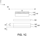
- FIG. 1C shows a cross-sectional view of a fast charging lithium-ion battery 10' according to another embodiment of the present disclosure.
- the fast charging lithium-ion battery 10' is different from the fast charging lithium-ion battery 10 in the arrangement of the positive active material layers and the negative active material layers on the positive current collector and the negative current collector, respectively, and similar designations or identical designations are used to indicate similar or identical elements.
- the positive active material layers 114' may be coated on one single surface of the positive current collector 112.
- the negative active material layers 134' may be coated on one single surface of the negative current collector 132.
- the positive active material layers 114' and the negative active material layers 134' may be a single-layer or a multi-layer structure.
- the fast charging lithium-ion battery was exemplified in comparison example 1 and embodiments 1-6.
- both the positive electrode plate and the negative electrode plate had a double-sided active material layers.
- All of the negative active material layers included titanium niobium oxide, and had a thickness (T) of 38.3 ⁇ m. All of the negative electrode plates had a width of 57 mm.
- the electrolyte was 1.2M lithium hexafluorophosphate (LiPF 6 ) salt in ethylene carbonate (EC)/dimethyl carbonate (DMC).
- the adhesive of the positive electrode plate and of the negative electrode plate both included polyvinylidene difluoride (PVDF).
- C-rates Charge and discharge rates of a battery are controlled by C-rates.
- C-rate “1C” means that it takes 1 hour when 1 Ampere current is provided to fully discharge a battery whose capacity is 1Ah.
- C-rate “0.5C” means that it takes 2 hour when 0.5 Ampere current is provided to fully discharge a battery whose capacity is 1Ah.
- C-rate “2C” means that it takes 0.5 hour when 2 Ampere current is provided to fully discharge a battery whose capacity is 1Ah.
- the lengths of the positive electrode plate and the negative electrode plate, the ratio (A/T) of the effective area of the negative active material layers to the thickness of the negative active material layers, and 0.5C charging/discharging ability used in comparison example 1 and embodiments 1-6 were listed in Table 1.
- FIGS. 2A-2G are diagrams showing the results of charging ability test performed in comparison example 1 and embodiments 1-6.
- FIG. 2A a diagram showing the results of charging ability test performed in comparison example 1 was shown.
- the X-axis coordinate represented the capacity (mAh)
- the Y-axis coordinate represented the voltage (V).
- the same discharging current such as the discharging current of 0.5C
- the charging currents such as the charging currents of 0.5C to 15C
- the charging process would stop once the preset voltage (such as 3V) was reached.
- 0.5C represented that, in theory, the current value adapted to discharge the fully charged battery in 2 hours.
- 4C represented that, in theory, the current value adapted to discharge the fully charged cell in 0.25 (1/4) hours.
- 4C represented high-power charging in comparison to 0.5C.
- a charging current of 0.5C was used.
- a charging current of 1C was used.
- a charging current of 3C was used.
- a charging current of 5C was used.
- a charging current of 7C was used.
- a charging current of 10C was used.
- a charging current of 12C was used.
- a charging current of 15C was used.
- FIGS. 2B-2G diagrams showing the results of charging ability test performed in embodiments 1 to 6 were shown.
- the same discharging current such as the discharging current of 0.5C
- the charging currents such as the charging currents of 0.5C to 15C
- the charging process would stop once the preset voltage (such as 3V) was reached.
- a charging current of 0.5C was used.
- a charging current of 1C was used.
- a charging current of 3C was used.
- a charging current of 4C was used.
- a charging current of 5C was used.
- a charging current of 7C was used.
- a charging current of 10C was used.
- a charging current of 12C was used.
- a charging current of 12C was used.
- a charging current of 12C was used.
- a charging current of 15C was used.
- FIGS. 3A-3G are diagrams showing the results of discharging ability test performed in comparison example 1 and embodiments 1-6.
- FIG. 3A a diagram showing the results of discharging ability test performed in comparison example 1 was shown.
- the X-axis coordinate represented the capacity (mAh), and the Y-axis coordinate represented the voltage (V).
- the same charging current such as the charging current of 0.5C
- the battery was fully charged by constant current constant voltage (CCCV) mode, but different discharging currents (such as the discharging currents of 0.5C to 15C) were used in the discharging test.
- 0.5C represented that, in theory, the current value adapted to discharge the fully charged battery in 2 hours.
- 4C represented that, in theory, the current value adapted to discharge the fully charged cell in 0.25 (1/4) hours.
- 4C represented high-power discharging in comparison to 0.5C.
- a discharging current of 0.5C was used.
- a discharging current of 1C was used.
- a discharging current of 3C was used.
- a discharging current of 5C was used.
- a discharging current of 7C was used.
- a discharging current of 10C was used.
- a discharging current of 12C was used.
- a discharging current of 15C was used.
- FIGS. 3B-3G diagrams showing the results of discharging ability test performed in embodiments 1-6 were shown.
- the same charging current such as the charging current of 0.5C
- the discharging currents such as the discharging currents of 0.5C to 15C
- a discharging current of 0.5C was used.
- a discharging current of 1C was used.
- a discharging current of 3C was used.
- a discharging current of 5C was used.
- a discharging current of 7C was used.
- a discharging current of 10C was used.
- a discharging current of 12C was used.
- a discharging current of 12C was used.
- a discharging current 15C was used.
- FIG. 4A is a diagram showing the capacity retention ratio obtained from the charging ability test performed in comparison example 1 and embodiments 1 to 6.
- the X-axis coordinate represented the number of charging tests.
- the charging current of 0.5C was used in the first to the second charging test.
- the charging current of 1C was used in the third to the fourth charging test.
- the charging current of 3C was used in the fifth to the sixth charging test.
- the charging current of 5C was used in the seventh to the eighth charging test.
- the charging current of 7C was used in the ninth to the tenth charging test.
- the charging current of 10C was used in the eleventh to the twelfth charging test.
- the charging current of 12C was used in the thirteenth to the fourteenth charging test.
- the charging current of 15C was used in the fifteenth to the sixteenth charging test.
- the Y-axis represented the capacity retention ratio (%), particularly the capacity retention ratio calculated in comparison example 1 and embodiments 1 to 6 under different charging currents when the battery was charged by a constant current (CC) and the capacity corresponding to 0.5C was regarded as 100%.
- the test result showed that under the 10C charging condition, the capacity retention ratio in comparison example 1 was smaller than 60%, but the capacity retention ratio in embodiments 1 to 6 was greater than 70% under the 10C charging condition. Since each ratio of the effective area of the negative active material layers to the thickness of the single side of the negative active material layers in embodiments 1 to 6 was greater than 2 ⁇ 10 5 mm, the battery had high-rate (such as 10C) charging ability.
- FIG. 4B is a diagram showing the capacity retention ratio obtained from the discharging ability test performed in comparison example 1 and embodiments 1 to 6.
- the X-axis coordinate represented the number of discharging tests.
- the discharging current of 0.5C was used in the first to the second discharging test.
- the discharging current of 1C was used in the third to the fourth discharging test.
- the discharging current of 3C was used in the fifth to the sixth discharging test.
- the discharging current of 5C was used in the seventh to the eighth discharging test.
- the discharging current 7C was used in the ninth to the tenth discharging test.
- the discharging current of 10C was used in the eleventh to the twelfth discharging test.
- the discharging current of 12C was used in the thirteenth to the fourteenth discharging test.
- the discharging current of 15C was used in the fifteenth to the sixteenth discharging test.
- the Y-axis represented the capacity retention ratio (%), particularly the capacity retention ratio calculated in comparison example 1 and embodiments 1 to 6 under different discharging currents when the battery was discharged by a constant current and the capacity corresponding to 0.5C was regarded as 100%.
- the test result showed that under the discharging condition corresponding to 10C, the capacity retention ratio in comparison example 1 was about 70%, but the capacity retention ratio in embodiments 1 to 6 was greater than 80%. Since all ratios of the effective area of the negative active material layers to the thickness of the single side of the negative active material layers in embodiments 1 to 6 was greater than 2 ⁇ 10 5 mm, the battery had high-rate (such as 10C) discharging ability.
- FIG. 5A is a diagram showing the results of capacity retention ratio obtained from the fast charging test performed in comparison example 1 and embodiments 1 to 6.
- the X-axis coordinate represented the ratio of the effective area of the negative active material layers to the thickness of the single side of the negative active material layers (A/T) (mm), that is, the ratio of the effective area of the negative active material layers to the thickness of the single side of the negative active material layers in comparison example 1 and embodiments 1 to 6.
- the Y-axis represented the capacity retention ratio (%), particularly the capacity retention ratio in different groups when the battery was charged by a constant current and the capacity corresponding to 0.5C was regarded as 100%. In group A1, the capacity retention ratio was obtained from the fast charging test performed in comparison example 1 and embodiments 1 to 6 when the battery was charged by the charging current of 10C.
- the capacity retention ratio was obtained from the fast charging test performed in comparison example 1 and embodiments 1 to 6 when the battery was charged by the charging current of 12C.
- the capacity retention ratio was obtained from the fast charging test performed in comparison example 1 and embodiments 1 to 6 when the battery was charged by the charging current of 15C.
- the test results showed that when the ratio (A/T) of the effective area of the negative active material layers to the thickness of the single side of the negative active material layers was equivalent to or was greater than 2.87 ⁇ 10 5 (such as embodiments 1 to 6), the capacity retention ratio obtained in group A1 is greater than 70%, it indicated that the battery had high-rate (such as 10C) fast charging ability.
- FIG. 5B is a diagram showing the capacity retention ratio obtained from the fast discharging test performed in comparison example 1 and embodiments 1 ⁇ 6.
- the X-axis coordinate represented the ratio (A/T) of the effective area of the negative active material layers to the thickness of the single side of the negative active material layers (mm), that is, the ratio of the effective area of the negative active material layers to the thickness of the single side of the negative active material layers in comparison example 1 and embodiments 1 to 6.
- the Y-axis represented the capacity retention ratio (%), particularly the capacity retention ratio calculated in different groups when the battery was charged by a constant current and the capacity corresponding to 0.5C was regarded as 100%. In group A2, the capacity retention ratio was obtained from the fast discharging test performed in comparison example 1 and embodiments 1 to 6 when the battery was discharged by a discharging current of 10C.
- the capacity retention ratio was obtained from the fast discharging test performed in comparison example 1 and embodiments 1 to 6 when the battery was discharged by the discharging current of 12C.
- the capacity retention ratio was obtained from the fast discharging test performed in comparison example 1 and embodiments 1 to 6 when the battery was discharged by the discharging current of 15C.
- the test results showed that when the ratio (A/T) of the effective area of the negative active material layers to the thickness of the single side of the negative active material layers was equivalent to or was greater than 2.87 ⁇ 10 5 (such as embodiments 1 to 6), the capacity retention ratio obtained in group A2 was greater than 80%, and it indicated that the battery had high-rate (such as 10C) fast discharging ability.
- the negative active material layers included a mixture of titanium niobium oxide (TNO) and lithium titanate (LTO) according to a weight ratio of 8:2, for example.
- TNO titanium niobium oxide
- LTO lithium titanate
- the ratio of the effective area (A/T) of the negative active material layers to the thickness of the single side of the negative active material layers was 1.44 ⁇ 10 5 .
- the ratio (A/T) of the effective area of the negative active material layers to the thickness of the single side of the negative active material layers was 2.87 ⁇ 10 5 .
- the ratio (A/T) of the effective area of the negative active material layers to the thickness of the single side of the negative active material layers was 4.31 ⁇ 10 5 .
- the materials of other structures of comparison example 2 and embodiments 7 to 8 were similar to the materials of other structures of comparison example 1 and embodiments 1 to 6.
- FIG. 6A is a diagram showing the results of capacity retention ratio obtained from the fast charging test performed in comparison example 2 and embodiments 7 to 8.
- the X-axis coordinate represented the ratio (A/T) of the effective area of the negative active material layers to the thickness of the single side of the negative active material layers (mm), that is, the ratio of the effective area of the negative active material layers to the thickness of the single side of the negative active material layers in comparison example 2 and embodiments 7 to 8.
- the Y-axis represented the capacity retention ratio (%), particularly the capacity retention ratio calculated in different groups when the battery was charged by a constant current and the capacity corresponding to 0.5C was regarded as 100%. In group A3, the capacity retention ratio was obtained from the fast charging test performed in comparison example 2 and embodiments 7 to 8 when the battery was charged by the charging current of 7C.
- the capacity retention ratio was obtained from the fast charging test performed in comparison example 2 and embodiments 7 to 8 when the battery was charged by the charging current of 10C.
- the capacity retention ratio was obtained from the fast charging test performed in comparison example 2 and embodiments 7 to 8 when the battery was charged by the charging current of 12C.
- the test result showed that when the ratio of the effective area of the negative active material layers to the thickness of the single side of the negative active material layers (A/T) was equivalent to or was greater than 2.87 ⁇ 10 5 (such as embodiments 7 to 8), the capacity retention ratio obtained in group B3 was greater than 70%, and it indicated that the battery had high-rate (such as 10C) fast charging ability.
- FIG. 6B is a diagram showing the results of capacity retention ratio obtained from the fast discharging test performed in comparison example 2 and embodiments 7 to 8.
- the X-axis coordinate represented the ratio (A/T) of the effective area of the negative active material layers to the thickness of the single side of the negative active material layers (mm), that is, the ratio of the effective area of the negative active material layers to the thickness of the single side of the negative active material layers in comparison example 2 and embodiments 7 to 8.
- the Y-axis represented the capacity retention ratio (%), particularly the capacity retention ratio calculated in different groups when the battery was discharged by a constant current and the capacity corresponding to 0.5C was regarded as 100%.
- group A4 the capacity retention ratio was obtained from the fast discharging test performed in comparison example 2 and embodiments 7 to 8 when the battery was discharged by the discharging current of a 7C.
- the capacity retention ratio was obtained from the fast discharging test performed in comparison example 2 and embodiments 7 to 8 when the battery was discharged by the discharging current of 10C.
- the capacity retention ratio was obtained from the fast discharging test performed in comparison example 2 and embodiments 7 to 8 when the battery was discharged by the discharging current of 12C.
- the test result showed that when the ratio (A/T) of the effective area of the negative active material layers to the thickness of the single side of the negative active material layers was equivalent to or was greater than 2.87 ⁇ 10 5 (such as embodiments 7 to 8), the capacity retention ratio obtained in group B4 was greater than 75%, and it indicated that the battery had high-rate (such as 10C) fast discharging ability.
- each ratio (A/T) of the effective area of the negative active material layers to the thickness (mm) of the single side of the negative active material layers in embodiments 7 to 8 was equivalent to or was greater than 2.87 ⁇ 10 5 , and the capacity retention ratio obtained from high-rate (such as 10C) charging and discharging processes was still very high, it could be concluded that the battery of the disclosure had high-rate charging or discharging ability.
- a lithium-ion battery includes a positive electrode plate, a negative electrode plate, a separator and an electrolyte.
- the positive electrode plate includes positive active material layers and the positive current collector
- the negative electrode plate includes a negative active material layers and a negative current collector, wherein the negative active material layers include titanium niobium oxide, lithium titanate or a combination thereof.
- the separator is disposed between the positive electrode plate and the negative electrode plate.
- the electrolyte contacts the positive electrode plate and the negative electrode plate.
- the negative active material layers have an effective area corresponding to the positive electrode plate.
- the negative active material layers have a thickness on one surface of the negative current collector. A ratio of the effective area to the thickness is greater than 2 ⁇ 10 5 mm.
- the ratio of the effective area of negative active material layers to the thickness of the single side of the negative active material layers is greater than 2 ⁇ 10 5 mm, such that the electron/ion transmission ability (that is, electrical conduction/electrochemical reaction ability) can be increased, and the lithium-ion battery can achieve a faster charging rate and a faster discharging rate. Therefore, the charging ability and the discharging ability of the lithium-ion battery can be increased, the market competitiveness of the lithium-ion battery of the disclosure can be enhanced, and the application field of the lithium-ion battery can be expanded.
Landscapes
- Chemical & Material Sciences (AREA)
- Engineering & Computer Science (AREA)
- Chemical Kinetics & Catalysis (AREA)
- Electrochemistry (AREA)
- General Chemical & Material Sciences (AREA)
- Materials Engineering (AREA)
- Manufacturing & Machinery (AREA)
- Composite Materials (AREA)
- Inorganic Chemistry (AREA)
- Secondary Cells (AREA)
- Battery Electrode And Active Subsutance (AREA)
Applications Claiming Priority (2)
| Application Number | Priority Date | Filing Date | Title |
|---|---|---|---|
| US201962901814P | 2019-09-18 | 2019-09-18 | |
| TW109117553 | 2020-05-26 |
Publications (1)
| Publication Number | Publication Date |
|---|---|
| EP3796424A1 true EP3796424A1 (en) | 2021-03-24 |
Family
ID=72561645
Family Applications (1)
| Application Number | Title | Priority Date | Filing Date |
|---|---|---|---|
| EP20196883.1A Pending EP3796424A1 (en) | 2019-09-18 | 2020-09-18 | Fast charging lithium-ion battery |
Country Status (4)
| Country | Link |
|---|---|
| US (1) | US20210083279A1 (ja) |
| EP (1) | EP3796424A1 (ja) |
| JP (1) | JP7078682B2 (ja) |
| CN (1) | CN112531217A (ja) |
Families Citing this family (1)
| Publication number | Priority date | Publication date | Assignee | Title |
|---|---|---|---|---|
| CN113346125A (zh) * | 2021-05-31 | 2021-09-03 | 廖福宁 | 一种锂离子电池 |
Citations (3)
| Publication number | Priority date | Publication date | Assignee | Title |
|---|---|---|---|---|
| US20080020278A1 (en) * | 2004-10-29 | 2008-01-24 | Medtronic, Inc. | Lithium-ion battery |
| KR20180023688A (ko) * | 2016-08-26 | 2018-03-07 | 주식회사 엘지화학 | 얇은 두께의 전극 활물질 층을 포함하는 전극을 구비한 이차전지 |
| US20190097271A1 (en) * | 2018-05-16 | 2019-03-28 | Contemporary Amperex Technology Co., Limited | Negative electrode plate and secondary battery comprising the same |
Family Cites Families (9)
| Publication number | Priority date | Publication date | Assignee | Title |
|---|---|---|---|---|
| US8617745B2 (en) * | 2004-02-06 | 2013-12-31 | A123 Systems Llc | Lithium secondary cell with high charge and discharge rate capability and low impedance growth |
| CN100483837C (zh) * | 2004-07-28 | 2009-04-29 | 比亚迪股份有限公司 | 大倍率锂离子二次电池 |
| TWI270994B (en) * | 2005-12-29 | 2007-01-11 | Ind Tech Res Inst | High rate capability design of lithium ion secondary battery |
| CN100502127C (zh) * | 2006-01-26 | 2009-06-17 | 财团法人工业技术研究院 | 具有大电流放电能力的锂离子二次电池 |
| JP4516588B2 (ja) * | 2007-09-05 | 2010-08-04 | セイコーエプソン株式会社 | 全固体リチウム二次電池および全固体リチウム二次電池の製造方法 |
| WO2017046895A1 (ja) * | 2015-09-16 | 2017-03-23 | 株式会社 東芝 | 組電池及び電池パック |
| CN105428636A (zh) * | 2015-11-24 | 2016-03-23 | 四川省有色冶金研究院有限公司 | 一种基于钛酸锂的锂离子电池负极材料及其制备方法 |
| JP7080584B2 (ja) * | 2017-03-17 | 2022-06-06 | 株式会社東芝 | 二次電池、電池パック、および車両 |
| BR112020018102A2 (pt) * | 2018-03-30 | 2020-12-22 | Kabushiki Kaisha Toshiba | Grupo de eletrodos, bateria e pacote de bateria |
-
2020
- 2020-09-18 US US17/026,021 patent/US20210083279A1/en active Pending
- 2020-09-18 EP EP20196883.1A patent/EP3796424A1/en active Pending
- 2020-09-18 CN CN202010986246.6A patent/CN112531217A/zh active Pending
- 2020-09-18 JP JP2020157826A patent/JP7078682B2/ja active Active
Patent Citations (3)
| Publication number | Priority date | Publication date | Assignee | Title |
|---|---|---|---|---|
| US20080020278A1 (en) * | 2004-10-29 | 2008-01-24 | Medtronic, Inc. | Lithium-ion battery |
| KR20180023688A (ko) * | 2016-08-26 | 2018-03-07 | 주식회사 엘지화학 | 얇은 두께의 전극 활물질 층을 포함하는 전극을 구비한 이차전지 |
| US20190097271A1 (en) * | 2018-05-16 | 2019-03-28 | Contemporary Amperex Technology Co., Limited | Negative electrode plate and secondary battery comprising the same |
Also Published As
| Publication number | Publication date |
|---|---|
| JP7078682B2 (ja) | 2022-05-31 |
| CN112531217A (zh) | 2021-03-19 |
| US20210083279A1 (en) | 2021-03-18 |
| JP2021048130A (ja) | 2021-03-25 |
Similar Documents
| Publication | Publication Date | Title |
|---|---|---|
| US11114659B2 (en) | Negative electrode sheet and secondary battery | |
| WO2020078357A1 (zh) | 二次电池 | |
| US20110206962A1 (en) | Nonaqueous electrolyte secondary battery and method for manufacturing the same | |
| KR102122467B1 (ko) | 리튬 이차전지용 전극 및 이를 포함하는 리튬 이차전지 | |
| US20200058914A1 (en) | Nonaqueous electrolyte secondary battery | |
| KR101249349B1 (ko) | 리튬 이차 전지용 음극활물질 및 이를 이용한 리튬 이차 전지 | |
| US11158884B2 (en) | All solid state battery | |
| KR20070026233A (ko) | 비수 전해액 이차전지 | |
| CN112820855B (zh) | 极片及电池 | |
| KR20170136878A (ko) | 리튬 이차 전지용 음극 활물질, 이를 포함하는 음극 및 리튬 이차 전지 | |
| KR20150003665A (ko) | 리튬 이차 전지 | |
| US20240128601A1 (en) | Electrode piece, rolled core and battery | |
| JP2020510980A (ja) | 円筒形ゼリーロールに使用されるストリップ型電極及びそれを含むリチウム二次電池 | |
| EP3796424A1 (en) | Fast charging lithium-ion battery | |
| EP3641026A1 (en) | Secondary battery | |
| TWI741800B (zh) | 快充鋰離子電池 | |
| JP2013044701A (ja) | 電池システム | |
| US20230223510A1 (en) | Secondary battery and method for manufacturing the same | |
| US20230090463A1 (en) | Battery | |
| EP3131149B1 (en) | Flat-type secondary battery | |
| EP3641025A1 (en) | Secondary battery | |
| KR101307427B1 (ko) | 미세 엠보싱이 부여된 리튬이차전지용 분리막 및 이를 포함하는 리튬이차전지 | |
| KR20190042850A (ko) | 리튬 이차 전지 | |
| KR20140008957A (ko) | 접착력과 고율 특성이 향상된 음극 및 이를 포함하는 리튬 이차 전지 | |
| CN113097440A (zh) | 电化学装置及用电设备 |
Legal Events
| Date | Code | Title | Description |
|---|---|---|---|
| PUAI | Public reference made under article 153(3) epc to a published international application that has entered the european phase |
Free format text: ORIGINAL CODE: 0009012 |
|
| STAA | Information on the status of an ep patent application or granted ep patent |
Free format text: STATUS: REQUEST FOR EXAMINATION WAS MADE |
|
| 17P | Request for examination filed |
Effective date: 20200918 |
|
| AK | Designated contracting states |
Kind code of ref document: A1 Designated state(s): AL AT BE BG CH CY CZ DE DK EE ES FI FR GB GR HR HU IE IS IT LI LT LU LV MC MK MT NL NO PL PT RO RS SE SI SK SM TR |
|
| AX | Request for extension of the european patent |
Extension state: BA ME |
|
| RBV | Designated contracting states (corrected) |
Designated state(s): AL AT BE BG CH CY CZ DE DK EE ES FI FR GB GR HR HU IE IS IT LI LT LU LV MC MK MT NL NO PL PT RO RS SE SI SK SM TR |
|
| GRAP | Despatch of communication of intention to grant a patent |
Free format text: ORIGINAL CODE: EPIDOSNIGR1 |
|
| STAA | Information on the status of an ep patent application or granted ep patent |
Free format text: STATUS: GRANT OF PATENT IS INTENDED |
|
| INTG | Intention to grant announced |
Effective date: 20240418 |