EP3795554B1 - Method for producing halogenated propanes - Google Patents
Method for producing halogenated propanes Download PDFInfo
- Publication number
- EP3795554B1 EP3795554B1 EP20199542.0A EP20199542A EP3795554B1 EP 3795554 B1 EP3795554 B1 EP 3795554B1 EP 20199542 A EP20199542 A EP 20199542A EP 3795554 B1 EP3795554 B1 EP 3795554B1
- Authority
- EP
- European Patent Office
- Prior art keywords
- reactor
- zone
- still
- catalyst
- carbon tetrachloride
- Prior art date
- Legal status (The legal status is an assumption and is not a legal conclusion. Google has not performed a legal analysis and makes no representation as to the accuracy of the status listed.)
- Active
Links
Images
Classifications
-
- C—CHEMISTRY; METALLURGY
- C07—ORGANIC CHEMISTRY
- C07C—ACYCLIC OR CARBOCYCLIC COMPOUNDS
- C07C17/00—Preparation of halogenated hydrocarbons
- C07C17/26—Preparation of halogenated hydrocarbons by reactions involving an increase in the number of carbon atoms in the skeleton
- C07C17/263—Preparation of halogenated hydrocarbons by reactions involving an increase in the number of carbon atoms in the skeleton by condensation reactions
- C07C17/266—Preparation of halogenated hydrocarbons by reactions involving an increase in the number of carbon atoms in the skeleton by condensation reactions of hydrocarbons and halogenated hydrocarbons
-
- B—PERFORMING OPERATIONS; TRANSPORTING
- B01—PHYSICAL OR CHEMICAL PROCESSES OR APPARATUS IN GENERAL
- B01D—SEPARATION
- B01D3/00—Distillation or related exchange processes in which liquids are contacted with gaseous media, e.g. stripping
- B01D3/14—Fractional distillation or use of a fractionation or rectification column
- B01D3/32—Other features of fractionating columns ; Constructional details of fractionating columns not provided for in groups B01D3/16 - B01D3/30
- B01D3/322—Reboiler specifications
-
- B—PERFORMING OPERATIONS; TRANSPORTING
- B01—PHYSICAL OR CHEMICAL PROCESSES OR APPARATUS IN GENERAL
- B01F—MIXING, e.g. DISSOLVING, EMULSIFYING OR DISPERSING
- B01F27/00—Mixers with rotary stirring devices in fixed receptacles; Kneaders
- B01F27/05—Stirrers
- B01F27/11—Stirrers characterised by the configuration of the stirrers
- B01F27/112—Stirrers characterised by the configuration of the stirrers with arms, paddles, vanes or blades
-
- B—PERFORMING OPERATIONS; TRANSPORTING
- B01—PHYSICAL OR CHEMICAL PROCESSES OR APPARATUS IN GENERAL
- B01F—MIXING, e.g. DISSOLVING, EMULSIFYING OR DISPERSING
- B01F27/00—Mixers with rotary stirring devices in fixed receptacles; Kneaders
- B01F27/80—Mixers with rotary stirring devices in fixed receptacles; Kneaders with stirrers rotating about a substantially vertical axis
- B01F27/90—Mixers with rotary stirring devices in fixed receptacles; Kneaders with stirrers rotating about a substantially vertical axis with paddles or arms
-
- B—PERFORMING OPERATIONS; TRANSPORTING
- B01—PHYSICAL OR CHEMICAL PROCESSES OR APPARATUS IN GENERAL
- B01F—MIXING, e.g. DISSOLVING, EMULSIFYING OR DISPERSING
- B01F35/00—Accessories for mixers; Auxiliary operations or auxiliary devices; Parts or details of general application
- B01F35/50—Mixing receptacles
- B01F35/53—Mixing receptacles characterised by the configuration of the interior, e.g. baffles for facilitating the mixing of components
- B01F35/531—Mixing receptacles characterised by the configuration of the interior, e.g. baffles for facilitating the mixing of components with baffles, plates or bars on the wall or the bottom
- B01F35/5312—Mixing receptacles characterised by the configuration of the interior, e.g. baffles for facilitating the mixing of components with baffles, plates or bars on the wall or the bottom with vertical baffles mounted on the walls
-
- B—PERFORMING OPERATIONS; TRANSPORTING
- B01—PHYSICAL OR CHEMICAL PROCESSES OR APPARATUS IN GENERAL
- B01J—CHEMICAL OR PHYSICAL PROCESSES, e.g. CATALYSIS OR COLLOID CHEMISTRY; THEIR RELEVANT APPARATUS
- B01J19/00—Chemical, physical or physico-chemical processes in general; Their relevant apparatus
- B01J19/0053—Details of the reactor
- B01J19/006—Baffles
-
- B—PERFORMING OPERATIONS; TRANSPORTING
- B01—PHYSICAL OR CHEMICAL PROCESSES OR APPARATUS IN GENERAL
- B01J—CHEMICAL OR PHYSICAL PROCESSES, e.g. CATALYSIS OR COLLOID CHEMISTRY; THEIR RELEVANT APPARATUS
- B01J19/00—Chemical, physical or physico-chemical processes in general; Their relevant apparatus
- B01J19/18—Stationary reactors having moving elements inside
-
- B—PERFORMING OPERATIONS; TRANSPORTING
- B01—PHYSICAL OR CHEMICAL PROCESSES OR APPARATUS IN GENERAL
- B01J—CHEMICAL OR PHYSICAL PROCESSES, e.g. CATALYSIS OR COLLOID CHEMISTRY; THEIR RELEVANT APPARATUS
- B01J23/00—Catalysts comprising metals or metal oxides or hydroxides, not provided for in group B01J21/00
- B01J23/70—Catalysts comprising metals or metal oxides or hydroxides, not provided for in group B01J21/00 of the iron group metals or copper
- B01J23/74—Iron group metals
- B01J23/745—Iron
-
- C—CHEMISTRY; METALLURGY
- C07—ORGANIC CHEMISTRY
- C07C—ACYCLIC OR CARBOCYCLIC COMPOUNDS
- C07C17/00—Preparation of halogenated hydrocarbons
- C07C17/26—Preparation of halogenated hydrocarbons by reactions involving an increase in the number of carbon atoms in the skeleton
- C07C17/272—Preparation of halogenated hydrocarbons by reactions involving an increase in the number of carbon atoms in the skeleton by addition reactions
- C07C17/275—Preparation of halogenated hydrocarbons by reactions involving an increase in the number of carbon atoms in the skeleton by addition reactions of hydrocarbons and halogenated hydrocarbons
-
- C—CHEMISTRY; METALLURGY
- C07—ORGANIC CHEMISTRY
- C07C—ACYCLIC OR CARBOCYCLIC COMPOUNDS
- C07C17/00—Preparation of halogenated hydrocarbons
- C07C17/361—Preparation of halogenated hydrocarbons by reactions involving a decrease in the number of carbon atoms
-
- C—CHEMISTRY; METALLURGY
- C07—ORGANIC CHEMISTRY
- C07C—ACYCLIC OR CARBOCYCLIC COMPOUNDS
- C07C17/00—Preparation of halogenated hydrocarbons
- C07C17/38—Separation; Purification; Stabilisation; Use of additives
-
- C—CHEMISTRY; METALLURGY
- C07—ORGANIC CHEMISTRY
- C07C—ACYCLIC OR CARBOCYCLIC COMPOUNDS
- C07C17/00—Preparation of halogenated hydrocarbons
- C07C17/38—Separation; Purification; Stabilisation; Use of additives
- C07C17/383—Separation; Purification; Stabilisation; Use of additives by distillation
-
- C—CHEMISTRY; METALLURGY
- C07—ORGANIC CHEMISTRY
- C07C—ACYCLIC OR CARBOCYCLIC COMPOUNDS
- C07C19/00—Acyclic saturated compounds containing halogen atoms
- C07C19/01—Acyclic saturated compounds containing halogen atoms containing chlorine
-
- B—PERFORMING OPERATIONS; TRANSPORTING
- B01—PHYSICAL OR CHEMICAL PROCESSES OR APPARATUS IN GENERAL
- B01F—MIXING, e.g. DISSOLVING, EMULSIFYING OR DISPERSING
- B01F2101/00—Mixing characterised by the nature of the mixed materials or by the application field
- B01F2101/2204—Mixing chemical components in generals in order to improve chemical treatment or reactions, independently from the specific application
-
- B—PERFORMING OPERATIONS; TRANSPORTING
- B01—PHYSICAL OR CHEMICAL PROCESSES OR APPARATUS IN GENERAL
- B01J—CHEMICAL OR PHYSICAL PROCESSES, e.g. CATALYSIS OR COLLOID CHEMISTRY; THEIR RELEVANT APPARATUS
- B01J2219/00—Chemical, physical or physico-chemical processes in general; Their relevant apparatus
- B01J2219/00049—Controlling or regulating processes
- B01J2219/00182—Controlling or regulating processes controlling the level of reactants in the reactor vessel
-
- B—PERFORMING OPERATIONS; TRANSPORTING
- B01—PHYSICAL OR CHEMICAL PROCESSES OR APPARATUS IN GENERAL
- B01J—CHEMICAL OR PHYSICAL PROCESSES, e.g. CATALYSIS OR COLLOID CHEMISTRY; THEIR RELEVANT APPARATUS
- B01J2219/00—Chemical, physical or physico-chemical processes in general; Their relevant apparatus
- B01J2219/00761—Details of the reactor
- B01J2219/00763—Baffles
- B01J2219/00765—Baffles attached to the reactor wall
- B01J2219/00768—Baffles attached to the reactor wall vertical
Definitions
- Embodiments of the present invention are directed toward methods for the production of chlorinated propanes prepared by reacting carbon tetrachloride with an olefin.
- hydrofluorocarbons such as those used as refrigerants and blowing agents, are prepared from hydrochlorocarbon feedstocks.
- hydrochlorocarbon feedstocks such as 1,1,1,3,3-pentafluoropropane (HFC-245fa) is a widely employed hydrofluorocarbon that, according to U.S. Patent No. 6,313,360 , can be prepared from a 1,1,1,3,3-pentachloropropane (HCC-240fa) feedstock.
- the 1,1,1,3,3-pentachloropropane can be synthesized by reacting carbon tetrachloride with vinyl chloride in the presence of an iron catalyst and tributylphosphate.
- Vinyl chloride is fed to the reactor as a liquid or vapor, and metallic iron, preferably in the form of a slurry within carbon tetrachloride, is added to the reactor.
- metallic iron preferably in the form of a slurry within carbon tetrachloride
- the reactor contents are continually drawn from the reactor, preferably through a sedimentation tube, in order to maintain the unconverted metallic iron within the reactor. This process is enhanced by drawing the reactor effluent from a still zone created within the reactor.
- the reactor effluent is distilled to recover catalyst and ultimately isolate the desired 1,1,1,3,3-pentachloropropane product.
- U.S. Publ. No. 2012/0310020 suggests that the formation of polyvinyl chloride within the reactor can be reduced by feeding the vinyl chloride as a vapor through a dip tube or sponge-type gas diffuser into a reactor precharged with carbon tetrachloride, tributylphosphate, and iron powder.
- Hydrofluoroolefins have been targeted as replacements for hydrofluorocarbons.
- 2,3,3,3-tetrafluoropropene HFO-1234yf
- R-134a 1,1,1,2-tetrafluoroethane
- chlorinated organics play an important role in the synthesis of hydrofluoroolefins.
- HCC-1230xa 1,1,2,3-tetrachloropropene
- HFO-1234yf 2,3,3,3-tetrafluoropropane
- U.S. Publ. No. 2009/0216055 teaches that 1,1,2,3-tetrachloropropene (HCC-1230xa) can be prepared by dehydrochlorinating 1,1,1,2,3-pentachloropropane, and that the 1,1,1,2,3-pentachloropropane can be prepared within a single reactor by reacting 1,1,1,3-tetrachloropropane (HCC-250fb) with chlorine in the presence of a Lewis acid. According to U.S. Publ. No.
- 1,1,1,3-tetrachloropropane can be synthesized by reacting carbon tetrachloride with ethylene in the presence of metallic iron, dissolved iron (II), iron (III) compounds, and an organophosphate cocatalyst.
- metallic iron dissolved iron (II), iron (III) compounds
- organophosphate cocatalyst U.S. Publ. No. 2004/0225166 teaches that the reactor in which the carbon tetrachloride and ethylene are reacted is agitated to provide adequate contact of the liquid reactants with the surface of the metallic iron, to provide adequate contact of the liquid reactants with the vapor in the reactor headspace so that ethylene is readily dissolved in the liquid, and to provide adequate contact of the reaction mixture with heat-transfer surfaces to thereby enable adequate temperature control.
- 1,1,1,3-tetrachloropropane is an important halogenated propane, there remains a desire to improve synthetic techniques employed in its preparation.
- the present invention provides a process for preparing chlorinated propanes according to claim 1 or claim 3. A further embodiment is disclosed in the dependent claim.
- Embodiments of the invention are based, at least in part, on the discovery of a method for producing chlorinated propanes.
- chlorinated propanes are prepared by reacting carbon tetrachloride with an olefin (e.g. ethylene) in the presence of an iron-based catalyst, and the chlorinated propanes are removed from the reaction zone through a conically-shaped effluent nozzle drawing from a still zone created within the reactor.
- the still zone is configured to minimize liquid flow velocity and thereby maximize iron sedimentation while allowing gaseous reactants to rise to the reactor headspace.
- the processes of the invention generally relate to the preparation of chlorinated hydrocarbons by reacting carbon tetrachloride with an olefin.
- These reactions are generally known in the art, and disclosed in U.S. Patent No. 6,313,360 and U.S. Publ. Nos. 2004/0225166 and 2009/0216055 .
- Practice of embodiments of the invention are not necessarily limited by the olefin employed as a reactant, although common olefins for use in these reactions include ethylene and vinyl chloride.
- ethylene is a gaseous olefin, and therefore embodiments of the invention may provide distinct advantages where ethylene is employed as a reactant.
- insoluble or partially soluble catalysts may be used in conjunction with cocatalysts or ligands, which are believed to complement the catalyst; for example, tributylphosphate has been used in conjunction with an iron catalyst.
- tributylphosphate has been used in conjunction with an iron catalyst.
- embodiments of the invention may be described with reference to tributylphosphate as a cocatalyst or ligand used in conjunction with iron, the skilled person will appreciate that the invention can be extended to the use of other cocatalysts or ligands.
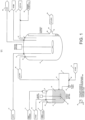
- system 11 includes iron slurry mix tank 21, which is in fluid communication with reactor 51 (which may be referred to as addition reactor 51) through a conduit loop 41.
- Slurry tank 21 receives carbon tetrachloride 31 through inlet 22 and iron powder 33 through inlet 23.
- Slurry tank 21 may also optionally receive other materials 34, such as additional solvents, catalysts, catalyst ligands, or recycle streams captured downstream in the process, through inlet 26.
- Carbon tetrachloride 31 may be fed continuously, or it may be periodically injected, into slurry tank 21 through inlet 22.
- iron powder 33 may be periodically added to slurry tank 21, or, iron powder 33 may be continuously charged to slurry tank 21 by employing continuous feeding apparatus.
- iron powder 33 can be charged to slurry tank 21 by employing a dustless bucket tipper.
- a slurry 35 of carbon tetrachloride 31 and iron powder 33 is formed by agitating the mixture within slurry tank 21 via one or more mixing elements 24, which may include agitation devices or baffles.
- Mixing elements 24 may be operated in a manner to substantially disperse the catalyst (e.g. iron) within the chlorinated hydrocarbon liquid (e.g. carbon tetrachloride); agitation is sufficient to achieve a substantially homogenous concentration of the catalyst within the carbon tetrachloride.
- Slurry 35 is continuously circulated through a conduit loop 41 via one or more pumps 43 that are upstream of reactor 51, which pumps may also advantageously maintain pressure within loop 41. Adequate pressure may also be maintained within loop 41 through the assistance of a back-pressure valve 46, which is downstream of where loop 41 delivers slurry 35 to reactor 51 (i.e. downstream of valve 47 within loop 41). Slurry 35 moving through loop 41 may be heated or cooled by heating or cooling elements 45. Other materials 34, such as those described above, may also optionally be injected into loop 41. Mixing of the various constituents within slurry 35 can be enhanced by one or more in-line mixers, which are not shown. Circulation loop 41 also includes valve 47 that, when in the open position, allows slurry 35 to feed reactor 51. When valve 47 is in its closed position, slurry 35 circulates through loop 41 back to mix tank 21. Valve 47 may include a control valve or solenoid valve that can be controlled by a signal flow sensor or similar device.
- Reactor 51 receives slurry 35 from loop 41 via inlet 53. Reactor 51 also receives olefin 61, such as ethylene, via inlet 55. Additionally, and as will be explained in greater detail below, reactor 51 may also optionally receive other material inputs 34, such as those described above, via additional inlet 57. Reactor effluent 63 exits reactor 51 at outlet 59. Volatiles can be vented through outlet 58.
- the flow of slurry 35 into reactor 51 which flow is at least partially regulated by valve 47, can be proportional to the olefin 61 feed rate into reactor 51.
- Loop 41 can be maintained at a pressure that is greater than the pressure within reactor 51;the pressure within loop 41 may be sufficient to create flow into reactor 51 (when valve 47 is open) while taking into account potential gravitational assistance. As the skilled person will appreciate, sufficient pressure can be maintained within loop 41 while valve 47 provides flow into reactor 51 by back-pressure valve 46.
- Valve 46 may include a control valve or solenoid valve that can be controlled by a signal flow sensor or similar device. Temperature controls (e.g. element 45) may provide cooling to maintain the temperature of slurry 35 below the boiling point of the chlorinated hydrocarbon (e.g. below 77 °C for carbon tetrachloride). The loop temperature may be maintained at from about 0 to about 80 °C, from about 5 to about 60 °C, and from about 10 to about 40 °C.
- the concentration of iron powder 33 within slurry 35 may be represented as a percent solids within the weight of liquid.
- the percent solids iron powder within slurry 35 may be from about 0.02 to about 5.0 wt %, from about 0.03 to about 1.0 wt %, and from about 0.05 to about 0.2 wt %.
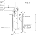
- Reactor 51 can be further described with reference to Fig. 2 , which shows slurry 35 entering reactor 51 at inlet 53, as well as olefin 61 (e.g. ethylene) entering at inlet 55, and other optional materials, such as tributylphosphate ligand 69 and catalyst recycle stream 65, entering via inlet 57.
- olefin 61 e.g. ethylene
- tributylphosphate ligand 69 and catalyst recycle stream 65 entering via inlet 57.
- the contents of the reactor form a liquid level 67, which is the liquid level upon aeration, and the skilled person will appreciate that the liquid level will be lower when still (i.e. not aerated).
- Reactor 51 may generally include a tank reactor of the type known in the art (e.g. a CSTR).
- the charging of slurry 35, olefin 61, and other materials 69, 65 may take place by injecting the materials below the liquid level 67 within reactor 51. As the skilled person will appreciate, this may take place by the use of dip tubes, as well as various nozzles or diffusion devices. Olefin 61 may be injected at a location proximate to the bottom end 71 of reactor 51. Olefin 61 may be injected at or near mixing elements 73 of mixing device 75. One or more of the reactants or catalysts may be injected above liquid level 67 (i.e.
- reactor effluent 63 exits reactor 51 via outlet 59.
- Agitation device 75 may include a conduit that provides gaseous communication between headspace 68 and liquid mixture (i.e. slurry 35) below the liquid level 67. As a result, volatile compounds, especially ethylene, within the headspace can be returned to liquid mixture 64 to facilitate the desired reaction.
- Agitation device 75 may be an aspirating agitator. As the skilled person appreciates, these agitators draw gaseous materials (e.g. ethylene) from the head space and reintroduce the gaseous materials into the reaction zone (i.e. into liquid mixture 64).
- Agitation device 75 may be operated at a power to volume ratio of at least 10 kilowatts per cubic meter (kW/m 3 ), at least 30 kW/m 3 , at least 50 kW/m 3 , and from about 10 to about 100 kW/m 3 .
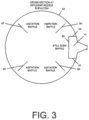
- reactor 51 includes one or more agitation baffles 81, 83, 85, and 87. Each of these respective agitation baffles (81, 83, 85, 87) are attached to the wall of the reactor (or to the top or bottom of the reactor). The dimensions and geometry of agitation baffles are known in the art.
- reactor 51 is equipped with a still-zone baffle 91.
- Still-zone baffle 91 includes opposed walls 93, 97, which are each respectively attached to circumferential wall 52 of reactor 51.
- Still-zone baffle 91 also includes interconnecting wall 95 connecting opposed walls 93, 97 to thereby form still zone 92.
- Still zone baffle 91 partially extends across the height 54 of wall 52 in order to provide a baffle gap 99 (best shown in Fig. 2 ) proximate to bottom 71 of reactor 51.
- still-zone baffle 91 has a height that extends above liquid level line 67 at its upper end 96, and at its lower end 94 does not contact bottom 71 of reactor 51 so as to provide a gap 99 through which liquid can flow.
- Still-zone baffle 91 is positioned within reactor 51 to surround outlet 59. As a result, reactor effluent 63 must enter still zone 92 formed by still-zone baffle 91 via baffle gap 99 in order to exit outlet 59.
- outlet 59 is equipped with a conically shaped effluent nozzle 62, wherein wide end 66 is attached to reactor wall 52. This configuration further inhibits gas entrainment within effluent 63. Also, the height of outlet 59, relative to the height of the reactor, is designed to avoid substantial or appreciable turbulence that is present at the bottom of the reactor. The skilled person will appreciate that outlet 59 is nonetheless positioned relatively low within the reactor to provide for the ability to empty the contents of the reactor when desired.
- gaseous reactants e.g. ethylene
- the velocity of liquid medium 64 traveling through baffle gap 99 is less than 0.0015, in other embodiments less than 0.0009, and in other embodiments less than 0.0006 m/s.
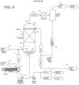
- column 103 includes a bottom zone 103A, where column bottoms 106 in the form of liquid collect and form liquid level 106A, packing zone 103B, where packing materials and/or trays are located, and head space 103C through which vapor passes out of column 103.
- Distillation column 103 and reboiler 123 are in fluid communication via reboiler loop 111.
- Crude 63 enters column 103 at bottom 103A at or near liquid level 106A, where crude 63 becomes included in column bottoms 106 at the bottom of distillation column 103.
- Column bottoms 106 (which include the target chlorinated propanes) enter loop 111 from outlet 105.
- the velocity of column bottoms 106 flowing through loop 111 is regulated by, for example, pump 115.
- the velocity of the column bottoms flowing through loop 111 may be maintained at a rate sufficient to reduce tube wall temperatures within reboiler 123 and thereby inhibit reactions and/or the formation of deposits within reboiler 123.
- Column bottoms 106 enter reboiler 123 at inlet 125 and circulate tube side within reboiler 123.
- the velocity of column bottoms 106 through reboiler 123 may be at least 1, at least 3, and at least 5 m/s.
- the velocity of column bottoms 106 through reboiler 123 may be from about 1 to about 20, from about 2 to about 12, and from about 3 to about 9 m/s.
- column bottoms 106 travel tube side through reboiler 123 where they are subjected to heat that is transferred from heating fluid steam 127 (e.g. steam) introduced through inlet 126 shell side of bottoms 106.
- Heat flux across the tubes within reboiler 123 may beless than 44, less than 33, and less than 22 kW/m 2 .
- the heat flux across the tubes within reboiler 123 is from about 5 to about 44, from about 7 to about 33, and from about 10 to about 22 kW/m 2 .
- the desired chlorinated hydrocarbons will exit distillation column 103 as a vapor stream 132 through vapor outlet 109 of distillation column 103.
- Vapor stream 132 may then be routed through condenser 136, which causes the condensation of the desired chlorinated hydrocarbon 138 (e.g. 1,1,1,3-tetrachloropropane), which may also be referred to as condensate stream 138, while allowing lighter materials (as well as uncondensable materials) to exit as a light-end stream 140.
- a portion of condensate stream 138 may be routed back to column 103 via a distributor (not shown) and into head space 103C to reflux the packing. The remainder of condensate 138 is collected as the desired product.
- further distillation and purification of condensate stream 138 can be accomplished in downstream processing.
Landscapes
- Chemical & Material Sciences (AREA)
- Organic Chemistry (AREA)
- Chemical Kinetics & Catalysis (AREA)
- Engineering & Computer Science (AREA)
- Materials Engineering (AREA)
- Organic Low-Molecular-Weight Compounds And Preparation Thereof (AREA)
- Low-Molecular Organic Synthesis Reactions Using Catalysts (AREA)
Priority Applications (1)
| Application Number | Priority Date | Filing Date | Title |
|---|---|---|---|
| EP24201334.0A EP4530279A1 (en) | 2016-07-26 | 2017-07-24 | Method for producing halogenated propanes |
Applications Claiming Priority (3)
| Application Number | Priority Date | Filing Date | Title |
|---|---|---|---|
| US201662366674P | 2016-07-26 | 2016-07-26 | |
| EP17761938.4A EP3490965B1 (en) | 2016-07-26 | 2017-07-24 | Methods for producing halogenated propanes |
| PCT/US2017/043469 WO2018022488A1 (en) | 2016-07-26 | 2017-07-24 | Methods for producing halogenated propanes |
Related Parent Applications (2)
| Application Number | Title | Priority Date | Filing Date |
|---|---|---|---|
| EP17761938.4A Division EP3490965B1 (en) | 2016-07-26 | 2017-07-24 | Methods for producing halogenated propanes |
| EP17761938.4A Division-Into EP3490965B1 (en) | 2016-07-26 | 2017-07-24 | Methods for producing halogenated propanes |
Related Child Applications (1)
| Application Number | Title | Priority Date | Filing Date |
|---|---|---|---|
| EP24201334.0A Division EP4530279A1 (en) | 2016-07-26 | 2017-07-24 | Method for producing halogenated propanes |
Publications (2)
| Publication Number | Publication Date |
|---|---|
| EP3795554A1 EP3795554A1 (en) | 2021-03-24 |
| EP3795554B1 true EP3795554B1 (en) | 2024-10-02 |
Family
ID=59791114
Family Applications (3)
| Application Number | Title | Priority Date | Filing Date |
|---|---|---|---|
| EP20199542.0A Active EP3795554B1 (en) | 2016-07-26 | 2017-07-24 | Method for producing halogenated propanes |
| EP17761938.4A Active EP3490965B1 (en) | 2016-07-26 | 2017-07-24 | Methods for producing halogenated propanes |
| EP24201334.0A Pending EP4530279A1 (en) | 2016-07-26 | 2017-07-24 | Method for producing halogenated propanes |
Family Applications After (2)
| Application Number | Title | Priority Date | Filing Date |
|---|---|---|---|
| EP17761938.4A Active EP3490965B1 (en) | 2016-07-26 | 2017-07-24 | Methods for producing halogenated propanes |
| EP24201334.0A Pending EP4530279A1 (en) | 2016-07-26 | 2017-07-24 | Method for producing halogenated propanes |
Country Status (13)
| Country | Link |
|---|---|
| US (1) | US10787404B2 (enExample) |
| EP (3) | EP3795554B1 (enExample) |
| JP (3) | JP7017555B2 (enExample) |
| KR (2) | KR102706899B1 (enExample) |
| CN (3) | CN118047658A (enExample) |
| CA (2) | CA3203916C (enExample) |
| EA (2) | EA202191351A3 (enExample) |
| ES (2) | ES2998773T3 (enExample) |
| FI (1) | FI3795554T3 (enExample) |
| MX (1) | MX385668B (enExample) |
| PT (2) | PT3490965T (enExample) |
| TW (3) | TWI860085B (enExample) |
| WO (1) | WO2018022488A1 (enExample) |
Families Citing this family (2)
| Publication number | Priority date | Publication date | Assignee | Title |
|---|---|---|---|---|
| WO2020146722A1 (en) | 2019-01-10 | 2020-07-16 | Occidental Chemical Corporation | Photochlorination of partially-chlorinated chloromethanes to carbon tetrachloride |
| EP4031270B1 (en) * | 2019-09-18 | 2026-04-08 | Plastrac Inc. | A granular material distributor |
Family Cites Families (25)
| Publication number | Priority date | Publication date | Assignee | Title |
|---|---|---|---|---|
| US3349010A (en) * | 1964-12-10 | 1967-10-24 | Phillips Petroleum Co | Method and apparatus for controlling polymer deposition in reboiler |
| JPS521756A (en) * | 1975-06-24 | 1977-01-07 | Sumikin Kozai Kogyo Kk | Rotary vane device to mix substances having different specific graviti es |
| US4605802A (en) * | 1982-04-01 | 1986-08-12 | Halocarbon Products Corp. | Production of 1,1,1,3-tetrachloropropane |
| US4535194A (en) | 1983-07-06 | 1985-08-13 | Monsanto Co. | Process for producing 1,1,2,3-tetrachloropropene |
| EP0131561B1 (en) * | 1983-07-06 | 1986-10-15 | Monsanto Company | Process for producing monoadducts of olefins and telogens reactive therewith |
| JPH0759605B2 (ja) * | 1990-09-07 | 1995-06-28 | 三井造船株式会社 | ポリマー中の触媒除去装置 |
| CH686117A5 (fr) * | 1993-07-08 | 1996-01-15 | Biazzi Sa | Appareillage de reaction gaz-liquide. |
| DE4435839A1 (de) * | 1994-10-07 | 1996-04-11 | Bayer Ag | Schlammphasenreaktor und dessen Verwendung |
| US6313360B1 (en) | 2000-09-29 | 2001-11-06 | Vulcan Materials Company | Process for the manufacture of 1, 1, 1, 3, 3-pentachloropropane |
| WO2005068407A1 (en) * | 2004-01-07 | 2005-07-28 | Conocophillips Company | Systems and methods for catalyst/hydrocarbon product separation |
| US20040225166A1 (en) * | 2003-05-05 | 2004-11-11 | Vulcan Chemicals A Business Group Of Vulcan Materials Company | Method for producing 1,1,1,3-tetrachloropropane and other haloalkanes with iron catalyst |
| US8071825B2 (en) | 2006-01-03 | 2011-12-06 | Honeywell International Inc. | Method for producing fluorinated organic compounds |
| DK2231565T3 (da) * | 2007-12-19 | 2014-05-26 | Occidental Chem Co | Fremgangsmåder til fremstilling af clorerede carbonhydrider |
| US8722946B2 (en) | 2011-06-03 | 2014-05-13 | Honeywell International Inc. | Method for avoiding the generation of by-products during the production of haloalkane compounds |
| US8835702B2 (en) | 2011-06-03 | 2014-09-16 | Honeywell International Inc. | Method for mitigating the formation of by-products during the production of haloalkane compounds |
| EP2548907A1 (de) * | 2011-07-18 | 2013-01-23 | Bayer MaterialScience AG | Verfahren zur Herstellung von Polyetherpolyolen |
| KR20140071457A (ko) | 2011-09-30 | 2014-06-11 | 허니웰 인터내셔날 인코포레이티드 | 2,3,3,3-테트라플루오로프로펜의 제조 방법 |
| US9381451B2 (en) * | 2012-03-06 | 2016-07-05 | GM Global Technology Operations LLC | Quiescent zone fluid filter |
| JP6158032B2 (ja) | 2012-10-17 | 2017-07-05 | 株式会社トクヤマ | 反応ガスをリサイクルした塩素化プロパンの製造方法 |
| US8907147B2 (en) * | 2013-02-04 | 2014-12-09 | Honeywell International Inc. | Synthesis of 1,1,2,3-tetrachloropropene |
| CN104549070B (zh) * | 2013-10-12 | 2016-08-24 | 中国石油化工股份有限公司 | 一种沸腾床反应器 |
| CA3226491C (en) * | 2014-05-16 | 2026-04-07 | Occidental Chemical Corporation | Method for making 1,1,3,3-tetrachloropropene |
| CN204779412U (zh) * | 2015-07-02 | 2015-11-18 | 江苏理文化工有限公司 | 一种制备四氯丙烷系统 |
| CN105218299B (zh) * | 2015-09-30 | 2020-03-31 | 巨化集团技术中心 | 一种用于四氯化碳和烯烃生产氯代烃的连续制备方法 |
| CN105251318B (zh) * | 2015-11-06 | 2017-05-24 | 铜陵有色金属集团股份有限公司铜冠冶化分公司 | 一种防止再沸器结晶堵塞的湿法有机胺脱硫解吸塔 |
-
2017
- 2017-07-24 PT PT177619384T patent/PT3490965T/pt unknown
- 2017-07-24 FI FIEP20199542.0T patent/FI3795554T3/fi active
- 2017-07-24 US US16/320,574 patent/US10787404B2/en active Active
- 2017-07-24 CN CN202410185515.7A patent/CN118047658A/zh active Pending
- 2017-07-24 TW TW112135146A patent/TWI860085B/zh active
- 2017-07-24 JP JP2019503567A patent/JP7017555B2/ja active Active
- 2017-07-24 CN CN201780046570.6A patent/CN109476568B/zh active Active
- 2017-07-24 KR KR1020237019044A patent/KR102706899B1/ko active Active
- 2017-07-24 MX MX2019001151A patent/MX385668B/es unknown
- 2017-07-24 KR KR1020197003829A patent/KR102634847B1/ko active Active
- 2017-07-24 EP EP20199542.0A patent/EP3795554B1/en active Active
- 2017-07-24 CA CA3203916A patent/CA3203916C/en active Active
- 2017-07-24 PT PT201995420T patent/PT3795554T/pt unknown
- 2017-07-24 CA CA3031793A patent/CA3031793C/en active Active
- 2017-07-24 ES ES20199542T patent/ES2998773T3/es active Active
- 2017-07-24 EA EA202191351A patent/EA202191351A3/ru unknown
- 2017-07-24 EP EP17761938.4A patent/EP3490965B1/en active Active
- 2017-07-24 ES ES17761938T patent/ES2849561T3/es active Active
- 2017-07-24 TW TW110122625A patent/TWI816142B/zh active
- 2017-07-24 EA EA201990382A patent/EA038726B1/ru unknown
- 2017-07-24 WO PCT/US2017/043469 patent/WO2018022488A1/en not_active Ceased
- 2017-07-24 EP EP24201334.0A patent/EP4530279A1/en active Pending
- 2017-07-24 CN CN202210506937.0A patent/CN114805014B/zh active Active
- 2017-07-24 TW TW106124766A patent/TWI734811B/zh active
-
2021
- 2021-11-09 JP JP2021182288A patent/JP7274551B2/ja active Active
-
2023
- 2023-05-01 JP JP2023075690A patent/JP7557570B2/ja active Active
Also Published As
Similar Documents
| Publication | Publication Date | Title |
|---|---|---|
| JP7557570B2 (ja) | 塩素化プロパンの製造、調整、及び精製方法 | |
| US12435019B2 (en) | Process for the production of chlorinated hydrocarbons | |
| HK40117896A (en) | Method for producing halogenated propanes | |
| HK40047884B (en) | Method for producing halogenated propanes | |
| HK40047884A (en) | Method for producing halogenated propanes | |
| HK40001609B (en) | Methods for producing halogenated propanes | |
| HK40001609A (en) | Methods for producing halogenated propanes | |
| HK40003165A (zh) | 生产卤化丙烷的方法 | |
| JP2019522013A5 (enExample) |
Legal Events
| Date | Code | Title | Description |
|---|---|---|---|
| PUAI | Public reference made under article 153(3) epc to a published international application that has entered the european phase |
Free format text: ORIGINAL CODE: 0009012 |
|
| STAA | Information on the status of an ep patent application or granted ep patent |
Free format text: STATUS: REQUEST FOR EXAMINATION WAS MADE |
|
| 17P | Request for examination filed |
Effective date: 20201001 |
|
| AC | Divisional application: reference to earlier application |
Ref document number: 3490965 Country of ref document: EP Kind code of ref document: P |
|
| AK | Designated contracting states |
Kind code of ref document: A1 Designated state(s): AL AT BE BG CH CY CZ DE DK EE ES FI FR GB GR HR HU IE IS IT LI LT LU LV MC MK MT NL NO PL PT RO RS SE SI SK SM TR |
|
| REG | Reference to a national code |
Ref country code: HK Ref legal event code: DE Ref document number: 40047884 Country of ref document: HK |
|
| STAA | Information on the status of an ep patent application or granted ep patent |
Free format text: STATUS: EXAMINATION IS IN PROGRESS |
|
| 17Q | First examination report despatched |
Effective date: 20220803 |
|
| GRAP | Despatch of communication of intention to grant a patent |
Free format text: ORIGINAL CODE: EPIDOSNIGR1 |
|
| STAA | Information on the status of an ep patent application or granted ep patent |
Free format text: STATUS: GRANT OF PATENT IS INTENDED |
|
| INTG | Intention to grant announced |
Effective date: 20240425 |
|
| RIC1 | Information provided on ipc code assigned before grant |
Ipc: B01J 19/18 20060101ALI20240412BHEP Ipc: B01J 19/00 20060101ALI20240412BHEP Ipc: C07C 19/01 20060101ALI20240412BHEP Ipc: C07C 17/275 20060101AFI20240412BHEP |
|
| P01 | Opt-out of the competence of the unified patent court (upc) registered |
Free format text: CASE NUMBER: APP_40403/2024 Effective date: 20240708 |
|
| GRAS | Grant fee paid |
Free format text: ORIGINAL CODE: EPIDOSNIGR3 |
|
| GRAA | (expected) grant |
Free format text: ORIGINAL CODE: 0009210 |
|
| STAA | Information on the status of an ep patent application or granted ep patent |
Free format text: STATUS: THE PATENT HAS BEEN GRANTED |
|
| AC | Divisional application: reference to earlier application |
Ref document number: 3490965 Country of ref document: EP Kind code of ref document: P |
|
| AK | Designated contracting states |
Kind code of ref document: B1 Designated state(s): AL AT BE BG CH CY CZ DE DK EE ES FI FR GB GR HR HU IE IS IT LI LT LU LV MC MK MT NL NO PL PT RO RS SE SI SK SM TR |
|
| REG | Reference to a national code |
Ref country code: GB Ref legal event code: FG4D |
|
| REG | Reference to a national code |
Ref country code: CH Ref legal event code: EP |
|
| REG | Reference to a national code |
Ref country code: IE Ref legal event code: FG4D |
|
| REG | Reference to a national code |
Ref country code: DE Ref legal event code: R096 Ref document number: 602017085287 Country of ref document: DE |
|
| REG | Reference to a national code |
Ref country code: PT Ref legal event code: SC4A Ref document number: 3795554 Country of ref document: PT Date of ref document: 20241029 Kind code of ref document: T Free format text: AVAILABILITY OF NATIONAL TRANSLATION Effective date: 20241022 |
|
| REG | Reference to a national code |
Ref country code: NL Ref legal event code: FP |
|
| REG | Reference to a national code |
Ref country code: FI Ref legal event code: FGE |
|
| REG | Reference to a national code |
Ref country code: SK Ref legal event code: T3 Ref document number: E 45122 Country of ref document: SK |
|
| REG | Reference to a national code |
Ref country code: SE Ref legal event code: TRGR |
|
| REG | Reference to a national code |
Ref country code: LT Ref legal event code: MG9D |
|
| REG | Reference to a national code |
Ref country code: ES Ref legal event code: FG2A Ref document number: 2998773 Country of ref document: ES Kind code of ref document: T3 Effective date: 20250221 |
|
| REG | Reference to a national code |
Ref country code: AT Ref legal event code: MK05 Ref document number: 1728383 Country of ref document: AT Kind code of ref document: T Effective date: 20241002 |
|
| PG25 | Lapsed in a contracting state [announced via postgrant information from national office to epo] |
Ref country code: IS Free format text: LAPSE BECAUSE OF FAILURE TO SUBMIT A TRANSLATION OF THE DESCRIPTION OR TO PAY THE FEE WITHIN THE PRESCRIBED TIME-LIMIT Effective date: 20250202 Ref country code: HR Free format text: LAPSE BECAUSE OF FAILURE TO SUBMIT A TRANSLATION OF THE DESCRIPTION OR TO PAY THE FEE WITHIN THE PRESCRIBED TIME-LIMIT Effective date: 20241002 |
|
| PG25 | Lapsed in a contracting state [announced via postgrant information from national office to epo] |
Ref country code: GR Free format text: LAPSE BECAUSE OF FAILURE TO SUBMIT A TRANSLATION OF THE DESCRIPTION OR TO PAY THE FEE WITHIN THE PRESCRIBED TIME-LIMIT Effective date: 20250103 Ref country code: AT Free format text: LAPSE BECAUSE OF FAILURE TO SUBMIT A TRANSLATION OF THE DESCRIPTION OR TO PAY THE FEE WITHIN THE PRESCRIBED TIME-LIMIT Effective date: 20241002 Ref country code: LV Free format text: LAPSE BECAUSE OF FAILURE TO SUBMIT A TRANSLATION OF THE DESCRIPTION OR TO PAY THE FEE WITHIN THE PRESCRIBED TIME-LIMIT Effective date: 20241002 |
|
| PG25 | Lapsed in a contracting state [announced via postgrant information from national office to epo] |
Ref country code: PL Free format text: LAPSE BECAUSE OF FAILURE TO SUBMIT A TRANSLATION OF THE DESCRIPTION OR TO PAY THE FEE WITHIN THE PRESCRIBED TIME-LIMIT Effective date: 20241002 |
|
| PG25 | Lapsed in a contracting state [announced via postgrant information from national office to epo] |
Ref country code: RS Free format text: LAPSE BECAUSE OF FAILURE TO SUBMIT A TRANSLATION OF THE DESCRIPTION OR TO PAY THE FEE WITHIN THE PRESCRIBED TIME-LIMIT Effective date: 20250102 |
|
| PG25 | Lapsed in a contracting state [announced via postgrant information from national office to epo] |
Ref country code: SM Free format text: LAPSE BECAUSE OF FAILURE TO SUBMIT A TRANSLATION OF THE DESCRIPTION OR TO PAY THE FEE WITHIN THE PRESCRIBED TIME-LIMIT Effective date: 20241002 |
|
| REG | Reference to a national code |
Ref country code: DE Ref legal event code: R097 Ref document number: 602017085287 Country of ref document: DE |
|
| PG25 | Lapsed in a contracting state [announced via postgrant information from national office to epo] |
Ref country code: DK Free format text: LAPSE BECAUSE OF FAILURE TO SUBMIT A TRANSLATION OF THE DESCRIPTION OR TO PAY THE FEE WITHIN THE PRESCRIBED TIME-LIMIT Effective date: 20241002 |
|
| PG25 | Lapsed in a contracting state [announced via postgrant information from national office to epo] |
Ref country code: EE Free format text: LAPSE BECAUSE OF FAILURE TO SUBMIT A TRANSLATION OF THE DESCRIPTION OR TO PAY THE FEE WITHIN THE PRESCRIBED TIME-LIMIT Effective date: 20241002 |
|
| PLBE | No opposition filed within time limit |
Free format text: ORIGINAL CODE: 0009261 |
|
| STAA | Information on the status of an ep patent application or granted ep patent |
Free format text: STATUS: NO OPPOSITION FILED WITHIN TIME LIMIT |
|
| 26N | No opposition filed |
Effective date: 20250703 |
|
| PGFP | Annual fee paid to national office [announced via postgrant information from national office to epo] |
Ref country code: ES Payment date: 20250814 Year of fee payment: 9 |
|
| PGFP | Annual fee paid to national office [announced via postgrant information from national office to epo] |
Ref country code: DE Payment date: 20250616 Year of fee payment: 9 |
|
| PGFP | Annual fee paid to national office [announced via postgrant information from national office to epo] |
Ref country code: IT Payment date: 20250714 Year of fee payment: 9 |
|
| PGFP | Annual fee paid to national office [announced via postgrant information from national office to epo] |
Ref country code: CH Payment date: 20250801 Year of fee payment: 9 Ref country code: SE Payment date: 20250708 Year of fee payment: 9 |
|
| PGFP | Annual fee paid to national office [announced via postgrant information from national office to epo] |
Ref country code: RO Payment date: 20250702 Year of fee payment: 9 |
|
| PG25 | Lapsed in a contracting state [announced via postgrant information from national office to epo] |
Ref country code: LT Free format text: LAPSE BECAUSE OF FAILURE TO SUBMIT A TRANSLATION OF THE DESCRIPTION OR TO PAY THE FEE WITHIN THE PRESCRIBED TIME-LIMIT Effective date: 20241002 |
|
| PGFP | Annual fee paid to national office [announced via postgrant information from national office to epo] |
Ref country code: GB Payment date: 20260618 Year of fee payment: 10 |
|
| PGFP | Annual fee paid to national office [announced via postgrant information from national office to epo] |
Ref country code: NO Payment date: 20260625 Year of fee payment: 10 |
|
| PGFP | Annual fee paid to national office [announced via postgrant information from national office to epo] |
Ref country code: FI Payment date: 20260626 Year of fee payment: 10 |
|
| PGFP | Annual fee paid to national office [announced via postgrant information from national office to epo] |
Ref country code: LU Payment date: 20260618 Year of fee payment: 10 Ref country code: IE Payment date: 20260617 Year of fee payment: 10 Ref country code: BE Payment date: 20260618 Year of fee payment: 10 |
|
| PG25 | Lapsed in a contracting state [announced via postgrant information from national office to epo] |
Ref country code: MC Free format text: LAPSE BECAUSE OF FAILURE TO SUBMIT A TRANSLATION OF THE DESCRIPTION OR TO PAY THE FEE WITHIN THE PRESCRIBED TIME-LIMIT Effective date: 20241002 |
|
| PGFP | Annual fee paid to national office [announced via postgrant information from national office to epo] |
Ref country code: PT Payment date: 20260626 Year of fee payment: 10 |
|
| PGFP | Annual fee paid to national office [announced via postgrant information from national office to epo] |
Ref country code: CZ Payment date: 20260624 Year of fee payment: 10 Ref country code: NL Payment date: 20260623 Year of fee payment: 10 |
|
| PGFP | Annual fee paid to national office [announced via postgrant information from national office to epo] |
Ref country code: FR Payment date: 20260618 Year of fee payment: 10 |
|
| PGFP | Annual fee paid to national office [announced via postgrant information from national office to epo] |
Ref country code: SK Payment date: 20260616 Year of fee payment: 10 |
|
| PGFP | Annual fee paid to national office [announced via postgrant information from national office to epo] |
Ref country code: BG Payment date: 20260622 Year of fee payment: 10 |
|
| REG | Reference to a national code |
Ref country code: CH Ref legal event code: U11 Free format text: ST27 STATUS EVENT CODE: U-0-0-U10-U11 (AS PROVIDED BY THE NATIONAL OFFICE) Effective date: 20260801 |
|
| PG25 | Lapsed in a contracting state [announced via postgrant information from national office to epo] |
Ref country code: CY Free format text: LAPSE BECAUSE OF FAILURE TO SUBMIT A TRANSLATION OF THE DESCRIPTION OR TO PAY THE FEE WITHIN THE PRESCRIBED TIME-LIMIT Effective date: 20241002 |