EP3790705B1 - Zerstäubereinheit eines minimalmengenschmiersystems - Google Patents
Zerstäubereinheit eines minimalmengenschmiersystems Download PDFInfo
- Publication number
- EP3790705B1 EP3790705B1 EP19722894.3A EP19722894A EP3790705B1 EP 3790705 B1 EP3790705 B1 EP 3790705B1 EP 19722894 A EP19722894 A EP 19722894A EP 3790705 B1 EP3790705 B1 EP 3790705B1
- Authority
- EP
- European Patent Office
- Prior art keywords
- lubricant
- coolant
- compressed
- chamber
- air stream
- Prior art date
- Legal status (The legal status is an assumption and is not a legal conclusion. Google has not performed a legal analysis and makes no representation as to the accuracy of the status listed.)
- Active
Links
Images



Classifications
-
- F—MECHANICAL ENGINEERING; LIGHTING; HEATING; WEAPONS; BLASTING
- F16—ENGINEERING ELEMENTS AND UNITS; GENERAL MEASURES FOR PRODUCING AND MAINTAINING EFFECTIVE FUNCTIONING OF MACHINES OR INSTALLATIONS; THERMAL INSULATION IN GENERAL
- F16N—LUBRICATING
- F16N7/00—Arrangements for supplying oil or unspecified lubricant from a stationary reservoir or the equivalent in or on the machine or member to be lubricated
- F16N7/30—Arrangements for supplying oil or unspecified lubricant from a stationary reservoir or the equivalent in or on the machine or member to be lubricated the oil being fed or carried along by another fluid
- F16N7/32—Mist lubrication
- F16N7/34—Atomising devices for oil
-
- B—PERFORMING OPERATIONS; TRANSPORTING
- B05—SPRAYING OR ATOMISING IN GENERAL; APPLYING FLUENT MATERIALS TO SURFACES, IN GENERAL
- B05B—SPRAYING APPARATUS; ATOMISING APPARATUS; NOZZLES
- B05B7/00—Spraying apparatus for discharge of liquids or other fluent materials from two or more sources, e.g. of liquid and air, of powder and gas
- B05B7/02—Spray pistols; Apparatus for discharge
- B05B7/04—Spray pistols; Apparatus for discharge with arrangements for mixing liquids or other fluent materials before discharge
- B05B7/0416—Spray pistols; Apparatus for discharge with arrangements for mixing liquids or other fluent materials before discharge with arrangements for mixing one gas and one liquid
- B05B7/0491—Spray pistols; Apparatus for discharge with arrangements for mixing liquids or other fluent materials before discharge with arrangements for mixing one gas and one liquid the liquid and the gas being mixed at least twice along the flow path of the liquid
-
- B—PERFORMING OPERATIONS; TRANSPORTING
- B05—SPRAYING OR ATOMISING IN GENERAL; APPLYING FLUENT MATERIALS TO SURFACES, IN GENERAL
- B05B—SPRAYING APPARATUS; ATOMISING APPARATUS; NOZZLES
- B05B7/00—Spraying apparatus for discharge of liquids or other fluent materials from two or more sources, e.g. of liquid and air, of powder and gas
- B05B7/0012—Apparatus for achieving spraying before discharge from the apparatus
-
- B—PERFORMING OPERATIONS; TRANSPORTING
- B05—SPRAYING OR ATOMISING IN GENERAL; APPLYING FLUENT MATERIALS TO SURFACES, IN GENERAL
- B05B—SPRAYING APPARATUS; ATOMISING APPARATUS; NOZZLES
- B05B7/00—Spraying apparatus for discharge of liquids or other fluent materials from two or more sources, e.g. of liquid and air, of powder and gas
- B05B7/02—Spray pistols; Apparatus for discharge
- B05B7/12—Spray pistols; Apparatus for discharge designed to control volume of flow, e.g. with adjustable passages
-
- B—PERFORMING OPERATIONS; TRANSPORTING
- B23—MACHINE TOOLS; METAL-WORKING NOT OTHERWISE PROVIDED FOR
- B23Q—DETAILS, COMPONENTS, OR ACCESSORIES FOR MACHINE TOOLS, e.g. ARRANGEMENTS FOR COPYING OR CONTROLLING; MACHINE TOOLS IN GENERAL CHARACTERISED BY THE CONSTRUCTION OF PARTICULAR DETAILS OR COMPONENTS; COMBINATIONS OR ASSOCIATIONS OF METAL-WORKING MACHINES, NOT DIRECTED TO A PARTICULAR RESULT
- B23Q11/00—Accessories fitted to machine tools for keeping tools or parts of the machine in good working condition or for cooling work; Safety devices specially combined with or arranged in, or specially adapted for use in connection with, machine tools
- B23Q11/10—Arrangements for cooling or lubricating tools or work
- B23Q11/1038—Arrangements for cooling or lubricating tools or work using cutting liquids with special characteristics, e.g. flow rate, quality
- B23Q11/1046—Arrangements for cooling or lubricating tools or work using cutting liquids with special characteristics, e.g. flow rate, quality using a minimal quantity of lubricant
-
- B—PERFORMING OPERATIONS; TRANSPORTING
- B05—SPRAYING OR ATOMISING IN GENERAL; APPLYING FLUENT MATERIALS TO SURFACES, IN GENERAL
- B05B—SPRAYING APPARATUS; ATOMISING APPARATUS; NOZZLES
- B05B1/00—Nozzles, spray heads or other outlets, with or without auxiliary devices such as valves, heating means
- B05B1/02—Nozzles, spray heads or other outlets, with or without auxiliary devices such as valves, heating means designed to produce a jet, spray, or other discharge of particular shape or nature, e.g. in single drops, or having an outlet of particular shape
- B05B1/08—Nozzles, spray heads or other outlets, with or without auxiliary devices such as valves, heating means designed to produce a jet, spray, or other discharge of particular shape or nature, e.g. in single drops, or having an outlet of particular shape of pulsating nature, e.g. delivering liquid in successive separate quantities
- B05B1/083—Nozzles, spray heads or other outlets, with or without auxiliary devices such as valves, heating means designed to produce a jet, spray, or other discharge of particular shape or nature, e.g. in single drops, or having an outlet of particular shape of pulsating nature, e.g. delivering liquid in successive separate quantities the pulsating mechanism comprising movable parts
-
- B—PERFORMING OPERATIONS; TRANSPORTING
- B05—SPRAYING OR ATOMISING IN GENERAL; APPLYING FLUENT MATERIALS TO SURFACES, IN GENERAL
- B05B—SPRAYING APPARATUS; ATOMISING APPARATUS; NOZZLES
- B05B7/00—Spraying apparatus for discharge of liquids or other fluent materials from two or more sources, e.g. of liquid and air, of powder and gas
- B05B7/02—Spray pistols; Apparatus for discharge
- B05B7/04—Spray pistols; Apparatus for discharge with arrangements for mixing liquids or other fluent materials before discharge
- B05B7/0416—Spray pistols; Apparatus for discharge with arrangements for mixing liquids or other fluent materials before discharge with arrangements for mixing one gas and one liquid
- B05B7/0441—Spray pistols; Apparatus for discharge with arrangements for mixing liquids or other fluent materials before discharge with arrangements for mixing one gas and one liquid with one inner conduit of liquid surrounded by an external conduit of gas upstream the mixing chamber
- B05B7/045—Spray pistols; Apparatus for discharge with arrangements for mixing liquids or other fluent materials before discharge with arrangements for mixing one gas and one liquid with one inner conduit of liquid surrounded by an external conduit of gas upstream the mixing chamber the gas and liquid flows being parallel just upstream the mixing chamber
-
- B—PERFORMING OPERATIONS; TRANSPORTING
- B05—SPRAYING OR ATOMISING IN GENERAL; APPLYING FLUENT MATERIALS TO SURFACES, IN GENERAL
- B05B—SPRAYING APPARATUS; ATOMISING APPARATUS; NOZZLES
- B05B7/00—Spraying apparatus for discharge of liquids or other fluent materials from two or more sources, e.g. of liquid and air, of powder and gas
- B05B7/02—Spray pistols; Apparatus for discharge
- B05B7/04—Spray pistols; Apparatus for discharge with arrangements for mixing liquids or other fluent materials before discharge
- B05B7/0416—Spray pistols; Apparatus for discharge with arrangements for mixing liquids or other fluent materials before discharge with arrangements for mixing one gas and one liquid
- B05B7/0441—Spray pistols; Apparatus for discharge with arrangements for mixing liquids or other fluent materials before discharge with arrangements for mixing one gas and one liquid with one inner conduit of liquid surrounded by an external conduit of gas upstream the mixing chamber
- B05B7/0475—Spray pistols; Apparatus for discharge with arrangements for mixing liquids or other fluent materials before discharge with arrangements for mixing one gas and one liquid with one inner conduit of liquid surrounded by an external conduit of gas upstream the mixing chamber with means for deflecting the peripheral gas flow towards the central liquid flow
-
- B—PERFORMING OPERATIONS; TRANSPORTING
- B21—MECHANICAL METAL-WORKING WITHOUT ESSENTIALLY REMOVING MATERIAL; PUNCHING METAL
- B21J—FORGING; HAMMERING; PRESSING METAL; RIVETING; FORGE FURNACES
- B21J15/00—Riveting
- B21J15/10—Riveting machines
- B21J15/14—Riveting machines specially adapted for riveting specific articles, e.g. brake lining machines
- B21J15/142—Aerospace structures
-
- Y—GENERAL TAGGING OF NEW TECHNOLOGICAL DEVELOPMENTS; GENERAL TAGGING OF CROSS-SECTIONAL TECHNOLOGIES SPANNING OVER SEVERAL SECTIONS OF THE IPC; TECHNICAL SUBJECTS COVERED BY FORMER USPC CROSS-REFERENCE ART COLLECTIONS [XRACs] AND DIGESTS
- Y02—TECHNOLOGIES OR APPLICATIONS FOR MITIGATION OR ADAPTATION AGAINST CLIMATE CHANGE
- Y02P—CLIMATE CHANGE MITIGATION TECHNOLOGIES IN THE PRODUCTION OR PROCESSING OF GOODS
- Y02P70/00—Climate change mitigation technologies in the production process for final industrial or consumer products
- Y02P70/10—Greenhouse gas [GHG] capture, material saving, heat recovery or other energy efficient measures, e.g. motor control, characterised by manufacturing processes, e.g. for rolling metal or metal working
Definitions
- the invention relates to an atomizer unit of a minimum quantity lubrication system for cooling and/or lubricating a machining process between a tool and a workpiece at a processing point according to the preamble of claim 1, a minimum quantity lubrication system according to claim 8, a processing system according to claim 11, and a method for operation an atomizer unit and/or a minimum quantity lubrication system and/or a processing system according to claim 16.
- cooling and/or lubrication at the machining point between the tool and the workpiece.
- Such cooling and/or lubrication can usually significantly increase process reliability.
- the processing quality and tool life can be increased and the temperature input into the workpiece can be reduced.
- the costs for the respective coolant and/or lubricant should also be kept low and unnecessary release of coolant and/or lubricant into the environment should be avoided.
- cleaning the workpiece of coolant and/or lubricant after machining should be avoided as much as possible.
- the effort required for cleaning increases significantly, especially if it is only partially processed in many places. This applies in particular to aircraft structural components in which several workpiece parts are connected to one another by drilling and riveting.
- so-called minimum quantity lubrication systems were developed.
- Minimum quantity lubrication systems are from the EP 0 535 271 A1 and the DE 297 24 651 U1 known. From the DE 20 2009 017 656 U1 For example, a minimum quantity lubrication system for machining is known, in which the coolant and/or lubricant is sprayed into a chamber using a high-pressure nozzle, which is transported to the machining point by means of a stream of compressed air.
- This system can be designed as a single-channel minimum quantity lubrication system, in which the aerosol is generated outside the spindle of a processing system and by means of a single-channel guide through the spindle and that
- Tool is transported to the machining point, or can be designed as a two-channel minimum quantity lubrication system, in which the aerosol is generated within the spindle and the spindle is supplied with compressed air and the coolant and / or lubricant by means of separate lines.
- the present invention is therefore based on the problem of improving the response time as well as the adaptation to changing conditions and the amount of coolant and/or lubricant to be used, especially in the case of small spindles.
- the atomizer unit of a minimum quantity lubrication system for cooling and/or lubricating a machining process between a tool and a workpiece at a machining point has a chamber arrangement with a chamber arrangement interior, at least one first supply channel for supplying a first compressed air stream into and through the chamber arrangement interior to a continuation channel and a Injection valve for injecting a coolant and/or lubricant into an injection area in the first compressed air stream in the chamber arrangement interior and at least one second supply channel for supplying it a second compressed air flow into and through the chamber arrangement interior to the continuation channel.
- the atomizer unit is designed in such a way that the second compressed air stream combines with the first compressed air stream and the coolant and/or lubricant possibly injected into the first compressed air stream downstream of the injection area to form a transport stream for transporting the injected coolant and/or lubricant and that the transport stream is guided through the continuation channel to the processing point.
- Injecting the coolant and/or lubricant into the first compressed air stream and later combining the first and second compressed air streams enables a particularly homogeneous distribution and low concentration in the transport stream and thus a particularly precise and uniform, flexibly adjustable supply of coolant and/or lubricant to the Processing point. Furthermore, changes in demand can be responded to quickly by changing the injection parameters. This is particularly advantageous in drilling processes in which comparatively shallow holes or comparatively thin workpieces are drilled through, since aerosol is only required for very short periods of time. This advantage is particularly increased when the workpiece is a hybrid workpiece which consists of different materials, in particular layers of different materials.
- the injection valve is a high-pressure injection valve and / or can be controlled in a pulse-like manner. This allows particularly flexible and responsive dosing to be achieved with high homogeneity.
- the minimum quantity lubrication system can have all of the features described in connection with the atomizer unit individually or in combination. The same advantages arise as described in connection with the atomizer unit.
- the processing system preferably has the features described in connection with the atomizer unit and/or the minimum quantity lubrication system individually and/or in combination. The same advantages arise as described in connection with the atomizer unit and the minimum quantity lubrication system.
- the method may use an atomizer unit and/or a minimum quantity lubrication system and/or a processing system as described herein.
- the Fig. 1 shows schematically a proposed processing system 1 with a proposed atomizer unit 2 of a proposed minimum quantity lubrication system 3.
- the minimum quantity lubrication system 3 is here and preferably suitable and/or set up to consume equal to or less than (a total of) 50 ml of coolant and/or lubricant per hour in the machining process.
- a maximum of 50 ml, more preferably a maximum of 40 ml, more preferably a maximum of 30 ml, of coolant and/or lubricant are consumed per hour in the machining process.
- Fig. 3 The functionality of the atomizer unit 2 should be based on the Fig. 3 will be explained, which the atomizer unit in section according to III-III of Fig. 2 shows.
- the atomizer unit 2 serves to provide a coolant and/or lubricant 4 for cooling and/or lubricating a machining process between a tool 5 and a workpiece 6 at a machining point 7.
- the tool 5 can in particular be a cutting tool 5 , here and preferably a drill, act.
- the workpiece 6 is here and preferably a structural component, in particular an aircraft structural component. Aircraft structural components are, for example, fuselage sections and/or wing sections of an aircraft.
- the workpiece 6 can consist of several workpiece parts 6a, 6b. Here they are drilled together and then riveted together.
- the proposed atomizer unit 2 has a chamber arrangement 8 with a chamber arrangement interior 9, at least one first supply channel 10 for supplying a first compressed air stream 11 into and through the chamber arrangement interior 9 to a continuation channel 12 and an injection valve 13 for injecting a coolant and/or lubricant 4 into one Injection area 14 into the first compressed air stream 11 in the chamber arrangement interior 9.
- the atomizer unit 2 has at least one second supply channel 15 for supplying a second compressed air stream 16 into and through the chamber arrangement interior 9 to the continuation channel 12.
- the atomizer unit 2 is designed in such a way that the second compressed air stream 16 with the first compressed air stream (11) and the coolant and/or lubricant possibly injected into the first compressed air stream 11 downstream of the injection area 14 to form a transport stream 17 for transporting the injected coolant - and/or lubricant 4 combined and the transport stream 17 being guided through the continuation channel 12 to the processing point 7.
- Injecting the coolant and/or lubricant 4 into the first compressed air stream 11 and later adding a second compressed air stream 16 downstream enables a homogeneous distribution of the coolant and/or lubricant 4 at a low concentration in the transport stream 17. It is an aerosol made of compressed air and coolant and/or lubricant 4 can be produced. This is particularly advantageous for short machining processes, such as drilling. Especially when drilling aircraft structural components and possibly subsequent riveting, such short machining processes occur.
- this structural design of the atomizer unit 2 enables short reaction times for switching the aerosol on and off for the machining process.
- injecting and/or atomizing the coolant and/or lubricant 4 with the transport stream 17 an aerosol is formed which flows through the continuation channel to the processing point 7 and there cools and/or lubricates the machining process.
- An aerosol is a coloidal system made of gas (here compressed air) with small solid and/or liquid particles (suspended particles, here coolant and/or lubricant) distributed in it.
- gas here compressed air
- liquid particles suspended particles, here coolant and/or lubricant
- the particles preferably have diameters of 10 -7 to 10 -3 cm.
- the coolant and/or lubricant has a kinematic viscosity of 9*10 -6 m 2 /s.
- the chamber arrangement 8 as shown in the enlarged illustration Fig. 3 shown, preferably an injection chamber 18, into the interior 19 of which the coolant and/or lubricant 4 is injected by the injection valve 13 and wherein the injection chamber 18 comprises the injection area 14.
- the injection chamber 18 forms the injection area 14.
- the first compressed air stream 11 flows through several, here four, first partial feed channels 10a into the atomizer unit 2. These are combined, here and preferably in the atomizer unit 2, to form a first overall feed channel 10b.
- the supply of the first compressed air stream 11 to the injection chamber 18 takes place here radially all around the injection valve 13 or the outlet of the injection valve 13.
- at least one directional component of the first compressed air stream 11 runs in the main injection direction of the coolant and/or lubricant 4 when it penetrates into the injection chamber 18
- the first compressed air stream 11 runs essentially parallel to the main injection direction of the coolant and/or lubricant 4 immediately before entering the injection chamber 18.
- the injection valve 13 is here and preferably a high-pressure injection valve, in particular a gasoline direct injection valve. This is known from the automotive sector and has been reliably tested.
- the injection valve 13 can be controlled electrically. It is supplied here and preferably with a voltage of 48V. It has an electrical connection 25 for control and/or power supply. This can be connected to a control arrangement 26. To open and/or close the injection valve 13, this preferably has an electromagnet 27 and/or a piezo actuator. By means of this, a locking pin 28 is moved to open and/or close the injection valve 13.
- the injection valve 13 is activated in a pulse-like manner.
- the opening duration of the injection valve 13 is preferably shorter than the duration between two openings of the injection valve 13.
- the duration between two openings of the injection valve 13 is adjusted, in particular depending on the viscosity of the coolant and/or lubricant.
- the opening duration of the injection valve 13 during a pulse preferably remains constant.
- the chamber arrangement 8 has an atomizer chamber 20, in the interior 21 of which the coolant and/or lubricant 4 is atomized.
- the interior 21 of the atomizer chamber 20 forms part of the chamber arrangement interior 9.
- the atomizer chamber 20 is arranged downstream of the injection chamber 18.
- the coolant and/or lubricant 4 can be atomized when it is injected into the injection chamber 4.
- it is at least further atomized in the atomizer chamber 20. In this way, a homogeneous aerosol can be generated for cooling and/or lubricating the machining process.
- the injection chamber 18 and the atomizer chamber 20 can be separated from one another by a nozzle 22, in particular for atomizing the first compressed air stream 11 with the possibly injected coolant and/or lubricant 4.
- the first compressed air stream 11 possibly with the injected coolant and/or lubricant, flows through the nozzle 22 from the injection chamber 18 into the atomizer chamber 20.
- the injected coolant and/or lubricant 4 is passed through the first compressed air stream 11 the nozzle opening 23 of the nozzle 22 is driven.
- the first compressed air stream 11 therefore conveys the coolant and/or lubricant 4 injected into it through the nozzle 22 and thus atomizes it.
- the nozzle 22 also has an interior space 24 here and preferably.
- the interior 24 of the nozzle 22, the interior 18 of the injection chamber 18 and the interior 21 of the atomizer chamber 20 here and preferably together form the chamber arrangement interior 9.
- the nozzle opening 23 is here and preferably essentially round. In principle, however, it can also have a different geometry.
- Your maximum passage opening width is here and preferably a maximum of 0.5 mm, more preferably a maximum of 0.3 mm, here 0.2 mm.
- the coolant and/or lubricant 4 is conveyed by the first compressed air stream 11 through the nozzle 22 and the coolant and/or lubricant 4 is atomized into the second compressed air stream 16.
- the second compressed air stream 16 flows through several, here four, second partial feed channels 15a into the atomizer unit 2. These are combined, here and preferably in the atomizer unit 2, to form a second overall feed channel 15b.
- the supply to the atomizer chamber 20 here takes place radially circumferentially around the nozzle 22.
- at least one directional component of the first compressed air stream 11 runs in the longitudinal direction of the nozzle opening 23 when it penetrates into the atomizer chamber 20.
- the second compressed air stream 11 runs immediately before penetrating into the atomizer chamber 20 Essentially parallel to the longitudinal direction of the nozzle opening 23.
- the volume flow of the second compressed air stream 16 is here and preferably larger than the volume flow of the first compressed air stream 11, more preferably at least a factor of 2 larger than the volume flow of the first compressed air stream 11, more preferably at least a factor of 5 larger than the volume flow of the first compressed air stream 11, more preferably at least a factor of 10 larger than the volume flow of the first compressed air stream 11.
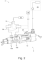
- the Fig. 2 shows the proposed minimum quantity lubrication system 3.
- it has the previously described atomizer unit 2.
- a coolant and/or lubricant source 29 is provided for supplying the injection valve 13 with coolant and/or lubricant 4.
- the coolant and/or lubricant 4 is here and preferably liquid.
- Such high pressures enable good distribution of the coolant and/or lubricant 4 when it is injected into the injection chamber 18.
- the minimum quantity lubrication system 3 has a compressed air source arrangement 30 for supplying the first and/or second supply channel 10, 15 with compressed air.
- a single source of compressed air is provided to supply both supply channels with compressed air.
- two separate compressed air sources can also form the compressed air source arrangement and a first compressed air source supplies the first supply channel with compressed air and a second compressed air source supplies the second supply channel with compressed air.
- the compressed air is generated here and preferably from ambient air.
- the minimum quantity lubrication system 3 of the exemplary embodiment has a compressed air source which provides the compressed air for the first compressed air stream 11 and the second compressed air stream 16.
- a booster 31 is provided here in the feed line for the first compressed air stream 11, which increases the pressure of the first compressed air stream by boosting compression.
- the first supply channel 10 is provided with compressed air at a higher pressure than the second supply channel 15.
- the pressure difference of the pressure provision is here and preferably from 2 to 8 bar, more preferably from 4 to 6 bar, more preferably substantially 5 bar.
- the first feed channel 10 is provided with compressed air with a built-up transport stream 17 at a pressure of 3 to 8 bar, more preferably 4 to 7 bar, in the exemplary embodiment of 6 bar, and / or the second feed channel 15 compressed air with a built-up transport stream 17 with a pressure of 8 to 15 bar, more preferably from 9 to 13 bar, here from 11 bar.
- the pressure of the first and second compressed air streams can be adjusted separately from one another.
- the proposed processing system 1 has a tool 5 and a minimum quantity lubrication system 1 with an atomizer unit 2.
- the processing system 1 has a spindle 32 with a tool holder 1a for holding the tool 5.
- the processing system 1 has an end effector 34 in which the spindle 32 is arranged.
- the compressed air source arrangement and/or the coolant and/or lubricant source 29 is arranged here and preferably away from the end effector 34.
- the processing system 1 is preferably a drilling machine, here a drilling/riveting machine.
- the tool 5 is a drill in the exemplary embodiment.
- the spindle 32 is here and preferably part of a drilling unit 33 of the end effector 34.
- the end effector 34 can have a riveting unit 35 for setting rivet elements in a hole drilled with the drilling unit 33.
- the processing system 1 has a control arrangement 26 for controlling the processing system 1 and the minimum quantity lubrication system 3 and thus the machining process.
- the control arrangement 26 has a processing system control and possibly a minimum quantity lubrication system control.
- the processing system control is preferably a PLC control. It controls the machining process.
- the minimum quantity lubrication system control receives coolant and/or lubricant parameters here and preferably from the processing system control.
- the minimum quantity lubrication system 3, in particular the atomizer unit 2 of the minimum quantity lubrication system 3 is controlled, in particular the addition of the coolant and/or lubricant 4 as well as the transport stream 17.
- the atomizer unit 2 is arranged here and preferably outside the spindle 32. This is particularly necessary for small and compact spindles 32. An arrangement of the atomizer unit 2 in the spindle 32 is usually not possible here due to the installation space.
- the continuation channel 12 runs here from the atomizer unit 2 through the spindle 32 and the tool 5 to the processing point 7.
- the atomizer unit 2 is arranged in front of the spindle 32 in the flow direction of the transport stream 17.
- the flow path W from the atomizer unit 2 to the spindle 32 is less than 50 cm, more preferably less than 20 cm, more preferably less than 10 cm. The closer the atomizer unit 2 is to the spindle 32, the shorter latency times for switching the aerosol on and off can be achieved.
- the spindle axis S intersects the injection valve 13 and/or the nozzle 22, more preferably that the spindle axis S is arranged coaxially with the central axis M E of the injection valve and/or with the central axis M D of the nozzle opening 23 of the nozzle 22.
- the spindle axis S and the central axis M E and / or the central axis M D can also not be arranged coaxially. They are then preferably designed parallel to one another or their intersection is preferably a maximum of 20 cm, more preferably a maximum of 10 cm, away from the atomizer unit.
- the transport stream 17 is built up before or during a machining process and the coolant and/or lubricant 4 is added to the built-up transport stream 17, forming an aerosol with the transport stream 17.
- the aerosol can then be transported to the processing point 7 in a particularly simple manner by the transport stream 17. Building up the transport stream 17 before injecting the coolant and/or lubricant enables very precise control of the addition of the coolant and/or lubricant as well as its transport to the processing point 7 and thus a very precise control of cooling or lubrication. This allows small amounts of coolant and/or lubricant 4 to be used at exactly the times when the coolant and/or lubricant 4 is actually needed or offers an advantage.
- the coolant and/or lubricant 4 is only added after a constant transport flow 17 has been formed. That is, when the transport stream 17 has become quasi-stationary. This makes it possible to determine very precisely the period of time after which the aerosol emerges from the at least one outlet opening 5a of the tool 5 after the injection valve 13 has been activated for injecting the coolant and/or lubricant 4.
- the coolant and/or lubricant 4 is added to the transport stream 17 in such a way that the aerosol only emerges from the at least one outlet opening 5a after the immersion, in particular complete immersion, of at least one outlet opening 5a of the tool 5a into the workpiece 6.
- the machining process in the exemplary embodiment Fig. 4 a drilling process, begins here and preferably with loading the machining parameters for the upcoming machining process (A2: Start machining process).
- the machining processing parameters can be, for example, the tool 5 to be used and/or the machining geometry, here for example the geometry data of the borehole, and/or a starting position and/or a tool feed and/or a spindle speed and/or workpiece parameters, such as workpiece material structure and/or workpiece geometry and /or workpiece orientation, and/or coolant and/or lubricant parameters.
- a cooling and/or lubrication process is started by means of the minimum quantity lubrication system 3 (B1: transfer of coolant and/or lubricant parameters). This is described in more detail below.
- the tool 5 is moved here and preferably to the starting position (A3: moving to the starting position).
- the starting position here and preferably means the position from which the tool 5 is approached for machining in a machining mode, cf. Fig. 5a ).
- the starting position is usually approached in rapid traverse, preferably with subsequent fine positioning.
- the processing system 1 is in a positioning mode.
- machining parameters for the machining process in particular the next position of the workpiece 6, are now activated.
- the spindle 32 is accelerated to the spindle speed and a feed travel profile for the tool 5 is activated (A4: activation of the machining parameters).
- machining in the machining process.
- drilling is carried out up to one layer end of the workpiece 6 (A5: drilling to the end of the layer).
- A6 End of layer reached?
- a query is made as to whether the workpiece 6 has another layer (A7: another layer). If it has another layer, the machining parameters are activated for this further layer and in this respect the system jumps back to activating the machining parameters (step A4).
- coolant and/or lubricant parameters can be transferred again, in particular to the minimum quantity lubrication system 3.
- the cooling and/or lubrication process is then adjusted accordingly. If the workpiece 6 has no further position, the cooling and/or lubrication process is ended according to a stop routine (B8 to B10).
- a fast travel i.e. another feed with increased feed speed
- the lowering is carried out with a lowering section 5b of the tool 5.
- the fast travel to the countersink entry triggers a countersink cooling and/or lubrication process (A9: fast travel to the countersink entry).
- the cooling and/or lubrication of the lowering operation takes place here and preferably by means of external minimal quantity lubrication.
- the minimum quantity lubrication system 3 has an external atomizer unit 36, which is arranged outside the spindle 32 and whose external continuation channel 37 leads past the spindle 32 to the processing point 7.
- the external atomizer unit 36 has the same features as the internal atomizer unit 6. Preferably they are structurally sound.
- Coolant and/or lubricant parameters for external minimum quantity lubrication can also be transferred (C: external minimum quantity lubrication).
- the cooling and/or lubrication process takes place as follows during the machining process.
- the cooling and/or lubricant process within the control arrangement 26 is preferably started by transferring at least one coolant and/or lubricant parameter (B1: transfer of coolant and/or lubricant parameters).
- An internal lubricant supply here and preferably means the minimum quantity lubrication system 3 with the atomizer unit 2, which supplies the processing point 7 with coolant and/or lubricant 4 through the tool 5 (B2: activation of the internal minimum quantity lubrication).
- settings are now made for the transport stream 17 and/or a first compressed air stream 11 and/or a second compressed air stream 16 (B3: setting of the transport stream). These settings are based here and preferably on the transferred coolant and/or lubricant parameters.
- control arrangement 26 sets up the transport stream 17 at a transport air control time, in particular by controlling a compressed air valve arrangement 38, based on a predefined event, the transport air event, the machining process or a predicted predefined future Event, the predicted transport air event, of the machining process. This allows the structure of the transport stream 17 to be controlled particularly well and precisely to meet the requirements of the machining process.
- the transport event or predicted transport event can be a predetermined temporal and/or geometric distance of the tool 5 to the workpiece 6 and/or the first contact of the tool 5 with the workpiece 6 and/or the imminent immersion of the at least one outlet opening of the tool 5 into the workpiece 6 and/or reaching a predetermined immersion depth of the outlet opening 5a of the tool 5 into the workpiece 6 and/or the complete immersion of the at least one outlet opening 5a of the tool 5 into the workpiece 6.
- the transport air event is the reaching of a predetermined time distance of the tool 5 to the workpiece 6 (B4: reaching the predetermined distance of the tool to the workpiece). This corresponds to the relative position of tool 5 and workpiece 6 in Fig. 5b ).
- the achievement of a time distance of 50 ms between the tool 5, here the drill tip, and the workpiece 6 is intended as a transport air event. This time distance can be easily determined due to the known feed rate.
- the transport stream is established (B5: Establishment of the transport stream).
- the build-up of the transport stream takes between 15 and 40 ms, preferably between 20 and 30 ms, here 25 ms.
- control arrangement 26 controls the injection valve 13 for adding the coolant and/or lubricant 4 to the transport stream 17 at an injection control time based on a predefined event, the injection event, the cutting Machining process or to a predicted predefined future event, the predicted injection event, of the machining process.
- the coolant and/or lubricant 4 can be transported to the machining point 7, particularly precisely tailored to the machining process and the position of the tool 5.
- the transport air control time is here before the injection control time.
- the transport air control time is at least between 10 and 500 ms, more preferably between 12 and 200 ms, more preferably between 15 and 100 ms, more preferably between 18 and 50 ms, here 25 ms, before the injection control time.
- the injection event or the predicted injection event can be a predetermined temporal and/or geometric distance of the tool 5 from the workpiece 6 and/or the first contact of the tool 5 with the workpiece 6 and/or the imminent immersion of the at least one outlet opening 5a of the tool 5 into the workpiece 6 and/or reaching a predetermined immersion depth of the outlet opening 5a of the tool 5 into the workpiece 6 and/or the complete immersion of the at least one outlet opening of the tool 5 into the workpiece 6.
- the injection event is the first contact of the tool 5, here the drill, with the workpiece 6, i.e. the impact of the drill tip on the workpiece 6 (B6: contact of the tool with the workpiece).
- B6 contact of the tool with the workpiece
- the injection valve 13 is activated to inject the coolant and/or lubricant 4 at this point in time and the coolant and/or lubricant is injected (B7: injection of the coolant and/or lubricant).
- the time between the activation of the injection valve 13 and the exit of the coolant and/or lubricant 4 is preferably a maximum of 15 ms, here a maximum of 10 ms.
- the events serve here, so to speak, as triggers or predicted triggers for the build-up of the transport flow 17 or the activation of the injection valve 13 to start injecting the cooling and/or lubricant 4.
- the injection event or the predicted injection event and the transport air event or the predicted transport air event are defined differently. However, both can also be defined the same, in which case a, in particular predefined, time offset between the transport air control time and the injection control time is provided.
- the coolant and/or lubricant 4 is preferably added to the transport stream 17 in such a way that the aerosol only emerges from the at least one outlet opening 5a after the immersion, in particular complete immersion, of at least one outlet opening 5a of the tool 5 into the workpiece 6.
- the addition takes place in such a way that the aerosol only emerges from the at least one outlet opening 5a after all outlet openings of the tool 5 have been completely immersed.
- a corresponding relative position is in the Fig. 5d ) shown.
- control event is tailored more specifically to the workpiece 6 or a relative position between the workpiece 6 and the tool 5.
- a latency time between the activation of the injection valve 13 and the exit of the aerosol from an outlet opening 5a of the tool 5 can be determined. For example, this can be measured and preferably stored in the control arrangement 26. However, this can also be determined, in particular calculated, by the control arrangement 26, for example.
- control arrangement 26 determines the latency based on a processing plant-specific value and a tool-specific value and, if necessary, a coolant- and/or lubricant-specific value.
- the latency time is preferably less than or equal to 50 ms, preferably less than or equal to 40 ms, more preferably less than or equal to 30 ms.
- the coolant and/or lubricant 4 To add the coolant and/or lubricant 4, its exit from the injection valve 13 is controlled. With or after the coolant and/or lubricant 4 emerges from the injection valve 13, the coolant and/or lubricant 4 is atomized. This is done here and preferably by means of a nozzle 2. This is preferably arranged downstream, in particular separately, from the injection valve 13 in the atomizer unit 2. The coolant and/or lubricant 4 can previously be partially atomized by the injection valve 13 as it exits the same.
- the aerosol is created by injecting the coolant and/or lubricant 4 into a first compressed air stream 11, in particular by means of the injection valve 13 and preferably by atomizing the compressed air mixture of the injected coolant and/or lubricant 4 and the first Compressed air flow 11, in particular through the nozzle 22, is generated.
- the first compressed air stream 11 and the second compressed air stream 16 then form the transport stream 17 here and preferably, if necessary with the injected and/or atomized coolant and/or lubricant 4.
- the coolant and/or lubricant 4 is added to the built-up transport stream 17 in pulses, in particular by means of the injection valve 13 and optionally the nozzle 22, to form the aerosol.
- the opening duration of the injection valve 13 is here and preferably shorter than the duration between two openings of the injection valve 13.
- the injection valve 13 is preferably operated with a control frequency of 5 up to 100 Hz, preferably 10 to 50 Hz, here 35 Hz.
- the opening duration of the injection valve 13 is preferably less than 10 ms, more preferably less than 2 ms, more preferably less than 1 ms, more preferably less than 0.5 ms, more preferably less than 0.4 ms, in the exemplary embodiment 0.37 ms.
- an operator can adjust and/or parameterize the minimum quantity lubrication system 3 for a workpiece 6, in particular for each position of the workpiece 6, in the machining process.
- the cooling and/or lubrication can be adjusted for different layers, in particular each layer, of the workpiece 6.
- the setting and/or parameterization takes place here and preferably before the start of the machining process.
- a layer of a workpiece 6 can be formed by a workpiece part 6a, 6b.
- the minimum quantity lubrication system 3 can be set and/or parameterized for each workpiece part 6a, 6b.
- a workpiece 6, in particular a workpiece part 6a, 6b can consist of several layers. This can be, for example, a hybrid workpiece constructed in layers. Then each layer of the workpiece 6 or workpiece part 6a, 6b can form a layer of the workpiece 6.
- the transport stream 17, in particular the pressure of the first compressed air stream 11 and/or the second compressed air stream 16, and the amount of coolant and/or lubricant used can be adjusted and/or parameterized, in particular by the operator.
- the setting and/or parameterization takes place here and preferably before the start of the machining process.
- the pressure of the second compressed air stream 16 is parameterized by the operator and the control arrangement 26, in particular the minimum quantity lubrication system control, sets the first and second compressed air streams 11, 16 based on the parameterization of the second compressed air stream 16.
- the operator can parameterize the amount of lubricant.
- control arrangement 26 in particular the minimum quantity lubrication system control, adjusts the pressure of the coolant and/or lubricant 4 and/or the control of the injection valve 13 based on the parameterization of the quantity of lubricant.
- the control of the injection valve 13 is adjusted here and preferably by determining the control frequency and/or the opening duration and/or a transient which describes a flutter status of the valve.
- the cooling and/or lubrication is preferably set differently for a first layer of the workpiece 6 than for a second layer of the workpiece 6. Additionally or alternatively, the addition of coolant and/or lubricant 4 for individual layers of the workpiece 6 can be switched off be, especially if these layers are made of fiber composite material, in particular a carbon fiber reinforced plastic (CFRP).
- CFRP carbon fiber reinforced plastic
- the control arrangement 26 preferably provides different opening times for the injection valve 13 depending on the viscosity of the coolant and/or lubricant currently being used.
- the addition of the coolant and/or lubricant 4 to the transport stream 17 is first stopped and then the transport stream 17 is stopped.
- the addition of the coolant and/or lubricant 4 stops when the tool 5 begins to emerge from the workpiece 6 and/or the tool 5, here the drill head, is completely penetrated through the workpiece 6 and/or when a predetermined relative position is reached Tool 5 to workpiece 6.
- the addition of coolant and/or lubricant 4 is stopped and preferably when a layer end, in particular the last layer end, of the workpiece 6 is reached (B8: stopping the injection). This relative position of tool 5 and workpiece 6 is in the Fig. 5e ) shown.
- the transport stream 17 is only stopped after a, in particular predetermined, time (B9: wait for the predetermined time; B10: stop the transport stream). In this way, the aerosol that is still in the continuation channel 12 can still be largely transported out of it.
- the time is from stopping the addition of the coolant and/or lubricant 4 to the transport stream 17 and stopping the transport stream 17 preferably between 50 and 500 ms, more preferably between 200 and 300 ms, here 250 ms.
- the machining process is a drilling process for a first borehole.
- a further drilling process can be carried out for a second borehole, in particular on the same workpiece 6.
- the transport stream 17 is canceled and restarted, with the transport stream being built up before or during the second drilling process as a further machining process and the transport stream 17 built up at least in the injection area 14 through the injection valve 13, the cooling and/or or lubricant 4, with the transport stream 17 forming an aerosol, is added.
- a rivet element is placed by the processing system 1 into the first borehole between the two drilling processes. Switching off can save energy. In addition, it is avoided that coolant and/or lubricant residues adhering in the extension channel 12 are blown out during the setting of the rivet element.
Landscapes
- Engineering & Computer Science (AREA)
- General Engineering & Computer Science (AREA)
- Mechanical Engineering (AREA)
- Chemical & Material Sciences (AREA)
- Combustion & Propulsion (AREA)
- Oil, Petroleum & Natural Gas (AREA)
- Physics & Mathematics (AREA)
- Fluid Mechanics (AREA)
- Auxiliary Devices For Machine Tools (AREA)
- Drilling And Boring (AREA)
Applications Claiming Priority (2)
| Application Number | Priority Date | Filing Date | Title |
|---|---|---|---|
| DE102018111083.9A DE102018111083A1 (de) | 2018-05-08 | 2018-05-08 | Zerstäubereinheit eines Minimalmengenschmiersystems |
| PCT/EP2019/061822 WO2019215232A1 (de) | 2018-05-08 | 2019-05-08 | Zerstäubereinheit eines minimalmengenschmiersystems |
Publications (2)
| Publication Number | Publication Date |
|---|---|
| EP3790705A1 EP3790705A1 (de) | 2021-03-17 |
| EP3790705B1 true EP3790705B1 (de) | 2023-11-08 |
Family
ID=66448575
Family Applications (1)
| Application Number | Title | Priority Date | Filing Date |
|---|---|---|---|
| EP19722894.3A Active EP3790705B1 (de) | 2018-05-08 | 2019-05-08 | Zerstäubereinheit eines minimalmengenschmiersystems |
Country Status (6)
| Country | Link |
|---|---|
| US (1) | US12072061B2 (es) |
| EP (1) | EP3790705B1 (es) |
| CN (1) | CN112292232B (es) |
| DE (1) | DE102018111083A1 (es) |
| ES (1) | ES2969905T3 (es) |
| WO (1) | WO2019215232A1 (es) |
Families Citing this family (8)
| Publication number | Priority date | Publication date | Assignee | Title |
|---|---|---|---|---|
| DE102018111083A1 (de) | 2018-05-08 | 2019-11-14 | Broetje-Automation Gmbh | Zerstäubereinheit eines Minimalmengenschmiersystems |
| DE102019130112A1 (de) * | 2019-11-07 | 2021-05-12 | Broetje-Automation Gmbh | Zerstäubereinheit |
| CN111547476A (zh) * | 2020-06-12 | 2020-08-18 | 厦门烟草工业有限责任公司 | 链板输送机的链轮润滑装置、方法、链板输送机和烟草储存设备 |
| CN112605709B (zh) * | 2020-12-22 | 2022-11-04 | 青岛理工大学 | 一种航空铝合金微量润滑铣削加工装置 |
| CN113107848B (zh) * | 2021-04-25 | 2023-03-03 | 金华电力设计院有限公司 | 一种基于空压机组的动力装置 |
| US20240189956A1 (en) * | 2022-12-12 | 2024-06-13 | Ford Global Technologies, Llc | Machining system with flow restrictor for supercritical carbon dioxide-based minimum quantity lubrication machining |
| WO2025109595A1 (en) * | 2023-11-20 | 2025-05-30 | Smartec Ltd Israel | Gas and liquid coolant (glc) aeroforce for general machining applications |
| CN120394222A (zh) * | 2024-01-30 | 2025-08-01 | 贝思德迩医疗器材(广州)有限公司 | 牙科手机注油机 |
Citations (1)
| Publication number | Priority date | Publication date | Assignee | Title |
|---|---|---|---|---|
| EP0535271B1 (de) * | 1991-10-01 | 1995-05-31 | Edmar Link | Kühlschmiervorrichtung |
Family Cites Families (38)
| Publication number | Priority date | Publication date | Assignee | Title |
|---|---|---|---|---|
| US2113506A (en) * | 1937-01-09 | 1938-04-05 | Bert E Clough | Lubricant atomizer |
| US2969748A (en) * | 1959-02-12 | 1961-01-31 | F E Myers & Bro Co | Ejector |
| US3561680A (en) * | 1968-09-16 | 1971-02-09 | Respond Inc | Spray head assembly |
| US3696889A (en) * | 1970-08-31 | 1972-10-10 | Scovill Manufacturing Co | Air line lubricator |
| US4597526A (en) * | 1980-05-13 | 1986-07-01 | Lonza Ltd. | Process and apparatus for the superfine spraying of suspensions |
| US4527661A (en) * | 1981-10-29 | 1985-07-09 | Kearney & Trecker Corporation | Adaptive control system for machine tool or the like |
| DE3743968C1 (de) * | 1987-12-23 | 1988-12-29 | Edmar Link | Kuehlschmiervorrichtung |
| US5725071A (en) * | 1997-01-28 | 1998-03-10 | Master Pneumatic-Detroit, Inc. | Machine cutting tool selective lubricator with air blow-off |
| DE19721650C2 (de) * | 1997-05-23 | 2003-05-22 | Vogel Willi Ag | Vorrichtung zur Aerosolerzeugung |
| DE29724651U1 (de) | 1997-05-23 | 2002-08-14 | Willy Vogel AG, 12277 Berlin | Vorrichtung zur Aerosolerzeugung |
| US6659370B1 (en) * | 1998-05-25 | 2003-12-09 | Fuji Bc Engineering Co., Ltd. | Liquid spray device and cutting method |
| DE19829769C2 (de) * | 1998-07-03 | 2000-05-18 | Mann & Hummel Filter | Mischvorrichtung zum Einbringen eines Fluides in ein strömendes, anderes Fluid |
| DE19915265A1 (de) * | 1999-04-03 | 2000-06-29 | Daimler Chrysler Ag | Verfahren und Vorrichtung zur Minimalmengen-Kühlschmierung bei Zerspannprozessen |
| JP3549194B2 (ja) * | 2000-02-22 | 2004-08-04 | 日本スピードショア株式会社 | 工作加工方法およびそれに用いる霧状体供給装置 |
| DE10222863C1 (de) * | 2002-05-23 | 2003-11-20 | Edmar Link | Minimalmengen-Kühlschmiervorrichtung |
| AU2003291973A1 (en) * | 2002-12-20 | 2004-07-14 | Lifecycle Pharma A/S | A self-cleaning spray nozzle |
| DE10310118A1 (de) * | 2003-03-06 | 2004-09-16 | Willy Vogel Ag | Schmiervorrichtung mit Einspritzeinrichtung und Schmierverfahren |
| DE10349642A1 (de) * | 2003-10-21 | 2005-05-19 | Bielomatik Leuze Gmbh + Co Kg | Vorrichtung zur Aerosolerzeugung und Injektoreinheit |
| DE102004034689A1 (de) * | 2004-01-13 | 2005-08-04 | Gunther Neumann | Minimalmengenschmier-Verfahren und -Vorrichtung |
| JP3966418B2 (ja) * | 2004-10-01 | 2007-08-29 | 大同メタル工業株式会社 | オイルミスト生成装置 |
| DE102007008227A1 (de) * | 2007-02-20 | 2008-08-21 | Edmar Link | Minimalmengen-Kühlschmiervorrichtung |
| CN201069038Y (zh) * | 2007-05-29 | 2008-06-04 | 暹嵘机械有限公司 | 油气混合喷雾装置 |
| CN101224491B (zh) * | 2008-01-25 | 2011-04-20 | 陈华 | 可实现不停机在线自动清洗的喷雾冷却系统 |
| DE102008013540A1 (de) * | 2008-03-11 | 2009-09-24 | Microjet Gmbh | Vorrichtung zum Erzeugen und Versprühen eines Aerosols |
| US8048830B1 (en) * | 2008-06-19 | 2011-11-01 | Cool Clean Technologies, Inc. | Method of forming and using carbonated machining fluid |
| DE202009017656U1 (de) | 2009-12-28 | 2011-05-12 | Aygün, Hakki | Hochdruck-Minimalmengen-Schmiersystem |
| DE102010028241A1 (de) * | 2010-04-27 | 2011-10-27 | Robert Bosch Gmbh | Minimalmengenschmiersystem |
| WO2012000049A1 (en) * | 2010-06-30 | 2012-01-05 | Commonwealth Scientific And Industrial Research Organisation | Droplet generation system and method |
| CA2784109C (en) * | 2012-07-27 | 2019-06-18 | Nex Flow Air Products Corp. | Apparatus and method for cooling and lubrication |
| CN203292942U (zh) | 2013-06-19 | 2013-11-20 | 杨伦 | 低温雾化冷风机 |
| AU2015203208B2 (en) * | 2014-06-20 | 2017-04-13 | Deere & Company | Hybrid flow nozzle and control system |
| DE102015213536B3 (de) * | 2015-07-17 | 2016-11-10 | MAPAL Fabrik für Präzisionswerkzeuge Dr. Kress KG | Übertragungselement und Werkzeugelement |
| CN108348933B (zh) * | 2015-08-28 | 2022-01-28 | 明尼苏达州大学董事会 | 喷嘴和混合流体流的方法 |
| EP3436114B1 (en) * | 2016-03-31 | 2023-08-02 | Philip Morris Products S.A. | Atomizing assembly for use in an aerosol-generating system |
| US9573147B1 (en) * | 2016-04-15 | 2017-02-21 | Kaer Biotherapeutics Corporation | Aerosolizing nozzle and method of operating such aerosolizing nozzle |
| DE102016115039A1 (de) | 2016-08-12 | 2018-03-01 | Franz Haimer Maschinenbau Kg | Werkzeugaufnahme |
| DE102018111083A1 (de) | 2018-05-08 | 2019-11-14 | Broetje-Automation Gmbh | Zerstäubereinheit eines Minimalmengenschmiersystems |
| DE102019130112A1 (de) * | 2019-11-07 | 2021-05-12 | Broetje-Automation Gmbh | Zerstäubereinheit |
-
2018
- 2018-05-08 DE DE102018111083.9A patent/DE102018111083A1/de active Pending
-
2019
- 2019-05-08 ES ES19722894T patent/ES2969905T3/es active Active
- 2019-05-08 WO PCT/EP2019/061822 patent/WO2019215232A1/de not_active Ceased
- 2019-05-08 US US17/053,142 patent/US12072061B2/en active Active
- 2019-05-08 EP EP19722894.3A patent/EP3790705B1/de active Active
- 2019-05-08 CN CN201980030965.6A patent/CN112292232B/zh active Active
Patent Citations (1)
| Publication number | Priority date | Publication date | Assignee | Title |
|---|---|---|---|---|
| EP0535271B1 (de) * | 1991-10-01 | 1995-05-31 | Edmar Link | Kühlschmiervorrichtung |
Also Published As
| Publication number | Publication date |
|---|---|
| US12072061B2 (en) | 2024-08-27 |
| ES2969905T3 (es) | 2024-05-23 |
| US20210239267A1 (en) | 2021-08-05 |
| DE102018111083A1 (de) | 2019-11-14 |
| CN112292232B (zh) | 2023-01-13 |
| CN112292232A (zh) | 2021-01-29 |
| EP3790705A1 (de) | 2021-03-17 |
| WO2019215232A1 (de) | 2019-11-14 |
Similar Documents
| Publication | Publication Date | Title |
|---|---|---|
| EP3790705A1 (de) | Zerstäubereinheit eines minimalmengenschmiersystems | |
| EP4054795B1 (de) | Zerstäubereinheit | |
| DE102007053350B4 (de) | Verfahren zur spanabhebenden Bearbeitung von Werkstücken | |
| DE60116880T2 (de) | Spindelvorrichtung für werkzeugmaschine | |
| EP2219813B1 (de) | Aerostatisches lager und verfahren zu dessen herstellung | |
| DE10104012C2 (de) | Vorrichtung zur Aerosolerzeugung | |
| DE69203839T2 (de) | Funkenerosionbohrvorrichtung. | |
| DE60113414T2 (de) | Automatische schneidflüssigkeitszuführvorrichtung | |
| CH689157A5 (de) | Verfahren und Vorrichtung zur Bildung einer Modifikationsschicht durch elektroerosive Bearbeitung. | |
| DE112016006887B4 (de) | Drahterodiermaschine, Führungsbaugruppe und Drahterodierverfahren | |
| EP2730358B1 (de) | Verfahren zum Bohren | |
| EP0206041A2 (de) | Verfahren zum wiederholten, automatischen Einziehen der Drahtelektrode einer Drahterosionsmaschine und Vorrichtung zur Durchführung des Verfahrens | |
| DE2259419A1 (de) | Verfahren und einrichtung zum elektrochemischen herstellen kleiner loecher mittels kontrollierten stromes | |
| DE10064232C1 (de) | Vorrichtung und Verfahren zum Führen einer Bearbeitungselektrode in einer Werkzeugmaschine, insbesondere in einer Drahterodiermaschine | |
| EP3013508B1 (de) | Verfahren zur maschinellen bearbeitung, insbesondere zur maschinellen schweissbearbeitung und steuervorrichtung für eine einstelleinrichtung einer prozessgaszufuhr | |
| DE102018111082A1 (de) | Verfahren zum Betreiben einer Bearbeitungsanlage | |
| DE202008003538U1 (de) | Bohreinrichtung zur Herstellung einer Präzisions-Durchgangsbohrung | |
| EP3865249A1 (de) | Verfahren zur kühlung und schmierung von zerspanprozessen | |
| DE202013103529U1 (de) | Vorrichtung zur Aerosolerzeugung | |
| DE102015206567A1 (de) | Langdrehautomat mit zwei NC-gesteuerten Bearbeitungsachsen und Verfahren zum Bearbeiten von Werkstücken auf einem Langdrehautomat mit zwei NC gesteuerten Bearbeitungsachsen | |
| DE102016110541B4 (de) | Werkzeugmaschine mit einer Steuerung | |
| EP1663572A1 (de) | Vorrichtung und verfahren zur aerosolschmierung unter verwendung eines bypass-ventils | |
| EP1054738B1 (de) | Nebelgeneratorkopf | |
| DE102014106106A1 (de) | Beschichtungsvorrichtung und Verfahren zum Beschichten einer Werkstückfläche | |
| DE102020121951B4 (de) | Vorrichtung und Verfahren zur Herstellung von Werkstücken |
Legal Events
| Date | Code | Title | Description |
|---|---|---|---|
| STAA | Information on the status of an ep patent application or granted ep patent |
Free format text: STATUS: UNKNOWN |
|
| STAA | Information on the status of an ep patent application or granted ep patent |
Free format text: STATUS: THE INTERNATIONAL PUBLICATION HAS BEEN MADE |
|
| PUAI | Public reference made under article 153(3) epc to a published international application that has entered the european phase |
Free format text: ORIGINAL CODE: 0009012 |
|
| STAA | Information on the status of an ep patent application or granted ep patent |
Free format text: STATUS: REQUEST FOR EXAMINATION WAS MADE |
|
| 17P | Request for examination filed |
Effective date: 20201013 |
|
| AK | Designated contracting states |
Kind code of ref document: A1 Designated state(s): AL AT BE BG CH CY CZ DE DK EE ES FI FR GB GR HR HU IE IS IT LI LT LU LV MC MK MT NL NO PL PT RO RS SE SI SK SM TR |
|
| AX | Request for extension of the european patent |
Extension state: BA ME |
|
| RIN1 | Information on inventor provided before grant (corrected) |
Inventor name: JOSTMANN, SEBASTIAN Inventor name: LEHMANN, MARC Inventor name: FRERS, HENNING |
|
| DAV | Request for validation of the european patent (deleted) | ||
| DAX | Request for extension of the european patent (deleted) | ||
| GRAP | Despatch of communication of intention to grant a patent |
Free format text: ORIGINAL CODE: EPIDOSNIGR1 |
|
| STAA | Information on the status of an ep patent application or granted ep patent |
Free format text: STATUS: GRANT OF PATENT IS INTENDED |
|
| INTG | Intention to grant announced |
Effective date: 20230222 |
|
| GRAJ | Information related to disapproval of communication of intention to grant by the applicant or resumption of examination proceedings by the epo deleted |
Free format text: ORIGINAL CODE: EPIDOSDIGR1 |
|
| STAA | Information on the status of an ep patent application or granted ep patent |
Free format text: STATUS: REQUEST FOR EXAMINATION WAS MADE |
|
| GRAP | Despatch of communication of intention to grant a patent |
Free format text: ORIGINAL CODE: EPIDOSNIGR1 |
|
| STAA | Information on the status of an ep patent application or granted ep patent |
Free format text: STATUS: GRANT OF PATENT IS INTENDED |
|
| INTC | Intention to grant announced (deleted) | ||
| INTG | Intention to grant announced |
Effective date: 20230728 |
|
| GRAS | Grant fee paid |
Free format text: ORIGINAL CODE: EPIDOSNIGR3 |
|
| GRAA | (expected) grant |
Free format text: ORIGINAL CODE: 0009210 |
|
| STAA | Information on the status of an ep patent application or granted ep patent |
Free format text: STATUS: THE PATENT HAS BEEN GRANTED |
|
| AK | Designated contracting states |
Kind code of ref document: B1 Designated state(s): AL AT BE BG CH CY CZ DE DK EE ES FI FR GB GR HR HU IE IS IT LI LT LU LV MC MK MT NL NO PL PT RO RS SE SI SK SM TR |
|
| REG | Reference to a national code |
Ref country code: GB Ref legal event code: FG4D Free format text: NOT ENGLISH |
|
| REG | Reference to a national code |
Ref country code: CH Ref legal event code: EP |
|
| REG | Reference to a national code |
Ref country code: DE Ref legal event code: R096 Ref document number: 502019009874 Country of ref document: DE |
|
| REG | Reference to a national code |
Ref country code: IE Ref legal event code: FG4D Free format text: LANGUAGE OF EP DOCUMENT: GERMAN |
|
| REG | Reference to a national code |
Ref country code: LT Ref legal event code: MG9D |
|
| REG | Reference to a national code |
Ref country code: NL Ref legal event code: MP Effective date: 20231108 |
|
| PG25 | Lapsed in a contracting state [announced via postgrant information from national office to epo] |
Ref country code: GR Free format text: LAPSE BECAUSE OF FAILURE TO SUBMIT A TRANSLATION OF THE DESCRIPTION OR TO PAY THE FEE WITHIN THE PRESCRIBED TIME-LIMIT Effective date: 20240209 |
|
| PG25 | Lapsed in a contracting state [announced via postgrant information from national office to epo] |
Ref country code: IS Free format text: LAPSE BECAUSE OF FAILURE TO SUBMIT A TRANSLATION OF THE DESCRIPTION OR TO PAY THE FEE WITHIN THE PRESCRIBED TIME-LIMIT Effective date: 20240308 |
|
| PG25 | Lapsed in a contracting state [announced via postgrant information from national office to epo] |
Ref country code: LT Free format text: LAPSE BECAUSE OF FAILURE TO SUBMIT A TRANSLATION OF THE DESCRIPTION OR TO PAY THE FEE WITHIN THE PRESCRIBED TIME-LIMIT Effective date: 20231108 |
|
| PG25 | Lapsed in a contracting state [announced via postgrant information from national office to epo] |
Ref country code: NL Free format text: LAPSE BECAUSE OF FAILURE TO SUBMIT A TRANSLATION OF THE DESCRIPTION OR TO PAY THE FEE WITHIN THE PRESCRIBED TIME-LIMIT Effective date: 20231108 |
|
| PG25 | Lapsed in a contracting state [announced via postgrant information from national office to epo] |
Ref country code: NL Free format text: LAPSE BECAUSE OF FAILURE TO SUBMIT A TRANSLATION OF THE DESCRIPTION OR TO PAY THE FEE WITHIN THE PRESCRIBED TIME-LIMIT Effective date: 20231108 Ref country code: LT Free format text: LAPSE BECAUSE OF FAILURE TO SUBMIT A TRANSLATION OF THE DESCRIPTION OR TO PAY THE FEE WITHIN THE PRESCRIBED TIME-LIMIT Effective date: 20231108 Ref country code: IS Free format text: LAPSE BECAUSE OF FAILURE TO SUBMIT A TRANSLATION OF THE DESCRIPTION OR TO PAY THE FEE WITHIN THE PRESCRIBED TIME-LIMIT Effective date: 20240308 Ref country code: GR Free format text: LAPSE BECAUSE OF FAILURE TO SUBMIT A TRANSLATION OF THE DESCRIPTION OR TO PAY THE FEE WITHIN THE PRESCRIBED TIME-LIMIT Effective date: 20240209 Ref country code: BG Free format text: LAPSE BECAUSE OF FAILURE TO SUBMIT A TRANSLATION OF THE DESCRIPTION OR TO PAY THE FEE WITHIN THE PRESCRIBED TIME-LIMIT Effective date: 20240208 Ref country code: PT Free format text: LAPSE BECAUSE OF FAILURE TO SUBMIT A TRANSLATION OF THE DESCRIPTION OR TO PAY THE FEE WITHIN THE PRESCRIBED TIME-LIMIT Effective date: 20240308 |
|
| REG | Reference to a national code |
Ref country code: ES Ref legal event code: FG2A Ref document number: 2969905 Country of ref document: ES Kind code of ref document: T3 Effective date: 20240523 |
|
| PG25 | Lapsed in a contracting state [announced via postgrant information from national office to epo] |
Ref country code: SE Free format text: LAPSE BECAUSE OF FAILURE TO SUBMIT A TRANSLATION OF THE DESCRIPTION OR TO PAY THE FEE WITHIN THE PRESCRIBED TIME-LIMIT Effective date: 20231108 Ref country code: RS Free format text: LAPSE BECAUSE OF FAILURE TO SUBMIT A TRANSLATION OF THE DESCRIPTION OR TO PAY THE FEE WITHIN THE PRESCRIBED TIME-LIMIT Effective date: 20231108 Ref country code: PL Free format text: LAPSE BECAUSE OF FAILURE TO SUBMIT A TRANSLATION OF THE DESCRIPTION OR TO PAY THE FEE WITHIN THE PRESCRIBED TIME-LIMIT Effective date: 20231108 Ref country code: NO Free format text: LAPSE BECAUSE OF FAILURE TO SUBMIT A TRANSLATION OF THE DESCRIPTION OR TO PAY THE FEE WITHIN THE PRESCRIBED TIME-LIMIT Effective date: 20240208 Ref country code: LV Free format text: LAPSE BECAUSE OF FAILURE TO SUBMIT A TRANSLATION OF THE DESCRIPTION OR TO PAY THE FEE WITHIN THE PRESCRIBED TIME-LIMIT Effective date: 20231108 Ref country code: HR Free format text: LAPSE BECAUSE OF FAILURE TO SUBMIT A TRANSLATION OF THE DESCRIPTION OR TO PAY THE FEE WITHIN THE PRESCRIBED TIME-LIMIT Effective date: 20231108 |
|
| PG25 | Lapsed in a contracting state [announced via postgrant information from national office to epo] |
Ref country code: DK Free format text: LAPSE BECAUSE OF FAILURE TO SUBMIT A TRANSLATION OF THE DESCRIPTION OR TO PAY THE FEE WITHIN THE PRESCRIBED TIME-LIMIT Effective date: 20231108 |
|
| PG25 | Lapsed in a contracting state [announced via postgrant information from national office to epo] |
Ref country code: CZ Free format text: LAPSE BECAUSE OF FAILURE TO SUBMIT A TRANSLATION OF THE DESCRIPTION OR TO PAY THE FEE WITHIN THE PRESCRIBED TIME-LIMIT Effective date: 20231108 |
|
| PG25 | Lapsed in a contracting state [announced via postgrant information from national office to epo] |
Ref country code: SK Free format text: LAPSE BECAUSE OF FAILURE TO SUBMIT A TRANSLATION OF THE DESCRIPTION OR TO PAY THE FEE WITHIN THE PRESCRIBED TIME-LIMIT Effective date: 20231108 |
|
| PG25 | Lapsed in a contracting state [announced via postgrant information from national office to epo] |
Ref country code: SM Free format text: LAPSE BECAUSE OF FAILURE TO SUBMIT A TRANSLATION OF THE DESCRIPTION OR TO PAY THE FEE WITHIN THE PRESCRIBED TIME-LIMIT Effective date: 20231108 Ref country code: SK Free format text: LAPSE BECAUSE OF FAILURE TO SUBMIT A TRANSLATION OF THE DESCRIPTION OR TO PAY THE FEE WITHIN THE PRESCRIBED TIME-LIMIT Effective date: 20231108 Ref country code: RO Free format text: LAPSE BECAUSE OF FAILURE TO SUBMIT A TRANSLATION OF THE DESCRIPTION OR TO PAY THE FEE WITHIN THE PRESCRIBED TIME-LIMIT Effective date: 20231108 Ref country code: EE Free format text: LAPSE BECAUSE OF FAILURE TO SUBMIT A TRANSLATION OF THE DESCRIPTION OR TO PAY THE FEE WITHIN THE PRESCRIBED TIME-LIMIT Effective date: 20231108 Ref country code: DK Free format text: LAPSE BECAUSE OF FAILURE TO SUBMIT A TRANSLATION OF THE DESCRIPTION OR TO PAY THE FEE WITHIN THE PRESCRIBED TIME-LIMIT Effective date: 20231108 Ref country code: CZ Free format text: LAPSE BECAUSE OF FAILURE TO SUBMIT A TRANSLATION OF THE DESCRIPTION OR TO PAY THE FEE WITHIN THE PRESCRIBED TIME-LIMIT Effective date: 20231108 |
|
| REG | Reference to a national code |
Ref country code: DE Ref legal event code: R097 Ref document number: 502019009874 Country of ref document: DE |
|
| PLBE | No opposition filed within time limit |
Free format text: ORIGINAL CODE: 0009261 |
|
| STAA | Information on the status of an ep patent application or granted ep patent |
Free format text: STATUS: NO OPPOSITION FILED WITHIN TIME LIMIT |
|
| 26N | No opposition filed |
Effective date: 20240809 |
|
| PG25 | Lapsed in a contracting state [announced via postgrant information from national office to epo] |
Ref country code: SI Free format text: LAPSE BECAUSE OF FAILURE TO SUBMIT A TRANSLATION OF THE DESCRIPTION OR TO PAY THE FEE WITHIN THE PRESCRIBED TIME-LIMIT Effective date: 20231108 |
|
| PG25 | Lapsed in a contracting state [announced via postgrant information from national office to epo] |
Ref country code: SI Free format text: LAPSE BECAUSE OF FAILURE TO SUBMIT A TRANSLATION OF THE DESCRIPTION OR TO PAY THE FEE WITHIN THE PRESCRIBED TIME-LIMIT Effective date: 20231108 |
|
| REG | Reference to a national code |
Ref country code: CH Ref legal event code: PL |
|
| PG25 | Lapsed in a contracting state [announced via postgrant information from national office to epo] |
Ref country code: MC Free format text: LAPSE BECAUSE OF FAILURE TO SUBMIT A TRANSLATION OF THE DESCRIPTION OR TO PAY THE FEE WITHIN THE PRESCRIBED TIME-LIMIT Effective date: 20231108 |
|
| PG25 | Lapsed in a contracting state [announced via postgrant information from national office to epo] |
Ref country code: LU Free format text: LAPSE BECAUSE OF NON-PAYMENT OF DUE FEES Effective date: 20240508 |
|
| PG25 | Lapsed in a contracting state [announced via postgrant information from national office to epo] |
Ref country code: MC Free format text: LAPSE BECAUSE OF FAILURE TO SUBMIT A TRANSLATION OF THE DESCRIPTION OR TO PAY THE FEE WITHIN THE PRESCRIBED TIME-LIMIT Effective date: 20231108 Ref country code: LU Free format text: LAPSE BECAUSE OF NON-PAYMENT OF DUE FEES Effective date: 20240508 Ref country code: CH Free format text: LAPSE BECAUSE OF NON-PAYMENT OF DUE FEES Effective date: 20240531 |
|
| REG | Reference to a national code |
Ref country code: BE Ref legal event code: MM Effective date: 20240531 |
|
| PG25 | Lapsed in a contracting state [announced via postgrant information from national office to epo] |
Ref country code: IE Free format text: LAPSE BECAUSE OF NON-PAYMENT OF DUE FEES Effective date: 20240508 |
|
| PG25 | Lapsed in a contracting state [announced via postgrant information from national office to epo] |
Ref country code: BE Free format text: LAPSE BECAUSE OF NON-PAYMENT OF DUE FEES Effective date: 20240531 |
|
| PGFP | Annual fee paid to national office [announced via postgrant information from national office to epo] |
Ref country code: DE Payment date: 20250527 Year of fee payment: 7 |
|
| PGFP | Annual fee paid to national office [announced via postgrant information from national office to epo] |
Ref country code: GB Payment date: 20250527 Year of fee payment: 7 |
|
| PGFP | Annual fee paid to national office [announced via postgrant information from national office to epo] |
Ref country code: IT Payment date: 20250527 Year of fee payment: 7 |
|
| REG | Reference to a national code |
Ref country code: AT Ref legal event code: MM01 Ref document number: 1629205 Country of ref document: AT Kind code of ref document: T Effective date: 20240508 |
|
| PGFP | Annual fee paid to national office [announced via postgrant information from national office to epo] |
Ref country code: FR Payment date: 20250528 Year of fee payment: 7 |
|
| PG25 | Lapsed in a contracting state [announced via postgrant information from national office to epo] |
Ref country code: AT Free format text: LAPSE BECAUSE OF NON-PAYMENT OF DUE FEES Effective date: 20240508 |
|
| PGFP | Annual fee paid to national office [announced via postgrant information from national office to epo] |
Ref country code: TR Payment date: 20250429 Year of fee payment: 7 |
|
| PG25 | Lapsed in a contracting state [announced via postgrant information from national office to epo] |
Ref country code: CY Free format text: LAPSE BECAUSE OF FAILURE TO SUBMIT A TRANSLATION OF THE DESCRIPTION OR TO PAY THE FEE WITHIN THE PRESCRIBED TIME-LIMIT; INVALID AB INITIO Effective date: 20190508 |
|
| PG25 | Lapsed in a contracting state [announced via postgrant information from national office to epo] |
Ref country code: HU Free format text: LAPSE BECAUSE OF FAILURE TO SUBMIT A TRANSLATION OF THE DESCRIPTION OR TO PAY THE FEE WITHIN THE PRESCRIBED TIME-LIMIT; INVALID AB INITIO Effective date: 20190508 |
|
| PG25 | Lapsed in a contracting state [announced via postgrant information from national office to epo] |
Ref country code: FI Free format text: LAPSE BECAUSE OF FAILURE TO SUBMIT A TRANSLATION OF THE DESCRIPTION OR TO PAY THE FEE WITHIN THE PRESCRIBED TIME-LIMIT Effective date: 20231108 |
|
| PGFP | Annual fee paid to national office [announced via postgrant information from national office to epo] |
Ref country code: ES Payment date: 20250630 Year of fee payment: 7 |