EP3790623B1 - Verbinderanordnung für ein system zur elektrischen stimulation - Google Patents
Verbinderanordnung für ein system zur elektrischen stimulation Download PDFInfo
- Publication number
- EP3790623B1 EP3790623B1 EP19725520.1A EP19725520A EP3790623B1 EP 3790623 B1 EP3790623 B1 EP 3790623B1 EP 19725520 A EP19725520 A EP 19725520A EP 3790623 B1 EP3790623 B1 EP 3790623B1
- Authority
- EP
- European Patent Office
- Prior art keywords
- lead
- connector
- connector assembly
- housing
- feedthrough
- Prior art date
- Legal status (The legal status is an assumption and is not a legal conclusion. Google has not performed a legal analysis and makes no representation as to the accuracy of the status listed.)
- Active
Links
- 230000000638 stimulation Effects 0.000 title claims description 76
- 239000000919 ceramic Substances 0.000 claims description 42
- 239000004020 conductor Substances 0.000 claims description 19
- 125000006850 spacer group Chemical group 0.000 claims description 17
- 230000008878 coupling Effects 0.000 claims description 15
- 238000010168 coupling process Methods 0.000 claims description 15
- 238000005859 coupling reaction Methods 0.000 claims description 15
- 238000003780 insertion Methods 0.000 claims description 9
- 230000037431 insertion Effects 0.000 claims description 9
- 239000000853 adhesive Substances 0.000 claims description 6
- 230000001070 adhesive effect Effects 0.000 claims description 6
- 238000005219 brazing Methods 0.000 claims description 3
- 229910010293 ceramic material Inorganic materials 0.000 claims description 3
- 229920000642 polymer Polymers 0.000 claims description 2
- 230000014759 maintenance of location Effects 0.000 description 27
- 238000000034 method Methods 0.000 description 19
- WABPQHHGFIMREM-BKFZFHPZSA-N lead-212 Chemical compound [212Pb] WABPQHHGFIMREM-BKFZFHPZSA-N 0.000 description 13
- 230000000712 assembly Effects 0.000 description 6
- 238000000429 assembly Methods 0.000 description 6
- 210000001519 tissue Anatomy 0.000 description 6
- 230000006854 communication Effects 0.000 description 5
- 238000004891 communication Methods 0.000 description 5
- 238000003825 pressing Methods 0.000 description 4
- 210000004556 brain Anatomy 0.000 description 3
- -1 but not limited to Substances 0.000 description 3
- 238000000465 moulding Methods 0.000 description 3
- 230000007383 nerve stimulation Effects 0.000 description 3
- 210000000578 peripheral nerve Anatomy 0.000 description 3
- 239000004033 plastic Substances 0.000 description 3
- 229920003023 plastic Polymers 0.000 description 3
- 230000008569 process Effects 0.000 description 3
- 210000000278 spinal cord Anatomy 0.000 description 3
- 238000003466 welding Methods 0.000 description 3
- 239000004593 Epoxy Substances 0.000 description 2
- RTAQQCXQSZGOHL-UHFFFAOYSA-N Titanium Chemical compound [Ti] RTAQQCXQSZGOHL-UHFFFAOYSA-N 0.000 description 2
- 210000004027 cell Anatomy 0.000 description 2
- 208000022371 chronic pain syndrome Diseases 0.000 description 2
- 238000001746 injection moulding Methods 0.000 description 2
- 239000000463 material Substances 0.000 description 2
- 229910052751 metal Inorganic materials 0.000 description 2
- 239000002184 metal Substances 0.000 description 2
- 210000003205 muscle Anatomy 0.000 description 2
- 210000005036 nerve Anatomy 0.000 description 2
- 239000012811 non-conductive material Substances 0.000 description 2
- TWNQGVIAIRXVLR-UHFFFAOYSA-N oxo(oxoalumanyloxy)alumane Chemical compound O=[Al]O[Al]=O TWNQGVIAIRXVLR-UHFFFAOYSA-N 0.000 description 2
- BASFCYQUMIYNBI-UHFFFAOYSA-N platinum Substances [Pt] BASFCYQUMIYNBI-UHFFFAOYSA-N 0.000 description 2
- 229920001296 polysiloxane Polymers 0.000 description 2
- 229920002635 polyurethane Polymers 0.000 description 2
- 239000004814 polyurethane Substances 0.000 description 2
- 230000001225 therapeutic effect Effects 0.000 description 2
- 239000010936 titanium Substances 0.000 description 2
- 229910052719 titanium Inorganic materials 0.000 description 2
- 238000011282 treatment Methods 0.000 description 2
- 206010021639 Incontinence Diseases 0.000 description 1
- 206010033799 Paralysis Diseases 0.000 description 1
- 229910001069 Ti alloy Inorganic materials 0.000 description 1
- 210000000683 abdominal cavity Anatomy 0.000 description 1
- 238000005452 bending Methods 0.000 description 1
- 230000007175 bidirectional communication Effects 0.000 description 1
- 230000005540 biological transmission Effects 0.000 description 1
- 210000001217 buttock Anatomy 0.000 description 1
- 239000003990 capacitor Substances 0.000 description 1
- 239000000969 carrier Substances 0.000 description 1
- 238000005266 casting Methods 0.000 description 1
- 230000001413 cellular effect Effects 0.000 description 1
- 210000003109 clavicle Anatomy 0.000 description 1
- 230000006378 damage Effects 0.000 description 1
- 230000001419 dependent effect Effects 0.000 description 1
- 208000037765 diseases and disorders Diseases 0.000 description 1
- 210000003414 extremity Anatomy 0.000 description 1
- 239000012530 fluid Substances 0.000 description 1
- 239000000446 fuel Substances 0.000 description 1
- PCHJSUWPFVWCPO-UHFFFAOYSA-N gold Chemical compound [Au] PCHJSUWPFVWCPO-UHFFFAOYSA-N 0.000 description 1
- 239000010931 gold Substances 0.000 description 1
- 229910052737 gold Inorganic materials 0.000 description 1
- 210000005003 heart tissue Anatomy 0.000 description 1
- 238000002513 implantation Methods 0.000 description 1
- 230000001939 inductive effect Effects 0.000 description 1
- 238000011835 investigation Methods 0.000 description 1
- GKOZUEZYRPOHIO-UHFFFAOYSA-N iridium atom Chemical compound [Ir] GKOZUEZYRPOHIO-UHFFFAOYSA-N 0.000 description 1
- 238000004519 manufacturing process Methods 0.000 description 1
- 238000012986 modification Methods 0.000 description 1
- 230000004048 modification Effects 0.000 description 1
- 210000001087 myotubule Anatomy 0.000 description 1
- 210000004126 nerve fiber Anatomy 0.000 description 1
- 230000003204 osmotic effect Effects 0.000 description 1
- 229910052574 oxide ceramic Inorganic materials 0.000 description 1
- 239000011224 oxide ceramic Substances 0.000 description 1
- 230000000737 periodic effect Effects 0.000 description 1
- 229910052697 platinum Inorganic materials 0.000 description 1
- 230000004043 responsiveness Effects 0.000 description 1
- 230000000717 retained effect Effects 0.000 description 1
- 239000013464 silicone adhesive Substances 0.000 description 1
- 208000020431 spinal cord injury Diseases 0.000 description 1
- 210000003594 spinal ganglia Anatomy 0.000 description 1
- 230000002123 temporal effect Effects 0.000 description 1
- 238000012360 testing method Methods 0.000 description 1
- 238000002560 therapeutic procedure Methods 0.000 description 1
Images


Classifications
-
- A—HUMAN NECESSITIES
- A61—MEDICAL OR VETERINARY SCIENCE; HYGIENE
- A61N—ELECTROTHERAPY; MAGNETOTHERAPY; RADIATION THERAPY; ULTRASOUND THERAPY
- A61N1/00—Electrotherapy; Circuits therefor
- A61N1/18—Applying electric currents by contact electrodes
- A61N1/32—Applying electric currents by contact electrodes alternating or intermittent currents
- A61N1/36—Applying electric currents by contact electrodes alternating or intermittent currents for stimulation
- A61N1/372—Arrangements in connection with the implantation of stimulators
- A61N1/375—Constructional arrangements, e.g. casings
- A61N1/3752—Details of casing-lead connections
- A61N1/3754—Feedthroughs
-
- A—HUMAN NECESSITIES
- A61—MEDICAL OR VETERINARY SCIENCE; HYGIENE
- A61N—ELECTROTHERAPY; MAGNETOTHERAPY; RADIATION THERAPY; ULTRASOUND THERAPY
- A61N1/00—Electrotherapy; Circuits therefor
- A61N1/18—Applying electric currents by contact electrodes
- A61N1/32—Applying electric currents by contact electrodes alternating or intermittent currents
- A61N1/36—Applying electric currents by contact electrodes alternating or intermittent currents for stimulation
- A61N1/3605—Implantable neurostimulators for stimulating central or peripheral nerve system
- A61N1/36128—Control systems
-
- H—ELECTRICITY
- H01—ELECTRIC ELEMENTS
- H01R—ELECTRICALLY-CONDUCTIVE CONNECTIONS; STRUCTURAL ASSOCIATIONS OF A PLURALITY OF MUTUALLY-INSULATED ELECTRICAL CONNECTING ELEMENTS; COUPLING DEVICES; CURRENT COLLECTORS
- H01R13/00—Details of coupling devices of the kinds covered by groups H01R12/70 or H01R24/00 - H01R33/00
- H01R13/02—Contact members
- H01R13/22—Contacts for co-operating by abutting
-
- H—ELECTRICITY
- H01—ELECTRIC ELEMENTS
- H01R—ELECTRICALLY-CONDUCTIVE CONNECTIONS; STRUCTURAL ASSOCIATIONS OF A PLURALITY OF MUTUALLY-INSULATED ELECTRICAL CONNECTING ELEMENTS; COUPLING DEVICES; CURRENT COLLECTORS
- H01R13/00—Details of coupling devices of the kinds covered by groups H01R12/70 or H01R24/00 - H01R33/00
- H01R13/46—Bases; Cases
- H01R13/52—Dustproof, splashproof, drip-proof, waterproof, or flameproof cases
- H01R13/5205—Sealing means between cable and housing, e.g. grommet
- H01R13/5208—Sealing means between cable and housing, e.g. grommet having at least two cable receiving openings
-
- H—ELECTRICITY
- H01—ELECTRIC ELEMENTS
- H01R—ELECTRICALLY-CONDUCTIVE CONNECTIONS; STRUCTURAL ASSOCIATIONS OF A PLURALITY OF MUTUALLY-INSULATED ELECTRICAL CONNECTING ELEMENTS; COUPLING DEVICES; CURRENT COLLECTORS
- H01R43/00—Apparatus or processes specially adapted for manufacturing, assembling, maintaining, or repairing of line connectors or current collectors or for joining electric conductors
- H01R43/18—Apparatus or processes specially adapted for manufacturing, assembling, maintaining, or repairing of line connectors or current collectors or for joining electric conductors for manufacturing bases or cases for contact members
-
- H—ELECTRICITY
- H01—ELECTRIC ELEMENTS
- H01R—ELECTRICALLY-CONDUCTIVE CONNECTIONS; STRUCTURAL ASSOCIATIONS OF A PLURALITY OF MUTUALLY-INSULATED ELECTRICAL CONNECTING ELEMENTS; COUPLING DEVICES; CURRENT COLLECTORS
- H01R43/00—Apparatus or processes specially adapted for manufacturing, assembling, maintaining, or repairing of line connectors or current collectors or for joining electric conductors
- H01R43/20—Apparatus or processes specially adapted for manufacturing, assembling, maintaining, or repairing of line connectors or current collectors or for joining electric conductors for assembling or disassembling contact members with insulating base, case or sleeve
-
- H—ELECTRICITY
- H05—ELECTRIC TECHNIQUES NOT OTHERWISE PROVIDED FOR
- H05K—PRINTED CIRCUITS; CASINGS OR CONSTRUCTIONAL DETAILS OF ELECTRIC APPARATUS; MANUFACTURE OF ASSEMBLAGES OF ELECTRICAL COMPONENTS
- H05K5/00—Casings, cabinets or drawers for electric apparatus
- H05K5/06—Hermetically-sealed casings
- H05K5/069—Other details of the casing, e.g. wall structure, passage for a connector, a cable, a shaft
-
- A—HUMAN NECESSITIES
- A61—MEDICAL OR VETERINARY SCIENCE; HYGIENE
- A61N—ELECTROTHERAPY; MAGNETOTHERAPY; RADIATION THERAPY; ULTRASOUND THERAPY
- A61N1/00—Electrotherapy; Circuits therefor
- A61N1/18—Applying electric currents by contact electrodes
- A61N1/32—Applying electric currents by contact electrodes alternating or intermittent currents
- A61N1/36—Applying electric currents by contact electrodes alternating or intermittent currents for stimulation
- A61N1/3605—Implantable neurostimulators for stimulating central or peripheral nerve system
- A61N1/3606—Implantable neurostimulators for stimulating central or peripheral nerve system adapted for a particular treatment
- A61N1/36071—Pain
-
- H—ELECTRICITY
- H01—ELECTRIC ELEMENTS
- H01R—ELECTRICALLY-CONDUCTIVE CONNECTIONS; STRUCTURAL ASSOCIATIONS OF A PLURALITY OF MUTUALLY-INSULATED ELECTRICAL CONNECTING ELEMENTS; COUPLING DEVICES; CURRENT COLLECTORS
- H01R13/00—Details of coupling devices of the kinds covered by groups H01R12/70 or H01R24/00 - H01R33/00
- H01R13/62—Means for facilitating engagement or disengagement of coupling parts or for holding them in engagement
- H01R13/621—Bolt, set screw or screw clamp
-
- H—ELECTRICITY
- H01—ELECTRIC ELEMENTS
- H01R—ELECTRICALLY-CONDUCTIVE CONNECTIONS; STRUCTURAL ASSOCIATIONS OF A PLURALITY OF MUTUALLY-INSULATED ELECTRICAL CONNECTING ELEMENTS; COUPLING DEVICES; CURRENT COLLECTORS
- H01R2201/00—Connectors or connections adapted for particular applications
- H01R2201/12—Connectors or connections adapted for particular applications for medicine and surgery
Definitions
- the present disclosure is directed to the area of implantable electrical stimulation systems and methods of making and using the systems.
- the present disclosure is also directed to a connector assembly for an electrical stimulation system, as well the system and methods for making and using the connector.
- Implantable electrical stimulation systems have proven therapeutic in a variety of diseases and disorders.
- spinal cord stimulation systems have been used as a therapeutic modality for the treatment of chronic pain syndromes.
- Peripheral nerve stimulation has been used to treat chronic pain syndrome and incontinence, with a number of other applications under investigation.
- Functional electrical stimulation systems have been applied to restore some functionality to paralyzed extremities in spinal cord injury patients.
- a stimulator can include a control module (with a pulse generator) and one or more stimulator electrodes.
- the one or more stimulator electrodes can be disposed along one or more leads, or along the control module, or both.
- the stimulator electrodes are in contact with or near the nerves, muscles, or other tissue to be stimulated.
- the pulse generator in the control module generates electrical pulses that are delivered by the electrodes to body tissue.
- US Pat. 8954151 B2 is directed towards feedthrough assemblies that are RF resistant and implantable electrical stimulation systems containing the feedthrough assemblies as well as methods of making and using the feedthrough assembly and electrical stimulation systems.
- the connector assembly includes a feedthrough interface having a ceramic feedthrough and a ferrule attached to, and forming a perimeter around, the ceramic feedthrough; a lower contact housing coupled to the feedthrough interface, where the lower contact housing and ceramic feedthrough define wire holes extending therethrough; an upper contact housing attached to the lower contact housing, the upper and lower contact housings collectively defining contact receptacles and defining at least one lead receiving lumen extending through multiple ones of the contact receptacles to receive a portion of lead or lead extension inserted into the respective lead receiving lumen, each of the contact receptacles defining an opening for at least one of the wire holes; connector contacts with each connector contact disposed in a one of the contact receptacles and defining a lead receiving opening that is aligned with one of the at least one lead receiving lumen; and wires with each of the wires coupled to one of the connector contacts and extending through one of the wire holes so that the respective wire extends out of
- the lower contact housing is made of ceramic. In at least some aspects, the lower contact housing and ceramic feedthrough are a single molded ceramic piece. In at least some aspects, the wires are brazed to the ceramic feedthrough. In at least some aspects, the wires are brazed to the lower contact housing.
- the ferrule is attached to the ceramic feedthrough by brazing.
- the upper contact housing includes a polymer or ceramic material.
- the connector assembly further includes a nonconductive connector housing disposed over or molded over the upper and lower contact housings.
- each of the wires is directly attached to one of the connector contacts.
- the connector assembly further includes spacers with each spacer disposed between a pair of the contact receptacles.
- the connector assembly further includes adhesive coupling the upper contact housing to the lower contact housing.
- the ferrule of the connector assembly is welded to the housing.
- the housing and the feedthrough interface form a hermetically sealed cavity within which the electronic subassembly is disposed.
- an electrical stimulation system that includes any of the implantable control modules described above and an electrical stimulation lead having a proximal portion, a distal portion, terminals disposed along the proximal portion, electrodes disposed along the distal portion, and conductors electrically coupling the terminals to the electrodes, wherein the proximal portion of the electrical stimulation lead is configured for insertion into the connector assembly of the implantable control module.
- the electrical stimulation system further includes a lead extension including a proximal portion, a distal portion, terminals disposed along the proximal portion, a connector disposed along the distal portion, connector contacts disposed within the connector, and conductors electrically coupling the terminals to the connector contacts, wherein the proximal portion of the electrical stimulation lead is configured for insertion into the connector of the lead extension and the proximal portion of the stimulation lead extension is configured for insertion into the connector assembly of the implantable control module.
- a lead extension including a proximal portion, a distal portion, terminals disposed along the proximal portion, a connector disposed along the distal portion, connector contacts disposed within the connector, and conductors electrically coupling the terminals to the connector contacts, wherein the proximal portion of the electrical stimulation lead is configured for insertion into the connector of the lead extension and the proximal portion of the stimulation lead extension is configured for insertion into the connector assembly of the implantable control module.
- the present description is directed to the area of implantable electrical stimulation systems and methods of making and using the systems.
- the present description is also directed to a connector assembly for an electrical stimulation system, as well the system and methods for making and using the connector.
- Suitable implantable electrical stimulation systems include, but are not limited to, a least one lead with one or more electrodes disposed on a distal portion of the lead and one or more terminals disposed on one or more proximal portions of the lead.
- Leads include, for example, percutaneous leads, paddle leads, cuff leads, or any other arrangement of electrodes on a lead. Examples of electrical stimulation systems with leads are found in, for example, U.S. Patents Nos.
- 2007/0150036 2009/0187222 ; 2009/0276021 ; 2010/0076535 ; 2010/0268298 ; 2011/0005069 ; 2011/0004267 ; 2011/0078900 ; 2011/0130817 ; 2011/0130818 ; 2011/0238129 ; 2011/0313500 ; 2012/0016378 ; 2012/0046710 ; 2012/0071949 ; 2012/0165911 ; 2012/0197375 ; 2012/0203316 ; 2012/0203320 ; 2012/0203321 ; 2012/0316615 ; 2013/0105071 ; and 2013/0197602 .
- a percutaneous lead will be exemplified, but it will be understood that the methods and systems described herein are also applicable to paddle leads and other leads.
- a percutaneous lead for electrical stimulation (for example, deep brain, spinal cord, peripheral nerve, or cardiac-tissue stimulation) includes stimulation electrodes that can be ring electrodes, segmented electrodes that extend only partially around the circumference of the lead, or any other type of electrode, or any combination thereof.
- the segmented electrodes can be provided in sets of electrodes, with each set having electrodes circumferentially distributed about the lead at a particular longitudinal position.
- a set of segmented electrodes can include any suitable number of electrodes including, for example, two, three, four, or more electrodes.
- the leads are described herein relative to use for deep brain stimulation, but it will be understood that any of the leads can be used for applications other than deep brain stimulation, including spinal cord stimulation, peripheral nerve stimulation, dorsal root ganglion stimulation, sacral nerve stimulation, or stimulation of other nerves, muscles, and tissues.
- an electrical stimulation system 10 includes one or more stimulation leads 12 and an implantable pulse generator (IPG) 14.
- the system 10 can also include one or more of an external remote control (RC) 16, a clinician's programmer (CP) 18, an external trial stimulator (ETS) 20, or an external charger 22.
- RC external remote control
- CP clinician's programmer
- ETS external trial stimulator
- the implantable pulse generator can have more or fewer than eight stimulation channels (e.g., 4-, 6-, 16-, 32-, or more stimulation channels).
- the implantable pulse generator can have one, two, three, four, or more connector ports, for receiving the terminals of the leads and/or lead extensions.
- the ETS 20 may also be physically connected, optionally via the percutaneous lead extensions 28 and external cable 30, to the stimulation leads 12.
- One difference between the ETS 20 and the IPG 14 is that the ETS 20 is often a non-implantable device that is used on a trial basis after the neurostimulation leads 12 have been implanted and prior to implantation of the IPG 14, to test the responsiveness of the stimulation that is to be provided. Any functions described herein with respect to the IPG 14 can likewise be performed with respect to the ETS 20.
- the RC 16 may be used to telemetrically communicate with or control the IPG 14 or ETS 20 via a uni- or bi-directional wireless communications link 32. Once the IPG 14 and neurostimulation leads 12 are implanted, the RC 16 may be used to telemetrically communicate with or control the IPG 14 via a uni- or bi-directional communications link 34. Such communication or control allows the IPG 14 to be turned on or off and to be programmed with different stimulation parameter sets. The IPG 14 may also be operated to modify the programmed stimulation parameters to actively control the characteristics of the electrical stimulation energy output by the IPG 14.
- the CP 18 allows a user, such as a clinician, the ability to program stimulation parameters for the IPG 14 and ETS 20 in the operating room and in follow-up sessions. Alternately, or additionally, stimulation parameters can be programed via wireless communications (e.g., Bluetooth) between the RC 16 (or external device such as a hand-held electronic device) and the IPG 14.
- wireless communications e.g., Bluetooth
- the CP 18 may perform this function by indirectly communicating with the IPG 14 or ETS 20, through the RC 16, via a wireless communications link 36. Alternatively, the CP 18 may directly communicate with the IPG 14 or ETS 20 via a wireless communications link (not shown).
- the stimulation parameters provided by the CP 18 are also used to program the RC 16, so that the stimulation parameters can be subsequently modified by operation of the RC 16 in a stand-alone mode (i.e., without the assistance of the CP 18).
- control module is used herein to describe a pulse generator (e.g., the IPG 14 or the ETS 20 of Figure 1 ). Stimulation signals generated by the control module are emitted by electrodes of the lead(s) to stimulate patient tissue.
- the electrodes of the lead(s) are electrically coupled to terminals of the lead(s) that, in turn, are electrically coupleable with the control module.
- the lead(s) couple(s) directly with the control module.
- one or more intermediary devices e.g., a lead extension, an adaptor, a splitter, or the like are disposed between the lead(s) and the control module.
- Figure 2 shows, in schematic side view, one embodiment of a lead 212 suitable for implanting into a patient and providing electrical stimulation.
- the lead 212 is coupled directly to a control module.
- the lead 212 is coupled to the control module via one or more intermediary devices.
- an array of electrodes 226, which includes electrode 226' is disposed along a distal portion of a lead body 206 lead and an array of lead terminals 227, which includes lead terminal 227', is disposed along a proximal portion of the lead body.
- Lead conductors such as lead conductor 231, extend along a longitudinal length of the lead and electrically couple the array of electrodes 226 to the array lead terminals 227.
- Conductors can extend along the longitudinal length of the lead within one or more lumens defined in the lead. In other instances, the conductors may extend along the lead within the lead body itself.
- the lead 212 includes an auxiliary terminal 208 disposed along the proximal portion of the body to facilitate coupling of the proximal portion of the lead to a connector.
- the connector may be disposed along a control module.
- the auxiliary terminal 208 can be used to facilitate coupling of the proximal portion of the lead to a connector of an intermediary device, such as a lead extension which, in turn, is coupled to a connector of a control module.
- FIG. 3 shows, in schematic side view, one embodiment of a lead extension 312 suitable for implanting into a patient and coupling a lead, such as the lead 212, to a control module.
- the lead extension 312 includes a lead-extension body 306 having a distal portion and a proximal portion.
- a lead-extension connector 390 is disposed along the distal portion of the lead-extension body 306 and an array of lead-extension terminals 327, such as lead-extension terminal 327', are disposed along the proximal portion of the lead-extension body 306.
- the lead-extension connector 390 further includes a retention assembly for facilitating retention of the proximal portion of the elongated member (e.g., lead 212) when the proximal portion of the elongated member is received by the lead-extension connector 390.
- the retention assembly includes a lead-extension retention block 392.
- the lead-extension retention block 392 is positioned to align with the auxiliary terminal (208 in Figure 2 ) of the elongated member when the elongated member is received by the lead-extension connector 390.
- the retention assembly further includes a retaining member (e.g., a set screw, a pin, or the like) 394 for pressing the auxiliary terminal of the inserted elongated member against the retention block to retain inserted elongated member within the lead-extension connector 390.
- a retaining member e.g., a set screw, a pin, or the like
- Lead-extension conductors such as lead-extension conductor 331, extend along a longitudinal length of the lead extension and electrically couple the lead-extension connector contacts to the array of lead-extension terminals 327.
- the lead-extension conductors can extend along the longitudinal length of the lead-extension body within one or more lumens defined in the lead extension. In other instances, the lead-extension conductors may extend along the lead extension within the lead-extension body itself.
- the lead extension 312 includes an auxiliary terminal 308 disposed along the proximal portion of the lead-extension body to facilitate coupling of the proximal portion of the lead extension to a connector, such as a control-module connector, another lead-extension connector, or the like.
- Figure 4 shows, in schematic side view, one embodiment of the lead 212 received by the lead-extension connector 390.
- the lead terminals 227 such as lead terminal 227'
- the lead-extension connector contacts such as lead-extension connector contact 369.
- the lead conductors 231 are electrically coupled with the lead-extension conductors 331.
- the lead auxiliary terminal 208 is aligned with the lead-extension retention block 392 and the retaining member 394 is pressing the lead auxiliary terminal 208 against the lead-extension retention block to retain the lead 212 within the lead-extension connector 390.
- FIG. 5 shows, in schematic cross-sectional side view, a control module 552 suitable for coupling with an elongated member (e.g., the lead 212, the lead extension 312, or other intermediary device).
- the control module 552 includes a header 553 disposed along an outer surface of a sealed housing 554 that contains an electronic subassembly 558 with a pulse generator 514 and, optionally, a power supply 560.
- a connector assembly 590 is disposed in the header 553.
- the connector assembly 590 is configured to receive an elongated device (e.g., the lead 212, the lead extension 312, or other intermediary device).
- the connector assembly 590 defines a connector lumen 567 configured to receive the proximal portion of the elongated member.
- An array of connector contacts, such as connector contact 569, is arranged along the connector lumen 567 and configured to electrically couple with terminals of the elongated member when the proximal portion of the elongated member is received by the connector 590.
- the connector contacts can be electrically isolated from one another by electrically-nonconductive spacers, such as spacer 571.
- the connector stack may also include an end stop 573 to promote alignment of the elongated-member terminals with the connector contacts.
- Wires or contacts such as wire 582 are electrically coupled to the electrical subassembly 558 and extend within the sealed housing 554 to a feedthrough interface 586 disposed along an interface between the header 553 and the sealed housing 554.
- the connector contacts are electrically coupled to interconnect conductors, such as wire 580, that extend along the header 553 and electrically couple the connector contacts to the wires 582 (and possibly feedthrough pins) at the feedthrough interface 586.
- the header 553 is positioned over the feedthrough interface 586.
- the connector assembly 590 optionally, includes a retention assembly for facilitating retention of the proximal portion of the elongated member when the proximal portion of the elongated member is received by the control module 552.
- the retention assembly includes a retention block 592.
- the retention block 592 is positioned to align with a retention sleeve (see e.g., 608 in Figure 6 ) of the elongated member when the elongated member is received by the connector assembly 590.
- the retention assembly further includes a retaining member (e.g., a set screw, a pin, or the like) 594 for pressing the retention sleeve of the inserted elongated member against the retention block to retain inserted elongated member within the connector assembly 590.
- a retaining member e.g., a set screw, a pin, or the like
- Figure 6 shows, in schematic side view, one embodiment of an elongated member 612 (e.g., the lead 212, the lead extension 312, or other intermediary device) received by the connector assembly 590 of the control module 552.
- the elongated-member terminals such as elongated-member terminal 627
- the connector contacts such as connector contact 569.
- the elongated-member conductors 631 are electrically coupled with the interconnect conductors 580 and feedthrough interconnects 582.
- a retention sleeve 608 disposed along the elongated member 612 is aligned with the retention block 592 and the retaining member 594 is pressing the retention sleeve 608 against the retention block 592 to retain the elongated member 612 within the connector assembly 590.
- a connector assembly for an IPG is often disposed within a header attached to a sealed housing containing an electronic subassembly (e.g., the IPG) with a feedthrough interconnect between the header and the sealed housing.
- an electronic subassembly e.g., the IPG
- feedthrough interconnects and headers are complex and expensive due to the many processes and components that are used.
- the arrangements and methods may reduce or eliminate some of the difficult assembly processes, such as a pin bending process allowing for a Z-axis assembly, or may be less prone to damage during assembly.
- the arrangements and methods may reduce electrical impedance by eliminating the contact housing as an electrical path.
- the arrangements and methods may facilitate self-alignment or simpler alignment of the contacts.
- the arrangements and methods may have a lower profile than conventional connector assemblies.
- the arrangements and methods may have lower resistance to insertion of the proximal end of the lead or lead extension.
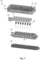
- Figure 7 is a partially exploded view of components of a connector assembly 790 that includes a feedthrough interface 786, a lower contact housing 770, contacts 769, spacers 771, a retention block 792, an upper contact housing 772, and an optional connector housing 791 disposed over the remainder of the connector assembly.
- the upper and lower contact housing 772, 770, contacts 769, and spacers 771 define one or more connectors lumens 767 that receive the proximal end of a lead or lead extension.
- the feedthrough interface 786 includes a ferrule 787 and a ceramic feedthrough 788.
- Figure 8A is a top view of the feedthrough interface 786 and illustrates other components such as contact receptacles 763 and contacts 769 disposed on the feedthrough interface.
- Figures 8B is a bottom view of a portion of the feedthrough interface 786 with additional components attached such as the contact receptacles 763 and wires 768.
- the wires 768 extend from the contacts 769 through the ceramic feedthrough 788 and, during assembly, can be attached to contacts or wires of, or from, the electronic subassembly 558 ( Figure 5 ) in the sealed housing 554 ( Figure 5 ).
- the ferrule 787 is made of metal and, at least in some embodiments, is welded to the sealed housing 554 ( Figure 5 ) during assembly of the device.
- the ferrule 787 can be made of any suitable metal including, but not limited to, titanium, titanium alloy, or the like.
- the ferrule 787 forms a perimeter around the ceramic feedthrough 788.
- the ferrule 787 may include at least one cross-bar 787a that separates at least a portion of the ceramic feedthrough 788 into two or more regions, as illustrated in Figure 8B .
- the ceramic feedthrough 788 electrically isolates the wires 768 from each other and is preferably brazed or otherwise attached to the ferrule 787. Any suitable braze can be used and may depend upon the materials of the ferrule 787 and the ceramic feedthrough 788. As an example, example, a gold braze may be used for a titanium ferrule and an aluminum oxide ceramic feedthrough. In at least some embodiments, the wires 768 are also brazed to the ceramic feedthrough 788. In at least some embodiments, the welding of the ferrule to the sealed housing 554 ( Figure 5 ) and the brazing of the ceramic feedthrough 788 and wires 768 to the ferrule result in a hermetic seal between the feedthrough interface 786 and the sealed housing 554.
- Any suitable ceramic can be used for the ceramic feedthrough 788 including, but not limited to, aluminum oxide or the like. Any suitable method can be used for forming the ceramic feedthrough 788 including, but not limited to, molding, such as injection molding, or the like.
- Figure 8A illustrates one embodiment of a lower contact housing 770 which includes multiple receptacles 763.
- Figures 9A to 9C illustrate another embodiment of a lower contact housing 770'.
- Figure 9A is a top view and
- Figure 9B is a bottom view of a portion of the combined ceramic feedthrough 788 and lower contact housing 770'.
- Figure 9C is a top view of the combined ceramic feedthrough 788 and lower contact housing 770' disposed on the ferrule 787.
- the lower contact housing 770 may be made of ceramic and can be made of the same ceramic or a different ceramic used in forming the ceramic feedthrough 788.
- the ceramic feedthrough 788 and lower contact housing 770 are formed together using, for example, molding, such as injection molding.
- the lower contact housing 770, 770' includes an optional base 774 (which may be part of the ceramic feedthrough 788) and multiple contact receptacles 763 arranged in one or more rows.
- the lower contact housing 770' of Figures 9A to 9C differs from lower contact housing 770 of Figure 8A , at least in part, in that the base 774 includes extensions 778 to one or both sides of the rows of contact receptacles 763 and includes outer connections 751 (better viewed in Figure 7 ) between the contact receptacles.
- the extensions 778 may define, in part, one or both of an insertion opening for inserting a lead at one end of each row of contact receptacles 763, a position for a retention block 792 ( Figure 7 ), or a lead stop at another end of each row of contact receptacles.
- the contact receptacles 763 are arranged in two rows for receiving two proximal lead (or lead extension) ends. In other embodiments, there may be one, three, four, or more rows. In the illustrated embodiments, there are eight contact receptacles in each row for a total of 16 contact receptacles. In other embodiments, there may be any number of contact receptacles per row including, for example, 2, 4, 6, 8, 10, 12, 16 or more contact receptacles in each row.
- the wire 768 is at least partially inserted into the wire hole 775 and then attached (for example, by welding) to the contact 769. As described above, once seated, the wire 768 can be brazed to the ceramic feedthrough (and, optionally, to the contact receptacle 771.) In at least some embodiments, this arrangement of contact 769, wire 768, and wire hole 775 can be easier to manufacture and assemble than corresponding arrangements in conventional connector assemblies.
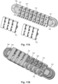
- Figures 10A to 10C illustrate different embodiments of suitable contacts 769 with attached wire 768. It will be understood, however, that other contacts can be used.
- Figure 10A illustrates one embodiment of a coiled or doughnut-shaped contact 769, such as a canted coil available from Bal Seal Engineering (Foothills Collins, CA).
- Figure 10B illustrates one embodiment of a contact 769 that includes bent fingers that receive and contact terminals on a lead or lead extension. Examples of this type of contact and other, similar, suitable contacts can be found in, for example, U.S. Patents Nos. 9,604,068 and 9,770,598 .
- Figure 10C illustrates a shaped wire contact 769 with multiple inward protrusions 1010 for contacting terminals of a lead or lead extension and multiple outward protrusions 1012 for seating within the upper and lower contact housing 772, 770 with overlapping ends 1014, 1106 of wire (for example, platinum/iridium wire). Examples of this type of contact can be found in U.S. Patent No. 7,803,021 .
- the ends 1014, 1016 or other parts of the contact 769 can be brazed in place in the upper or lower contact housing 772, 770.
- Other examples of suitable contacts can be found in, for example, U.S.
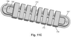
- FIG 11A the upper contact housing 772 is illustrated prior to attachment to the lower contact housing 770.
- Figure 11B illustrates a portion of the upper contact housing 772 attached to the lower contact housing 770 with spacers 771 inserted between the receptacles 763.
- Figure 11 C illustrates another view of the upper contact housing 772 attached to the lower contact housing 770 with some of the spacers 771 inserted.
- the lower contact housing 770 can be made of any suitable non-conductive material including, but not limited to, plastic or ceramic materials.
- the upper contact housing 772 may have receptacles similar to the receptacles 763 in the lower contact housing 770 with a similar contact receiving groove into which the contact 769 fits.
- the upper and lower contact housings 772, 770 hold the contacts 769 in place within the connector assembly 790.
- the upper and lower contact housing 772, 770 provide a housing for multiple contacts 769 in contrast the separate contact housings in many conventional connector assemblies.
- an adhesive such as silicone adhesive or epoxy
- a syringe may be used to inject the adhesive into the channel 777.
- the spacers 771 are made of any suitable non-conductive material including, but not limited to, flexible or resilient plastics, such as silicone, polyurethane, or the like. In at least some embodiments, spacers 771 form a seal between the receptacles in the upper and lower contact housings 772, 770 and may impede or prevent flow of fluid out of the lumen 767 in the connector assembly 790.
- an optional retention block 792 ( Figure 7 ) is attached at the entrance of the connector lumen 767.
- the retention block 792 may receive a fastener 594 ( Figure 5 ), such as a screw, pin, or other component, that can interact with the lead or lead extension to hold the lead or lead extension within the connector assembly 790.
- a fastener 594 such as a screw, pin, or other component
- Examples of retention blocks 792 and fasteners can be found at U.S. Patent No. 8,548,582 ; U.S. Patent Application Publication No. 2018/0008832 ; and U.S. Patent Applications Serial Nos. 15/878,085 and 15/905,499 .
- a connector housing 791 ( Figure 7 ) can be formed over the remainder of the connector assembly 790.
- the connector housing 791 can be made of any suitable material including, but not limited to, plastics, such as silicone, polyurethane, epoxy, or the like.
- the connector housing 791 may be formed by molding, casting, or any other suitable method.
- the connector housing 791 can be molded over the other components of the connector assembly 790.
- the connector housing 791 may be attached over the other components of the connector assembly 790 using an adhesive or mechanical fasteners, such as snaps, screws, bolts, or the like.
- Figure 12 is a schematic overview of one embodiment of components of an electrical stimulation system 1200 including an electronic subassembly 1258 disposed within a control module.
- the electronic subassembly 1258 may include one or more components of the IPG. It will be understood that the electrical stimulation system can include more, fewer, or different components and can have a variety of different configurations including those configurations disclosed in the stimulator references cited herein.
- a power source 1212 for example, a power source 1212, an antenna 1218, a receiver 1202, and a processor 1204
- the electrical stimulation system can be positioned on one or more circuit boards or similar carriers within a sealed housing of an implantable pulse generator (see e.g., 14 in Figure 1 ), if desired.
- Any power source 1212 can be used including, for example, a battery such as a primary battery or a rechargeable battery.
- Examples of other power sources include super capacitors, nuclear or atomic batteries, mechanical resonators, infrared collectors, thermally-powered energy sources, flexural powered energy sources, bioenergy power sources, fuel cells, bioelectric cells, osmotic pressure pumps, and the like including the power sources described in U.S. Patent No. 7,437,193 .
- power can be supplied by an external power source through inductive coupling via the optional antenna 1218 or a secondary antenna.
- the antenna 1218 (or the secondary antenna) is implemented using the auxiliary electrically-conductive conductor.
- the external power source can be in a device that is mounted on the skin of the user or in a unit that is provided near the user on a permanent or periodic basis.
- the battery may be recharged using the optional antenna 1218, if desired. Power can be provided to the battery for recharging by inductively coupling the battery through the antenna to a recharging unit 1216 external to the user. Examples of such arrangements can be found in the references identified above.
- the electronic subassembly 1258 and, optionally, the power source 1212 can be disposed within a control module (e.g., the IPG 14 or the ETS 20 of Figure 1 ).
- electrical stimulation signals are emitted by the electrodes (e.g., 26 in Figure 1 ) to stimulate nerve fibers, muscle fibers, or other body tissues near the electrical stimulation system.
- the processor 1204 is generally included to control the timing and electrical characteristics of the electrical stimulation system. For example, the processor 1204 can, if desired, control one or more of the timing, frequency, strength, duration, and waveform of the pulses. In addition, the processor 1204 can select which electrodes can be used to provide stimulation, if desired. In some embodiments, the processor 1204 selects which electrode(s) are cathodes and which electrode(s) are anodes. In some embodiments, the processor 1204 is used to identify which electrodes provide the most useful stimulation of the desired tissue.
- Any processor can be used and can be as simple as an electronic device that, for example, produces pulses at a regular interval or the processor can be capable of receiving and interpreting instructions from an external programming unit 1208 that, for example, allows modification of pulse characteristics.
- the processor 1204 is coupled to a receiver 1202 which, in turn, is coupled to the optional antenna 1218. This allows the processor 1204 to receive instructions from an external source to, for example, direct the pulse characteristics and the selection of electrodes, if desired.
- the antenna 1218 is capable of receiving signals (e.g., RF signals) from an external telemetry unit 1206 which is programmed by the programming unit 1208.
- the programming unit 1208 can be external to, or part of, the telemetry unit 1206.
- the telemetry unit 1206 can be a device that is worn on the skin of the user or can be carried by the user and can have a form similar to a pager, cellular phone, or remote control, if desired.
- the telemetry unit 1206 may not be worn or carried by the user but may only be available at a home station or at a clinician's office.
- the programming unit 1208 can be any unit that can provide information to the telemetry unit 1206 for transmission to the electrical stimulation system 1200.
- the programming unit 1208 can be part of the telemetry unit 1206 or can provide signals or information to the telemetry unit 1206 via a wireless or wired connection.
- One example of a suitable programming unit is a computer operated by the user or clinician to send signals to the telemetry unit 1206.
- the signals sent to the processor 1204 via the antenna 1218 and the receiver 1302 can be used to modify or otherwise direct the operation of the electrical stimulation system.
- the signals may be used to modify the pulses of the electrical stimulation system such as modifying one or more of pulse duration, pulse frequency, pulse waveform, and pulse strength.
- the signals may also direct the electrical stimulation system 1200 to cease operation, to start operation, to start charging the battery, or to stop charging the battery.
- the stimulation system does not include the antenna 1218 or receiver 1202 and the processor 1204 operates as programmed.
- the electrical stimulation system 1200 may include a transmitter (not shown) coupled to the processor 1204 and the antenna 1218 for transmitting signals back to the telemetry unit 1206 or another unit capable of receiving the signals.
- the electrical stimulation system 1200 may transmit signals indicating whether the electrical stimulation system 1200 is operating properly or not or indicating when the battery needs to be charged or the level of charge remaining in the battery.
- the processor 1204 may also be capable of transmitting information about the pulse characteristics so that a user or clinician can determine or verify the characteristics.
Claims (15)
- Verbinderanordnung (590; 790) für eine implantierbare Vorrichtung, wobei die Verbinderanordnung aufweist:eine Durchführungsschnittstelle (586; 786), die eine keramische Durchführung (788) und eine Hülse (787) aufweist, die an der keramischen Durchführung (788) befestigt ist und einen Umfang um diese herum bildet;ein unteres Kontaktgehäuse (770), das mit der Durchführungsschnittstelle (586; 786) gekoppelt ist, wobei das untere Kontaktgehäuse (770) und die Keramikdurchführung (788) mehrere Drahtlöcher definieren, die sich durch sie hindurch erstrecken;ein oberes Kontaktgehäuse (772), das am unteren Kontaktgehäuse (770) befestigt ist, wobei das obere und das untere Kontaktgehäuse gemeinsam mehrere Kontaktaufnahmen (763) definieren und mindestens ein Leitungsaufnahmelumen definieren, das sich durch mehrere der Kontaktaufnahmen (763) erstreckt und konfiguriert ist, einen Abschnitt einer Leitung oder Leitungsverlängerung aufzunehmen, der in das jeweilige Leitungsaufnahmelumen eingeführt wird, wobei jede der Kontaktaufnahmen (763) eine Öffnung für mindestens eines der Drahtlöcher definiert;mehrere Verbinderkontakte (769), wobei jeder Verbinderkontakt in einer der Kontaktaufnahmen (763) angeordnet ist und eine Leitungsaufnahmeöffnung definiert, die mit einem des mindestens einen Leitungsaufnahmelumens ausgerichtet ist; undmehrere Drähte (768), wobei jeder der Drähte mit einem der Verbinderkontakte (769) gekoppelt ist und sich durch eines der Drahtlöcher erstreckt, so dass der jeweilige Draht (768) aus der Keramikdurchführung (788) herausragt.
- Verbinderanordnung nach Anspruch 1, wobei das untere Kontaktgehäuse aus Keramik besteht.
- Verbinderanordnung nach Anspruch 2, wobei das untere Kontaktgehäuse und die Keramikdurchführung aus einem einzigen gegossenen Keramikstück bestehen.
- Verbinderanordnung nach einem der Ansprüche 2 oder 3, wobei die Drähte an die Keramikdurchführung und wahlweise an das untere Kontaktgehäuse hartgelötet sind.
- Verbinderanordnung nach einem der Ansprüche 1 bis 4, wobei die Hülse durch Hartlöten an der Keramikdurchführung befestigt ist.
- Verbinderanordnung nach einem der Ansprüche 1 bis 5, wobei das obere Kontaktgehäuse ein Polymer- oder Keramikmaterial aufweist.
- Verbinderanordnung nach einem der Ansprüche 1 bis 6, die ferner ein nichtleitendes Verbindergehäuse aufweist, das über dem oberen und unteren Kontaktgehäuse angeordnet ist.
- Verbinderanordnung nach einem der Ansprüche 1 bis 7, wobei jeder der Drähte direkt an einem der Verbinderkontakte befestigt ist.
- Verbinderanordnung nach einem der Ansprüche 1 bis 8, die ferner mehrere Abstandshalter aufweist, wobei jeder Abstandshalter zwischen einem Paar von Kontaktaufnahmen angeordnet ist.
- Verbinderanordnung nach einem der Ansprüche 1 bis 9, die ferner eine Klebekopplung des oberen Kontaktgehäuses mit dem unteren Kontaktgehäuse aufweist.
- Implantierbares Steuermodul für ein elektrisches Stimulationssystem, wobei das Steuermodul aufweist:die Verbinderanordnung nach einem der Ansprüche 1 bis 10;ein Gehäuse, das an der Durchführungsschnittstelle der Verbinderanordnung befestigt ist; undeine elektronische Unteranordnung, die im Gehäuse angeordnet und elektrisch mit den Drähten gekoppelt ist, die sich durch die Keramikdurchführung erstrecken.
- Implantierbares Steuermodul nach Anspruch 11, wobei die Hülse der Verbinderanordnung mit dem Gehäuse verschweißt ist.
- Implantierbares Steuermodul nach Anspruch 12, wobei das Gehäuse und die Durchführungsschnittstelle einen hermetisch abgedichteten Hohlraum bilden, in dem die elektronische Unteranordnung angeordnet ist.
- Elektrisches Stimulationssystem, das aufweist:das implantierbare Steuermodul nach einem der Ansprüche 11 bis 13; undeine elektrische Stimulationsleitung, die einen proximalen Abschnitt, einen distalen Abschnitt, mehrere Anschlüsse, die entlang des proximalen Abschnitts angeordnet sind, mehrere Elektroden, die entlang des distalen Abschnitts angeordnet sind, und mehrere Leiter aufweist, die die Anschlüsse mit den Elektroden elektrisch koppeln, wobei der proximale Abschnitt der elektrischen Stimulationsleitung zum Einführen in die Verbinderanordnung des implantierbaren Steuermoduls konfiguriert ist.
- Elektrisches Stimulationssystem nach Anspruch 14, das ferner eine Leitungsverlängerung aufweist, die einen proximalen Abschnitt, einen distalen Abschnitt, mehrere Anschlüsse, die entlang des proximalen Abschnitts angeordnet sind, einen Verbinder, der entlang des distalen Abschnitts angeordnet ist, mehrere Verbinderkontakte, die innerhalb des Verbinders angeordnet sind, und mehrere Leiter aufweist, die die Anschlüsse mit den Verbinderkontakten elektrisch koppeln, wobei der proximale Abschnitt der elektrischen Stimulationsleitung zum Einführen in den Verbinder der Leitungsverlängerung konfiguriert ist und der proximale Abschnitt der Stimulationsleitungsverlängerung zum Einführen in die Verbinderanordnung des implantierbaren Steuermoduls konfiguriert ist.
Applications Claiming Priority (2)
| Application Number | Priority Date | Filing Date | Title |
|---|---|---|---|
| US201862670412P | 2018-05-11 | 2018-05-11 | |
| PCT/US2019/031108 WO2019217415A1 (en) | 2018-05-11 | 2019-05-07 | Connector assembly for an electrical stimulation system |
Publications (2)
| Publication Number | Publication Date |
|---|---|
| EP3790623A1 EP3790623A1 (de) | 2021-03-17 |
| EP3790623B1 true EP3790623B1 (de) | 2023-07-05 |
Family
ID=66625328
Family Applications (1)
| Application Number | Title | Priority Date | Filing Date |
|---|---|---|---|
| EP19725520.1A Active EP3790623B1 (de) | 2018-05-11 | 2019-05-07 | Verbinderanordnung für ein system zur elektrischen stimulation |
Country Status (3)
| Country | Link |
|---|---|
| US (1) | US11052259B2 (de) |
| EP (1) | EP3790623B1 (de) |
| WO (1) | WO2019217415A1 (de) |
Families Citing this family (1)
| Publication number | Priority date | Publication date | Assignee | Title |
|---|---|---|---|---|
| CN117881455A (zh) * | 2021-06-07 | 2024-04-12 | 贝克顿·迪金森公司 | 连接器组件 |
Family Cites Families (415)
| Publication number | Priority date | Publication date | Assignee | Title |
|---|---|---|---|---|
| US3222471A (en) | 1963-06-10 | 1965-12-07 | Ripley Company Inc | Multiple electrical connector with longitudinal spaced contacts carried by insulating key |
| US3601747A (en) | 1969-09-18 | 1971-08-24 | Singer General Precision | Brush block retractor and alignment device |
| US3771106A (en) | 1971-04-14 | 1973-11-06 | New Nippon Electric Co | Socket suited for revolving the lamp attached thereto |
| US3718142A (en) | 1971-04-23 | 1973-02-27 | Medtronic Inc | Electrically shielded, gas-permeable implantable electro-medical apparatus |
| US3757789A (en) | 1971-10-26 | 1973-09-11 | I Shanker | Electromedical stimulator lead connector |
| US3908668A (en) | 1974-04-26 | 1975-09-30 | Medtronic Inc | Tissue stimulator with sealed lead connector |
| US3951154A (en) | 1974-04-30 | 1976-04-20 | Medtronic, Inc. | Lead connector for electro-medical device |
| US4003616A (en) | 1975-12-03 | 1977-01-18 | Clairol Incorporated | Swivelling electrical connector |
| US3990727A (en) | 1976-01-26 | 1976-11-09 | Stephen Franics Gallagher | Quick detachable coupler |
| US4112953A (en) | 1977-03-11 | 1978-09-12 | Medcor, Inc. | Pacer stimulator with improved lead connector |
| US4180078A (en) | 1978-04-07 | 1979-12-25 | Medtronic, Inc. | Lead connector for a body implantable stimulator |
| US4142532A (en) | 1978-04-07 | 1979-03-06 | Medtronic, Inc. | Body implantable stimulator with novel connector and method |
| USRE31990E (en) | 1978-11-22 | 1985-09-24 | Intermedics, Inc. | Multiple function lead assembly and method for inserting assembly into an implantable tissue stimulator |
| US4245642A (en) | 1979-06-28 | 1981-01-20 | Medtronic, Inc. | Lead connector |
| US4259962A (en) | 1979-08-24 | 1981-04-07 | Cordis Corporation | Sealing system for cardiac pacer lead connector |
| US4310001A (en) | 1980-04-21 | 1982-01-12 | Medtronic, Inc. | Connector assembly for body implantable medical systems |
| US4364625A (en) | 1980-06-12 | 1982-12-21 | Bell Telephone Laboratories, Incorporated | Electrical jack assembly |
| US4367907A (en) | 1980-08-04 | 1983-01-11 | Magnetic Controls Company | Circuit monitoring jack |
| US4630611A (en) | 1981-02-02 | 1986-12-23 | Medtronic, Inc. | Orthogonally-sensing lead |
| US4411276A (en) | 1981-04-28 | 1983-10-25 | Medtronic, Inc. | Implantable multiple connector |
| US4411277A (en) | 1981-04-28 | 1983-10-25 | Medtronic, Inc. | Implantable connector |
| US4461194A (en) | 1982-04-28 | 1984-07-24 | Cardio-Pace Medical, Inc. | Tool for sealing and attaching a lead to a body implantable device |
| US4466441A (en) | 1982-08-02 | 1984-08-21 | Medtronic, Inc. | In-line and bifurcated cardiac pacing lead connector |
| US4516820A (en) | 1983-01-27 | 1985-05-14 | The Commonwealth Of Australia | Cochlear prosthesis package connector |
| US4540236A (en) | 1983-07-18 | 1985-09-10 | Cordis Corporation | Quick lock/quick release connector |
| US4695116A (en) | 1984-02-27 | 1987-09-22 | Switchcraft, Inc. | Stacked electrical jacks |
| US4602624A (en) | 1984-10-11 | 1986-07-29 | Case Western Reserve University | Implantable cuff, method of manufacture, and method of installation |
| US4603696A (en) | 1985-02-14 | 1986-08-05 | Medtronic, Inc. | Lead connector |
| US4614395A (en) | 1985-04-04 | 1986-09-30 | Cordis Corporation | Quick connector to medical electrical lead |
| US4695117A (en) | 1985-06-03 | 1987-09-22 | Switchcraft, Inc. | Jack module and jackfield |
| US4832032A (en) | 1985-08-16 | 1989-05-23 | La Jolla Technology, Inc. | Electrical apparatus protective interconnect |
| JPH0232241Y2 (de) | 1985-10-02 | 1990-09-03 | ||
| US4995389A (en) | 1985-12-16 | 1991-02-26 | Telectronics Pacing Systems, Inc. | Multielectrode quick connect cardiac pacing lead connector assembly |
| US4715380A (en) | 1986-04-03 | 1987-12-29 | Telectronics N.V. | Capped pacer neck containing a connector assembly |
| US4860750A (en) | 1986-04-17 | 1989-08-29 | Intermedics Inc. | Sidelock pacer lead connector |
| US4712557A (en) | 1986-04-28 | 1987-12-15 | Cordis Leads, Inc. | A pacer including a multiple connector assembly with removable wedge and method of use |
| GB2199452B (en) | 1986-12-27 | 1991-09-18 | Iizuka Electric Ind Co Ltd | Electric jack |
| US4744370A (en) | 1987-04-27 | 1988-05-17 | Cordis Leads, Inc. | Lead assembly with selectable electrode connection |
| DE3718913A1 (de) | 1987-06-05 | 1988-12-22 | Siemens Ag | Verbindungsanordnung |
| US4784141A (en) | 1987-08-04 | 1988-11-15 | Cordis Leads, Inc. | Lead locking mechanism for cardiac pacers |
| US4850359A (en) | 1987-10-16 | 1989-07-25 | Ad-Tech Medical Instrument Corporation | Electrical brain-contact devices |
| US4869255A (en) | 1987-12-04 | 1989-09-26 | Ad-Tech Medical Instrument Corp. | Electrical connection device |
| US4898173A (en) | 1988-04-22 | 1990-02-06 | Medtronic, Inc. | In-line pacemaker connector system |
| US5070605A (en) | 1988-04-22 | 1991-12-10 | Medtronic, Inc. | Method for making an in-line pacemaker connector system |
| US5007435A (en) | 1988-05-25 | 1991-04-16 | Medtronic, Inc. | Connector for multiconductor pacing leads |
| US5000194A (en) | 1988-08-25 | 1991-03-19 | Cochlear Corporation | Array of bipolar electrodes |
| US4951687A (en) | 1989-01-31 | 1990-08-28 | Medtronic, Inc. | Medical electrical lead connector |
| US5007864A (en) | 1989-11-27 | 1991-04-16 | Siemens-Pacesetter, Inc. | Device for adapting a pacemaker lead to a pacemaker |
| US5000177A (en) | 1990-01-29 | 1991-03-19 | Cardiac Pacemakers, Inc. | Bipolar lead adapter with resilient housing and rigid retainers for plug seals |
| US5086773A (en) | 1990-09-10 | 1992-02-11 | Cardiac Pacemakers, Inc. | Tool-less pacemaker lead assembly |
| US5135001A (en) | 1990-12-05 | 1992-08-04 | C. R. Bard, Inc. | Ultrasound sheath for medical diagnostic instruments |
| US5082453A (en) | 1991-05-16 | 1992-01-21 | Siemens-Pacesetter, Inc. | Multi-contact connector system for an implantable medical device |
| JPH0511600A (ja) | 1991-07-06 | 1993-01-22 | Fujitsu Ltd | 一成分現像剤を使用する静電記録装置 |
| US5201865A (en) | 1991-10-28 | 1993-04-13 | Medtronic, Inc. | Medical lead impedance measurement system |
| US5241957A (en) | 1991-11-18 | 1993-09-07 | Medtronic, Inc. | Bipolar temporary pacing lead and connector and permanent bipolar nerve wire |
| US5312439A (en) | 1991-12-12 | 1994-05-17 | Loeb Gerald E | Implantable device having an electrolytic storage electrode |
| US5193539A (en) | 1991-12-18 | 1993-03-16 | Alfred E. Mann Foundation For Scientific Research | Implantable microstimulator |
| US5358514A (en) | 1991-12-18 | 1994-10-25 | Alfred E. Mann Foundation For Scientific Research | Implantable microdevice with self-attaching electrodes |
| US5193540A (en) | 1991-12-18 | 1993-03-16 | Alfred E. Mann Foundation For Scientific Research | Structure and method of manufacture of an implantable microstimulator |
| US5261395A (en) | 1992-03-02 | 1993-11-16 | Cardiac Pacemaker, Inc. | Tooless pulse generator to lead connection |
| US5324312A (en) | 1992-05-06 | 1994-06-28 | Medtronic, Inc. | Tool-less threaded connector assembly |
| US5330521A (en) | 1992-06-29 | 1994-07-19 | Cohen Donald M | Low resistance implantable electrical leads |
| EP0580928A1 (de) | 1992-07-31 | 1994-02-02 | ARIES S.r.l. | Katheter für eine Wirbelsäulenelektrode |
| US5252090A (en) | 1992-09-30 | 1993-10-12 | Telectronics Pacing Systems, Inc. | Self-locking implantable stimulating lead connector |
| US5374279A (en) | 1992-10-30 | 1994-12-20 | Medtronic, Inc. | Switchable connector block for implantable defibrillator |
| US5354326A (en) | 1993-01-27 | 1994-10-11 | Medtronic, Inc. | Screening cable connector for interface to implanted lead |
| US5383913A (en) | 1993-04-21 | 1995-01-24 | Schiff; Steven M. | Bidirectional lead connector for left or right sided implantation of pacemakers and/or other implantable electrophysiologic devices and a method for using the same |
| US5336246A (en) | 1993-06-23 | 1994-08-09 | Telectronics Pacing Systems, Inc. | Lead connector assembly for medical device and method of assembly |
| US5348481A (en) | 1993-09-29 | 1994-09-20 | Cardiometrics, Inc. | Rotary connector for use with small diameter flexible elongate member having electrical capabilities |
| US5413595A (en) | 1993-10-15 | 1995-05-09 | Pacesetter, Inc. | Lead retention and seal for implantable medical device |
| ZA948393B (en) | 1993-11-01 | 1995-06-26 | Polartechnics Ltd | Method and apparatus for tissue type recognition |
| US5368496A (en) | 1993-12-10 | 1994-11-29 | Tetrad Corporation | Connector assembly having control lever actuation |
| US5489225A (en) | 1993-12-16 | 1996-02-06 | Ventritex, Inc. | Electrical terminal with a collet grip for a defibrillator |
| US5486202A (en) | 1993-12-17 | 1996-01-23 | Intermedics, Inc. | Cardiac stimulator lead connector |
| US5458629A (en) | 1994-02-18 | 1995-10-17 | Medtronic, Inc. | Implantable lead ring electrode and method of making |
| US5435731A (en) | 1994-05-12 | 1995-07-25 | Kang; Steve | Rotatable hidden connector for telephone transmitter |
| US5522874A (en) | 1994-07-28 | 1996-06-04 | Gates; James T. | Medical lead having segmented electrode |
| US5560358A (en) | 1994-09-08 | 1996-10-01 | Radionics, Inc. | Connector design for multi-contact medical electrode |
| US5582180A (en) | 1994-11-04 | 1996-12-10 | Physio-Control Corporation | Combination three-twelve lead electrocardiogram cable |
| US5534019A (en) | 1994-12-09 | 1996-07-09 | Ventritex, Inc. | Cardiac defibrillator with case that can be electrically active or inactive |
| US5509928A (en) | 1995-03-02 | 1996-04-23 | Pacesetter, Inc. | Internally supported self-sealing septum |
| US5626626A (en) | 1995-05-17 | 1997-05-06 | Ventritex, Inc. | Implantable medical apparatus with magnifying header |
| US5545188A (en) | 1995-06-05 | 1996-08-13 | Intermedics, Inc. | Cardiac pacemaker with collet-type lead connector |
| US5545189A (en) | 1995-11-02 | 1996-08-13 | Ventritex, Inc. | Case-activating switch assembly for an implantable cardiac stimulation device |
| US5669790A (en) | 1995-12-07 | 1997-09-23 | Ventritex, Inc. | Lead lumen sealing device |
| US5679026A (en) | 1995-12-21 | 1997-10-21 | Ventritex, Inc. | Header adapter for an implantable cardiac stimulation device |
| US5766042A (en) | 1995-12-28 | 1998-06-16 | Medtronic, Inc. | Tool-less locking and sealing assembly for implantable medical device |
| SE9600311D0 (sv) | 1996-01-29 | 1996-01-29 | Pacesetter Ab | Fixeringsanordning |
| US6051017A (en) | 1996-02-20 | 2000-04-18 | Advanced Bionics Corporation | Implantable microstimulator and systems employing the same |
| DE19609367A1 (de) | 1996-03-04 | 1997-09-11 | Biotronik Mess & Therapieg | Herzschrittmacher |
| ATE302633T1 (de) | 1996-03-07 | 2005-09-15 | Axon Engineering Inc | Polymer-metall folienstruktur für neuronale stimulationselektroden |
| US5713922A (en) | 1996-04-25 | 1998-02-03 | Medtronic, Inc. | Techniques for adjusting the locus of excitation of neural tissue in the spinal cord or brain |
| US5711316A (en) | 1996-04-30 | 1998-01-27 | Medtronic, Inc. | Method of treating movement disorders by brain infusion |
| US5951595A (en) | 1996-05-13 | 1999-09-14 | Pacesetteer, Inc. | Setscrewless connector assembly for implantable medical devices |
| DE19622669A1 (de) | 1996-06-05 | 1997-12-11 | Implex Gmbh | Implantierbare Einheit |
| US5837006A (en) | 1996-09-10 | 1998-11-17 | Medtronic, Inc. | Retraction stop for helical medical lead electrode |
| US5730628A (en) | 1996-09-25 | 1998-03-24 | Pacesetter, Inc. | Multi-contact connector for an implantable medical device |
| US5843148A (en) | 1996-09-27 | 1998-12-01 | Medtronic, Inc. | High resolution brain stimulation lead and method of use |
| US5796044A (en) | 1997-02-10 | 1998-08-18 | Medtronic, Inc. | Coiled wire conductor insulation for biomedical lead |
| US6208894B1 (en) | 1997-02-26 | 2001-03-27 | Alfred E. Mann Foundation For Scientific Research And Advanced Bionics | System of implantable devices for monitoring and/or affecting body parameters |
| AU6667698A (en) | 1997-02-26 | 1998-09-18 | Alfred E. Mann Foundation For Scientific Research | Battery-powered patient implantable device |
| US6164284A (en) | 1997-02-26 | 2000-12-26 | Schulman; Joseph H. | System of implantable devices for monitoring and/or affecting body parameters |
| JP3774237B2 (ja) | 1997-03-25 | 2006-05-10 | ラディ・メディカル・システムズ・アクチェボラーグ | 雌型接続具 |
| US5800495A (en) | 1997-03-27 | 1998-09-01 | Sulzer Intermedics Inc. | Endocardial lead assembly |
| US5843141A (en) | 1997-04-25 | 1998-12-01 | Medronic, Inc. | Medical lead connector system |
| US5782892A (en) | 1997-04-25 | 1998-07-21 | Medtronic, Inc. | Medical lead adaptor for external medical device |
| US5931861A (en) | 1997-04-25 | 1999-08-03 | Medtronic, Inc. | Medical lead adaptor having rotatable locking clip mechanism |
| US6080188A (en) | 1997-06-16 | 2000-06-27 | Medtronic, Inc. | Setscrew less lead connector system for medical devices |
| FR2765486B1 (fr) | 1997-07-03 | 1999-10-01 | Ela Medical Sa | Systeme d'immobilisation mecanique d'un connecteur de sonde dans un connecteur de generateur de dispositif medical implantable actif, notamment pour un stimulateur cardiaque, defibrillateur et/ou cardioverteur |
| US7231253B2 (en) | 1997-08-01 | 2007-06-12 | Medtronic, Inc. | IMD connector header with grommet retainer |
| US5906634A (en) | 1997-08-08 | 1999-05-25 | Cardiac Pacemakers, Inc. | Implantable device having a quick connect mechanism for leads |
| JPH1169782A (ja) | 1997-08-11 | 1999-03-09 | Seiko Epson Corp | 電源回路及び液晶表示装置及び電子機器 |
| US6125302A (en) | 1997-09-02 | 2000-09-26 | Advanced Bionics Corporation | Precurved modiolar-hugging cochlear electrode |
| US6006135A (en) | 1997-09-26 | 1999-12-21 | Medtronic, Inc. | Apparatus for interconnecting implantable electrical leads and medical device |
| US5938688A (en) | 1997-10-22 | 1999-08-17 | Cornell Research Foundation, Inc. | Deep brain stimulation method |
| US6198969B1 (en) | 1998-02-12 | 2001-03-06 | Advanced Bionics Corporation | Implantable connector for multi-output neurostimulators |
| US5989077A (en) | 1998-03-13 | 1999-11-23 | Intermedics Inc | Connector for implantable medical device |
| US6167314A (en) | 1998-04-14 | 2000-12-26 | Intermedics Inc. | Cardiac pacemaker lead with pacemaker connector |
| US6161047A (en) | 1998-04-30 | 2000-12-12 | Medtronic Inc. | Apparatus and method for expanding a stimulation lead body in situ |
| US6134478A (en) | 1998-06-05 | 2000-10-17 | Intermedics Inc. | Method for making cardiac leads with zone insulated electrodes |
| US6224450B1 (en) | 1998-08-28 | 2001-05-01 | Laurie J. Norton | Cycling activity belt |
| AU4959799A (en) | 1998-06-26 | 2000-01-17 | Advanced Bionics Corporation | Programmable current output stimulus stage for implantable device |
| US6322559B1 (en) | 1998-07-06 | 2001-11-27 | Vnus Medical Technologies, Inc. | Electrode catheter having coil structure |
| US6018684A (en) | 1998-07-30 | 2000-01-25 | Cardiac Pacemakers, Inc. | Slotted pacing/shocking electrode |
| US6162101A (en) | 1998-09-03 | 2000-12-19 | Pmt Corporation | Connector assembly for electrodes |
| US6112121A (en) | 1998-09-09 | 2000-08-29 | Intermedics Inc. | Implantable medical device with positive indication of lead connection and connector therefor |
| SE9803692D0 (sv) | 1998-10-27 | 1998-10-27 | Pacesetter Ab | A connector for a heart stimulator |
| US6321126B1 (en) | 1998-12-07 | 2001-11-20 | Advanced Bionics Corporation | Implantable connector |
| DE69927717T2 (de) | 1998-12-23 | 2006-07-20 | Nuvasive Inc., San Diego | Vorrichtungen zur kannulation und zur nervenüberwachung |
| US6564078B1 (en) | 1998-12-23 | 2003-05-13 | Nuvasive, Inc. | Nerve surveillance cannula systems |
| US6393325B1 (en) | 1999-01-07 | 2002-05-21 | Advanced Bionics Corporation | Directional programming for implantable electrode arrays |
| US6154678A (en) | 1999-03-19 | 2000-11-28 | Advanced Neuromodulation Systems, Inc. | Stimulation lead connector |
| US6216045B1 (en) | 1999-04-26 | 2001-04-10 | Advanced Neuromodulation Systems, Inc. | Implantable lead and method of manufacture |
| US6167311A (en) | 1999-06-14 | 2000-12-26 | Electro Core Techniques, Llc | Method of treating psychological disorders by brain stimulation within the thalamus |
| US6516227B1 (en) | 1999-07-27 | 2003-02-04 | Advanced Bionics Corporation | Rechargeable spinal cord stimulator system |
| US7949395B2 (en) | 1999-10-01 | 2011-05-24 | Boston Scientific Neuromodulation Corporation | Implantable microdevice with extended lead and remote electrode |
| US6391985B1 (en) | 1999-10-21 | 2002-05-21 | Union Carbide Chemicals & Plastics Technology Corporation | High condensing mode polyolefin production under turbulent conditions in a fluidized bed |
| TW468807U (en) | 1999-11-05 | 2001-12-11 | Hon Hai Prec Ind Co Ltd | Fixed stand for the computer host |
| US6605094B1 (en) | 1999-11-19 | 2003-08-12 | Advanced Bionics Corporation | Integrated subcutaneous tunneling and carrying tool |
| US6556873B1 (en) | 1999-11-29 | 2003-04-29 | Medtronic, Inc. | Medical electrical lead having variable bending stiffness |
| US6609029B1 (en) | 2000-02-04 | 2003-08-19 | Advanced Bionics Corporation | Clip lock mechanism for retaining lead |
| DE60131952T2 (de) | 2000-02-09 | 2008-12-18 | Medtronic Transneuronix, Inc. | Medizinische implantierbare vorrichtung zur elektrostimulation mit diskreten mikroelektroden |
| US6271094B1 (en) | 2000-02-14 | 2001-08-07 | International Business Machines Corporation | Method of making MOSFET with high dielectric constant gate insulator and minimum overlap capacitance |
| US6370434B1 (en) | 2000-02-28 | 2002-04-09 | Cardiac Pacemakers, Inc. | Cardiac lead and method for lead implantation |
| US6430442B1 (en) | 2000-02-29 | 2002-08-06 | Medtronic, Inc. | Split contact with super elastic retaining ring for implantable medical device |
| SE0000779D0 (sv) | 2000-03-08 | 2000-03-08 | Pacesetter Ab | Process in connection with pacers |
| US6473654B1 (en) | 2000-03-08 | 2002-10-29 | Advanced Bionics Corporation | Lead anchor |
| US6741892B1 (en) | 2000-03-10 | 2004-05-25 | Advanced Bionics Corporation | Movable contact locking mechanism for spinal cord stimulator lead connector |
| US6397108B1 (en) | 2000-04-03 | 2002-05-28 | Medtronic Inc. | Safety adaptor for temporary medical leads |
| US6671534B2 (en) | 2000-04-19 | 2003-12-30 | Ad-Tech Medical Instrument Corporation | Electrical connector for multi-contact medical electrodes |
| US6415168B1 (en) | 2000-04-19 | 2002-07-02 | Ad-Tech Medical Instrument Corporation | Electrical connector for multi-contact medical electrodes |
| US6725096B2 (en) | 2000-05-05 | 2004-04-20 | Advanced Bionics Corporation | Multiple in-line contact connector |
| US6295944B1 (en) | 2000-06-20 | 2001-10-02 | J Timothy Lovett | Automatic tethering system for a floating dock |
| US6510347B2 (en) | 2000-08-17 | 2003-01-21 | William N. Borkan | Spinal cord stimulation leads |
| US6805675B1 (en) | 2000-09-12 | 2004-10-19 | Medtronic, Inc. | Method and apparatus for deflecting a screw-in lead |
| US6757970B1 (en) | 2000-11-07 | 2004-07-06 | Advanced Bionics Corporation | Method of making multi-contact electrode array |
| WO2002045795A2 (en) | 2000-12-07 | 2002-06-13 | Medtronic, Inc. | Directional brain stimulation and recording leads |
| US6319021B1 (en) | 2000-12-19 | 2001-11-20 | Hon Hai Precision Ind. Co., Ltd. | Power connector providing improved performance |
| US7033326B1 (en) | 2000-12-29 | 2006-04-25 | Advanced Bionics Corporation | Systems and methods of implanting a lead for brain stimulation |
| US6975906B2 (en) | 2001-02-08 | 2005-12-13 | Wilson Greatbatch Ltd. | One piece header assembly over molded to an implantable medical device |
| US6854994B2 (en) | 2001-04-19 | 2005-02-15 | Medtronic, Inc. | Medical electrical lead connector arrangement including anti-rotation means |
| GB0104982D0 (en) | 2001-02-28 | 2001-04-18 | Gill Steven | Electrode |
| US6498952B2 (en) | 2001-03-08 | 2002-12-24 | Pacesetter, Inc. | Hermetically sealed feedthrough connector using shape memory alloy for implantable medical device |
| US6428368B1 (en) | 2001-03-26 | 2002-08-06 | Pacesetter, Inc. | Side actuated lead connector assembly for implantable tissue stimulation device |
| US6921295B2 (en) | 2001-04-19 | 2005-07-26 | Medtronic, Inc. | Medical lead extension and connection system |
| US6466824B1 (en) | 2001-04-23 | 2002-10-15 | Medtronic, Inc. | Bi-atrial and/or bi-ventricular patient safety cable and methods regarding same |
| US6671553B1 (en) | 2001-05-23 | 2003-12-30 | Pacesetter, Inc. | Implantable cardiac lead having terminating connector strain relief and method of manufacture |
| US6968235B2 (en) | 2001-07-17 | 2005-11-22 | Medtronic, Inc. | Enhanced method and apparatus to identify and connect a small diameter lead with a low profile lead connector |
| US6799991B2 (en) | 2001-09-05 | 2004-10-05 | Medtronic, Inc. | Medical lead connector |
| US6662035B2 (en) * | 2001-09-13 | 2003-12-09 | Neuropace, Inc. | Implantable lead connector assembly for implantable devices and methods of using it |
| US7904161B2 (en) | 2001-10-22 | 2011-03-08 | Oscor Inc. | Lead adaptor having low resistance conductors and/or encapsulated housing |
| US7270568B2 (en) | 2001-10-22 | 2007-09-18 | Oscor Inc. | Adapter for electrical stimulation leads |
| US7128600B2 (en) | 2001-10-22 | 2006-10-31 | Oscor Inc. | Adapter for electrical stimulation leads |
| US6678564B2 (en) | 2001-12-06 | 2004-01-13 | Advanced Cochlear Systems, Inc. | Bio-implant and method of making the same |
| WO2003063951A1 (en) | 2002-01-29 | 2003-08-07 | Advanced Bionics Corporation | Lead assembly for implantable microstimulator |
| US6663570B2 (en) | 2002-02-27 | 2003-12-16 | Volcano Therapeutics, Inc. | Connector for interfacing intravascular sensors to a physiology monitor |
| US6895276B2 (en) | 2002-02-28 | 2005-05-17 | Medtronic, Inc. | In-line lead header for an implantable medical device |
| US8000802B2 (en) | 2002-04-22 | 2011-08-16 | Medtronic, Inc. | Implantable lead with coplanar contact coupling |
| US7027852B2 (en) | 2002-05-21 | 2006-04-11 | Pacesetter, Inc. | Lead with distal tip surface electrodes connected in parallel |
| US6757039B2 (en) | 2002-06-17 | 2004-06-29 | Yao-Dong Ma | Paper white cholesteric displays employing reflective elliptical polarizer |
| US7203548B2 (en) | 2002-06-20 | 2007-04-10 | Advanced Bionics Corporation | Cavernous nerve stimulation via unidirectional propagation of action potentials |
| US7860570B2 (en) | 2002-06-20 | 2010-12-28 | Boston Scientific Neuromodulation Corporation | Implantable microstimulators and methods for unidirectional propagation of action potentials |
| US7292890B2 (en) | 2002-06-20 | 2007-11-06 | Advanced Bionics Corporation | Vagus nerve stimulation via unidirectional propagation of action potentials |
| US7437193B2 (en) | 2002-06-28 | 2008-10-14 | Boston Scientific Neuromodulation Corporation | Microstimulator employing improved recharging reporting and telemetry techniques |
| FR2841689B1 (fr) | 2002-07-01 | 2010-12-10 | Dixi Microtechniques | Connecteur a contacts multiples pour electrode par exemple a usage medical |
| US7554493B1 (en) | 2002-07-08 | 2009-06-30 | Boston Scientific Neuromodulation Corporation | Folded monopole antenna for implanted medical device |
| US20040064164A1 (en) | 2002-09-30 | 2004-04-01 | Ries Andrew J. | Connector module jumper for quadrapolar leads |
| US7047084B2 (en) | 2002-11-20 | 2006-05-16 | Advanced Neuromodulation Systems, Inc. | Apparatus for directionally stimulating nerve tissue |
| US7539542B1 (en) | 2003-01-09 | 2009-05-26 | Boston Scientific Neuromodulation Corporation | Lead connector, lead adapter, and lead insertion apparatus |
| US6980863B2 (en) | 2003-03-20 | 2005-12-27 | Medtronic, Inc. | Neurological stimulation lead extension |
| US7110827B2 (en) | 2003-04-25 | 2006-09-19 | Medtronic, Inc. | Electrical connectors for medical lead having weld-less wiring connection |
| US8078280B2 (en) | 2003-04-25 | 2011-12-13 | Medtronic, Inc. | Implantable biomedical electrical connectors having integral side and inner walls |
| US7130699B2 (en) | 2003-05-13 | 2006-10-31 | Medtronic, Inc. | Medical lead adaptor assembly |
| US7242987B2 (en) | 2003-06-19 | 2007-07-10 | Medtronic, Inc. | Medical lead adaptor |
| US7164951B2 (en) | 2003-07-31 | 2007-01-16 | Medtronic, Inc. | Electrical connector assembly having integrated conductive element and elastomeric seal for coupling medical leads to implantable medical devices |
| US7647111B2 (en) | 2003-07-31 | 2010-01-12 | Medtronic, Inc. | Connector assembly for connecting a lead and an implantable medical device |
| US7769458B2 (en) | 2003-07-31 | 2010-08-03 | Medtronic, Inc. | Small format connector clip of an implantable medical device |
| US20050038489A1 (en) | 2003-08-14 | 2005-02-17 | Grill Warren M. | Electrode array for use in medical stimulation and methods thereof |
| US8065008B2 (en) | 2003-08-21 | 2011-11-22 | Medtronic, Inc. | Multi-polar electrical medical lead connector system |
| US8019420B2 (en) | 2003-08-21 | 2011-09-13 | Medtronic, Inc. | Medical lead connector systems with adapters |
| US8147486B2 (en) | 2003-09-22 | 2012-04-03 | St. Jude Medical, Atrial Fibrillation Division, Inc. | Medical device with flexible printed circuit |
| US7286882B2 (en) | 2003-10-03 | 2007-10-23 | Medtronic, Inc. | Implantable electrical connector system |
| US7512446B2 (en) | 2003-10-24 | 2009-03-31 | Medtronic, Inc. | Lead fixation tool |
| US20050159799A1 (en) | 2003-11-25 | 2005-07-21 | Advanced Neuromodulation Systems, Inc. | Percutaneous-insertion needle and method of implanting a lead |
| US6878013B1 (en) | 2003-12-02 | 2005-04-12 | Edgar G. Behan | Connector apparatus for a medical device |
| US7155283B2 (en) | 2003-12-11 | 2006-12-26 | Medtronic, Inc. | Connector header grommet for an implantable medical device |
| US7070455B2 (en) | 2004-02-23 | 2006-07-04 | Bal Seal Engineering Co., Inc. | Stackable assembly for direct connection between a pulse generator and a human body |
| US7108549B2 (en) | 2004-03-30 | 2006-09-19 | Medtronic, Inc. | Medical electrical connector |
| US7489971B1 (en) | 2004-06-05 | 2009-02-10 | Advanced Neuromodulation Systems, Inc. | Notched electrode for electrostimulation lead |
| US20060015163A1 (en) | 2004-07-19 | 2006-01-19 | Team Brown Enterprises, Llc | Lead extender for implantable device |
| WO2006015087A2 (en) | 2004-07-27 | 2006-02-09 | The Cleveland Clinic Foundation | Thalamic stimulation device |
| US7548788B2 (en) | 2004-08-04 | 2009-06-16 | Boston Scientific Neuromodulation Corporation | Operating room lead connector |
| US20060030204A1 (en) | 2004-08-09 | 2006-02-09 | Advanced Neuromodulation Systems, Inc. | System and method for providing strain relief for medical device leads |
| US7191009B2 (en) | 2004-08-09 | 2007-03-13 | Medtronic, Inc. | Means for increasing implantable medical device electrode surface area |
| CN101018583A (zh) | 2004-08-26 | 2007-08-15 | 巴尔密封工程有限公司 | 用于医疗电子装置的导电路径 |
| CN2740095Y (zh) | 2004-09-30 | 2005-11-16 | 汪恩光 | 双刀蔬果削皮器 |
| US7283878B2 (en) | 2004-10-12 | 2007-10-16 | Medtronic, Inc. | Lead stabilizer and extension wire |
| US7083474B1 (en) | 2004-12-08 | 2006-08-01 | Pacesetter, Inc. | System for lead retention and sealing of an implantable medical device |
| US20080255647A1 (en) | 2004-12-22 | 2008-10-16 | Marc Jensen | Implantable Addressable Segmented Electrodes |
| US20080077186A1 (en) | 2006-04-18 | 2008-03-27 | Proteus Biomedical, Inc. | High phrenic, low capture threshold pacing devices and methods |
| US7783359B2 (en) | 2005-01-05 | 2010-08-24 | Boston Scientific Neuromodulation Corporation | Devices and methods using an implantable pulse generator for brain stimulation |
| US7809446B2 (en) | 2005-01-05 | 2010-10-05 | Boston Scientific Neuromodulation Corporation | Devices and methods for brain stimulation |
| US8019439B2 (en) | 2005-01-11 | 2011-09-13 | Boston Scientific Neuromodulation Corporation | Lead assembly and method of making same |
| US8066702B2 (en) | 2005-01-11 | 2011-11-29 | Rittman Iii William J | Combination electrical stimulating and infusion medical device and method |
| US20060167522A1 (en) | 2005-01-25 | 2006-07-27 | Malinowski Zdzislaw B | Connector for use in an implantable stimulator device |
| US7422487B2 (en) | 2005-01-27 | 2008-09-09 | Oscos Inc. | Electrical connector and devices using the same |
| WO2006083884A1 (en) | 2005-01-31 | 2006-08-10 | Medtronic, Inc. | A medical lead with segmented electrode |
| US7168165B2 (en) | 2005-03-07 | 2007-01-30 | Medtronic, Inc. | Fabrication of electrical medical leads employing multi-filar wire conductors |
| US20060224208A1 (en) | 2005-04-05 | 2006-10-05 | Bal Seal Engineering Co., Inc. | Medical electronics electrical implantable medical devices |
| US8565898B2 (en) | 2005-04-28 | 2013-10-22 | Medtronic, Inc. | Rate control during AF using cellular intervention to modulate AV node |
| US8594807B2 (en) | 2005-05-02 | 2013-11-26 | Boston Scientific Neuromodulation Corporation | Compliant stimulating electrodes and leads and methods of manufacture and use |
| US7962213B2 (en) | 2005-05-12 | 2011-06-14 | Cardiac Pacemakers, Inc. | Interconnected electrode assembly for a lead connector and method therefor |
| US7316593B2 (en) | 2005-05-19 | 2008-01-08 | Bal Seal Engineering Co., Inc. | Electrical connector with embedded canted coil spring |
| US7822482B2 (en) | 2005-07-29 | 2010-10-26 | Medtronic, Inc. | Electrical stimulation lead with rounded array of electrodes |
| US7761165B1 (en) | 2005-09-29 | 2010-07-20 | Boston Scientific Neuromodulation Corporation | Implantable stimulator with integrated plastic housing/metal contacts and manufacture and use |
| US8271094B1 (en) | 2005-09-30 | 2012-09-18 | Boston Scientific Neuromodulation Corporation | Devices with cannula and electrode lead for brain stimulation and methods of use and manufacture |
| US7590451B2 (en) | 2005-10-31 | 2009-09-15 | Medtronic, Inc. | Axial lead connector for implantable medical devices |
| US7650184B2 (en) | 2005-12-01 | 2010-01-19 | Boston Scientific Neuromodulation Corporation | Cylindrical multi-contact electrode lead for neural stimulation and method of making same |
| US7610103B2 (en) | 2005-12-19 | 2009-10-27 | Boston Scientific Neuromodulation Corporation | Electrode arrangement for nerve stimulation and methods of treating disorders |
| US7672734B2 (en) | 2005-12-27 | 2010-03-02 | Boston Scientific Neuromodulation Corporation | Non-linear electrode array |
| US8700178B2 (en) | 2005-12-27 | 2014-04-15 | Boston Scientific Neuromodulation Corporation | Stimulator leads and methods for lead fabrication |
| US7244150B1 (en) | 2006-01-09 | 2007-07-17 | Advanced Bionics Corporation | Connector and methods of fabrication |
| US7241180B1 (en) | 2006-01-31 | 2007-07-10 | Medtronic, Inc. | Medical electrical lead connector assembly |
| US8380321B2 (en) | 2006-02-24 | 2013-02-19 | Medtronic, Inc. | Programming interface with a cross-sectional view of a stimulation lead with complex electrode array geometry |
| US7848802B2 (en) | 2006-02-24 | 2010-12-07 | Medtronic, Inc. | Programming interface with a concentric axial view of a stimulation lead with complex electrode array geometry |
| US7822483B2 (en) | 2006-02-24 | 2010-10-26 | Medtronic, Inc. | Electrical and activation field models for configuring stimulation therapy |
| EP1993658B1 (de) | 2006-03-02 | 2009-10-07 | St Jude Medical AB | Medizinische implantierbare leitung und verfahren zu ihrer herstellung |
| US8175710B2 (en) | 2006-03-14 | 2012-05-08 | Boston Scientific Neuromodulation Corporation | Stimulator system with electrode array and the method of making the same |
| WO2007109762A1 (en) | 2006-03-23 | 2007-09-27 | Medtronic, Inc. | Medical electrical lead connection systems and methods |
| US7526339B2 (en) | 2006-03-27 | 2009-04-28 | Medtronic, Inc. | IPG connector headers for implantable medical devices |
| US7974706B2 (en) | 2006-03-30 | 2011-07-05 | Boston Scientific Neuromodulation Corporation | Electrode contact configurations for cuff leads |
| US8321025B2 (en) | 2006-07-31 | 2012-11-27 | Cranial Medical Systems, Inc. | Lead and methods for brain monitoring and modulation |
| US7583999B2 (en) | 2006-07-31 | 2009-09-01 | Cranial Medical Systems, Inc. | Multi-channel connector for brain stimulation system |
| WO2008018067A2 (en) | 2006-08-07 | 2008-02-14 | Alpha Omega Engineering Ltd. | Cerebral electrodes and methods of operating same |
| US8224450B2 (en) | 2006-09-18 | 2012-07-17 | Boston Scientific Neuromodulation Corporation | Feed through interconnect assembly for an implantable stimulation system and methods of making and using |
| EP2559454A1 (de) | 2006-09-26 | 2013-02-20 | Sapiens Steering Brain Stimulation B.V. | Vorrichtung zur Gewebestimulation |
| EP2078263B1 (de) | 2006-10-31 | 2019-06-12 | Semiconductor Energy Laboratory Co, Ltd. | Halbleiterbauelement |
| US20080103580A1 (en) | 2006-10-31 | 2008-05-01 | Medtronic, Inc. | Implantable medical elongated member with dual purpose conduit |
| US7684873B2 (en) | 2006-10-31 | 2010-03-23 | Medtronic, Inc. | Implantable medical lead including a directional electrode and fixation elements along an interior surface |
| US20080114230A1 (en) | 2006-11-14 | 2008-05-15 | Bruce Addis | Electrode support |
| US7717754B2 (en) | 2006-12-07 | 2010-05-18 | Medtronic, Inc. | Connector assembly with internal seals and manufacturing method |
| US7979140B2 (en) | 2006-12-12 | 2011-07-12 | Alfred E. Mann Foundation For Scientific Research | Segmented electrode |
| WO2008072125A1 (en) | 2006-12-13 | 2008-06-19 | Koninklijke Philips Electronics, N.V. | First time right placement of a dbs lead |
| US7711428B2 (en) | 2007-01-18 | 2010-05-04 | Medtronic, Inc. | Hermetic lead connector assembly |
| US8131370B2 (en) | 2007-01-18 | 2012-03-06 | Medtronic, Inc | Methods of manufacturing a hermetic lead connector |
| US7720538B2 (en) | 2007-01-18 | 2010-05-18 | Medtronic, Inc. | Internal hermetic lead connector for implantable device |
| US7711427B2 (en) | 2007-01-18 | 2010-05-04 | Medtronis, Inc. | Internal hermetic lead connector for implantable device |
| US7758384B2 (en) | 2007-02-26 | 2010-07-20 | Medtronic, Inc. | Implantable bifurcated neurostimulator adapters |
| JP2010519949A (ja) | 2007-03-02 | 2010-06-10 | コーニンクレッカ フィリップス エレクトロニクス エヌ ヴィ | 深部脳刺激のための電極システム |
| US7510447B2 (en) | 2007-04-06 | 2009-03-31 | Medtronic, Inc. | Connector and contact assemblies for medical devices |
| US8190259B1 (en) | 2007-04-10 | 2012-05-29 | Advanced Neuromodulation Systems, Inc. | Header design for implantable pulse generator |
| US7668601B2 (en) | 2007-04-26 | 2010-02-23 | Medtronic, Inc. | Implantable medical lead with multiple electrode configurations |
| US7690953B2 (en) | 2007-05-03 | 2010-04-06 | Deringer-Ney, Inc. | Stackable electrical connection apparatus |
| US8267708B1 (en) | 2007-08-09 | 2012-09-18 | Jerzy Roman Sochor | Implantable feedthrough-based connector |
| US8162684B1 (en) | 2008-08-07 | 2012-04-24 | Jerzy Roman Sochor | Implantable connector with contact-containing feedthrough pins |
| US7822477B2 (en) | 2007-08-15 | 2010-10-26 | Bal Seal Engineering, Inc. | Connector assembly for use with medical devices |
| EP2195081A1 (de) | 2007-08-20 | 2010-06-16 | Medtronic, INC. | Elektrodenkonfigurationen für direktionale leitungen |
| WO2009025828A1 (en) | 2007-08-20 | 2009-02-26 | Medtronic, Inc. | Stimulation field management |
| WO2009045809A2 (en) | 2007-10-02 | 2009-04-09 | Medtronic, Inc. | Connector assemblies and contacts for implantable medical electrical systems |
| US8412330B2 (en) | 2007-10-03 | 2013-04-02 | Medtronic, Inc. | Connector assemblies for implantable medical electrical systems |
| US20090287191A1 (en) | 2007-12-18 | 2009-11-19 | Searete Llc, A Limited Liability Corporation Of The State Of Delaware | Circulatory monitoring systems and methods |
| US9192409B2 (en) | 2008-01-23 | 2015-11-24 | Boston Scientific Neuromodulation Corporation | Steerable stylet handle assembly |
| US9220889B2 (en) | 2008-02-11 | 2015-12-29 | Intelect Medical, Inc. | Directional electrode devices with locating features |
| US8019440B2 (en) | 2008-02-12 | 2011-09-13 | Intelect Medical, Inc. | Directional lead assembly |
| US7798864B2 (en) | 2008-03-12 | 2010-09-21 | Boston Scientific Neuromodulation Corporation | Low-profile connector for a neurostimulation lead |
| EP2262442B1 (de) | 2008-04-11 | 2015-03-25 | BAL Seal Engineering | Steckerkartuschenstapel für eine elektrische übertragung |
| US8046073B1 (en) | 2008-04-16 | 2011-10-25 | Boston Scientifique Neuromodulation Corporation | Lead connector for an implantable electric stimulation system and methods of making and using |
| WO2009131874A2 (en) | 2008-04-21 | 2009-10-29 | Boston Scientific Neuromodulation Corporation | High-resolution connector for a neurostimulation lead |
| US8600518B2 (en) | 2008-04-30 | 2013-12-03 | Boston Scientific Neuromodulation Corporation | Electrodes for stimulation leads and methods of manufacture and use |
| US8140163B1 (en) | 2008-05-23 | 2012-03-20 | Advanced Neuromodulation Systems, Inc. | Implantable pulse generator and method of use |
| US7736191B1 (en) | 2008-05-27 | 2010-06-15 | Jerzy Roman Sochor | Implantable connector with protected contacts |
| EP2320995B1 (de) | 2008-06-03 | 2016-03-30 | Medtronic, Inc. | System mit leitung mit radial beabstandeten kontakten zur besseren verstellbarkeit |
| US7803021B1 (en) | 2008-07-21 | 2010-09-28 | Boston Scientific Neuromodulation Corporation | Implantable electrical stimulation systems with leaf spring connective contacts and methods of making and using |
| US8688235B1 (en) | 2008-07-22 | 2014-04-01 | Boston Scientific Neuromodulation Corporation | Lead with transition and methods of manufacture and use |
| US8092260B2 (en) | 2008-07-31 | 2012-01-10 | Bal Seal Engineering, Inc. | Device for securing leads into in-line connector devices |
| US8301255B2 (en) | 2008-08-12 | 2012-10-30 | Boston Scientific Neuromodulation Corporation | Retention assemblies for implantable electric stimulation systems and methods of making and using |
| US7941227B2 (en) | 2008-09-03 | 2011-05-10 | Boston Scientific Neuromodulation Corporation | Implantable electric stimulation system and methods of making and using |
| US8548601B2 (en) | 2008-09-15 | 2013-10-01 | Boston Scientific Neuromodulation Corporation | Lead connection system for an implantable electrical stimulation system and methods for making and using the systems |
| US20100076535A1 (en) | 2008-09-25 | 2010-03-25 | Boston Scientific Neuromodulation Corporation | Leads with non-circular-shaped distal ends for brain stimulation systems and methods of making and using |
| US8335551B2 (en) | 2008-09-29 | 2012-12-18 | Chong Il Lee | Method and means for connecting a large number of electrodes to a measuring device |
| US8359107B2 (en) | 2008-10-09 | 2013-01-22 | Boston Scientific Neuromodulation Corporation | Electrode design for leads of implantable electric stimulation systems and methods of making and using |
| WO2010055421A1 (en) | 2008-11-12 | 2010-05-20 | Aleva Neurotherapeutics, S.A. | Microfabricated neurostimulation device |
| US7974705B2 (en) | 2008-11-13 | 2011-07-05 | Proteus Biomedical, Inc. | Multiplexed multi-electrode neurostimulation devices |
| AU2010236196B2 (en) | 2009-04-16 | 2015-11-12 | Boston Scientific Neuromodulation Corporation | Deep brain stimulation current steering with split electrodes |
| US20100273355A1 (en) | 2009-04-22 | 2010-10-28 | Tyco Electronics Corporation | Image guide wire connection |
| US8250755B2 (en) | 2009-04-24 | 2012-08-28 | Advanced Neuromodulation Systems, Inc. | Process for fabricating a medical lead |
| US8046909B2 (en) | 2009-04-24 | 2011-11-01 | Advanced Neuromodulation Systems, Inc. | Method of fabricating stimulation lead |
| US8225504B2 (en) | 2009-04-24 | 2012-07-24 | Advanced Neuromodulation Systems, Inc. | Medical leads with segmented electrodes and methods of fabrication thereof |
| US9352147B2 (en) | 2009-04-27 | 2016-05-31 | Boston Scientific Neuromodulation Corporation | Torque lock anchor and methods and devices using the anchor |
| US20100287770A1 (en) | 2009-05-14 | 2010-11-18 | Cochlear Limited | Manufacturing an electrode carrier for an implantable medical device |
| US8527054B2 (en) | 2009-06-30 | 2013-09-03 | Richard B. North | Implantable medical device connector |
| US8887387B2 (en) | 2009-07-07 | 2014-11-18 | Boston Scientific Neuromodulation Corporation | Methods of manufacture of leads with a radially segmented electrode array |
| US8875391B2 (en) | 2009-07-07 | 2014-11-04 | Boston Scientific Neuromodulation Corporation | Methods for making leads with radially-aligned segmented electrodes for electrical stimulation systems |
| US8600507B2 (en) | 2009-07-21 | 2013-12-03 | Boston Scientific Neuromodulation Corporation | Multi-port modular connector for implantable electrical stimulation systems and methods of making and using |
| WO2011028809A1 (en) | 2009-09-01 | 2011-03-10 | Advanced Neuromodulation Systems, Inc. | Medical leads with segmented electrodes and methods of fabrication thereof |
| EP2473231B1 (de) | 2009-09-04 | 2016-10-26 | Bal Seal Engineering, Inc. | Steckerbaugruppen zur verwendung mit medizinischen geräten |
| US20110077699A1 (en) | 2009-09-30 | 2011-03-31 | John Swanson | Medical leads with segmented electrodes and methods of fabrication thereof |
| US8391985B2 (en) | 2009-11-30 | 2013-03-05 | Boston Scientific Neuromodulation Corporation | Electrode array having concentric windowed cylinder electrodes and methods of making the same |
| US8295944B2 (en) | 2009-11-30 | 2012-10-23 | Boston Scientific Neuromodulation Corporation | Electrode array with electrodes having cutout portions and methods of making the same |
| US8788063B2 (en) | 2009-11-30 | 2014-07-22 | Boston Scientific Neuromodulation Corporation | Electrode array having a rail system and methods of manufacturing the same |
| US8874232B2 (en) | 2009-11-30 | 2014-10-28 | Boston Scientific Neuromodulation Corporation | Electrode array having concentric split ring electrodes and methods of making the same |
| US8751002B2 (en) | 2010-01-28 | 2014-06-10 | Medtronic, Inc. | Lead connector with glass braze |
| US9403022B2 (en) | 2010-01-29 | 2016-08-02 | Medtronic, Inc. | Header assembly for implantable medical device |
| WO2011119377A1 (en) | 2010-03-23 | 2011-09-29 | Boston Scientific Neuromodulation Corporation | Helical radial spacing of contacts on a cylindrical lead |
| US8100726B2 (en) | 2010-03-26 | 2012-01-24 | Hon Hai Precision Ind. Co., Ltd. | Waterproof audio jack and method of making the same |
| US8954163B2 (en) | 2010-03-31 | 2015-02-10 | Medtronic, Inc. | Medical cable connector for a medical lead providing an electrical receptacle that is movable relative to an outer body |
| JP5834065B2 (ja) | 2010-04-02 | 2015-12-16 | ボストン サイエンティフィック ニューロモデュレイション コーポレイション | 指向性リード線アセンブリ |
| US8968331B1 (en) | 2010-04-24 | 2015-03-03 | Jerzy Roman Sochor | Implantable lead and surgical accessories |
| US9855413B2 (en) | 2010-04-29 | 2018-01-02 | Donatelle Plastics, Inc. | Header for implantable pulse generator and method of making same |
| US20110270330A1 (en) | 2010-04-29 | 2011-11-03 | Medtronic, Inc. | Diffusion bonded lead connector |
| US8761887B2 (en) | 2010-04-29 | 2014-06-24 | Donatelle Plastics, Inc. | Header for implantable pulse generator and method of making same |
| EP2582425B1 (de) | 2010-06-18 | 2018-04-04 | Boston Scientific Neuromodulation Corporation | Herstellungsverfahren für elektrodenanordnung mit eingebetteten elektroden |
| CA2803303A1 (en) | 2010-07-16 | 2012-01-19 | Boston Scientific Neuromodulation Corporation | Lead with marking stripes or a colored cable for identifying electrode positions |
| US20120046710A1 (en) | 2010-08-18 | 2012-02-23 | Boston Scientific Neuromodulation Corporation | Methods, systems, and devices for deep brain stimulation using helical movement of the centroid of stimulation |
| JP2013536730A (ja) | 2010-08-31 | 2013-09-26 | ボストン サイエンティフィック ニューロモデュレイション コーポレイション | コネクタ組立体保持具を有する制御モジュール |
| US8583237B2 (en) | 2010-09-13 | 2013-11-12 | Cranial Medical Systems, Inc. | Devices and methods for tissue modulation and monitoring |
| ES2506441T3 (es) | 2010-09-21 | 2014-10-13 | Boston Scientific Neuromodulation Corporation | Sistemas y métodos para fabricar y usar electrodos segmentados alineados radialmente para cables de sistemas de estimulación eléctrica |
| US8897876B2 (en) | 2010-09-22 | 2014-11-25 | Boston Scientific Neuromodulation Corporation | Systems and methods for making and using connectors for electrical stimulation systems |
| JP5889917B2 (ja) | 2010-12-23 | 2016-03-22 | ボストン サイエンティフィック ニューロモデュレイション コーポレイション | 電気刺激システムのためのセグメント電極を有するリードを製造する方法 |
| US8700179B2 (en) | 2011-02-02 | 2014-04-15 | Boston Scientific Neuromodulation Corporation | Leads with spiral of helical segmented electrode arrays and methods of making and using the leads |
| WO2012109331A1 (en) | 2011-02-08 | 2012-08-16 | Boston Scientific Neuromodulation Corporation | Leads with spirally arranged segmented electrodes and methods of making and using the leads |
| US20120203316A1 (en) | 2011-02-08 | 2012-08-09 | Boston Scientific Neuromodulation Corporation | Leads with segmented electrodes for electrical stimulation of planar regions and methods of making and using |
| ES2548833T3 (es) | 2011-02-08 | 2015-10-21 | Boston Scientific Neuromodulation Corporation | Cables con electrodos segmentados para sistemas de estimulación eléctrica |
| US8965515B2 (en) | 2011-02-08 | 2015-02-24 | Boston Scientific Neuromodulation Corporation | Systems and methods for making and using improved lead extension connectors for electrical stimulation systems |
| US10272252B2 (en) * | 2016-11-08 | 2019-04-30 | Greatbatch Ltd. | Hermetic terminal for an AIMD having a composite brazed conductive lead |
| US8428724B2 (en) | 2011-03-11 | 2013-04-23 | Greatbatch Ltd. | Low insertion force electrical connector for implantable medical devices |
| US8682439B2 (en) | 2011-04-08 | 2014-03-25 | Boston Scientific Neuromodulation Corporation | Systems and methods for making and using improved connectors for electrical stimulation systems |
| US8784143B2 (en) | 2011-04-20 | 2014-07-22 | Cardiac Pacemakers, Inc. | Cantilevered spring contact for an implantable medical device |
| ES2653195T3 (es) | 2011-06-07 | 2018-02-06 | Boston Scientific Neuromodulation Corporation | Sistemas y procedimientos de fabricación y uso de cables mejorados para sistemas de estimulación eléctrica |
| EP2726143A2 (de) | 2011-06-30 | 2014-05-07 | Boston Scientific Neuromodulation Corporation | Systeme zur elektrischen trennung von anschlusskontakten aus einer elektronischen baugruppe oder einer leitung und zugehöriges verfahren |
| US9627833B2 (en) * | 2011-08-02 | 2017-04-18 | Medtronic, Inc. | Electrical leads for a feedthrough |
| US8560084B2 (en) | 2011-08-30 | 2013-10-15 | Greatbatch Ltd. | Lead body with inner and outer co-axial coils |
| US9677587B2 (en) | 2011-09-21 | 2017-06-13 | Bal Seal Engineering, Inc. | Multi-latching mechanisms and related methods |
| AU2012325892B2 (en) | 2011-10-19 | 2016-09-22 | Boston Scientific Neuromodulation Corporation | Systems and methods for making and using a side-loading operating room cable of an electrical stimulation system |
| US9138576B2 (en) | 2011-10-28 | 2015-09-22 | Medtronic, Inc. | Lead end having inner support |
| US9079013B2 (en) | 2011-11-02 | 2015-07-14 | Boston Scientific Neuromodulation Corporation | Methods for making and using improved leads with pre-formed relief sections |
| US20130116754A1 (en) | 2011-11-08 | 2013-05-09 | Vivek Sharma | Medical device contact assemblies for use with implantable leads, and associated systems and methods |
| US10046166B2 (en) * | 2012-01-16 | 2018-08-14 | Greatbatch Ltd. | EMI filtered co-connected hermetic feedthrough, feedthrough capacitor and leadwire assembly for an active implantable medical device |
| WO2013112905A1 (en) | 2012-01-26 | 2013-08-01 | Boston Scientific Neuromodulation Corporation | Systems and methods for identifying the circumferential positioning of electrodes of leads for electrical stimulation systems |
| US9138586B2 (en) | 2012-01-27 | 2015-09-22 | Greatbatch Ltd. | Contact block using spherical electrical contacts for electrically contacting implantable leads |
| US9199071B2 (en) | 2012-02-16 | 2015-12-01 | Boston Scientific Neuromodulation Corporation | Systems and methods for making and using implantable electrical systems with leads that couple to multiple connector ports |
| EP2828937A4 (de) | 2012-03-21 | 2015-11-11 | Bal Seal Engineering Inc | Verbinder mit elektrischen oder signaltragenden fähigkeiten und zugehörige verfahren |
| US8744596B2 (en) | 2012-03-30 | 2014-06-03 | Boston Scientific Neuromodulation Corporation | Leads with X-ray fluorescent capsules for electrode identification and methods of manufacture and use |
| US10549088B2 (en) | 2012-04-27 | 2020-02-04 | Medtronic, Inc. | Structures and techniques for medical lead fabrication |
| US8849396B2 (en) | 2012-05-08 | 2014-09-30 | Boston Scientific Neuromodulation Corporation | Systems and methods for making and using improved connector contacts for electrical stimulation systems |
| WO2013177145A1 (en) | 2012-05-25 | 2013-11-28 | Boston Scientific Neuromodulation Corporation | Methods for stimulating the dorsal root ganglion with a lead having segmented electrodes |
| US8792993B2 (en) | 2012-06-01 | 2014-07-29 | Boston Scientific, Neuromodulation Corporation | Leads with tip electrode for electrical stimulation systems and methods of making and using |
| WO2014018092A1 (en) | 2012-07-26 | 2014-01-30 | Medtronic, Inc. | Implantable medical leads |
| US8897891B2 (en) | 2012-08-03 | 2014-11-25 | Boston Scientific Neuromodulation Corporation | Leads with electrode carrier for segmented electrodes and methods of making and using |
| US8954151B2 (en) * | 2013-01-29 | 2015-02-10 | Boston Scientific Neuromodulation Corporation | RF resistant feedthrough assembly and electrical stimulation systems containing the assembly |
| WO2014145840A1 (en) | 2013-03-15 | 2014-09-18 | Bal Seal Engineering, Inc. | High pressure lip seals with anti-extrusion and anti-galling properties and related methods |
| AU2014265854A1 (en) | 2013-05-15 | 2015-11-12 | Boston Scientific Neuromodulation Corporation | Systems and methods for making tip electrodes for leads of electrical stimulation systems |
| WO2014193758A1 (en) | 2013-05-31 | 2014-12-04 | Boston Scientific Neuromodulation Corporation | Segmented electrode leads formed from pre-electrodes with depressions or apertures and methods of making |
| CA2911239A1 (en) | 2013-05-31 | 2014-12-04 | Boston Scientific Neuromodulation Corporation | Leads containing segmented electrodes with non-perpendicular legs and methods of making and using |
| US9149630B2 (en) | 2013-05-31 | 2015-10-06 | Boston Scientific Neuromodulation Corporation | Segmented electrode leads formed from pre-electrodes with alignment features and methods of making and using the leads |
| CA2911236A1 (en) | 2013-05-31 | 2014-12-04 | Boston Scientific Neuromodulation Corporation | Methods for manufacturing segmented electrode leads using a removable ring and the leads formed thereby |
| AU2014274414A1 (en) | 2013-05-31 | 2015-11-19 | Boston Scientific Neuromodulation Corporation | Leads with segmented electrodes and methods of making the leads |
| EP3019232B1 (de) | 2013-07-12 | 2019-08-21 | Boston Scientific Neuromodulation Corporation | Leitungen mit segmentierten elektroden und verfahren zur herstellung der leitungen |
| US9504839B2 (en) | 2013-07-15 | 2016-11-29 | Boston Scientific Neuromodulation Corporation | Tension clamp side loading lead anchor and methods and systems using the lead anchor |
| US9662506B2 (en) | 2013-07-18 | 2017-05-30 | Boston Scientific Neuromodulation Corporation | Systems and methods for making and using improved operating-room cables for electrical stimulation systems |
| AU2014293477A1 (en) | 2013-07-22 | 2016-01-28 | Boston Scientific Neuromodulation Corporation | Methods of manufacturing molded segmented electrode leads |
| CN105451806A (zh) | 2013-08-07 | 2016-03-30 | 波士顿科学神经调制公司 | 用于制造和使用用于电剌激系统的导线的分段末端电极的系统和方法 |
| US9089689B2 (en) | 2013-08-30 | 2015-07-28 | Boston Scientific Neuromodulation Corporation | Methods of making segmented electrode leads using flanged carrier |
| US9302094B2 (en) | 2013-10-25 | 2016-04-05 | Boston Scientific Neuromodulation Corporation | Lead anchor with pivotable paddles and systems and methods using the lead anchor |
| EP3077039B1 (de) | 2013-12-02 | 2021-10-13 | Boston Scientific Neuromodulation Corporation | Verfahren zur herstellung von elektrischen stimulationsleitungen mit spiralförmig angeordneten elektroden |
| US9440066B2 (en) | 2014-01-27 | 2016-09-13 | Boston Scientific Neuromodulation Corporation | Systems and methods for making and using connector assemblies for implantable medical device systems |
| WO2015192058A1 (en) | 2014-06-13 | 2015-12-17 | Boston Scientific Neuromodulation Corporation | Leads with electrode carriers for segmented electrodes and methods of making and using |
| US20150374978A1 (en) | 2014-06-27 | 2015-12-31 | Boston Scientific Neuromodulation Corporation | Methods and systems for electrical stimulation including a shielded lead |
| US9770598B2 (en) | 2014-08-29 | 2017-09-26 | Boston Scientific Neuromodulation Corporation | Systems and methods for making and using improved connector contacts for electrical stimulation systems |
| US9604068B2 (en) | 2014-11-10 | 2017-03-28 | Boston Scientific Neuromodulation Corporation | Systems and methods for making and using improved connector contacts for electrical stimulation systems |
| US9561362B2 (en) | 2014-11-10 | 2017-02-07 | Boston Scientific Neuromodulation Corporation | Systems and methods for making and using improved contact arrays for electrical stimulation systems |
| WO2016094269A1 (en) | 2014-12-09 | 2016-06-16 | Boston Scientific Neuromodulation Corporation | Electrical stimulation system with tool-less lead extension and methods of making |
| US9865533B2 (en) * | 2014-12-24 | 2018-01-09 | Medtronic, Inc. | Feedthrough assemblies |
| US10195446B2 (en) | 2015-01-16 | 2019-02-05 | Boston Scientific Neuromodulation Corporation | Electrical stimulation system with intraoperative cable and methods of making and using |
| US10286205B2 (en) | 2015-02-06 | 2019-05-14 | Boston Scientific Neuromodulation Corporation | Systems and methods for making and using improved contact arrays for electrical stimulation systems |
| US9833611B2 (en) | 2015-04-10 | 2017-12-05 | Boston Scientific Neuromodulation Corporation | Systems and methods for making and using improved contact arrays for electrical stimulation systems |
| US10130806B2 (en) | 2015-06-26 | 2018-11-20 | Boston Scientific Neuromodulation Corporation | Systems and methods for making and using a temporary lead |
| US9656093B2 (en) | 2015-07-16 | 2017-05-23 | Boston Scientific Neuromodulation Corporation | Systems and methods for making and using connector contact arrays for electrical stimulation systems |
| US9956394B2 (en) | 2015-09-10 | 2018-05-01 | Boston Scientific Neuromodulation Corporation | Connectors for electrical stimulation systems and methods of making and using |
| US20170143978A1 (en) | 2015-11-24 | 2017-05-25 | Boston Scientific Neuromodulation Corporation | Connector for electrical stimulation and methods of making and using |
| US10342983B2 (en) | 2016-01-14 | 2019-07-09 | Boston Scientific Neuromodulation Corporation | Systems and methods for making and using connector contact arrays for electrical stimulation systems |
| US10201713B2 (en) | 2016-06-20 | 2019-02-12 | Boston Scientific Neuromodulation Corporation | Threaded connector assembly and methods of making and using the same |
| US10307602B2 (en) | 2016-07-08 | 2019-06-04 | Boston Scientific Neuromodulation Corporation | Threaded connector assembly and methods of making and using the same |
| US20180028820A1 (en) | 2016-07-29 | 2018-02-01 | Boston Scientific Neuromodulation Corporation | Biased ball-spring contacts for electrical stimulation systems and methods of making and using same |
| US10543374B2 (en) | 2016-09-30 | 2020-01-28 | Boston Scientific Neuromodulation Corporation | Connector assemblies with bending limiters for electrical stimulation systems and methods of making and using same |
| US10905871B2 (en) | 2017-01-27 | 2021-02-02 | Boston Scientific Neuromodulation Corporation | Lead assemblies with arrangements to confirm alignment between terminals and contacts |
| WO2018160495A1 (en) | 2017-02-28 | 2018-09-07 | Boston Scientific Neuromodulation Corporation | Toolless connector for latching stimulation leads and methods of making and using |
| US10603499B2 (en) | 2017-04-07 | 2020-03-31 | Boston Scientific Neuromodulation Corporation | Tapered implantable lead and connector interface and methods of making and using |
| US20180369596A1 (en) | 2017-06-26 | 2018-12-27 | Boston Scientific Neuromodulation Corporation | Systems and methods for providing an auxiliary electrical connection along an electrical stimulation system |
| EP3658228A1 (de) | 2017-07-25 | 2020-06-03 | Boston Scientific Neuromodulation Corporation | Systeme und verfahren zur herstellung und verwendung eines verbesserten verbinders eines elektrischen stimulationssystems |
| US10639485B2 (en) | 2017-09-15 | 2020-05-05 | Boston Scientific Neuromodulation Corporation | Actuatable lead connector for an operating room cable assembly and methods of making and using |
| US11045656B2 (en) | 2017-09-15 | 2021-06-29 | Boston Scientific Neuromodulation Corporation | Biased lead connector for operating room cable assembly and methods of making and using |
| US11139603B2 (en) | 2017-10-03 | 2021-10-05 | Boston Scientific Neuromodulation Corporation | Connectors with spring contacts for electrical stimulation systems and methods of making and using same |
| US20190192861A1 (en) | 2017-12-22 | 2019-06-27 | Boston Scientific Neuromodulation Corporation | Connector assemblies with novel seal for electrical stimulation systems and methods of making and using same |
| US11103712B2 (en) | 2018-01-16 | 2021-08-31 | Boston Scientific Neuromodulation Corporation | Connector assemblies with novel spacers for electrical stimulation systems and methods of making and using same |
-
2019
- 2019-05-07 EP EP19725520.1A patent/EP3790623B1/de active Active
- 2019-05-07 US US16/405,316 patent/US11052259B2/en active Active
- 2019-05-07 WO PCT/US2019/031108 patent/WO2019217415A1/en active Application Filing
Also Published As
| Publication number | Publication date |
|---|---|
| US20190344085A1 (en) | 2019-11-14 |
| WO2019217415A1 (en) | 2019-11-14 |
| EP3790623A1 (de) | 2021-03-17 |
| US11052259B2 (en) | 2021-07-06 |
Similar Documents
| Publication | Publication Date | Title |
|---|---|---|
| US10905871B2 (en) | Lead assemblies with arrangements to confirm alignment between terminals and contacts | |
| US10201713B2 (en) | Threaded connector assembly and methods of making and using the same | |
| EP3229891B1 (de) | Systeme mit verbesserten kontakt-arrays für systeme zur elektrischen stimulation | |
| US11139603B2 (en) | Connectors with spring contacts for electrical stimulation systems and methods of making and using same | |
| US10918873B2 (en) | Systems and methods for making and using an enhanced connector of an electrical stimulation system | |
| US8983608B2 (en) | Lead connector for an implantable electric stimulation system and methods of making and using | |
| US20180369596A1 (en) | Systems and methods for providing an auxiliary electrical connection along an electrical stimulation system | |
| US20170143978A1 (en) | Connector for electrical stimulation and methods of making and using | |
| US8364279B2 (en) | Electrical stimulation leads having RF compatibility and methods of use and manufacture | |
| US9144675B2 (en) | Systems and methods for coupling conductors to conductive contacts of electrical stimulation systems | |
| US20110009933A1 (en) | Piggy-back percutaneous lead insertion kit | |
| US20110022100A1 (en) | Multi-port modular connector for implantable electrical stimulation systems and methods of making and using | |
| EP3790623B1 (de) | Verbinderanordnung für ein system zur elektrischen stimulation | |
| US20150051677A1 (en) | Control module with port for receiving one or two leads and systems and methods using the control module | |
| US20150060136A1 (en) | Systems and methods for forming an end of an elongated member of an electrical stimulation system | |
| US20230056675A1 (en) | Connectors for an electrical stimulation system and methods of making and using | |
| US11612755B2 (en) | Connector assembly for an electrical stimulation system and methods of making and using | |
| US9186495B2 (en) | Methods for making enhanced end portions of leads of electrical stimulation systems | |
| US8849419B2 (en) | Systems and methods for making and using electrodes for enhancing stimulation penetration of patient tissue | |
| US20170232264A1 (en) | Micro extension connector for electrical stimulation systems |
Legal Events
| Date | Code | Title | Description |
|---|---|---|---|
| STAA | Information on the status of an ep patent application or granted ep patent |
Free format text: STATUS: UNKNOWN |
|
| STAA | Information on the status of an ep patent application or granted ep patent |
Free format text: STATUS: THE INTERNATIONAL PUBLICATION HAS BEEN MADE |
|
| STAA | Information on the status of an ep patent application or granted ep patent |
Free format text: STATUS: THE INTERNATIONAL PUBLICATION HAS BEEN MADE |
|
| PUAI | Public reference made under article 153(3) epc to a published international application that has entered the european phase |
Free format text: ORIGINAL CODE: 0009012 |
|
| STAA | Information on the status of an ep patent application or granted ep patent |
Free format text: STATUS: REQUEST FOR EXAMINATION WAS MADE |
|
| 17P | Request for examination filed |
Effective date: 20201122 |
|
| AK | Designated contracting states |
Kind code of ref document: A1 Designated state(s): AL AT BE BG CH CY CZ DE DK EE ES FI FR GB GR HR HU IE IS IT LI LT LU LV MC MK MT NL NO PL PT RO RS SE SI SK SM TR |
|
| AX | Request for extension of the european patent |
Extension state: BA ME |
|
| DAV | Request for validation of the european patent (deleted) | ||
| DAX | Request for extension of the european patent (deleted) | ||
| STAA | Information on the status of an ep patent application or granted ep patent |
Free format text: STATUS: EXAMINATION IS IN PROGRESS |
|
| 17Q | First examination report despatched |
Effective date: 20220510 |
|
| GRAP | Despatch of communication of intention to grant a patent |
Free format text: ORIGINAL CODE: EPIDOSNIGR1 |
|
| STAA | Information on the status of an ep patent application or granted ep patent |
Free format text: STATUS: GRANT OF PATENT IS INTENDED |
|
| INTG | Intention to grant announced |
Effective date: 20230208 |
|
| GRAS | Grant fee paid |
Free format text: ORIGINAL CODE: EPIDOSNIGR3 |
|
| GRAA | (expected) grant |
Free format text: ORIGINAL CODE: 0009210 |
|
| STAA | Information on the status of an ep patent application or granted ep patent |
Free format text: STATUS: THE PATENT HAS BEEN GRANTED |
|
| AK | Designated contracting states |
Kind code of ref document: B1 Designated state(s): AL AT BE BG CH CY CZ DE DK EE ES FI FR GB GR HR HU IE IS IT LI LT LU LV MC MK MT NL NO PL PT RO RS SE SI SK SM TR |
|
| REG | Reference to a national code |
Ref country code: CH Ref legal event code: EP |
|
| REG | Reference to a national code |
Ref country code: AT Ref legal event code: REF Ref document number: 1584270 Country of ref document: AT Kind code of ref document: T Effective date: 20230715 |
|
| REG | Reference to a national code |
Ref country code: DE Ref legal event code: R096 Ref document number: 602019032130 Country of ref document: DE |
|
| REG | Reference to a national code |
Ref country code: IE Ref legal event code: FG4D |
|
| REG | Reference to a national code |
Ref country code: LT Ref legal event code: MG9D |
|
| REG | Reference to a national code |
Ref country code: NL Ref legal event code: MP Effective date: 20230705 |
|
| REG | Reference to a national code |
Ref country code: AT Ref legal event code: MK05 Ref document number: 1584270 Country of ref document: AT Kind code of ref document: T Effective date: 20230705 |
|
| PG25 | Lapsed in a contracting state [announced via postgrant information from national office to epo] |
Ref country code: NL Free format text: LAPSE BECAUSE OF FAILURE TO SUBMIT A TRANSLATION OF THE DESCRIPTION OR TO PAY THE FEE WITHIN THE PRESCRIBED TIME-LIMIT Effective date: 20230705 |
|
| PG25 | Lapsed in a contracting state [announced via postgrant information from national office to epo] |
Ref country code: GR Free format text: LAPSE BECAUSE OF FAILURE TO SUBMIT A TRANSLATION OF THE DESCRIPTION OR TO PAY THE FEE WITHIN THE PRESCRIBED TIME-LIMIT Effective date: 20231006 |
|
| PG25 | Lapsed in a contracting state [announced via postgrant information from national office to epo] |
Ref country code: ES Free format text: LAPSE BECAUSE OF FAILURE TO SUBMIT A TRANSLATION OF THE DESCRIPTION OR TO PAY THE FEE WITHIN THE PRESCRIBED TIME-LIMIT Effective date: 20230705 |
|
| PG25 | Lapsed in a contracting state [announced via postgrant information from national office to epo] |
Ref country code: IS Free format text: LAPSE BECAUSE OF FAILURE TO SUBMIT A TRANSLATION OF THE DESCRIPTION OR TO PAY THE FEE WITHIN THE PRESCRIBED TIME-LIMIT Effective date: 20231105 |
|
| PG25 | Lapsed in a contracting state [announced via postgrant information from national office to epo] |
Ref country code: SE Free format text: LAPSE BECAUSE OF FAILURE TO SUBMIT A TRANSLATION OF THE DESCRIPTION OR TO PAY THE FEE WITHIN THE PRESCRIBED TIME-LIMIT Effective date: 20230705 Ref country code: RS Free format text: LAPSE BECAUSE OF FAILURE TO SUBMIT A TRANSLATION OF THE DESCRIPTION OR TO PAY THE FEE WITHIN THE PRESCRIBED TIME-LIMIT Effective date: 20230705 Ref country code: PT Free format text: LAPSE BECAUSE OF FAILURE TO SUBMIT A TRANSLATION OF THE DESCRIPTION OR TO PAY THE FEE WITHIN THE PRESCRIBED TIME-LIMIT Effective date: 20231106 Ref country code: NO Free format text: LAPSE BECAUSE OF FAILURE TO SUBMIT A TRANSLATION OF THE DESCRIPTION OR TO PAY THE FEE WITHIN THE PRESCRIBED TIME-LIMIT Effective date: 20231005 Ref country code: LV Free format text: LAPSE BECAUSE OF FAILURE TO SUBMIT A TRANSLATION OF THE DESCRIPTION OR TO PAY THE FEE WITHIN THE PRESCRIBED TIME-LIMIT Effective date: 20230705 Ref country code: LT Free format text: LAPSE BECAUSE OF FAILURE TO SUBMIT A TRANSLATION OF THE DESCRIPTION OR TO PAY THE FEE WITHIN THE PRESCRIBED TIME-LIMIT Effective date: 20230705 Ref country code: IS Free format text: LAPSE BECAUSE OF FAILURE TO SUBMIT A TRANSLATION OF THE DESCRIPTION OR TO PAY THE FEE WITHIN THE PRESCRIBED TIME-LIMIT Effective date: 20231105 Ref country code: HR Free format text: LAPSE BECAUSE OF FAILURE TO SUBMIT A TRANSLATION OF THE DESCRIPTION OR TO PAY THE FEE WITHIN THE PRESCRIBED TIME-LIMIT Effective date: 20230705 Ref country code: GR Free format text: LAPSE BECAUSE OF FAILURE TO SUBMIT A TRANSLATION OF THE DESCRIPTION OR TO PAY THE FEE WITHIN THE PRESCRIBED TIME-LIMIT Effective date: 20231006 Ref country code: FI Free format text: LAPSE BECAUSE OF FAILURE TO SUBMIT A TRANSLATION OF THE DESCRIPTION OR TO PAY THE FEE WITHIN THE PRESCRIBED TIME-LIMIT Effective date: 20230705 Ref country code: ES Free format text: LAPSE BECAUSE OF FAILURE TO SUBMIT A TRANSLATION OF THE DESCRIPTION OR TO PAY THE FEE WITHIN THE PRESCRIBED TIME-LIMIT Effective date: 20230705 Ref country code: AT Free format text: LAPSE BECAUSE OF FAILURE TO SUBMIT A TRANSLATION OF THE DESCRIPTION OR TO PAY THE FEE WITHIN THE PRESCRIBED TIME-LIMIT Effective date: 20230705 |
|
| PG25 | Lapsed in a contracting state [announced via postgrant information from national office to epo] |
Ref country code: PL Free format text: LAPSE BECAUSE OF FAILURE TO SUBMIT A TRANSLATION OF THE DESCRIPTION OR TO PAY THE FEE WITHIN THE PRESCRIBED TIME-LIMIT Effective date: 20230705 |