EP3019232B1 - Leitungen mit segmentierten elektroden und verfahren zur herstellung der leitungen - Google Patents
Leitungen mit segmentierten elektroden und verfahren zur herstellung der leitungen Download PDFInfo
- Publication number
- EP3019232B1 EP3019232B1 EP14744704.9A EP14744704A EP3019232B1 EP 3019232 B1 EP3019232 B1 EP 3019232B1 EP 14744704 A EP14744704 A EP 14744704A EP 3019232 B1 EP3019232 B1 EP 3019232B1
- Authority
- EP
- European Patent Office
- Prior art keywords
- lead
- electrically
- stimulation
- electrode
- electrodes
- Prior art date
- Legal status (The legal status is an assumption and is not a legal conclusion. Google has not performed a legal analysis and makes no representation as to the accuracy of the status listed.)
- Active
Links
Images


Classifications
-
- A—HUMAN NECESSITIES
- A61—MEDICAL OR VETERINARY SCIENCE; HYGIENE
- A61N—ELECTROTHERAPY; MAGNETOTHERAPY; RADIATION THERAPY; ULTRASOUND THERAPY
- A61N1/00—Electrotherapy; Circuits therefor
- A61N1/02—Details
- A61N1/04—Electrodes
- A61N1/05—Electrodes for implantation or insertion into the body, e.g. heart electrode
- A61N1/0526—Head electrodes
- A61N1/0529—Electrodes for brain stimulation
- A61N1/0534—Electrodes for deep brain stimulation
-
- A—HUMAN NECESSITIES
- A61—MEDICAL OR VETERINARY SCIENCE; HYGIENE
- A61B—DIAGNOSIS; SURGERY; IDENTIFICATION
- A61B2562/00—Details of sensors; Constructional details of sensor housings or probes; Accessories for sensors
- A61B2562/12—Manufacturing methods specially adapted for producing sensors for in-vivo measurements
- A61B2562/125—Manufacturing methods specially adapted for producing sensors for in-vivo measurements characterised by the manufacture of electrodes
-
- A—HUMAN NECESSITIES
- A61—MEDICAL OR VETERINARY SCIENCE; HYGIENE
- A61M—DEVICES FOR INTRODUCING MEDIA INTO, OR ONTO, THE BODY; DEVICES FOR TRANSDUCING BODY MEDIA OR FOR TAKING MEDIA FROM THE BODY; DEVICES FOR PRODUCING OR ENDING SLEEP OR STUPOR
- A61M25/00—Catheters; Hollow probes
- A61M25/0009—Making of catheters or other medical or surgical tubes
-
- A—HUMAN NECESSITIES
- A61—MEDICAL OR VETERINARY SCIENCE; HYGIENE
- A61M—DEVICES FOR INTRODUCING MEDIA INTO, OR ONTO, THE BODY; DEVICES FOR TRANSDUCING BODY MEDIA OR FOR TAKING MEDIA FROM THE BODY; DEVICES FOR PRODUCING OR ENDING SLEEP OR STUPOR
- A61M25/00—Catheters; Hollow probes
- A61M25/01—Introducing, guiding, advancing, emplacing or holding catheters
- A61M25/0102—Insertion or introduction using an inner stiffening member, e.g. stylet or push-rod
-
- A—HUMAN NECESSITIES
- A61—MEDICAL OR VETERINARY SCIENCE; HYGIENE
- A61N—ELECTROTHERAPY; MAGNETOTHERAPY; RADIATION THERAPY; ULTRASOUND THERAPY
- A61N1/00—Electrotherapy; Circuits therefor
- A61N1/02—Details
- A61N1/04—Electrodes
- A61N1/05—Electrodes for implantation or insertion into the body, e.g. heart electrode
- A61N1/0551—Spinal or peripheral nerve electrodes
-
- Y—GENERAL TAGGING OF NEW TECHNOLOGICAL DEVELOPMENTS; GENERAL TAGGING OF CROSS-SECTIONAL TECHNOLOGIES SPANNING OVER SEVERAL SECTIONS OF THE IPC; TECHNICAL SUBJECTS COVERED BY FORMER USPC CROSS-REFERENCE ART COLLECTIONS [XRACs] AND DIGESTS
- Y10—TECHNICAL SUBJECTS COVERED BY FORMER USPC
- Y10T—TECHNICAL SUBJECTS COVERED BY FORMER US CLASSIFICATION
- Y10T29/00—Metal working
- Y10T29/49—Method of mechanical manufacture
- Y10T29/49002—Electrical device making
- Y10T29/49117—Conductor or circuit manufacturing
- Y10T29/49174—Assembling terminal to elongated conductor
- Y10T29/49176—Assembling terminal to elongated conductor with molding of electrically insulating material
Definitions
- the invention is directed to the area of electrical stimulation systems and leads and methods of making and using the systems and leads.
- the present invention is also directed to electrical stimulation systems having leads with segmented electrodes that include removable central hubs, as well as methods of making and using the segmented electrodes, leads, and electrical stimulation systems.
- Deep brain stimulation can be useful for treating a variety of conditions. Deep brain stimulation can be useful for treating, for example, Parkinson's disease, dystonia, essential tremor, chronic pain, Huntington's disease, levodopa-induced dyskinesias and rigidity, bradykinesia, epilepsy and seizures, eating disorders, and mood disorders.
- a lead with a stimulating electrode at or near a tip of the lead provides the stimulation to target neurons in the brain.
- Magnetic resonance imaging (“MRI”) or computerized tomography (“CT”) scans can provide a starting point for determining where the stimulating electrode should be positioned to provide the desired stimulus to the target neurons.
- MRI Magnetic resonance imaging
- CT computerized tomography
- electrical stimulus current can be delivered through selected electrodes on the lead to stimulate target neurons in the brain.
- the electrodes are formed into rings disposed on a distal portion of the lead.
- the stimulus current projects from the ring electrodes equally in every direction. Because of the ring shape of these electrodes, the stimulus current cannot be directed to one or more specific positions around the ring electrode (e.g., on one or more sides, or points, around the lead). Consequently, undirected stimulation may result in unwanted stimulation of neighboring neural tissue, potentially resulting in undesired side effects.
- US 2010/269337 A1 relates to a process of fabricating a medical lead for stimulation of tissue of a patient.
- the method comprises forming a plurality of electrode assemblies.
- Each of the plurality of electrode assemblies comprises a respective plurality of segmented electrodes angularly separated by ribs formed in one or more segments of thermoplastic tape.
- the method further comprises electrically coupling a conductor to each segmented electrode, molding polymer material around each segmented electrode of the plurality of segmented electrodes to interlock each segmented electrode with polymer material to form a distal end of the medical lead, and fusing the one or more segments of thermoplastic tape of each of the plurality of electrode assemblies with the polymer material.
- US 2010/268298 A1 , US 2012/197375 A1 and US 2011/078900 A1 show methods of making stimulation leads having segmented electrodes.
- the present invention provides a method of making a stimulation lead as defined in claim 1.
- the method includes disposing at least one pre-electrode along a distal end portion of a lead body.
- the at least one pre-electrode includes a pre-electrode body having a proximal end and a distal end.
- the pre-electrode body includes an electrically-conductive central hub and electrically-conductive stimulation members individually coupled to the central hub and extending radially-outward therefrom such that each of the plurality of stimulation members is electrically-coupled to each of the remaining plurality of stimulation members solely via the central hub.
- At least one conductor of multiple conductors extending from terminals disposed along a proximal end portion of the lead body is electrically-coupled to each of the stimulation members.
- Electrically-nonconductive material is disposed around longitudinal surfaces of the central hub with the electrically-nonconductive material abutting inner surfaces of the plurality of stimulation members.
- the central hub is removed from the pre-electrode body to electrically isolate each of the stimulation members from one another, thereby transforming the stimulation members into electrically-isolated segmented electrodes disposed along the periphery of the electrically-nonconductive material.
- the present invention also provides a pre-electrode for a stimulation lead as defined in claim 13, which includes a substantially-cylindrical pre-electrode body having a proximal end and a distal end.
- the pre-electrode body includes an electrically-conductive central hub having a longitudinal surface.
- the pre-electrode body also includes connector elements extending radially outward from the longitudinal surface of the central hub.
- the connector elements each have a medial end coupled to the central hub and an opposing lateral end.
- the pre-electrode body further includes stimulation members each having an inner surface and an outer surface. The inner surface of each of the stimulation members is coupled to the medial end of at least one of the connector elements such that each of the stimulation members is electrically-coupled to each of remaining stimulation members solely via the central hub.
- the present invention also provides a stimulation lead according to claim 13, which includes a lead body having a longitudinal surface, a distal end portion, a proximal end portion, and a longitudinal length.
- a stimulation lead according to claim 13 which includes a lead body having a longitudinal surface, a distal end portion, a proximal end portion, and a longitudinal length.
- the invention is directed to the area of electrical stimulation systems and leads and methods of making the systems and leads.
- the present invention is also directed to electrical stimulation systems having leads with segmented electrodes that include removable central hubs, as well as methods of making the segmented electrodes, leads, and electrical stimulation systems.
- a lead for deep brain stimulation may include stimulation electrodes, recording electrodes, or a combination of both. At least some of the stimulation electrodes, recording electrodes, or both are provided in the form of segmented electrodes that extend only partially around the circumference of the lead. These segmented electrodes can be provided in sets of electrodes, with each set having electrodes radially distributed about the lead at a particular longitudinal position.
- the leads are described herein relative to use for deep brain stimulation, but it will be understood that any of the leads can be used for applications other than deep brain stimulation, including spinal cord stimulation, peripheral nerve stimulation, or stimulation of other nerves and tissues.
- Suitable implantable electrical stimulation systems include, but are not limited to, a least one lead with one or more electrodes disposed on a distal end of the lead and one or more terminals disposed on one or more proximal ends of the lead.
- Leads include, for example, percutaneous leads. Examples of electrical stimulation systems with leads are found in, for example, U.S. Patents Nos.
- a practitioner may determine the position of the target neurons using recording electrode(s) and then position the stimulation electrode(s) accordingly.
- the same electrodes can be used for both recording and stimulation.
- separate leads can be used; one with recording electrodes which identify target neurons, and a second lead with stimulation electrodes that replaces the first after target neuron identification.
- the same lead may include both recording electrodes and stimulation electrodes or electrodes may be used for both recording and stimulation.
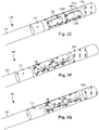
- Figure 1 illustrates one embodiment of a device 100 for brain stimulation.
- the device includes a lead 110, a plurality of electrodes 125 disposed at least partially about a circumference of the lead 110, a plurality of terminals 135, a connector 132 for connection of the electrodes to a control unit, and a stylet 140 for assisting in insertion and positioning of the lead in the patient's brain.
- the stylet 140 is insertable into a stylet lumen (not shown) extending along a longitudinal length of the lead 110.
- the stylet 140 can be made of a rigid material. Examples of suitable materials for the stylet include, but are not limited to, tungsten, stainless steel, and plastic.
- the stylet 140 may have a handle 150 to assist insertion into the lead 110, as well as rotation of the stylet 140 and lead 110.
- the connector 132 fits over a proximal end of the lead 110, preferably after removal of the stylet 140.
- the control unit (not shown) is typically an implantable pulse generator that can be implanted into a patient's body, for example, below the patient's clavicle area.
- the pulse generator can have eight stimulation channels which may be independently programmable to control the magnitude of the current stimulus from each channel. In some cases the pulse generator may have more or fewer than eight stimulation channels (e.g., 4-, 6-, 16-, 32-, or more stimulation channels).
- the control unit may have one, two, three, four, or more connector ports, for receiving the plurality of terminals 135 at the proximal end of the lead 110.
- access to the desired position in the brain can be accomplished by drilling a hole in the patient's skull or cranium with a cranial drill (commonly referred to as a burr), and coagulating and incising the dura mater, or brain covering.
- the lead 110 can be inserted into the cranium and brain tissue with the assistance of the stylet 140.
- the lead 110 can be guided to the target location within the brain using, for example, a stereotactic frame and a microdrive motor system.
- the microdrive motor system can be fully or partially automatic.
- the microdrive motor system may be configured to perform one or more the following actions (alone or in combination): insert the lead 110, retract the lead 110, or rotate the lead 110.
- measurement devices coupled to the muscles or other tissues stimulated by the target neurons, or a unit responsive to the patient or clinician can be coupled to the control unit or microdrive motor system.
- the measurement device, user, or clinician can indicate a response by the target muscles or other tissues to the stimulation or recording electrode(s) to further identify the target neurons and facilitate positioning of the stimulation electrode(s).
- a measurement device can be used to observe the muscle and indicate changes in tremor frequency or amplitude in response to stimulation of neurons.
- the patient or clinician may observe the muscle and provide feedback.
- the lead 110 for deep brain stimulation can include stimulation electrodes, recording electrodes, or both.
- the lead 110 is rotatable so that the stimulation electrodes can be aligned with the target neurons after the neurons have been located using the recording electrodes.
- Stimulation electrodes may be disposed on the circumference of the lead 110 to stimulate the target neurons. Stimulation electrodes may be ring-shaped so that current projects from each electrode equally in every direction from the position of the electrode along a length of the lead 110. Ring electrodes typically do not enable stimulus current to be directed from only a limited angular range around of the lead. Segmented electrodes, however, can be used to direct stimulus current to a selected angular range around the lead. When segmented electrodes are used in conjunction with an implantable pulse generator that delivers constant current stimulus, current steering can be achieved to more precisely deliver the stimulus to a position around an axis of the lead ( i . e ., radial positioning around the axis of the lead).
- segmented electrodes can be utilized in addition to, or as an alternative to, ring electrodes. Though the following description discusses stimulation electrodes, it will be understood that all configurations of the stimulation electrodes discussed may be utilized in arranging recording electrodes as well.
- the lead 100 includes a lead body 110, one or more optional ring electrodes 120, and a plurality of sets of segmented electrodes 130.
- the lead body 110 can be formed of a biocompatible, non-conducting material such as, for example, a polymeric material. Suitable polymeric materials include, but are not limited to, silicone, polyurethane, polyurea, polyurethane-urea, polyethylene, or the like.
- the lead 100 may be in contact with body tissue for extended periods of time.
- the lead 100 has a cross-sectional diameter of no more than 1.5 mm and may be in the range of 0.5 to 1.5 mm.
- the lead 100 has a length of at least 10 cm and the length of the lead 100 may be in the range of 10 to 70 cm.
- the electrodes may be made using a metal, alloy, conductive oxide, or any other suitable conductive biocompatible material.
- suitable materials include, but are not limited to, platinum, platinum iridium alloy, iridium, titanium, tungsten, palladium, palladium rhodium, or the like.
- the electrodes are made of a material that is biocompatible and does not substantially corrode under expected operating conditions in the operating environment for the expected duration of use.
- Each of the electrodes can either be used or unused (OFF).
- the electrode can be used as an anode or cathode and carry anodic or cathodic current.
- an electrode might be an anode for a period of time and a cathode for a period of time.
- Stimulation electrodes in the form of ring electrodes 120 may be disposed on any part of the lead body 110, usually near a distal end of the lead 100.
- the lead 100 includes two ring electrodes 120. Any number of ring electrodes 120 may be disposed along the length of the lead body 110 including, for example, one, two three, four, five, six, seven, eight, nine, ten, eleven, twelve, thirteen, fourteen, fifteen, sixteen or more ring electrodes 120. It will be understood that any number of ring electrodes may be disposed along the length of the lead body 110.
- the ring electrodes 120 are substantially cylindrical and wrap around the entire circumference of the lead body 110.
- the outer diameters of the ring electrodes 120 are substantially equal to the outer diameter of the lead body 110.
- the length of the ring electrodes 120 may vary according to the desired treatment and the location of the target neurons. In some embodiments the length of the ring electrodes 120 are less than or equal to the diameters of the ring electrodes 120. In other embodiments, the lengths of the ring electrodes 120 are greater than the diameters of the ring electrodes 120.
- the distal-most ring electrode 120 may be a tip electrode (see, e.g., tip electrode 320a of Figure 3E ) which covers most, or all, of the distal tip of the lead.
- Deep brain stimulation leads may include one or more sets of segmented electrodes. Segmented electrodes may provide for superior current steering than ring electrodes because target structures in deep brain stimulation are not typically symmetric about the axis of the distal electrode array. Instead, a target may be located on one side of a plane running through the axis of the lead.
- RSEA radially segmented electrode array
- current steering can be performed not only along a length of the lead but also around a circumference of the lead. This provides precise three-dimensional targeting and delivery of the current stimulus to neural target tissue, while potentially avoiding stimulation of other tissue. Examples of leads with segmented electrodes include U.S. Patent Application Publication Nos.
- 2010/0268298 2011/0005069 ; 2011/0130803 ; 2011/0130816 ; 2011/0130817 ; 2011/0130818 ; 2011/0078900 ; 2011/0238129 ; 2012/0016378 ; 2012/0046710 ; 2012/0071949 ; 2012/0165911 ; 2012/197375 ; 2012/0203316 ; 2012/0203320 ; 2012/0203321 , all of which are incorporated herein by reference.
- the lead 100 is shown having a plurality of segmented electrodes 130.
- Any number of segmented electrodes 130 may be disposed on the lead body 110 including, for example, one, two three, four, five, six, seven, eight, nine, ten, eleven, twelve, thirteen, fourteen, fifteen, sixteen or more segmented electrodes 130. It will be understood that any number of segmented electrodes 130 may be disposed along the length of the lead body 110.
- a segmented electrode 130 typically extends only 75%, 67%, 60%, 50%, 40%, 33%, 25%, 20%, 17%, 15%, or less around the circumference of the lead.
- the segmented electrodes 130 may be grouped into sets of segmented electrodes, where each set is disposed around a circumference of the lead 100 at a particular longitudinal portion of the lead 100.
- the lead 100 may have any number segmented electrodes 130 in a given set of segmented electrodes.
- the lead 100 may have one, two, three, four, five, six, seven, eight, or more segmented electrodes 130 in a given set.
- each set of segmented electrodes 130 of the lead 100 contains the same number of segmented electrodes 130.
- the segmented electrodes 130 disposed on the lead 100 may include a different number of electrodes than at least one other set of segmented electrodes 130 disposed on the lead 100.
- the segmented electrodes 130 may vary in size and shape. In some embodiments, the segmented electrodes 130 are all of the same size, shape, diameter, width or area or any combination thereof. In some embodiments, the segmented electrodes 130 of each circumferential set (or even all segmented electrodes disposed on the lead 100) may be identical in size and shape.
- Each set of segmented electrodes 130 may be disposed around the circumference of the lead body 110 to form a substantially cylindrical shape around the lead body 110.
- the spacing between individual electrodes of a given set of the segmented electrodes may be the same, or different from, the spacing between individual electrodes of another set of segmented electrodes on the lead 100.
- equal spaces, gaps or cutouts are disposed between each segmented electrode 130 around the circumference of the lead body 110.
- the spaces, gaps or cutouts between the segmented electrodes 130 may differ in size or shape.
- the spaces, gaps, or cutouts between segmented electrodes 130 may be uniform for a particular set of the segmented electrodes 130, or for all sets of the segmented electrodes 130.
- the sets of segmented electrodes 130 may be positioned in irregular or regular intervals along a length the lead body 110.
- Conductor wires that attach to the ring electrodes 120 or segmented electrodes 130 extend along the lead body 110. These conductor wires may extend through the material of the lead 100 or along one or more lumens defined by the lead 100, or both. The conductor wires are presented at a connector (via terminals) for coupling of the electrodes 120, 130 to a control unit (not shown).
- the ring electrodes 120 and the segmented electrodes 130 may be arranged in any suitable configuration.
- the ring electrodes 120 can flank the two sets of segmented electrodes 130 (see e.g., Figure 1 ).
- the two sets of ring electrodes 120 can be disposed proximal to the two sets of segmented electrodes 130 (see e . g ., Figure 3C ), or the two sets of ring electrodes 120 can be disposed distal to the two sets of segmented electrodes 130 (see e . g ., Figure 3D ).
- One of the ring electrodes can be a tip electrode (see, tip electrode 320a of Figures 3E and 3G ). It will be understood that other configurations are possible as well (e.g., alternating ring and segmented electrodes, or the like).
- the electrode arrangement of Figure 3C may be useful if the physician anticipates that the neural target will be closer to a distal tip of the lead body 110, while the electrode arrangement of Figure 3D may be useful if the physician anticipates that the neural target will be closer to a proximal end of the lead body 110.
- any combination of ring electrodes 120 and segmented electrodes 130 may be disposed on the lead 100.
- the lead may include a first ring electrode 120, two sets of segmented electrodes; each set formed of four segmented electrodes 130, and a final ring electrode 120 at the end of the lead.
- This configuration may simply be referred to as a 1-4-4-1 ( Figures 3A and 3E ) configuration. It may be useful to refer to the electrodes with this shorthand notation.
- the embodiment of Figure 3C may be referred to as a 1-1-4-4 configuration, while the embodiment of Figure 3D may be referred to as a 4-4-1-1 configuration.
- the embodiments of Figures 3F and 3G can be referred to as a 1-3-3-1 configuration.
- Electrodes configurations include, for example, a 2-2-2-2 configuration, where four sets of segmented electrodes are disposed on the lead, and a 4-4 configuration, where two sets of segmented electrodes, each having four segmented electrodes 130 are disposed on the lead.
- the 1-3-3-1 electrode configuration of Figures 3F and 3G has two sets of segmented electrodes, each set containing three electrodes disposed around the circumference of the lead, flanked by two ring electrodes ( Figure 3F ) or a ring electrode and a tip electrode ( Figure 3G ).
- the lead includes 16 electrodes. Possible configurations for a 16-electrode lead include, but are not limited to 4-4-4-4; 8-8; 3-3-3-3-3-1 (and all rearrangements of this configuration); and 2-2-2-2-2-2-2-2.
- Figure 2 is a schematic diagram to illustrate radial current steering along various electrode levels along the length of the lead 200. While conventional lead configurations with ring electrodes are only able to steer current along the length of the lead (the z-axis), the segmented electrode configuration is capable of steering current in the x -axis, y -axis as well as the z -axis. Thus, the centroid of stimulation may be steered in any direction in the three-dimensional space surrounding the lead 200. In some embodiments, the radial distance, r, and the angle ⁇ around the circumference of the lead 200 may be dictated by the percentage of anodic current (recognizing that stimulation predominantly occurs near the cathode, although strong anodes may cause stimulation as well) introduced to each electrode. In at least some embodiments, the configuration of anodes and cathodes along the segmented electrodes allows the centroid of stimulation to be shifted to a variety of different locations along the lead 200.
- the centroid of stimulation can be shifted at each level along the length of the lead 200.
- the use of multiple sets of segmented electrodes at different levels along the length of the lead allows for three-dimensional current steering.
- the sets of segmented electrodes are shifted collectively ( i . e ., the centroid of simulation is similar at each level along the length of the lead).
- each set of segmented electrodes is controlled independently.
- Each set of segmented electrodes may contain two, three, four, five, six, seven, eight or more segmented electrodes. It will be understood that different stimulation profiles may be produced by varying the number of segmented electrodes at each level.
- each set of segmented electrodes includes only two segmented electrodes, uniformly distributed gaps (inability to stimulate selectively) may be formed in the stimulation profile.
- at least three segmented electrodes 230 in a set are utilized to allow for true 360° selectivity.
- measurement devices coupled to the muscles or other tissues stimulated by the target neurons or a unit responsive to the patient or clinician can be coupled to the control unit or microdrive motor system.
- the measurement device, user, or clinician can indicate a response by the target muscles or other tissues to the stimulation or recording electrodes to further identify the target neurons and facilitate positioning of the stimulation electrodes.
- a measurement device can be used to observe the muscle and indicate changes in tremor frequency or amplitude in response to stimulation of neurons.
- the patient or clinician may observe the muscle and provide feedback.
- the lead 100 when the lead 100 includes a plurality of sets of segmented electrodes 130, it may be desirable to form the lead 100 such that corresponding electrodes of different sets of segmented electrodes 130 are radially aligned with one another along the length of the lead 100 (see e . g ., the segmented electrodes 130 shown in Figure 1 ). Radial alignment between corresponding electrodes of different sets of segmented electrodes 130 along the length of the lead 100 may reduce uncertainty as to the location or orientation between corresponding segmented electrodes of different sets of segmented electrodes. Accordingly, it may be beneficial to form electrode arrays such that corresponding electrodes of different sets of segmented electrodes along the length of the lead 100 are radially aligned with one another and do not radially shift in relation to one another during manufacturing of the lead 100.
- individual electrodes in the two sets of segmented electrodes 130 are staggered (see, Figure 3B ) relative to one another along the length of the lead body 110.
- the staggered positioning of corresponding electrodes of different sets of segmented electrodes along the length of the lead 100 may be designed for a specific application.
- Segmented electrodes can be used to tailor the stimulation region so that, instead of stimulating tissue around the circumference of the lead as would be achieved using a ring electrode, the stimulation region can be directionally targeted. In some instances, it is desirable to target a parallelepiped (or slab) region 250 that contains the electrodes of the lead 200, as illustrated in Figure 2 .
- One arrangement for directing a stimulation field into a parallelepiped region uses segmented electrodes disposed on opposite sides of a lead.
- Figures 3A-3G illustrate leads 300 with segmented electrodes 330, optional ring electrodes 320 or tip electrodes 320a, and a lead body 310.
- the sets of segmented electrodes 330 include either two ( Figure 3B ), three ( Figures 3F and 3G ), or four ( Figures 3A, 3C, and 3D ) or any other number of segmented electrodes including, for example, five, six, or more.
- segmented electrodes can be used.
- One embodiment includes a double helix.
- Sets of radially-disposed segmented electrodes can be formed from pre-electrodes.
- At least some conventional pre-electrodes include stimulation members coupled to one another by connecting material disposed along a periphery of the pre-electrodes.
- Formation of the segmented electrodes from such conventional pre-electrodes may include grinding down the connecting material disposed along the periphery of the pre-electrodes to physically separate the stimulation members from one another and form electrically-isolated segmented electrodes.
- a pre-electrode includes stimulation members coupled to one another via a central hub that can be removed during manufacture to physically separate the stimulation members from one another and form electrically-isolated segmented electrodes.
- each of the stimulation members is electrically-coupled to each of the remaining stimulation members solely via the central hub.
- the pre-electrode does not include connecting material that is disposed along a periphery of the pre-electrode and that couples together adjacent stimulation members. Thus, electrical isolation between the stimulation members may result solely by removal of the central hub.
- the pre-electrodes described herein, as well as the segmented electrodes formed therefrom, may be formed of an electrical conductor such as a metal, alloy, conductive oxide, or any other suitable conductive material.
- the pre-electrodes are formed of platinum, platinum-iridium, iridium, 616L stainless steel (or any other suitable stainless steel), tantalum, Nitinol, iridium rhodium, or a conductive polymer.
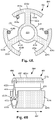
- Figure 4A schematically illustrates, in transverse cross-section, one embodiment of a pre-electrode 400 suitable for use in forming a set of radially-disposed segmented electrodes.
- Figure 4B schematically illustrates one embodiment of the pre-electrode 400 in perspective view.
- the pre-electrode 400 includes a body 402 having a proximal end 404, a distal end 406, and a longitudinal length 408.
- the body 402 includes a central hub 414 with a longitudinal surface 424.
- Stimulation members 418a, 418b, and 418c are coupled to the central hub 414 via connector elements 422a, 422b, and 422c, respectively, extending radially from the longitudinal surface 424 of the central hub 414.
- the stimulation members 418a, 418b, and 418c are each shown coupled to the central hub 414 by a single connector element 422a, 422b, or 422c.
- at least one of the stimulation members 418a, 418b, and 418c is coupled to the central hub 414 by multiple connector elements 422a, 422b, or 422c.
- the central hub 414 can be any suitable shape and shape.
- the central hub 414 is shown as being tube-shaped with a hub aperture 416. It may be beneficial to form the central hub 414 as tube-shaped, or substantially tube-shaped, so that when electrically-nonconductive material is disposed about the longitudinal surface 424 of the central hub 414 (see e.g., Figure 9A ) and the central hub 414 is removed ( see e .
- the central lumen formed at the location formerly occupied by the central hub 414 is similar in size and shape to the axially-disposed stylet lumen (not shown) that extends along the longitudinal length of the lead and that receives the stylet (140 in Figure 1 ) during implantation of the lead.
- the connector elements 422a, 422b, and 422c can extend along the entire longitudinal length 408 of the body 402, or only a portion of the longitudinal length 408. In at least some embodiments, the connector elements 422a, 422b, and 422c are coupled to the longitudinal surface 424 of the central hub 414 such that the connector elements 422a, 422b, and 422c are equally spaced around a circumference of the central hub 414. For example, in Figure 4A three connector elements 422a, 422b, and 422c are shown as each being 120° apart from the remaining two connector elements around a circumference of the central hub 414. As another example, in Figure 8 four connector elements 822a, 822b, 822c, and 822d are shown as each being 90° apart from the adjacent two connector elements around a circumference of the central hub 814.
- the body 402 of the pre-electrode 400 can be any suitable shape.
- the body 402 is substantially cylindrical, with the stimulation members 418a, 418b, and 418c forming an outer periphery of the body 402.
- the outer surfaces 426a, 426b, and 426c of the stimulation members 418a, 418b, and 418c form the outer surfaces of the segmented electrodes (see e.g., Figure 9C ) during operation of the segmented electrodes.
- the outer surfaces 426a, 426b, and 426c of the stimulation members 418a, 418b, and 418c are ground down prior to operation as electrically-isolated segmented electrodes.
- the body 402 of the pre-electrode 400 can be any suitable size.
- the body 402 has a diameter that is equal, or substantially equal, to a diameter of the distal end portion of the lead (see e.g., 110 in Figure 1 ) onto which the pre-electrode is to be disposed.
- the stimulation members 418a, 418b, and 418c can extend along the entire longitudinal length 408 of the body 402, or only a portion of the longitudinal length 408.
- the stimulation members 418a, 418b, and 418c each include outer surfaces 426a, 426b, and 426c, respectively, and inner surfaces 428a, 428b, and 428c, respectively.
- the connector elements 422a, 422b, and 422c couple to the stimulation members 418a, 418b, and 418c, respectively, along the inner surfaces 428a, 428b, and 428c of the stimulation members 418a, 418b, and 418c, respectively.
- the outer surfaces 426a, 426b, and 426c of the stimulation members 418a, 418b, and 418c can be any suitable shape.
- the stimulation members 418a, 418b, and 418c are arcuate with the outer surfaces 426a, 426b, and 426c being convex and the inner surfaces 428a, 428b, and 428c being concave.
- the stimulation members 418a, 418b, and 418c are arced such that the outer surfaces 426a, 426b, and 426c are similarly arced as a transverse cross-section of the lead (see e.g., 952 in Figures 9B and 9C ) onto which the pre-electrode is to be disposed.
- Stimulation energy passed through the segmented electrodes (see e.g., 918a, 918b, and 918c of Figures 9B and 9C ) formed from the pre-electrode 400 is typically provided to the segmented electrodes via conductors, such as conductors 430a, 430b, and 430c.
- the conductors 430a, 430b, and 430c can be coupled either: to the stimulation members 418a, 418b, and 418c of the pre-electrode 400; or to the segmented electrodes ( see e . g ., 918a, 918b, and 918c of Figures 9B and 9C ) formed from the stimulation members 418a, 418b, and 418c.
- the conductors 430a, 430b, and 430c are shown coupled to the inner surfaces 428a, 428b, and 428c of the stimulation members 418a, 418b, and 418c, respectively.
- one or more of the conductors 430a, 430b, and 430c can be coupled to one or more of the connector elements 422a, 422b, and 422c, respectively, in lieu of or in addition to the inner surfaces 428a, 428b, and 428c of the stimulation members 418a, 418b, and 418c, respectively.
- an electrically-nonconductive material is disposed about the longitudinal surface of the central hub.
- the electrically-nonconductive material extends radially-outward from the central hub to the stimulation members such that the inner surfaces of the stimulation members are encased in the electrically-nonconductive material.
- the electrically-nonconductive material extends radially-outward from the central hub to the stimulation members such the outer (longitudinal) surface of the electrically-nonconductive material is flush with the outer surfaces of the stimulation members.
- the electrically-nonconductive material can be disposed over the longitudinal surface of the central hub in any suitable manner including, for example, injection molding, re-flowing polymeric material, or the like.
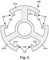
- the pre-electrode may, optionally, include one or more lead-retention features disposed along one or more of the stimulation members 418a, 418b, and 418c, one or more of the connector elements 422a, 422b, and 422c, or both.
- the one or more lead-retention features may be used to promote adhesion of the electrically-nonconductive material to the pre-electrode (and to the segmented electrodes formed therefrom).
- the one or more lead-retention features in addition to promoting adhesion of the segmented electrodes to the electrically-nonconductive material, may also facilitate maintaining relative positioning and the physical separation (and electrical isolation) between the segmented electrodes.
- FIG. 5 schematically illustrates, in transverse cross-section, one embodiment of lead-retention features 502 disposed along the pre-electrode 400.
- the lead-retention features 502 are formed as barbs 506 extending from the inner surfaces 428a, 428b, and 428c of the stimulation members 418a, 418b, and 418c, respectively.
- the barbs 506 can be disposed along any suitable portion of the inner surfaces 428a, 428b, and 428c of the stimulation members 418a, 418b, and 418c.
- the barbs 506 are shown extending from opposing ends of the inner surfaces 428a, 428b, and 428c of the stimulation members 418a, 418b, and 418c.
- the barbs 506 can be formed from either the same material or from different material as the stimulation members 418a, 418b, and 418c.
- any suitable number of barbs 506 can be disposed on the pre-electrode 400 including, for example, one, two, three, four, five, six, seven, eight, nine, ten, eleven, twelve, fifteen, or more barbs 506.
- at least one barb 506 is disposed on each of the stimulation members 418a, 418b, and 418c.
- at least two barbs 506 are disposed on each of the stimulation members 418a, 418b, and 418c.
- an equal number of barbs 506 are disposed on each of the stimulation members 418a, 418b, and 418c.
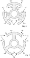
- Figure 6 schematically illustrates, in transverse cross-section, another embodiment of lead-retention features 602 disposed along the pre-electrode 400.
- the lead-retention features 602 are formed as barbs 606 extending from the connector elements 422a, 422b, and 422c.
- the barbs 606 can be disposed along any suitable portion of the connector elements 422a, 422b, and 422c.
- the barbs 606 are shown extending from opposing sides of the connector elements 422a, 422b, and 422c along a length of the connector elements 422a, 422b, and 422c.
- the barbs 606 can be formed from either the same material or from different material as the connector elements 422a, 422b, and 422c.
- any suitable number of barbs 606 can be disposed on the pre-electrode 400 including, for example, one, two, three, four, five, six, seven, eight, nine, ten, eleven, twelve, fifteen, or more barbs 606.
- at least one barb 606 is disposed on each of the connector elements 422a, 422b, and 422c.
- at least two barbs 606 are disposed on each of the connector elements 422a, 422b, and 422c.
- at least one barb 606 is disposed on each side of each of the connector elements 422a, 422b, and 422c.
- an equal number of barbs 606 are disposed on each of the connector elements 422a, 422b, and 422c.
- Figure 7 schematically illustrates, in transverse cross-section, one embodiment of lead-retention features 702 disposed along the pre-electrode 400.
- the lead-retention features 702 are formed as undercuts 706 formed along at least one longitudinal edge of the stimulation members 418a, 418b, and 418c.
- the undercuts 706 are shown formed along opposing ends of the stimulation members 418a, 418b, and 418c.
- undercuts 706 can be disposed on the pre-electrode 400 including, for example, one, two, three, four, five, six, or more undercuts 706. In at least some embodiments, at least one undercut 706 is disposed on each of the stimulation members 418a, 418b, and 418c. In at least some embodiments, at least two undercuts 706 are disposed on each of the stimulation members 418a, 418b, and 418c. In at least some embodiments, an equal number of undercuts 706 are disposed on each of the stimulation members 418a, 418b, and 418c.
- a pre-electrode may have undercuts and barbs (either disposed along one or more of the stimulation members or disposed along one or more of the connector elements).
- a pre-electrode may have no undercuts but may have barbs disposed along both the stimulation members and the one or more of the connector elements.
- the pre-electrode is shown having three stimulation members. It will be recognized that the pre-electrode may include any suitable number of stimulation members including, for example, two, three, four, five, six, seven, eight, or more stimulation members.
- Figure 8 schematically illustrates, in transverse cross-section, one embodiment of the pre-electrode 400 with a body 802 having four stimulation members 818a, 818b, 818c, and 818d.
- the body 802 includes a central hub 814 with a longitudinal surface 824.
- the stimulation members 818a, 818b, 818c, and 818d are coupled to the central hub 814 via connector elements 822a, 822b, 822c, and 822d, respectively, extending radially from the longitudinal surface 824 of the central hub 814.
- the stimulation members 818a, 818b, 818c, and 818d are each shown coupled to the central hub 414 by a single connector element 822a, 822b, 822c, and 822d.
- at least one of the stimulation members 818a, 818b, 818c, and 818d is coupled to the central hub 814 by multiple connector elements 822a, 822b, 822c, and 822d.
- the pre-electrodes are typically disposed along a distal end portion of the lead and the central hubs removed to electrically-isolate each of the stimulation members (and their attached connector elements) from one another, thereby forming segmented electrodes.
- the pre-electrode of Figure 5 is shown in each of Figures 9A-9C . It will be understood that the techniques for disposing pre-electrodes on leads and for electrically-isolating the stimulation members (and their attached connector elements) to form segmented electrodes are applicable for each of the pre-electrodes described herein.
- Figure 9A schematically illustrates, in transverse cross-section, one embodiment of electrically-nonconductive material 902 disposed radially about the central hub 414 of the pre-electrode 400.
- the electrically-nonconductive material 902 encases the longitudinal surfaces 424 of the central hub 414 and the connector elements 422a, 422b, and 422c. Additionally, the electrically-nonconductive material 902 abuts the inner surfaces 428a, 428b, and 428c of the stimulation members 418a, 418b, and 418c, respectively.
- the electrically-nonconductive material 902 is disposed about the central hub 414 so that the outer surfaces 426a, 426b, and 426c of the stimulation members 418a, 418b, and 418c, respectively, are flush, or approximately flush, with longitudinal surface 954 of the electrically-nonconductive material 902.
- the electrically-nonconductive material is a polymeric material. In at least some embodiments, the electrically-nonconductive material is the same material (or similar material) to the material used to form the lead body (e.g., polyurethane, silicone, adhesive, or the like or combinations thereof).
- the electrically-nonconductive material 902 can be disposed over the longitudinal surface 424 of the central hub 414 in any suitable manner including, for example, injection molding, re-flowing, or the like.
- Figure 9A shows the conductors 430a, 430b, and 430c coupled to stimulation members 418a, 418b, and 418c, respectively.
- the conductors 430a, 430b, and 430c can be coupled to stimulation members 418a, 418b, and 418c (or to attached connector elements), either before or after the electrically-nonconductive material is disposed around the central hub 414.
- the pre-electrode can be attached to the end of a lead body in any suitable manner including, for example, re-flowing the electrically-nonconductive material, re-flowing the material of the lead body (or both), re-flowing both the electrically-nonconductive material and the material of the lead body, applying an adhesive, or the like or combinations thereof.
- the lead body can be formed simultaneously with the formation of the segmented electrodes so that the lead body and the electrically-nonconductive material disposed about the central hub are formed as a single structure.
- the lead may include multiple sets of segmented electrodes (or ring or tip electrodes). In which case, multiple pre-electrodes may be arranged in a desired axial configuration with electrically-nonconductive material disposed axially between axially-adjacent pre-electrodes (or ring or tip electrodes).
- the central hub may be removed. Once the central hub of the pre-electrode is removed, the remaining electrically-isolated stimulation members, and their corresponding connector elements, are referred to as segmented electrodes. The removal of the central hub may additionally remove at least a portion of at least one of the connector elements.
- Figure 9B schematically illustrates, in transverse cross-section, one embodiment of a distal end portion of a lead 952.
- the lead 952 includes the electrically-nonconductive material 902 and segmented electrodes 918a, 918b, and 918c formed from the pre-electrode 400 by the removal of the central hub 414 of the pre-electrode 400. Removal of the central hub 414 causes a central lumen 940 to be formed in the electrically-nonconductive material 902 at the location along the lead 952 where the central hub 414 was positioned prior to being removed.
- Removal of the central hub 414 can be performed in any suitable manner.
- the central hub 414 is bored out (e.g., drilled out, or the like).
- a drill may be passed through a portion of the lead 952 that includes the central hub 414.
- the drill is passed through a distal tip of the lead 952 and extended through the longitudinal length (408 in Figure 4B ) of the pre-electrode. Boring out the central hub 414 in such a manner may form the central lumen 940 along the distal end portion of the lead, in addition to the space formerly occupied by the central hub 414.
- the distal tip may be subsequently capped or a tip electrode may subsequently be disposed along the distal tip.
- the lead body includes a stylet lumen for receiving the stylet (140 in Figure 1 ).
- the pre-electrode may be disposed on the lead body such that the central hub 414 is axially aligned with, and open to, the stylet lumen.
- Such an arrangement may enable the stylet to be introduced into the central lumen 940 during implantation.
- the drill may, in at least some embodiments, be passed along at least a portion of the stylet lumen.
- one or more portions of the segmented electrodes may be physically exposed to the central lumen 940. It may be desirable to avoid having portions of the segmented electrode be physically exposed to the central lumen 940 to prevent potential undesired short-circuiting caused by, for example, bodily fluids seeping into the central lumen over time during operation).
- an insulating material is disposed between the body of the lead and the central lumen 940 at the distal end portion of the lead body. The insulating material is electrically-nonconductive and functions to electrically-isolate the segmented electrodes from the central lumen 940.
- FIG 9C schematically illustrates, in transverse cross-section, one embodiment of the distal end portion of the lead 952.
- the lead 952 includes the central lumen 940 and segmented electrodes 918a, 918b, and 918c formed from the pre-electrode 400.
- the segmented electrodes 918a, 918b, and 918c shown in Figure 9C include the stimulation members 418a, 418b, and 418c, and the attached connector elements 422a, 422b, and 422c of the pre-electrode 400.
- the stimulation members 418a, 418b, and 418c include outer surfaces 426a, 426b, and 426c and opposing inner surfaces 428a, 428b, and 428c (as shown in Figure 9A ).
- the outer surfaces 426a, 426b, and 426c of the segmented electrodes 918a, 918b, and 918c, respectively, are exposed along a longitudinal surface 954 of the electrically-nonconductive material 902.
- the outer surfaces 426a, 426b, and 426c of the segmented electrodes 918a, 918b, and 918c and/or the longitudinal surface 954 of the electrically-nonconductive material 902 may be ground down so that the outer surfaces 426a, 426b, and 426c of the segmented electrodes 918a, 918b, and 918c and the longitudinal surface 954 of the electrically-nonconductive material 902 are flush with one another.
- the connector-element portions of the segmented electrodes each extend along at least 20%, 30%, 40%, 50%, 60%, 70%, or more of a radius of the lead.
- the connector-element portions of the segmented electrodes may be physically exposed to the central lumen 940.
- insulating material 960 is disposed along at least a portion of the longitudinal walls of the central lumen 940 to electrically-isolate the segmented electrodes 918a, 918b, and 918c from the central lumen 940. In at least some embodiments, when the insulating material 960 is disposed along at least a portion of the longitudinal walls of the central lumen 940 the connector-element portions of the segmented electrodes 918a, 918b, and 918c physically abut the insulating material 960.
- the insulating material 960 can be formed from any suitable electrically-nonconductive material including, for example, polyurethane, silicone, adhesive, or the like or combinations thereof. In at least some embodiments, the insulating material 960 is formed from a different material from the electrically-nonconductive material 902. In at least some embodiments, the insulating material 960 is formed from a different material from the electrically-nonconductive material used to form the lead body. In at least some embodiments, the insulating material 960 is formed from a different material from the electrically-nonconductive material 902 or the material used to form the lead body.
- the insulating material 960 can be applied to the longitudinal walls of the central lumen 940 using any suitable technique.
- the insulating material 960 is formed as a liner that is inserted into the central lumen 940 and re-flowed with the walls of the central lumen 940.
- Other techniques for applying the insulating material 960 may include, for example, injection molding, chemical vapor deposition, or the like.
Landscapes
- Health & Medical Sciences (AREA)
- Neurology (AREA)
- Neurosurgery (AREA)
- Psychology (AREA)
- Cardiology (AREA)
- Heart & Thoracic Surgery (AREA)
- Engineering & Computer Science (AREA)
- Biomedical Technology (AREA)
- Nuclear Medicine, Radiotherapy & Molecular Imaging (AREA)
- Radiology & Medical Imaging (AREA)
- Life Sciences & Earth Sciences (AREA)
- Animal Behavior & Ethology (AREA)
- General Health & Medical Sciences (AREA)
- Public Health (AREA)
- Veterinary Medicine (AREA)
- Electrotherapy Devices (AREA)
Claims (15)
- Verfahren zum Herstellen einer Stimulationsleitung (100; 200; 300), wobei das Verfahren aufweist:Anordnen mindestens einer Vorelektrode (400) entlang einem distalen Endabschnitt eines Leitungskörpers (110; 310), wobei die mindestens eine Vorelektrode (400) einen Vorelektrodenkörper (402) mit einem proximalen Ende (404) und einem distalen Ende (406) aufweist und der Vorelektrodenkörper (402) aufweist:eine elektrisch leitende Mittelnabe (414; 814),mehrere elektrisch leitende Stimulationselemente (418a; 418b; 418c; 818a; 818b;818c), die einzeln mit der Mittelnabe (414; 814) gekoppelt sind und sich von ihr radial nach außen erstrecken, so dass jedes der elektrisch leitenden Stimulationselemente (418a; 418b; 418c; 818a; 818b; 818c) mit jedem der übrigen Stimulationselemente (418a; 418b; 418c; 818a; 818b; 818c) allein über die Mittelnabe (414; 814) elektrisch gekoppelt ist;elektrisches Koppeln mindestens eines Leiters von mehreren Leitern (430a; 430b;430c), die sich aus mehreren, entlang dem proximalen Endabschnitt des Leitungskörpers (110; 310) angeordneten Anschlüssen (135) erstrecken, mit jedem der mehreren Stimulationselemente (418a; 418b; 418c; 818a; 818b; 818c);Anordnen von elektrisch nichtleitendem Material (902) um Längsflächen (424; 824) der Mittelnabe (414; 814), wobei das elektrisch nichtleitende Material (902) an Innenflächen (428a; 428b; 428c) der mehreren Stimulationselemente (418a; 418b; 418c; 818a; 818b; 818c) anliegt; undEntfernen der Mittelnabe (414; 814) von dem Vorelektrodenkörper (402), um jedes der mehreren Stimulationselemente (418a; 418b; 418c; 818a; 818b; 818c) voneinander elektrisch zu isolieren, wodurch die mehreren Stimulationselemente (418a; 418b; 418c; 818a; 818b; 818c) in mehrere elektrisch isolierte segmentierte Elektroden (918; 918b; 918c) umgewandelt werden, die entlang dem elektrisch nichtleitenden Material (902) angeordnet sind.
- Verfahren nach Anspruch 1, wobei das Anordnen mindestens einer Vorelektrode (400) entlang einem distalen Endabschnitt eines Leitungskörpers (110, 310) das Anordnen mindestens einer Vorelektrode (400) entlang dem distalen Endabschnitt des Leitungskörpers (110; 310) aufweist, die mehrere Verbindungselemente (422a; 422b; 422c; 822a; 822b; 822c) aufweist, welche die mehreren Stimulationselemente (418a; 418b; 418c; 818a; 818b; 818c) elektrisch mit der Mittelnabe (414; 814) koppeln.
- Verfahren nach Anspruch 1, wobei das Anordnen mindestens einer Vorelektrode (400) entlang einem distalen Endabschnitt eines Leitungskörpers (110, 310) das Anordnen mindestens einer Vorelektrode (400) entlang dem distalen Endabschnitt des Leitungskörpers (110; 310) aufweist, die genau drei elektrisch leitende Stimulationselemente (418a; 418b; 418c; 818a; 818b; 818c) aufweist.
- Verfahren nach Anspruch 1, wobei das Entfernen der Mittelnabe (414; 814) zum elektrischen Isolieren der mehreren Stimulationselemente (418a; 418b; 418c; 818a; 818b; 818c) voneinander das Hindurchführen eines Bohrers durch einen Abschnitt des Leitungskörpers (110; 310), der die Mittelnabe (414; 814) einschließt, aufweist, um die Mittelnabe zu entfernen und Verbindungen zwischen den mehreren Verbindungselementen (422a; 422b; 422c; 822a; 822b; 822c) zu trennen, wobei das Hindurchführen des Bohrers ein zentrales Lumen (940) durch mindestens einen Abschnitt des Leitungskörpers (110; 310) ausbildet.
- Verfahren nach Anspruch 1, das ferner das Anordnen von Isoliermaterial (960) an Wänden des zentralen Lumens (940) aufweist, um die segmentierten Elektroden (918; 918b; 918c) vom zentralen Lumen (940) elektrisch zu isolieren.
- Verfahren nach Anspruch 5, wobei das Anordnen von Isoliermaterial (960) an Wänden des zentralen Lumens (940) das Wiederaufschmelzen von elektrisch nichtleitenden Rohren entlang den Wänden des zentralen Lumens (940) aufweist.
- Verfahren nach Anspruch 5, wobei das Anordnen von Isoliermaterial (960) an Wänden des zentralen Lumens (940) das Aufbringen von elektrisch nichtleitendem Material (902) durch chemische Dampfabscheidung entlang den Wänden des zentralen Lumens (940) aufweist.
- Verfahren nach Anspruch 5, wobei das Anordnen von Isoliermaterial (960) an Wänden des zentralen Lumens (940) das Spritzgießen von elektrisch nichtleitendem Material (902) entlang den Wänden des zentralen Lumens (940) aufweist.
- Verfahren nach Anspruch 1, wobei das Anordnen von elektrisch nichtleitendem Material (902) um Längsflächen (424; 824) der Mittelnabe (414; 814) herum, wobei das elektrisch nichtleitende Material (902) an Innenflächen (428a; 428b; 428c) der mehreren Stimulationselemente (418a; 418b; 418c; 818a; 818b; 818c) anliegt, das Anordnen von elektrisch nichtleitendem Material (902) um Längsflächen (424; 824) der Mittelnabe (414; 814) herum aufweist, wobei das elektrisch nichtleitende Material (902) bündig mit Außenflächen (426a; 426b; 426c) der mehreren Stimulationselemente (418a; 418b; 418c; 818a; 818b; 818c) abschließt.
- Vorelektrode (400) für eine Stimulationsleitung (100; 200; 300), wobei die Vorelektrode (400) aufweist:
einen im Wesentlichen zylindrischen Vorelektrodenkörper (402) mit einem proximalen Ende (404) und einem distalen Ende (406), wobei der Vorelektrodenkörper (402) aufweist:eine elektrisch leitende Mittelnabe (414; 814), mit einer Längsfläche (424; 824),mehrere Verbindungselemente (422a; 422b; 422c; 822a; 822b; 822c), die sich von der Längsfläche (424; 824) der Mittelnabe (414; 814) radial nach außen erstrecken, wobei die mehreren Verbindungselemente (422a; 422b; 422c; 822a; 822b; 822c) jeweils ein mit der Mittelnabe (414; 814) gekoppeltes mediales Ende und ein gegenüberliegendes laterales Ende aufweisen, undmehrere Stimulationselemente (418a; 418b; 418c; 818a; 818b; 818c), die jeweils eine Innenfläche (428a; 428b; 428c) und eine Außenfläche (426a; 426b; 426c) aufweisen, wobei die Innenfläche (428a; 428b; 428c) jedes der mehreren Stimulationselemente (418a; 418b; 418c; 818a; 818b; 818c) so mit dem medialen Ende mindestens eines der mehreren Verbindungselemente (422a; 422b; 422c; 822a; 822b; 822c) gekoppelt ist, dass jedes der mehreren Stimulationselemente (418a; 418b; 418c; 818a; 818b; 818c) allein über die Mittelnabe (414; 814) mit jedem der übrigen Stimulationselemente (418a; 418b; 418c; 818a; 818b; 818c) der mehreren Stimulationselemente (418a; 418b; 418c; 818a; 818b; 818c) elektrisch gekoppelt ist. - Vorelektrode (400) nach Anspruch 10, wobei die Mittelnabe (414; 814) röhrenförmig ist.
- Vorelektrode (400) nach Anspruch 10, wobei die Innenfläche (428a; 428b; 428c) jedes der mehreren Stimulationselemente (418a; 418b; 418c; 818a; 818b; 818c) mit dem medialen Ende genau eines der mehreren Verbindungselemente (422a; 422b; 422c; 822a; 822b; 822c) gekoppelt ist.
- Stimulationsleitung (100; 200; 300), aufweisend:einen Leitungskörper (110; 310; 952), der eine Längsfläche (954), einen distalen Endabschnitt, einen proximalen Endabschnitt und eine Längserstreckung (408) aufweist, wobei der Leitungskörper (110; 310; 952) aus einem Leitungskörpermaterial gebildet ist;ein zentrales Lumen (940), das sich entlang der Längserstreckung des Leitungskörpers (110; 310; 952) erstreckt, wobei das zentrale Lumen (940) durch Längswände begrenzt ist;Isoliermaterial (960), das am distalen Endabschnitt des Leitungskörpers (110; 310; 952) zwischen dem Leitungskörper (110; 310; 952) und dem zentralen Lumen (940) angeordnet ist, wobei das Isoliermaterial (960) elektrisch nichtleitend und ein vom Leitkörpermaterial verschiedenes Material ist;mehrere Anschlüsse (135), die entlang dem proximalen Endabschnitt des Leitungskörpers (110; 310; 952) angeordnet sind;mehrere Elektroden (125), die entlang dem distalen Endabschnitt des Leitungskörpers (110; 310; 952) angeordnet sind, wobei die mehreren Elektroden (125) mehrere segmentierte Elektroden (330; 918a; 918b; 918c) aufweisen und jede der mehreren segmentierten Elektroden (330; 918a; 918b; 918c) von den anderen elektrisch isoliert ist, undein elektrisch leitendes Stimulationselement (418a; 418b; 418c; 818a; 818b; 818c) mit einer Außenfläche (426a; 426b; 426c) und einer gegenüberliegenden Innenfläche (428a; 428b; 428c) undein Verbindungselement (422a; 422b; 422c; 822a; 822b; 822c) aufweist, das mit der Innenfläche (428a; 428b; 428c) des Stimulationselements (418a; 418b; 418c; 818a; 818b; 818c) gekoppelt ist und sich radial nach innen zum Isoliermaterial (960) erstreckt, wobei das Verbindungselement physisch am Isoliermaterial (960) anliegt undmehrere Leiter (430a; 430b; 430c), die die mehreren Anschlüsse (135) mit den mehreren Elektroden (125) elektrisch koppeln.
- Stimulationsleitung (100; 200; 300) nach Anspruch 13, wobei das Stimulationselement (418a; 418b; 418c; 818a; 818b; 818c) mindestens einer der mehreren segmentierten Elektroden (330; 918a; 918b; 918c) ferner mindestens ein Leitungsrückhaltemerkmal (502; 602; 702) aufweist.
- Stimulationsleitung nach Anspruch 14, wobei das mindestens eine Leitungsrückhaltemerkmal (502; 602; 702) eines der folgenden aufweist: a) mindestens einen Widerhaken (506), der an der Innenfläche (428a; 428b; 428c) des Stimulationselements (418a; 418b; 418c; 818a; 818b; 818c) der segmentierten Elektrode (330; 918a; 918b; 918c) angeordnet ist; b) mindestens einen Widerhaken (606), der entlang dem Verbindungselement (422a; 422b; 422c) der segmentierten Elektrode (330; 918a; 918b; 918c) angeordnet ist; oder c) mindestens eine Hinterschneidung (706), die entlang dem Stimulationselement (418a; 418b; 418c; 818a; 818b; 818c) der segmentierten Elektrode (330; 918a; 918b; 918c) angeformt ist.
Applications Claiming Priority (2)
| Application Number | Priority Date | Filing Date | Title |
|---|---|---|---|
| US201361845739P | 2013-07-12 | 2013-07-12 | |
| PCT/US2014/045618 WO2015006239A1 (en) | 2013-07-12 | 2014-07-07 | Leads with segmented electrodes and methods of making and using the leads |
Publications (2)
| Publication Number | Publication Date |
|---|---|
| EP3019232A1 EP3019232A1 (de) | 2016-05-18 |
| EP3019232B1 true EP3019232B1 (de) | 2019-08-21 |
Family
ID=51230206
Family Applications (1)
| Application Number | Title | Priority Date | Filing Date |
|---|---|---|---|
| EP14744704.9A Active EP3019232B1 (de) | 2013-07-12 | 2014-07-07 | Leitungen mit segmentierten elektroden und verfahren zur herstellung der leitungen |
Country Status (6)
| Country | Link |
|---|---|
| US (1) | US9289596B2 (de) |
| EP (1) | EP3019232B1 (de) |
| JP (1) | JP6072986B2 (de) |
| CN (1) | CN105377360A (de) |
| AU (1) | AU2014287516A1 (de) |
| WO (1) | WO2015006239A1 (de) |
Families Citing this family (137)
| Publication number | Priority date | Publication date | Assignee | Title |
|---|---|---|---|---|
| US7860570B2 (en) | 2002-06-20 | 2010-12-28 | Boston Scientific Neuromodulation Corporation | Implantable microstimulators and methods for unidirectional propagation of action potentials |
| US8321025B2 (en) | 2006-07-31 | 2012-11-27 | Cranial Medical Systems, Inc. | Lead and methods for brain monitoring and modulation |
| EP2644227B1 (de) | 2008-07-30 | 2016-12-28 | Ecole Polytechnique Fédérale de Lausanne | Vorrichtung zur optimierten Stimulierung eines neurologischen Ziels |
| CA2743575C (en) | 2008-11-12 | 2017-01-31 | Ecole Polytechnique Federale De Lausanne | Microfabricated neurostimulation device |
| EP2552536B1 (de) | 2010-04-01 | 2016-06-08 | Ecole Polytechnique Fédérale de Lausanne (EPFL) | Vorrichtung zur interaktion mit nervengewebe |
| US9919148B2 (en) | 2012-05-25 | 2018-03-20 | Boston Scientific Neuromodulation Corporation | Distally curved electrical stimulation lead and methods of making and using |
| JP2016512758A (ja) | 2013-03-15 | 2016-05-09 | ボストン サイエンティフィック ニューロモデュレイション コーポレイション | 閾値以下の治療を患者に提供するシステム及び方法 |
| US9162048B2 (en) | 2013-05-15 | 2015-10-20 | Boston Scientific Neuromodulation Corporation | Systems and methods for making and using tip electrodes for leads of electrical stimulation systems |
| EP3077039B1 (de) | 2013-12-02 | 2021-10-13 | Boston Scientific Neuromodulation Corporation | Verfahren zur herstellung von elektrischen stimulationsleitungen mit spiralförmig angeordneten elektroden |
| US11311718B2 (en) | 2014-05-16 | 2022-04-26 | Aleva Neurotherapeutics Sa | Device for interacting with neurological tissue and methods of making and using the same |
| WO2015173787A1 (en) | 2014-05-16 | 2015-11-19 | Aleva Neurotherapeutics Sa | Device for interacting with neurological tissue and methods of making and using the same |
| WO2015192058A1 (en) | 2014-06-13 | 2015-12-17 | Boston Scientific Neuromodulation Corporation | Leads with electrode carriers for segmented electrodes and methods of making and using |
| US9474894B2 (en) | 2014-08-27 | 2016-10-25 | Aleva Neurotherapeutics | Deep brain stimulation lead |
| US9770598B2 (en) | 2014-08-29 | 2017-09-26 | Boston Scientific Neuromodulation Corporation | Systems and methods for making and using improved connector contacts for electrical stimulation systems |
| PT3193696T (pt) | 2014-09-17 | 2021-02-04 | Richard M Levitan | Dispositivo de introdução para intubação de tubo traqueal |
| US9974959B2 (en) | 2014-10-07 | 2018-05-22 | Boston Scientific Neuromodulation Corporation | Systems, devices, and methods for electrical stimulation using feedback to adjust stimulation parameters |
| US9604068B2 (en) | 2014-11-10 | 2017-03-28 | Boston Scientific Neuromodulation Corporation | Systems and methods for making and using improved connector contacts for electrical stimulation systems |
| US9561362B2 (en) | 2014-11-10 | 2017-02-07 | Boston Scientific Neuromodulation Corporation | Systems and methods for making and using improved contact arrays for electrical stimulation systems |
| US10286205B2 (en) | 2015-02-06 | 2019-05-14 | Boston Scientific Neuromodulation Corporation | Systems and methods for making and using improved contact arrays for electrical stimulation systems |
| WO2016164361A1 (en) | 2015-04-10 | 2016-10-13 | Boston Scientific Neuromodulation Corporation | Systems and methods for making and using improved contact arrays for electrical stimulation systems |
| US20160375248A1 (en) | 2015-06-29 | 2016-12-29 | Boston Scientific Neuromodulation Corporation | Systems and methods for selecting stimulation parameters based on stimulation target region, effects, or side effects |
| WO2017003947A1 (en) | 2015-06-29 | 2017-01-05 | Boston Scientific Neuromodulation Corporation | Systems and methods for selecting stimulation parameters by targeting and steering |
| US9656093B2 (en) * | 2015-07-16 | 2017-05-23 | Boston Scientific Neuromodulation Corporation | Systems and methods for making and using connector contact arrays for electrical stimulation systems |
| EP3307382A1 (de) | 2015-08-24 | 2018-04-18 | Boston Scientific Neuromodulation Corporation | Systeme und verfahren zur bestimmung der ausrichtung einer elektrischen stimulationselektrode |
| EP3297719B1 (de) | 2015-09-01 | 2022-02-09 | Boston Scientific Neuromodulation Corporation | Erkennung der leitungsausrichtung |
| US9956394B2 (en) | 2015-09-10 | 2018-05-01 | Boston Scientific Neuromodulation Corporation | Connectors for electrical stimulation systems and methods of making and using |
| US10413737B2 (en) | 2015-09-25 | 2019-09-17 | Boston Scientific Neuromodulation Corporation | Systems and methods for providing therapy using electrical stimulation to disrupt neuronal activity |
| WO2017062378A1 (en) | 2015-10-09 | 2017-04-13 | Boston Scientific Neuromodulation Corporation | System and methods for clinical effects mapping for directional stimulations leads |
| GB201519582D0 (en) * | 2015-11-05 | 2015-12-23 | Intersurgical Ag | Improvements relating to the manufacture of medical devices |
| US10342983B2 (en) | 2016-01-14 | 2019-07-09 | Boston Scientific Neuromodulation Corporation | Systems and methods for making and using connector contact arrays for electrical stimulation systems |
| WO2017134587A1 (en) | 2016-02-02 | 2017-08-10 | Aleva Neurotherapeutics, Sa | Treatment of autoimmune diseases with deep brain stimulation |
| US10814127B2 (en) | 2016-02-05 | 2020-10-27 | Boston Scientific Neuromodulation Corporation | Slotted sleeve neurostimulation device |
| US10335607B2 (en) | 2016-02-05 | 2019-07-02 | Boston Scientific Neuromodulation Corporation | Implantable optical stimulation lead and methods of making and using |
| WO2017143254A1 (en) | 2016-02-19 | 2017-08-24 | Boston Scientific Neuromodulation Corporation | Electrical stimulation cuff devices and systems |
| US10716942B2 (en) | 2016-04-25 | 2020-07-21 | Boston Scientific Neuromodulation Corporation | System and methods for directional steering of electrical stimulation |
| WO2017201058A1 (en) | 2016-05-17 | 2017-11-23 | Boston Scientific Neuromodulation Corporation | Systems and methods for anchoring a lead for neurostimulation of a target anatomy |
| US10493269B2 (en) | 2016-06-02 | 2019-12-03 | Boston Scientific Neuromodulation Corporation | Leads for electrostimulation of peripheral nerves and other targets |
| US10201713B2 (en) | 2016-06-20 | 2019-02-12 | Boston Scientific Neuromodulation Corporation | Threaded connector assembly and methods of making and using the same |
| WO2017223505A2 (en) | 2016-06-24 | 2017-12-28 | Boston Scientific Neuromodulation Corporation | Systems and methods for visual analytics of clinical effects |
| US10307602B2 (en) | 2016-07-08 | 2019-06-04 | Boston Scientific Neuromodulation Corporation | Threaded connector assembly and methods of making and using the same |
| EP3452163A1 (de) | 2016-07-29 | 2019-03-13 | Boston Scientific Neuromodulation Corporation | Systeme und verfahren zur herstellung und verwendung eines elektrischen stimulationssystems zur peripheren nervenstimulation |
| EP3284509B1 (de) * | 2016-08-15 | 2020-10-07 | Heraeus Medical Components, LLC | Segmentierte elektrode und verfahren |
| WO2018039117A1 (en) | 2016-08-22 | 2018-03-01 | Boston Scientific Neuromodulation Corporation | Neuromodulation system for providing paresthesia and analgesia and a system with leads and with electrodes |
| WO2018044881A1 (en) | 2016-09-02 | 2018-03-08 | Boston Scientific Neuromodulation Corporation | Systems and methods for visualizing and directing stimulation of neural elements |
| US10780282B2 (en) | 2016-09-20 | 2020-09-22 | Boston Scientific Neuromodulation Corporation | Systems and methods for steering electrical stimulation of patient tissue and determining stimulation parameters |
| US10543374B2 (en) | 2016-09-30 | 2020-01-28 | Boston Scientific Neuromodulation Corporation | Connector assemblies with bending limiters for electrical stimulation systems and methods of making and using same |
| JP6828149B2 (ja) | 2016-10-14 | 2021-02-10 | ボストン サイエンティフィック ニューロモデュレイション コーポレイション | 電気刺激システムに対する刺激パラメータ設定の閉ループ決定のためのシステム及び方法 |
| US20180104482A1 (en) | 2016-10-14 | 2018-04-19 | Boston Scientific Neuromodulation Corporation | Systems and methods for determining orientation of an implanted lead |
| WO2018071420A1 (en) | 2016-10-14 | 2018-04-19 | Boston Scientific Neuromodulation Corporation | Orientation marker for implantable leads, and leads and systems utilizing the orientation marker |
| US10625072B2 (en) | 2016-10-21 | 2020-04-21 | Boston Scientific Neuromodulation Corporation | Electrical stimulation methods with optical observation and devices therefor |
| US10716935B2 (en) | 2016-11-04 | 2020-07-21 | Boston Scientific Neuromodulation Corporation | Electrical stimulation leads, systems and methods for stimulation of dorsal root ganglia |
| US10603485B2 (en) | 2016-11-28 | 2020-03-31 | Boston Scientific Neuromodulation Corporation | Features in increased surface area on neuromodulation leads |
| EP3548140B1 (de) | 2016-12-02 | 2022-04-20 | Boston Scientific Neuromodulation Corporation | Systeme zur auswahl von stimulationsparametern für elektrische stimulatoren |
| US10610680B2 (en) * | 2016-12-16 | 2020-04-07 | Medtronic, Inc. | Modular lead |
| EP3562547B1 (de) * | 2016-12-27 | 2020-11-18 | Cardiac Pacemakers, Inc. | Leitungslose abgabekatheter mit leitendem pfad |
| EP3515548B1 (de) | 2017-01-03 | 2021-03-17 | Boston Scientific Neuromodulation Corporation | Systeme und verfahren zur auswahl von mrt-kompatiblen stimulationsparametern |
| US10576269B2 (en) | 2017-01-03 | 2020-03-03 | Boston Scientific Neuromodulation Corporation | Force-decoupled and strain relieving lead and methods of making and using |
| US20180193653A1 (en) | 2017-01-10 | 2018-07-12 | Boston Scientific Neuromodulation Corporation | Patterned stimulation for deep brain stimulation |
| ES2821752T3 (es) | 2017-01-10 | 2021-04-27 | Boston Scient Neuromodulation Corp | Sistemas y procedimientos para crear programas de estimulación en base a áreas o volúmenes definidos por el usuario |
| US10905871B2 (en) | 2017-01-27 | 2021-02-02 | Boston Scientific Neuromodulation Corporation | Lead assemblies with arrangements to confirm alignment between terminals and contacts |
| WO2018160495A1 (en) | 2017-02-28 | 2018-09-07 | Boston Scientific Neuromodulation Corporation | Toolless connector for latching stimulation leads and methods of making and using |
| US10709886B2 (en) | 2017-02-28 | 2020-07-14 | Boston Scientific Neuromodulation Corporation | Electrical stimulation leads and systems with elongate anchoring elements and methods of making and using |
| US10625082B2 (en) | 2017-03-15 | 2020-04-21 | Boston Scientific Neuromodulation Corporation | Visualization of deep brain stimulation efficacy |
| US10835739B2 (en) | 2017-03-24 | 2020-11-17 | Boston Scientific Neuromodulation Corporation | Electrical stimulation leads and systems with elongate anchoring elements and methods of making and using |
| WO2018187090A1 (en) | 2017-04-03 | 2018-10-11 | Boston Scientific Neuromodulation Corporation | Systems and methods for estimating a volume of activation using a compressed database of threshold values |
| US10603499B2 (en) | 2017-04-07 | 2020-03-31 | Boston Scientific Neuromodulation Corporation | Tapered implantable lead and connector interface and methods of making and using |
| US10631937B2 (en) | 2017-04-14 | 2020-04-28 | Boston Scientific Neuromodulation Corporation | Systems and methods for determining orientation of an implanted electrical stimulation lead |
| US10814140B2 (en) | 2017-06-26 | 2020-10-27 | Boston Scientific Neuromodulation Corporation | Systems and methods for visualizing and controlling optogenetic stimulation using optical stimulation systems |
| WO2019014224A1 (en) | 2017-07-14 | 2019-01-17 | Boston Scientific Neuromodulation Corporation | SYSTEMS AND METHODS FOR ESTIMATING CLINICAL EFFECTS OF ELECTRICAL STIMULATION |
| WO2019014217A1 (en) | 2017-07-14 | 2019-01-17 | Boston Scientific Neuromodulation Corporation | SYSTEMS AND METHODS FOR PLANNING AND PROGRAMMING ELECTRICAL STIMULATION |
| US10918873B2 (en) | 2017-07-25 | 2021-02-16 | Boston Scientific Neuromodulation Corporation | Systems and methods for making and using an enhanced connector of an electrical stimulation system |
| US10960214B2 (en) | 2017-08-15 | 2021-03-30 | Boston Scientific Neuromodulation Corporation | Systems and methods for controlling electrical stimulation using multiple stimulation fields |
| EP3681588B1 (de) | 2017-09-15 | 2023-05-10 | Boston Scientific Neuromodulation Corporation | Vorgespannter leitungsverbinder für eine kabelanordnung in einem operationssaal |
| EP3681587B1 (de) | 2017-09-15 | 2023-08-23 | Boston Scientific Neuromodulation Corporation | Betätigbarer leitungsverbinder für eine kabelanordnung in einem op-saal |
| US11139603B2 (en) | 2017-10-03 | 2021-10-05 | Boston Scientific Neuromodulation Corporation | Connectors with spring contacts for electrical stimulation systems and methods of making and using same |
| CN111344042B (zh) | 2017-11-13 | 2023-09-26 | 波士顿科学神经调制公司 | 制造和使用电刺激系统的低剖面控制模块的系统和方法 |
| EP3710103B1 (de) | 2017-11-17 | 2024-02-21 | Boston Scientific Neuromodulation Corporation | Systeme zur erzeugung von intermittierender stimulation unter verwendung von elektrischen stimulationssystemen |
| US11135438B2 (en) | 2018-01-11 | 2021-10-05 | Boston Scientific Neuromodulation Corporation | Methods and systems for stimulation for glial modulation |
| US11497914B2 (en) | 2018-01-16 | 2022-11-15 | Boston Scientific Neuromodulation Corporation | Systems and methods for making and using an electrical stimulation system with a case-neutral battery |
| US11103712B2 (en) | 2018-01-16 | 2021-08-31 | Boston Scientific Neuromodulation Corporation | Connector assemblies with novel spacers for electrical stimulation systems and methods of making and using same |
| US10702692B2 (en) | 2018-03-02 | 2020-07-07 | Aleva Neurotherapeutics | Neurostimulation device |
| WO2019173281A1 (en) | 2018-03-09 | 2019-09-12 | Boston Scientific Neuromodulation Corporation | Burr hole plugs for electrical stimulation systems |
| US11013913B2 (en) | 2018-03-16 | 2021-05-25 | Boston Scientific Neuromodulation Corporation | Kits and methods for securing a burr hole plugs for stimulation systems |
| US11524174B2 (en) | 2018-03-23 | 2022-12-13 | Boston Scientific Neuromodulation Corporation | Optical stimulation system with on-demand monitoring and methods of making and using |
| WO2019183054A1 (en) | 2018-03-23 | 2019-09-26 | Boston Scientific Neuromodulation Corporation | Optical stimulation systems with calibration and methods of making and using |
| WO2019183082A1 (en) | 2018-03-23 | 2019-09-26 | Boston Scientific Neuromodulation Corporation | Implantable prostheses for reducing visibility of bulging from implanted medical devices |
| JP7295141B2 (ja) | 2018-04-27 | 2023-06-20 | ボストン サイエンティフィック ニューロモデュレイション コーポレイション | マルチモード電気刺激システム及び製造する及び使用する方法 |
| US11285329B2 (en) | 2018-04-27 | 2022-03-29 | Boston Scientific Neuromodulation Corporation | Systems and methods for visualizing and programming electrical stimulation |
| US11172959B2 (en) | 2018-05-02 | 2021-11-16 | Boston Scientific Neuromodulation Corporation | Long, flexible sheath and lead blank and systems and methods of making and using |
| EP3790623B1 (de) | 2018-05-11 | 2023-07-05 | Boston Scientific Neuromodulation Corporation | Verbinderanordnung für ein system zur elektrischen stimulation |
| US20200009374A1 (en) | 2018-07-09 | 2020-01-09 | Boston Scientific Neuromodulation Corporation | Directional electrical stimulation leads, systems and methods for spinal cord stimulation |
| EP3603721B1 (de) | 2018-07-31 | 2022-05-11 | Heraeus Deutschland GmbH & Co. KG | Katheter mit segmentierten elektroden und verfahren zur herstellung davon |
| US11224743B2 (en) | 2018-09-21 | 2022-01-18 | Boston Scientific Neuromodulation Corporation | Systems and methods for making and using modular leads for electrical stimulation systems |
| US11167128B2 (en) | 2018-11-16 | 2021-11-09 | Boston Scientific Neuromodulation Corporation | Directional electrical stimulation leads, systems and methods for spinal cord stimulation |
| EP3840824A1 (de) | 2018-11-16 | 2021-06-30 | Boston Scientific Neuromodulation Corporation | System zur optischen stimulation mit bedarfsabhängiger überwachung und verfahren zur herstellung |
| EP3673951B1 (de) | 2018-12-28 | 2022-05-04 | Heraeus Medical Components, LLC | Umgossene segmentierte elektrode |
| EP3883644A2 (de) | 2019-02-19 | 2021-09-29 | Boston Scientific Neuromodulation Corporation | Leitungseinführvorrichtungen sowie systeme und verfahren mit den leitungseinführvorrichtungen |
| US20200306540A1 (en) | 2019-04-01 | 2020-10-01 | Boston Scientific Neuromodulation Corporation | Systems and methods for making and using a low-profile control module for an electrical stimulation system |
| US11357992B2 (en) | 2019-05-03 | 2022-06-14 | Boston Scientific Neuromodulation Corporation | Connector assembly for an electrical stimulation system and methods of making and using |
| DE102019211689A1 (de) | 2019-08-05 | 2021-02-11 | Heraeus Deutschland GmbH & Co. KG | Segmentierte Ringelektrode (Polymer-Metall-Verbund) |
| WO2021086784A1 (en) | 2019-10-28 | 2021-05-06 | Boston Scientific Neuromodulation Corporation | Systems and methods for measuring temperature on or near an implantable medical device |
| DE102019218477B4 (de) * | 2019-11-28 | 2022-01-05 | Heraeus Deutschland GmbH & Co. KG | Mikro-Lead für direktionale Stimulation |
| EP4076625A1 (de) | 2020-02-19 | 2022-10-26 | Boston Scientific Neuromodulation Corporation | Methoden und systeme zum behandeln von schlaflosigkeit mittels tiefer hirnstimulation |
| US11806547B2 (en) | 2020-09-04 | 2023-11-07 | Boston Scientific Neuromodulation Corporation | Stimulation systems with a lens arrangement for light coupling and methods of making and using |
| CN116507386A (zh) | 2020-11-04 | 2023-07-28 | 波士顿科学神经调制公司 | 用于管理对可植入医疗设备的访问的方法及系统 |
| US12002462B2 (en) | 2020-11-11 | 2024-06-04 | Boston Scientific Neuromodulation Corporation | Voice command handler for programming stimulation systems and methods of using |
| JP7688170B2 (ja) | 2021-02-25 | 2025-06-03 | ボストン サイエンティフィック ニューロモデュレイション コーポレイション | マイネルト基底核の脳深部刺激のための方法及びシステム |
| US11484327B2 (en) * | 2021-02-26 | 2022-11-01 | Fastwave Medical Inc. | Intravascular lithotripsy |
| US11944331B2 (en) | 2021-02-26 | 2024-04-02 | Fastwave Medical Inc. | Intravascular lithotripsy |
| US12427332B2 (en) | 2021-04-08 | 2025-09-30 | Boston Scientific Neuromodulation Corporation | Photobiomodulation system and delivery device and methods of making and using |
| EP4291294A1 (de) | 2021-04-27 | 2023-12-20 | Boston Scientific Neuromodulation Corporation | Systeme und verfahren zur automatisierten programmierung von elektrischer stimulation |
| EP4313262B1 (de) | 2021-05-21 | 2025-04-02 | Boston Scientific Neuromodulation Corporation | Elektrische stimulationsvorrichtungen |
| WO2022265977A1 (en) | 2021-06-15 | 2022-12-22 | Boston Scientific Neuromodulation Corporation | Methods and systems for estimating neural activation by stimulation using a stimulation system |
| US12589252B2 (en) | 2021-08-19 | 2026-03-31 | Boston Scientific Neuromodulation Corporation | Connector assembly with capacitive contacts for an electrical stimulation system and methods of making and using |
| US12343547B2 (en) | 2021-08-19 | 2025-07-01 | Boston Scientific Neuromodulation Corporation | Connectors for an electrical stimulation system and methods of making and using |
| CN113975625A (zh) * | 2021-10-29 | 2022-01-28 | 应脉医疗科技(上海)有限公司 | 一种电极导线及其制造方法 |
| US12527956B2 (en) | 2021-12-09 | 2026-01-20 | Boston Scientific Neuromodulation Corporation | Methods and systems for monitoring or assessing movement disorders or other physiological parameters using a stimulation system |
| US20230181089A1 (en) | 2021-12-10 | 2023-06-15 | Boston Scientific Neuromodulation Corporation | Methods and systems for determining and using an intensity index for electrical stimulation |
| EP4415809B1 (de) | 2021-12-10 | 2026-01-28 | Boston Scientific Neuromodulation Corporation | Systeme und verfahren zur erzeugung und verwendung von reaktionskarten zur elektrischen stimulation |
| US20230248977A1 (en) | 2022-02-10 | 2023-08-10 | Boston Scientific Neuromodulation Corporation | Automatic therapy adjustment based on internal and external sensing |
| WO2023163882A1 (en) | 2022-02-24 | 2023-08-31 | Boston Scientific Neuromodulation Corporation | Systems and methods for using cost parameters for programming electrical stimulation |
| US12533520B2 (en) | 2022-03-02 | 2026-01-27 | Boston Scientific Neuromodulation Corporation | Systems and methods for monitoring stimulation drift in an electrical stimulation system |
| EP4368242A1 (de) | 2022-11-14 | 2024-05-15 | Boston Scientific Neuromodulation Corporation | Systeme und verfahren zur erzeugung und verwendung von stimulationsprogrammen mit zeitlicher variation |
| EP4398258A3 (de) | 2023-01-04 | 2024-08-28 | Boston Scientific Neuromodulation Corporation | Systeme und verfahren mit einer lichttherapiebenutzerschnittstelle für optische modulation |
| EP4665448A2 (de) | 2023-04-28 | 2025-12-24 | Boston Scientific Neuromodulation Corporation | Systeme und verfahren zur modifizierung der stimulation als reaktion auf eine änderung eines symptoms, einer therapeutischen wirkung oder eines nebeneffekts |
| CN116473551B (zh) * | 2023-06-19 | 2023-08-29 | 中南大学 | 基于空心微针阵列的血液离子浓度传感芯片及检测装置 |
| US20250010079A1 (en) | 2023-07-06 | 2025-01-09 | Boston Scientific Neuromodulation Corporation | Systems and methods for selecting electrodes and providing stimulation |
| WO2025034507A1 (en) | 2023-08-10 | 2025-02-13 | Boston Scientific Neuromodulation Corporation | Enhancing neuromodulation for sleep |
| US20250050107A1 (en) | 2023-08-11 | 2025-02-13 | Boston Scientific Neuromodulation Corporation | Methods and systems for control and modification of stimulation |
| US20250058116A1 (en) | 2023-08-16 | 2025-02-20 | Boston Scientific Neuromodulation Corporation | Photobiomodulation of basal forebrain to improve cognition |
| AU2024324981A1 (en) | 2023-08-16 | 2026-02-05 | Boston Scientific Neuromodulation Corporation | Integration of fiber tracts into deep brain stimulation targeting |
| AU2024323416A1 (en) | 2023-08-16 | 2026-01-29 | Boston Scientific Neuromodulation Corporation | Integration of related probability shells into deep brain stimulation targeting |
| AU2024338305A1 (en) | 2023-09-07 | 2026-02-12 | Boston Scientific Neuromodulation Corporation | System and method for modulating neural synchrony |
| US20250107822A1 (en) | 2023-10-02 | 2025-04-03 | Boston Scientific Neuromodulation Corporation | Lead introducers and systems and methods including the lead introducers |
| US20250144429A1 (en) | 2023-11-02 | 2025-05-08 | Boston Scientific Neuromodulation Corporation | Optimization of dbs program using a prespecified selection of contacts |
| WO2025158220A1 (en) * | 2024-01-23 | 2025-07-31 | Medtronic, Inc. | Segmented electrode for a segmented lead |
| WO2025165869A1 (en) | 2024-01-30 | 2025-08-07 | Boston Scientific Neuromodulation Corporation | System and method for combined photobiomodulation and electrical stimulation for epilepsy |
Family Cites Families (127)
| Publication number | Priority date | Publication date | Assignee | Title |
|---|---|---|---|---|
| US4630611A (en) | 1981-02-02 | 1986-12-23 | Medtronic, Inc. | Orthogonally-sensing lead |
| US4602624A (en) | 1984-10-11 | 1986-07-29 | Case Western Reserve University | Implantable cuff, method of manufacture, and method of installation |
| US4744370A (en) | 1987-04-27 | 1988-05-17 | Cordis Leads, Inc. | Lead assembly with selectable electrode connection |
| US5000194A (en) | 1988-08-25 | 1991-03-19 | Cochlear Corporation | Array of bipolar electrodes |
| US5135001A (en) | 1990-12-05 | 1992-08-04 | C. R. Bard, Inc. | Ultrasound sheath for medical diagnostic instruments |
| EP0580928A1 (de) | 1992-07-31 | 1994-02-02 | ARIES S.r.l. | Katheter für eine Wirbelsäulenelektrode |
| ZA948393B (en) | 1993-11-01 | 1995-06-26 | Polartechnics Ltd | Method and apparatus for tissue type recognition |
| US5458629A (en) | 1994-02-18 | 1995-10-17 | Medtronic, Inc. | Implantable lead ring electrode and method of making |
| US5522874A (en) | 1994-07-28 | 1996-06-04 | Gates; James T. | Medical lead having segmented electrode |
| DE69631681T2 (de) * | 1995-10-06 | 2004-07-29 | Cordis Webster, Inc., Diamond Bar | Elektroden-katheter mit geteilter spitze |
| US5824030A (en) * | 1995-12-21 | 1998-10-20 | Pacesetter, Inc. | Lead with inter-electrode spacing adjustment |
| WO1997032628A1 (en) | 1996-03-07 | 1997-09-12 | Axon Engineering, Inc. | Polymer-metal foil structure for neural stimulating electrodes |
| US5713922A (en) | 1996-04-25 | 1998-02-03 | Medtronic, Inc. | Techniques for adjusting the locus of excitation of neural tissue in the spinal cord or brain |
| US5711316A (en) | 1996-04-30 | 1998-01-27 | Medtronic, Inc. | Method of treating movement disorders by brain infusion |
| US5843148A (en) | 1996-09-27 | 1998-12-01 | Medtronic, Inc. | High resolution brain stimulation lead and method of use |
| US5938688A (en) | 1997-10-22 | 1999-08-17 | Cornell Research Foundation, Inc. | Deep brain stimulation method |
| US6161047A (en) | 1998-04-30 | 2000-12-12 | Medtronic Inc. | Apparatus and method for expanding a stimulation lead body in situ |
| US6134478A (en) | 1998-06-05 | 2000-10-17 | Intermedics Inc. | Method for making cardiac leads with zone insulated electrodes |
| AU4959799A (en) | 1998-06-26 | 2000-01-17 | Advanced Bionics Corporation | Programmable current output stimulus stage for implantable device |
| US6322559B1 (en) | 1998-07-06 | 2001-11-27 | Vnus Medical Technologies, Inc. | Electrode catheter having coil structure |
| US6018684A (en) | 1998-07-30 | 2000-01-25 | Cardiac Pacemakers, Inc. | Slotted pacing/shocking electrode |
| WO2000038574A1 (en) | 1998-12-23 | 2000-07-06 | Nuvasive, Inc. | Nerve surveillance cannulae systems |
| US6564078B1 (en) | 1998-12-23 | 2003-05-13 | Nuvasive, Inc. | Nerve surveillance cannula systems |
| US6393325B1 (en) | 1999-01-07 | 2002-05-21 | Advanced Bionics Corporation | Directional programming for implantable electrode arrays |
| US6216045B1 (en) | 1999-04-26 | 2001-04-10 | Advanced Neuromodulation Systems, Inc. | Implantable lead and method of manufacture |
| US6167311A (en) | 1999-06-14 | 2000-12-26 | Electro Core Techniques, Llc | Method of treating psychological disorders by brain stimulation within the thalamus |
| US6516227B1 (en) | 1999-07-27 | 2003-02-04 | Advanced Bionics Corporation | Rechargeable spinal cord stimulator system |
| US7949395B2 (en) | 1999-10-01 | 2011-05-24 | Boston Scientific Neuromodulation Corporation | Implantable microdevice with extended lead and remote electrode |
| US6556873B1 (en) | 1999-11-29 | 2003-04-29 | Medtronic, Inc. | Medical electrical lead having variable bending stiffness |
| US6609029B1 (en) | 2000-02-04 | 2003-08-19 | Advanced Bionics Corporation | Clip lock mechanism for retaining lead |
| WO2001058520A1 (en) | 2000-02-09 | 2001-08-16 | Transneuronix, Inc. | Medical implant device for electrostimulation using discrete micro-electrodes |
| US6741892B1 (en) | 2000-03-10 | 2004-05-25 | Advanced Bionics Corporation | Movable contact locking mechanism for spinal cord stimulator lead connector |
| US6510347B2 (en) | 2000-08-17 | 2003-01-21 | William N. Borkan | Spinal cord stimulation leads |
| US6757970B1 (en) | 2000-11-07 | 2004-07-06 | Advanced Bionics Corporation | Method of making multi-contact electrode array |
| EP1341579B1 (de) | 2000-12-07 | 2006-11-29 | Medtronic, Inc. | Leitung zur direktionalen stimulation und erfassung des gehirns |
| US7033326B1 (en) | 2000-12-29 | 2006-04-25 | Advanced Bionics Corporation | Systems and methods of implanting a lead for brain stimulation |
| GB0104982D0 (en) | 2001-02-28 | 2001-04-18 | Gill Steven | Electrode |
| US6678564B2 (en) | 2001-12-06 | 2004-01-13 | Advanced Cochlear Systems, Inc. | Bio-implant and method of making the same |
| US8364278B2 (en) | 2002-01-29 | 2013-01-29 | Boston Scientific Neuromodulation Corporation | Lead assembly for implantable microstimulator |
| US8000802B2 (en) | 2002-04-22 | 2011-08-16 | Medtronic, Inc. | Implantable lead with coplanar contact coupling |
| US7027852B2 (en) | 2002-05-21 | 2006-04-11 | Pacesetter, Inc. | Lead with distal tip surface electrodes connected in parallel |
| US7292890B2 (en) | 2002-06-20 | 2007-11-06 | Advanced Bionics Corporation | Vagus nerve stimulation via unidirectional propagation of action potentials |
| US7203548B2 (en) | 2002-06-20 | 2007-04-10 | Advanced Bionics Corporation | Cavernous nerve stimulation via unidirectional propagation of action potentials |
| US7860570B2 (en) | 2002-06-20 | 2010-12-28 | Boston Scientific Neuromodulation Corporation | Implantable microstimulators and methods for unidirectional propagation of action potentials |
| US7047084B2 (en) | 2002-11-20 | 2006-05-16 | Advanced Neuromodulation Systems, Inc. | Apparatus for directionally stimulating nerve tissue |
| US20050038489A1 (en) | 2003-08-14 | 2005-02-17 | Grill Warren M. | Electrode array for use in medical stimulation and methods thereof |
| US8147486B2 (en) | 2003-09-22 | 2012-04-03 | St. Jude Medical, Atrial Fibrillation Division, Inc. | Medical device with flexible printed circuit |
| WO2005053789A2 (en) | 2003-11-25 | 2005-06-16 | Advanced Neuromodulation Systems, Inc. | Directional stimulation lead and orientation system, and improved percutaneous-insertion needle and method of implanting a lead |
| US7489971B1 (en) | 2004-06-05 | 2009-02-10 | Advanced Neuromodulation Systems, Inc. | Notched electrode for electrostimulation lead |
| WO2006015087A2 (en) | 2004-07-27 | 2006-02-09 | The Cleveland Clinic Foundation | Thalamic stimulation device |
| WO2006069322A2 (en) | 2004-12-22 | 2006-06-29 | Proteus Biomedical, Inc. | Implantable addressable segmented electrodes |
| US20080077186A1 (en) | 2006-04-18 | 2008-03-27 | Proteus Biomedical, Inc. | High phrenic, low capture threshold pacing devices and methods |
| US7809446B2 (en) | 2005-01-05 | 2010-10-05 | Boston Scientific Neuromodulation Corporation | Devices and methods for brain stimulation |
| US7783359B2 (en) | 2005-01-05 | 2010-08-24 | Boston Scientific Neuromodulation Corporation | Devices and methods using an implantable pulse generator for brain stimulation |
| US8066702B2 (en) | 2005-01-11 | 2011-11-29 | Rittman Iii William J | Combination electrical stimulating and infusion medical device and method |
| US8019439B2 (en) | 2005-01-11 | 2011-09-13 | Boston Scientific Neuromodulation Corporation | Lead assembly and method of making same |
| US7761985B2 (en) | 2005-01-31 | 2010-07-27 | Medtronic, Inc. | Method of manufacturing a medical lead |
| US8565898B2 (en) | 2005-04-28 | 2013-10-22 | Medtronic, Inc. | Rate control during AF using cellular intervention to modulate AV node |
| US7822482B2 (en) | 2005-07-29 | 2010-10-26 | Medtronic, Inc. | Electrical stimulation lead with rounded array of electrodes |
| US7761165B1 (en) | 2005-09-29 | 2010-07-20 | Boston Scientific Neuromodulation Corporation | Implantable stimulator with integrated plastic housing/metal contacts and manufacture and use |
| US8271094B1 (en) | 2005-09-30 | 2012-09-18 | Boston Scientific Neuromodulation Corporation | Devices with cannula and electrode lead for brain stimulation and methods of use and manufacture |
| US8700178B2 (en) | 2005-12-27 | 2014-04-15 | Boston Scientific Neuromodulation Corporation | Stimulator leads and methods for lead fabrication |
| US7672734B2 (en) | 2005-12-27 | 2010-03-02 | Boston Scientific Neuromodulation Corporation | Non-linear electrode array |
| US7244150B1 (en) | 2006-01-09 | 2007-07-17 | Advanced Bionics Corporation | Connector and methods of fabrication |
| US7822483B2 (en) | 2006-02-24 | 2010-10-26 | Medtronic, Inc. | Electrical and activation field models for configuring stimulation therapy |
| US7848802B2 (en) | 2006-02-24 | 2010-12-07 | Medtronic, Inc. | Programming interface with a concentric axial view of a stimulation lead with complex electrode array geometry |
| US8099177B2 (en) | 2006-03-02 | 2012-01-17 | St. Jude Medical Ab | Implantable medical lead and method for the manufacture thereof |
| US8175710B2 (en) | 2006-03-14 | 2012-05-08 | Boston Scientific Neuromodulation Corporation | Stimulator system with electrode array and the method of making the same |
| US7974706B2 (en) | 2006-03-30 | 2011-07-05 | Boston Scientific Neuromodulation Corporation | Electrode contact configurations for cuff leads |
| US8321025B2 (en) | 2006-07-31 | 2012-11-27 | Cranial Medical Systems, Inc. | Lead and methods for brain monitoring and modulation |
| ES2699474T3 (es) | 2006-08-07 | 2019-02-11 | Alpha Omega Neuro Tech Ltd | Electrodos cerebrales |
| US8224450B2 (en) | 2006-09-18 | 2012-07-17 | Boston Scientific Neuromodulation Corporation | Feed through interconnect assembly for an implantable stimulation system and methods of making and using |
| EP2069003B1 (de) | 2006-09-26 | 2014-11-12 | Sapiens Steering Brain Stimulation B.V. | Gewebestimulationsvorrichtung |
| US20080103580A1 (en) | 2006-10-31 | 2008-05-01 | Medtronic, Inc. | Implantable medical elongated member with dual purpose conduit |
| EP2078263B1 (de) | 2006-10-31 | 2019-06-12 | Semiconductor Energy Laboratory Co, Ltd. | Halbleiterbauelement |
| US7684873B2 (en) | 2006-10-31 | 2010-03-23 | Medtronic, Inc. | Implantable medical lead including a directional electrode and fixation elements along an interior surface |
| US20080114230A1 (en) | 2006-11-14 | 2008-05-15 | Bruce Addis | Electrode support |
| US7979140B2 (en) | 2006-12-12 | 2011-07-12 | Alfred E. Mann Foundation For Scientific Research | Segmented electrode |
| EP2091606B1 (de) | 2006-12-13 | 2016-05-25 | Medtronic Bakken Research Center B.V. | Auf anhieb richtige platzierung einer dbs-leitung |
| JP2010519949A (ja) | 2007-03-02 | 2010-06-10 | コーニンクレッカ フィリップス エレクトロニクス エヌ ヴィ | 深部脳刺激のための電極システム |
| US7668601B2 (en) | 2007-04-26 | 2010-02-23 | Medtronic, Inc. | Implantable medical lead with multiple electrode configurations |
| US20090054947A1 (en) | 2007-08-20 | 2009-02-26 | Medtronic, Inc. | Electrode configurations for directional leads |
| US9192409B2 (en) | 2008-01-23 | 2015-11-24 | Boston Scientific Neuromodulation Corporation | Steerable stylet handle assembly |
| US9220889B2 (en) | 2008-02-11 | 2015-12-29 | Intelect Medical, Inc. | Directional electrode devices with locating features |
| US8019440B2 (en) | 2008-02-12 | 2011-09-13 | Intelect Medical, Inc. | Directional lead assembly |
| US8600518B2 (en) | 2008-04-30 | 2013-12-03 | Boston Scientific Neuromodulation Corporation | Electrodes for stimulation leads and methods of manufacture and use |
| US8688235B1 (en) | 2008-07-22 | 2014-04-01 | Boston Scientific Neuromodulation Corporation | Lead with transition and methods of manufacture and use |
| US20100076535A1 (en) | 2008-09-25 | 2010-03-25 | Boston Scientific Neuromodulation Corporation | Leads with non-circular-shaped distal ends for brain stimulation systems and methods of making and using |
| US8335551B2 (en) | 2008-09-29 | 2012-12-18 | Chong Il Lee | Method and means for connecting a large number of electrodes to a measuring device |
| US8359107B2 (en) | 2008-10-09 | 2013-01-22 | Boston Scientific Neuromodulation Corporation | Electrode design for leads of implantable electric stimulation systems and methods of making and using |
| CA2743575C (en) | 2008-11-12 | 2017-01-31 | Ecole Polytechnique Federale De Lausanne | Microfabricated neurostimulation device |
| JP2012508624A (ja) | 2008-11-13 | 2012-04-12 | プロテウス バイオメディカル インコーポレイテッド | 多重化複数電極神経刺激装置 |
| EP3520855B1 (de) | 2009-04-16 | 2024-05-29 | Boston Scientific Neuromodulation Corporation | Tiefenhirnstimulationsstromlenkung mit geteilten elektroden |
| US8250755B2 (en) | 2009-04-24 | 2012-08-28 | Advanced Neuromodulation Systems, Inc. | Process for fabricating a medical lead |
| US8046909B2 (en) | 2009-04-24 | 2011-11-01 | Advanced Neuromodulation Systems, Inc. | Method of fabricating stimulation lead |
| US8225504B2 (en) | 2009-04-24 | 2012-07-24 | Advanced Neuromodulation Systems, Inc. | Medical leads with segmented electrodes and methods of fabrication thereof |
| US20100287770A1 (en) | 2009-05-14 | 2010-11-18 | Cochlear Limited | Manufacturing an electrode carrier for an implantable medical device |
| US8887387B2 (en) | 2009-07-07 | 2014-11-18 | Boston Scientific Neuromodulation Corporation | Methods of manufacture of leads with a radially segmented electrode array |
| US8875391B2 (en) | 2009-07-07 | 2014-11-04 | Boston Scientific Neuromodulation Corporation | Methods for making leads with radially-aligned segmented electrodes for electrical stimulation systems |
| US20110047795A1 (en) * | 2009-09-01 | 2011-03-03 | Kevin Turner | Medical leads with segmented electrodes and methods of fabrication thereof |
| US20110077699A1 (en) | 2009-09-30 | 2011-03-31 | John Swanson | Medical leads with segmented electrodes and methods of fabrication thereof |
| US8295944B2 (en) | 2009-11-30 | 2012-10-23 | Boston Scientific Neuromodulation Corporation | Electrode array with electrodes having cutout portions and methods of making the same |
| US8788063B2 (en) | 2009-11-30 | 2014-07-22 | Boston Scientific Neuromodulation Corporation | Electrode array having a rail system and methods of manufacturing the same |
| US8874232B2 (en) | 2009-11-30 | 2014-10-28 | Boston Scientific Neuromodulation Corporation | Electrode array having concentric split ring electrodes and methods of making the same |
| US8391985B2 (en) | 2009-11-30 | 2013-03-05 | Boston Scientific Neuromodulation Corporation | Electrode array having concentric windowed cylinder electrodes and methods of making the same |
| JP5750506B2 (ja) | 2010-03-23 | 2015-07-22 | ボストン サイエンティフィック ニューロモデュレイション コーポレイション | 脳刺激のための装置 |
| EP2552537B1 (de) | 2010-04-02 | 2017-07-19 | Boston Scientific Neuromodulation Corporation | Direktionale leitungsanordnung |
| EP2582425B1 (de) * | 2010-06-18 | 2018-04-04 | Boston Scientific Neuromodulation Corporation | Herstellungsverfahren für elektrodenanordnung mit eingebetteten elektroden |
| WO2012009181A2 (en) | 2010-07-16 | 2012-01-19 | Boston Scientific Neuromodulation Corporation | Systems and methods for radial steering of electrode arrays |
| US20120046710A1 (en) | 2010-08-18 | 2012-02-23 | Boston Scientific Neuromodulation Corporation | Methods, systems, and devices for deep brain stimulation using helical movement of the centroid of stimulation |
| US8583237B2 (en) | 2010-09-13 | 2013-11-12 | Cranial Medical Systems, Inc. | Devices and methods for tissue modulation and monitoring |
| CA2810824A1 (en) | 2010-09-21 | 2012-03-29 | Boston Scientific Neuromodulation Corporation | Systems and methods for making and using radially-aligned segmented electrodes for leads of electrical stimulation systems |
| US8862242B2 (en) | 2010-12-23 | 2014-10-14 | Boston Scientific Neuromodulation Corporation | Methods for making leads with segmented electrodes for electrical stimulation systems |
| US8700179B2 (en) | 2011-02-02 | 2014-04-15 | Boston Scientific Neuromodulation Corporation | Leads with spiral of helical segmented electrode arrays and methods of making and using the leads |
| US20120203316A1 (en) | 2011-02-08 | 2012-08-09 | Boston Scientific Neuromodulation Corporation | Leads with segmented electrodes for electrical stimulation of planar regions and methods of making and using |
| CA2826040A1 (en) | 2011-02-08 | 2012-08-16 | Boston Scientific Neuromodulation Corporation | Methods for making leads with segmented electrodes for electrical stimulation systems |
| EP2673042B1 (de) | 2011-02-08 | 2019-01-09 | Boston Scientific Neuromodulation Corporation | Leitungen mit segmentierten elektroden mit kanal sowie verfahren zur herstellung der leitungen |
| US8942810B2 (en) | 2011-06-07 | 2015-01-27 | Boston Scientific Neuromodulation Corporation | Systems and methods for making and using improved leads for electrical stimulation systems |
| US9138576B2 (en) | 2011-10-28 | 2015-09-22 | Medtronic, Inc. | Lead end having inner support |
| US9079013B2 (en) | 2011-11-02 | 2015-07-14 | Boston Scientific Neuromodulation Corporation | Methods for making and using improved leads with pre-formed relief sections |
| JP5908611B2 (ja) | 2012-01-26 | 2016-04-26 | ボストン サイエンティフィック ニューロモデュレイション コーポレイション | 電気刺激システムのためのリードの電極の周方向位置決めを識別するためのシステム及び方法 |
| EP2830700B1 (de) | 2012-03-30 | 2017-09-27 | Boston Scientific Neuromodulation Corporation | Leitungen mit röntgenstrahlfluoreszenzkapseln zur elektrodenidentifizierung sowie verfahren zur herstellung und verwendung |
| EP2841149B1 (de) | 2012-04-27 | 2020-07-08 | Medtronic, Inc. | Verfahren und system zur herstellung eines medizinischen leiters mittels einer elektrodenhalterung |
| US20130317587A1 (en) | 2012-05-25 | 2013-11-28 | Boston Scientific Neuromodulation Corporation | Methods for stimulating the dorsal root ganglion with a lead having segmented electrodes |
| CN104519946B (zh) | 2012-06-01 | 2016-10-19 | 波士顿科学神经调制公司 | 用于电刺激系统的具有端头电极的导线及其制造和使用方法 |
| EP2877236B1 (de) | 2012-07-26 | 2023-03-29 | Medtronic, Inc. | Implantierbare medizinische elektroden |
| US8897891B2 (en) | 2012-08-03 | 2014-11-25 | Boston Scientific Neuromodulation Corporation | Leads with electrode carrier for segmented electrodes and methods of making and using |
-
2014
- 2014-07-07 EP EP14744704.9A patent/EP3019232B1/de active Active
- 2014-07-07 AU AU2014287516A patent/AU2014287516A1/en not_active Abandoned
- 2014-07-07 CN CN201480039644.XA patent/CN105377360A/zh active Pending
- 2014-07-07 WO PCT/US2014/045618 patent/WO2015006239A1/en not_active Ceased
- 2014-07-07 JP JP2016525405A patent/JP6072986B2/ja not_active Expired - Fee Related
- 2014-07-07 US US14/325,249 patent/US9289596B2/en active Active
Non-Patent Citations (1)
| Title |
|---|
| None * |
Also Published As
| Publication number | Publication date |
|---|---|
| WO2015006239A1 (en) | 2015-01-15 |
| JP2016524960A (ja) | 2016-08-22 |
| EP3019232A1 (de) | 2016-05-18 |
| US20150018915A1 (en) | 2015-01-15 |
| US9289596B2 (en) | 2016-03-22 |
| JP6072986B2 (ja) | 2017-02-01 |
| AU2014287516A1 (en) | 2016-01-21 |
| CN105377360A (zh) | 2016-03-02 |
Similar Documents
| Publication | Publication Date | Title |
|---|---|---|
| EP3019232B1 (de) | Leitungen mit segmentierten elektroden und verfahren zur herstellung der leitungen | |
| EP2673042B1 (de) | Leitungen mit segmentierten elektroden mit kanal sowie verfahren zur herstellung der leitungen | |
| EP2881139B1 (de) | Verfahren und Baugruppe zur Herstellung eines medizinischen Leiters umfassend die Entfernung von Anschlussstücken durch Abschleifung | |
| US9149630B2 (en) | Segmented electrode leads formed from pre-electrodes with alignment features and methods of making and using the leads | |
| EP3024535B1 (de) | Verfahren zur herstellung geformter segmentierter elektrodenleitungen | |
| US9427567B2 (en) | Leads with electrode carrier for segmented electrodes and methods of making and using | |
| US9775988B2 (en) | Electrical stimulation leads with helically arranged electrodes and methods of making and using | |
| EP3003467B1 (de) | Leitungen mit segmentierten elektroden und verfahren zur herstellung der leitungen | |
| EP3030309B1 (de) | Systeme zur verwendung von segmentierten spitzenelektroden für elektrische stimulationssysteme | |
| EP2618889B1 (de) | Systeme und verfahren zur herstellung und verwendung von radial ausgerichteten segmentierten elektroden für elektroden elektrischer stimulationssysteme | |
| US20110130803A1 (en) | Electrode array having concentric windowed cylinder electrodes and methods of making the same |
Legal Events
| Date | Code | Title | Description |
|---|---|---|---|
| PUAI | Public reference made under article 153(3) epc to a published international application that has entered the european phase |
Free format text: ORIGINAL CODE: 0009012 |
|
| 17P | Request for examination filed |
Effective date: 20160115 |
|
| AK | Designated contracting states |
Kind code of ref document: A1 Designated state(s): AL AT BE BG CH CY CZ DE DK EE ES FI FR GB GR HR HU IE IS IT LI LT LU LV MC MK MT NL NO PL PT RO RS SE SI SK SM TR |
|
| AX | Request for extension of the european patent |
Extension state: BA ME |
|
| DAX | Request for extension of the european patent (deleted) | ||
| STAA | Information on the status of an ep patent application or granted ep patent |
Free format text: STATUS: EXAMINATION IS IN PROGRESS |
|
| 17Q | First examination report despatched |
Effective date: 20180924 |
|
| GRAP | Despatch of communication of intention to grant a patent |
Free format text: ORIGINAL CODE: EPIDOSNIGR1 |
|
| STAA | Information on the status of an ep patent application or granted ep patent |
Free format text: STATUS: GRANT OF PATENT IS INTENDED |
|
| INTG | Intention to grant announced |
Effective date: 20190215 |
|
| GRAS | Grant fee paid |
Free format text: ORIGINAL CODE: EPIDOSNIGR3 |
|
| GRAA | (expected) grant |
Free format text: ORIGINAL CODE: 0009210 |
|
| STAA | Information on the status of an ep patent application or granted ep patent |
Free format text: STATUS: THE PATENT HAS BEEN GRANTED |
|
| AK | Designated contracting states |
Kind code of ref document: B1 Designated state(s): AL AT BE BG CH CY CZ DE DK EE ES FI FR GB GR HR HU IE IS IT LI LT LU LV MC MK MT NL NO PL PT RO RS SE SI SK SM TR |
|
| REG | Reference to a national code |
Ref country code: GB Ref legal event code: FG4D |
|
| REG | Reference to a national code |
Ref country code: CH Ref legal event code: EP |
|
| REG | Reference to a national code |
Ref country code: DE Ref legal event code: R096 Ref document number: 602014052156 Country of ref document: DE |
|
| REG | Reference to a national code |
Ref country code: AT Ref legal event code: REF Ref document number: 1169021 Country of ref document: AT Kind code of ref document: T Effective date: 20190915 |
|
| REG | Reference to a national code |
Ref country code: IE Ref legal event code: FG4D |
|
| REG | Reference to a national code |
Ref country code: LT Ref legal event code: MG4D |
|
| REG | Reference to a national code |
Ref country code: NL Ref legal event code: MP Effective date: 20190821 |
|
| PG25 | Lapsed in a contracting state [announced via postgrant information from national office to epo] |
Ref country code: FI Free format text: LAPSE BECAUSE OF FAILURE TO SUBMIT A TRANSLATION OF THE DESCRIPTION OR TO PAY THE FEE WITHIN THE PRESCRIBED TIME-LIMIT Effective date: 20190821 Ref country code: LT Free format text: LAPSE BECAUSE OF FAILURE TO SUBMIT A TRANSLATION OF THE DESCRIPTION OR TO PAY THE FEE WITHIN THE PRESCRIBED TIME-LIMIT Effective date: 20190821 Ref country code: HR Free format text: LAPSE BECAUSE OF FAILURE TO SUBMIT A TRANSLATION OF THE DESCRIPTION OR TO PAY THE FEE WITHIN THE PRESCRIBED TIME-LIMIT Effective date: 20190821 Ref country code: SE Free format text: LAPSE BECAUSE OF FAILURE TO SUBMIT A TRANSLATION OF THE DESCRIPTION OR TO PAY THE FEE WITHIN THE PRESCRIBED TIME-LIMIT Effective date: 20190821 Ref country code: PT Free format text: LAPSE BECAUSE OF FAILURE TO SUBMIT A TRANSLATION OF THE DESCRIPTION OR TO PAY THE FEE WITHIN THE PRESCRIBED TIME-LIMIT Effective date: 20191223 Ref country code: NO Free format text: LAPSE BECAUSE OF FAILURE TO SUBMIT A TRANSLATION OF THE DESCRIPTION OR TO PAY THE FEE WITHIN THE PRESCRIBED TIME-LIMIT Effective date: 20191121 Ref country code: NL Free format text: LAPSE BECAUSE OF FAILURE TO SUBMIT A TRANSLATION OF THE DESCRIPTION OR TO PAY THE FEE WITHIN THE PRESCRIBED TIME-LIMIT Effective date: 20190821 Ref country code: BG Free format text: LAPSE BECAUSE OF FAILURE TO SUBMIT A TRANSLATION OF THE DESCRIPTION OR TO PAY THE FEE WITHIN THE PRESCRIBED TIME-LIMIT Effective date: 20191121 |
|
| PG25 | Lapsed in a contracting state [announced via postgrant information from national office to epo] |
Ref country code: ES Free format text: LAPSE BECAUSE OF FAILURE TO SUBMIT A TRANSLATION OF THE DESCRIPTION OR TO PAY THE FEE WITHIN THE PRESCRIBED TIME-LIMIT Effective date: 20190821 Ref country code: LV Free format text: LAPSE BECAUSE OF FAILURE TO SUBMIT A TRANSLATION OF THE DESCRIPTION OR TO PAY THE FEE WITHIN THE PRESCRIBED TIME-LIMIT Effective date: 20190821 Ref country code: AL Free format text: LAPSE BECAUSE OF FAILURE TO SUBMIT A TRANSLATION OF THE DESCRIPTION OR TO PAY THE FEE WITHIN THE PRESCRIBED TIME-LIMIT Effective date: 20190821 Ref country code: RS Free format text: LAPSE BECAUSE OF FAILURE TO SUBMIT A TRANSLATION OF THE DESCRIPTION OR TO PAY THE FEE WITHIN THE PRESCRIBED TIME-LIMIT Effective date: 20190821 Ref country code: GR Free format text: LAPSE BECAUSE OF FAILURE TO SUBMIT A TRANSLATION OF THE DESCRIPTION OR TO PAY THE FEE WITHIN THE PRESCRIBED TIME-LIMIT Effective date: 20191122 Ref country code: IS Free format text: LAPSE BECAUSE OF FAILURE TO SUBMIT A TRANSLATION OF THE DESCRIPTION OR TO PAY THE FEE WITHIN THE PRESCRIBED TIME-LIMIT Effective date: 20191221 |
|
| REG | Reference to a national code |
Ref country code: AT Ref legal event code: MK05 Ref document number: 1169021 Country of ref document: AT Kind code of ref document: T Effective date: 20190821 |
|
| PG25 | Lapsed in a contracting state [announced via postgrant information from national office to epo] |
Ref country code: TR Free format text: LAPSE BECAUSE OF FAILURE TO SUBMIT A TRANSLATION OF THE DESCRIPTION OR TO PAY THE FEE WITHIN THE PRESCRIBED TIME-LIMIT Effective date: 20190821 |
|
| PG25 | Lapsed in a contracting state [announced via postgrant information from national office to epo] |
Ref country code: PL Free format text: LAPSE BECAUSE OF FAILURE TO SUBMIT A TRANSLATION OF THE DESCRIPTION OR TO PAY THE FEE WITHIN THE PRESCRIBED TIME-LIMIT Effective date: 20190821 Ref country code: EE Free format text: LAPSE BECAUSE OF FAILURE TO SUBMIT A TRANSLATION OF THE DESCRIPTION OR TO PAY THE FEE WITHIN THE PRESCRIBED TIME-LIMIT Effective date: 20190821 Ref country code: AT Free format text: LAPSE BECAUSE OF FAILURE TO SUBMIT A TRANSLATION OF THE DESCRIPTION OR TO PAY THE FEE WITHIN THE PRESCRIBED TIME-LIMIT Effective date: 20190821 Ref country code: RO Free format text: LAPSE BECAUSE OF FAILURE TO SUBMIT A TRANSLATION OF THE DESCRIPTION OR TO PAY THE FEE WITHIN THE PRESCRIBED TIME-LIMIT Effective date: 20190821 Ref country code: IT Free format text: LAPSE BECAUSE OF FAILURE TO SUBMIT A TRANSLATION OF THE DESCRIPTION OR TO PAY THE FEE WITHIN THE PRESCRIBED TIME-LIMIT Effective date: 20190821 Ref country code: DK Free format text: LAPSE BECAUSE OF FAILURE TO SUBMIT A TRANSLATION OF THE DESCRIPTION OR TO PAY THE FEE WITHIN THE PRESCRIBED TIME-LIMIT Effective date: 20190821 |
|
| PG25 | Lapsed in a contracting state [announced via postgrant information from national office to epo] |
Ref country code: SK Free format text: LAPSE BECAUSE OF FAILURE TO SUBMIT A TRANSLATION OF THE DESCRIPTION OR TO PAY THE FEE WITHIN THE PRESCRIBED TIME-LIMIT Effective date: 20190821 Ref country code: SM Free format text: LAPSE BECAUSE OF FAILURE TO SUBMIT A TRANSLATION OF THE DESCRIPTION OR TO PAY THE FEE WITHIN THE PRESCRIBED TIME-LIMIT Effective date: 20190821 Ref country code: IS Free format text: LAPSE BECAUSE OF FAILURE TO SUBMIT A TRANSLATION OF THE DESCRIPTION OR TO PAY THE FEE WITHIN THE PRESCRIBED TIME-LIMIT Effective date: 20200224 Ref country code: CZ Free format text: LAPSE BECAUSE OF FAILURE TO SUBMIT A TRANSLATION OF THE DESCRIPTION OR TO PAY THE FEE WITHIN THE PRESCRIBED TIME-LIMIT Effective date: 20190821 |
|
| REG | Reference to a national code |
Ref country code: DE Ref legal event code: R097 Ref document number: 602014052156 Country of ref document: DE |
|
| PLBE | No opposition filed within time limit |
Free format text: ORIGINAL CODE: 0009261 |
|
| STAA | Information on the status of an ep patent application or granted ep patent |
Free format text: STATUS: NO OPPOSITION FILED WITHIN TIME LIMIT |
|
| PG2D | Information on lapse in contracting state deleted |
Ref country code: IS |
|
| 26N | No opposition filed |
Effective date: 20200603 |
|
| PG25 | Lapsed in a contracting state [announced via postgrant information from national office to epo] |
Ref country code: SI Free format text: LAPSE BECAUSE OF FAILURE TO SUBMIT A TRANSLATION OF THE DESCRIPTION OR TO PAY THE FEE WITHIN THE PRESCRIBED TIME-LIMIT Effective date: 20190821 |
|
| PG25 | Lapsed in a contracting state [announced via postgrant information from national office to epo] |
Ref country code: MC Free format text: LAPSE BECAUSE OF FAILURE TO SUBMIT A TRANSLATION OF THE DESCRIPTION OR TO PAY THE FEE WITHIN THE PRESCRIBED TIME-LIMIT Effective date: 20190821 |
|
| REG | Reference to a national code |
Ref country code: CH Ref legal event code: PL |
|
| REG | Reference to a national code |
Ref country code: BE Ref legal event code: MM Effective date: 20200731 |
|
| PG25 | Lapsed in a contracting state [announced via postgrant information from national office to epo] |
Ref country code: LU Free format text: LAPSE BECAUSE OF NON-PAYMENT OF DUE FEES Effective date: 20200707 Ref country code: CH Free format text: LAPSE BECAUSE OF NON-PAYMENT OF DUE FEES Effective date: 20200731 Ref country code: LI Free format text: LAPSE BECAUSE OF NON-PAYMENT OF DUE FEES Effective date: 20200731 |
|
| PG25 | Lapsed in a contracting state [announced via postgrant information from national office to epo] |
Ref country code: BE Free format text: LAPSE BECAUSE OF NON-PAYMENT OF DUE FEES Effective date: 20200731 |
|
| PG25 | Lapsed in a contracting state [announced via postgrant information from national office to epo] |
Ref country code: MT Free format text: LAPSE BECAUSE OF FAILURE TO SUBMIT A TRANSLATION OF THE DESCRIPTION OR TO PAY THE FEE WITHIN THE PRESCRIBED TIME-LIMIT Effective date: 20190821 Ref country code: CY Free format text: LAPSE BECAUSE OF FAILURE TO SUBMIT A TRANSLATION OF THE DESCRIPTION OR TO PAY THE FEE WITHIN THE PRESCRIBED TIME-LIMIT Effective date: 20190821 |
|
| PG25 | Lapsed in a contracting state [announced via postgrant information from national office to epo] |
Ref country code: MK Free format text: LAPSE BECAUSE OF FAILURE TO SUBMIT A TRANSLATION OF THE DESCRIPTION OR TO PAY THE FEE WITHIN THE PRESCRIBED TIME-LIMIT Effective date: 20190821 |
|
| PGFP | Annual fee paid to national office [announced via postgrant information from national office to epo] |
Ref country code: GB Payment date: 20250619 Year of fee payment: 12 |
|
| PGFP | Annual fee paid to national office [announced via postgrant information from national office to epo] |
Ref country code: FR Payment date: 20250620 Year of fee payment: 12 |
|
| PGFP | Annual fee paid to national office [announced via postgrant information from national office to epo] |
Ref country code: IE Payment date: 20250623 Year of fee payment: 12 |
|
| PGFP | Annual fee paid to national office [announced via postgrant information from national office to epo] |
Ref country code: DE Payment date: 20250620 Year of fee payment: 12 |