EP3790101A1 - Energiespeichermodul - Google Patents
Energiespeichermodul Download PDFInfo
- Publication number
- EP3790101A1 EP3790101A1 EP20194592.0A EP20194592A EP3790101A1 EP 3790101 A1 EP3790101 A1 EP 3790101A1 EP 20194592 A EP20194592 A EP 20194592A EP 3790101 A1 EP3790101 A1 EP 3790101A1
- Authority
- EP
- European Patent Office
- Prior art keywords
- sheet
- energy storage
- storage module
- battery cells
- insulation spacers
- Prior art date
- Legal status (The legal status is an assumption and is not a legal conclusion. Google has not performed a legal analysis and makes no representation as to the accuracy of the status listed.)
- Granted
Links
Images


Classifications
-
- H—ELECTRICITY
- H01—ELECTRIC ELEMENTS
- H01M—PROCESSES OR MEANS, e.g. BATTERIES, FOR THE DIRECT CONVERSION OF CHEMICAL ENERGY INTO ELECTRICAL ENERGY
- H01M50/00—Constructional details or processes of manufacture of the non-active parts of electrochemical cells other than fuel cells, e.g. hybrid cells
- H01M50/20—Mountings; Secondary casings or frames; Racks, modules or packs; Suspension devices; Shock absorbers; Transport or carrying devices; Holders
- H01M50/233—Mountings; Secondary casings or frames; Racks, modules or packs; Suspension devices; Shock absorbers; Transport or carrying devices; Holders characterised by physical properties of casings or racks, e.g. dimensions
- H01M50/24—Mountings; Secondary casings or frames; Racks, modules or packs; Suspension devices; Shock absorbers; Transport or carrying devices; Holders characterised by physical properties of casings or racks, e.g. dimensions adapted for protecting batteries from their environment, e.g. from corrosion
-
- A—HUMAN NECESSITIES
- A62—LIFE-SAVING; FIRE-FIGHTING
- A62C—FIRE-FIGHTING
- A62C3/00—Fire prevention, containment or extinguishing specially adapted for particular objects or places
- A62C3/16—Fire prevention, containment or extinguishing specially adapted for particular objects or places in electrical installations, e.g. cableways
-
- A—HUMAN NECESSITIES
- A62—LIFE-SAVING; FIRE-FIGHTING
- A62C—FIRE-FIGHTING
- A62C35/00—Permanently-installed equipment
- A62C35/02—Permanently-installed equipment with containers for delivering the extinguishing substance
- A62C35/023—Permanently-installed equipment with containers for delivering the extinguishing substance the extinguishing material being expelled by compressed gas, taken from storage tanks, or by generating a pressure gas
-
- A—HUMAN NECESSITIES
- A62—LIFE-SAVING; FIRE-FIGHTING
- A62D—CHEMICAL MEANS FOR EXTINGUISHING FIRES OR FOR COMBATING OR PROTECTING AGAINST HARMFUL CHEMICAL AGENTS; CHEMICAL MATERIALS FOR USE IN BREATHING APPARATUS
- A62D1/00—Fire-extinguishing compositions; Use of chemical substances in extinguishing fires
- A62D1/0007—Solid extinguishing substances
- A62D1/0021—Microcapsules
-
- H—ELECTRICITY
- H01—ELECTRIC ELEMENTS
- H01M—PROCESSES OR MEANS, e.g. BATTERIES, FOR THE DIRECT CONVERSION OF CHEMICAL ENERGY INTO ELECTRICAL ENERGY
- H01M10/00—Secondary cells; Manufacture thereof
- H01M10/60—Heating or cooling; Temperature control
- H01M10/61—Types of temperature control
- H01M10/613—Cooling or keeping cold
-
- H—ELECTRICITY
- H01—ELECTRIC ELEMENTS
- H01M—PROCESSES OR MEANS, e.g. BATTERIES, FOR THE DIRECT CONVERSION OF CHEMICAL ENERGY INTO ELECTRICAL ENERGY
- H01M10/00—Secondary cells; Manufacture thereof
- H01M10/60—Heating or cooling; Temperature control
- H01M10/62—Heating or cooling; Temperature control specially adapted for specific applications
- H01M10/627—Stationary installations, e.g. power plant buffering or backup power supplies
-
- H—ELECTRICITY
- H01—ELECTRIC ELEMENTS
- H01M—PROCESSES OR MEANS, e.g. BATTERIES, FOR THE DIRECT CONVERSION OF CHEMICAL ENERGY INTO ELECTRICAL ENERGY
- H01M10/00—Secondary cells; Manufacture thereof
- H01M10/60—Heating or cooling; Temperature control
- H01M10/64—Heating or cooling; Temperature control characterised by the shape of the cells
- H01M10/647—Prismatic or flat cells, e.g. pouch cells
-
- H—ELECTRICITY
- H01—ELECTRIC ELEMENTS
- H01M—PROCESSES OR MEANS, e.g. BATTERIES, FOR THE DIRECT CONVERSION OF CHEMICAL ENERGY INTO ELECTRICAL ENERGY
- H01M10/00—Secondary cells; Manufacture thereof
- H01M10/60—Heating or cooling; Temperature control
- H01M10/65—Means for temperature control structurally associated with the cells
- H01M10/655—Solid structures for heat exchange or heat conduction
- H01M10/6556—Solid parts with flow channel passages or pipes for heat exchange
- H01M10/6557—Solid parts with flow channel passages or pipes for heat exchange arranged between the cells
-
- H—ELECTRICITY
- H01—ELECTRIC ELEMENTS
- H01M—PROCESSES OR MEANS, e.g. BATTERIES, FOR THE DIRECT CONVERSION OF CHEMICAL ENERGY INTO ELECTRICAL ENERGY
- H01M10/00—Secondary cells; Manufacture thereof
- H01M10/60—Heating or cooling; Temperature control
- H01M10/65—Means for temperature control structurally associated with the cells
- H01M10/656—Means for temperature control structurally associated with the cells characterised by the type of heat-exchange fluid
- H01M10/6561—Gases
- H01M10/6566—Means within the gas flow to guide the flow around one or more cells, e.g. manifolds, baffles or other barriers
-
- H—ELECTRICITY
- H01—ELECTRIC ELEMENTS
- H01M—PROCESSES OR MEANS, e.g. BATTERIES, FOR THE DIRECT CONVERSION OF CHEMICAL ENERGY INTO ELECTRICAL ENERGY
- H01M10/00—Secondary cells; Manufacture thereof
- H01M10/60—Heating or cooling; Temperature control
- H01M10/65—Means for temperature control structurally associated with the cells
- H01M10/658—Means for temperature control structurally associated with the cells by thermal insulation or shielding
-
- H—ELECTRICITY
- H01—ELECTRIC ELEMENTS
- H01M—PROCESSES OR MEANS, e.g. BATTERIES, FOR THE DIRECT CONVERSION OF CHEMICAL ENERGY INTO ELECTRICAL ENERGY
- H01M50/00—Constructional details or processes of manufacture of the non-active parts of electrochemical cells other than fuel cells, e.g. hybrid cells
- H01M50/10—Primary casings; Jackets or wrappings
- H01M50/147—Lids or covers
-
- H—ELECTRICITY
- H01—ELECTRIC ELEMENTS
- H01M—PROCESSES OR MEANS, e.g. BATTERIES, FOR THE DIRECT CONVERSION OF CHEMICAL ENERGY INTO ELECTRICAL ENERGY
- H01M50/00—Constructional details or processes of manufacture of the non-active parts of electrochemical cells other than fuel cells, e.g. hybrid cells
- H01M50/20—Mountings; Secondary casings or frames; Racks, modules or packs; Suspension devices; Shock absorbers; Transport or carrying devices; Holders
- H01M50/204—Racks, modules or packs for multiple batteries or multiple cells
- H01M50/207—Racks, modules or packs for multiple batteries or multiple cells characterised by their shape
- H01M50/209—Racks, modules or packs for multiple batteries or multiple cells characterised by their shape adapted for prismatic or rectangular cells
-
- H—ELECTRICITY
- H01—ELECTRIC ELEMENTS
- H01M—PROCESSES OR MEANS, e.g. BATTERIES, FOR THE DIRECT CONVERSION OF CHEMICAL ENERGY INTO ELECTRICAL ENERGY
- H01M50/00—Constructional details or processes of manufacture of the non-active parts of electrochemical cells other than fuel cells, e.g. hybrid cells
- H01M50/20—Mountings; Secondary casings or frames; Racks, modules or packs; Suspension devices; Shock absorbers; Transport or carrying devices; Holders
- H01M50/251—Mountings; Secondary casings or frames; Racks, modules or packs; Suspension devices; Shock absorbers; Transport or carrying devices; Holders specially adapted for stationary devices, e.g. power plant buffering or backup power supplies
-
- H—ELECTRICITY
- H01—ELECTRIC ELEMENTS
- H01M—PROCESSES OR MEANS, e.g. BATTERIES, FOR THE DIRECT CONVERSION OF CHEMICAL ENERGY INTO ELECTRICAL ENERGY
- H01M50/00—Constructional details or processes of manufacture of the non-active parts of electrochemical cells other than fuel cells, e.g. hybrid cells
- H01M50/20—Mountings; Secondary casings or frames; Racks, modules or packs; Suspension devices; Shock absorbers; Transport or carrying devices; Holders
- H01M50/271—Lids or covers for the racks or secondary casings
- H01M50/273—Lids or covers for the racks or secondary casings characterised by the material
-
- H—ELECTRICITY
- H01—ELECTRIC ELEMENTS
- H01M—PROCESSES OR MEANS, e.g. BATTERIES, FOR THE DIRECT CONVERSION OF CHEMICAL ENERGY INTO ELECTRICAL ENERGY
- H01M50/00—Constructional details or processes of manufacture of the non-active parts of electrochemical cells other than fuel cells, e.g. hybrid cells
- H01M50/20—Mountings; Secondary casings or frames; Racks, modules or packs; Suspension devices; Shock absorbers; Transport or carrying devices; Holders
- H01M50/289—Mountings; Secondary casings or frames; Racks, modules or packs; Suspension devices; Shock absorbers; Transport or carrying devices; Holders characterised by spacing elements or positioning means within frames, racks or packs
-
- H—ELECTRICITY
- H01—ELECTRIC ELEMENTS
- H01M—PROCESSES OR MEANS, e.g. BATTERIES, FOR THE DIRECT CONVERSION OF CHEMICAL ENERGY INTO ELECTRICAL ENERGY
- H01M50/00—Constructional details or processes of manufacture of the non-active parts of electrochemical cells other than fuel cells, e.g. hybrid cells
- H01M50/30—Arrangements for facilitating escape of gases
- H01M50/308—Detachable arrangements, e.g. detachable vent plugs or plug systems
-
- H—ELECTRICITY
- H01—ELECTRIC ELEMENTS
- H01M—PROCESSES OR MEANS, e.g. BATTERIES, FOR THE DIRECT CONVERSION OF CHEMICAL ENERGY INTO ELECTRICAL ENERGY
- H01M50/00—Constructional details or processes of manufacture of the non-active parts of electrochemical cells other than fuel cells, e.g. hybrid cells
- H01M50/30—Arrangements for facilitating escape of gases
- H01M50/342—Non-re-sealable arrangements
- H01M50/3425—Non-re-sealable arrangements in the form of rupturable membranes or weakened parts, e.g. pierced with the aid of a sharp member
-
- H—ELECTRICITY
- H01—ELECTRIC ELEMENTS
- H01M—PROCESSES OR MEANS, e.g. BATTERIES, FOR THE DIRECT CONVERSION OF CHEMICAL ENERGY INTO ELECTRICAL ENERGY
- H01M50/00—Constructional details or processes of manufacture of the non-active parts of electrochemical cells other than fuel cells, e.g. hybrid cells
- H01M50/30—Arrangements for facilitating escape of gases
- H01M50/35—Gas exhaust passages comprising elongated, tortuous or labyrinth-shaped exhaust passages
- H01M50/358—External gas exhaust passages located on the battery cover or case
-
- H—ELECTRICITY
- H01—ELECTRIC ELEMENTS
- H01M—PROCESSES OR MEANS, e.g. BATTERIES, FOR THE DIRECT CONVERSION OF CHEMICAL ENERGY INTO ELECTRICAL ENERGY
- H01M50/00—Constructional details or processes of manufacture of the non-active parts of electrochemical cells other than fuel cells, e.g. hybrid cells
- H01M50/30—Arrangements for facilitating escape of gases
- H01M50/35—Gas exhaust passages comprising elongated, tortuous or labyrinth-shaped exhaust passages
- H01M50/367—Internal gas exhaust passages forming part of the battery cover or case; Double cover vent systems
-
- H—ELECTRICITY
- H01—ELECTRIC ELEMENTS
- H01M—PROCESSES OR MEANS, e.g. BATTERIES, FOR THE DIRECT CONVERSION OF CHEMICAL ENERGY INTO ELECTRICAL ENERGY
- H01M50/00—Constructional details or processes of manufacture of the non-active parts of electrochemical cells other than fuel cells, e.g. hybrid cells
- H01M50/30—Arrangements for facilitating escape of gases
- H01M50/383—Flame arresting or ignition-preventing means
-
- H—ELECTRICITY
- H01—ELECTRIC ELEMENTS
- H01M—PROCESSES OR MEANS, e.g. BATTERIES, FOR THE DIRECT CONVERSION OF CHEMICAL ENERGY INTO ELECTRICAL ENERGY
- H01M2200/00—Safety devices for primary or secondary batteries
- H01M2200/10—Temperature sensitive devices
-
- H—ELECTRICITY
- H01—ELECTRIC ELEMENTS
- H01M—PROCESSES OR MEANS, e.g. BATTERIES, FOR THE DIRECT CONVERSION OF CHEMICAL ENERGY INTO ELECTRICAL ENERGY
- H01M2220/00—Batteries for particular applications
- H01M2220/10—Batteries in stationary systems, e.g. emergency power source in plant
-
- Y—GENERAL TAGGING OF NEW TECHNOLOGICAL DEVELOPMENTS; GENERAL TAGGING OF CROSS-SECTIONAL TECHNOLOGIES SPANNING OVER SEVERAL SECTIONS OF THE IPC; TECHNICAL SUBJECTS COVERED BY FORMER USPC CROSS-REFERENCE ART COLLECTIONS [XRACs] AND DIGESTS
- Y02—TECHNOLOGIES OR APPLICATIONS FOR MITIGATION OR ADAPTATION AGAINST CLIMATE CHANGE
- Y02E—REDUCTION OF GREENHOUSE GAS [GHG] EMISSIONS, RELATED TO ENERGY GENERATION, TRANSMISSION OR DISTRIBUTION
- Y02E60/00—Enabling technologies; Technologies with a potential or indirect contribution to GHG emissions mitigation
- Y02E60/10—Energy storage using batteries
Definitions
- aspects of embodiments of the present disclosure relate to an energy storage module capable of improving safety.
- An energy storage module may be linked with a renewal energy and power system, such as, for example, a solar cell, to store electric power when demand for the electric power from a load is low, and to use (or discharge or provide) the stored electric power when demand for the electric power is high.
- the energy storage module generally includes (or is) an apparatus including a large number of battery cells (e.g., secondary batteries or secondary battery cells).
- the battery cells are generally received (or accommodated) in multiple trays, which are received in a rack, and multiple racks are received in a container box.
- An energy storage module including a plurality of battery cells, generally demonstrates high-capacity, high-output characteristics, and research into technology for increasing the safety of the energy storage module is being actively conducted.
- an energy storage module having improving safety is provided.
- an energy storage module exhibiting a reduced fire risk and increased safety by reducing or minimizing the chance of a fire spreading to adjacent battery cells when a fire occurs is provided.
- an energy storage module includes: a plurality of battery cells arranged in a length direction such that long side surfaces of adjacent ones of the battery cells face one another, each of the battery cells comprising a vent; a plurality of insulation spacers, at least one of the insulation spacers being located between the long side surfaces of an adjacent pair of the battery cells, a cover member including an internal receiving space configured to accommodate the battery cells and the insulation spacers, a top plate coupled to a top portion of the cover member and including ducts respectively corresponding to the vents of the battery cells and including opening holes respectively corresponding to the insulation spacers, a top cover coupled to a top portion of the top plate and including discharge holes located in an exhaust area and respectively corresponding to the ducts, and an extinguisher sheet located between the top cover and the top plate, configured to emit a fire extinguishing agent at a temperature exceeding a certain temperature (e.g. a reference temperature), and including opening holes located to correspond to the ducts,
- a certain temperature e.g.
- the extinguisher sheet may include opening holes located to respectively correspond to the ducts.
- the extinguisher sheet may include a receiving space receiving a fire extinguishing agent within an external case made of polyurea and polyurethane.
- the receiving space may include one or more capsules or tubes.
- the fire extinguishing agent may include a halogenated carbon compound.
- the extinguisher sheet may include different types of sheets configured to emit the fire extinguishing agent at different temperatures.
- a ratio of the weight of the fire extinguishing agent in the extinguisher sheet to a total weight of the extinguisher sheet may be from 30% to 50%.
- an amount of the fire extinguishing agent in the extinguisher sheet may be from 0.12 g/cm 3 to 0.82 g/cm 3 .
- the top cover may further include an inclined part having a thickness gradually increasing toward the protrusion part in the exhaust area.
- a top end of the duct may be lower than the inclined part.
- a space may be defined between the duct and the protrusion part, and some of the gas discharged from the vent may pass through the duct to be discharged to the space through the inclined part.
- the duct may have an inner diameter gradually decreasing upward.
- a portion of the exhaust area may extend into the interior of the duct.
- the exhaust area may have a smaller thickness than the top cover.
- the exhaust area may protrude downwardly from the top cover.
- an area of the discharge holes may be greater than or equal to about 30% of that of the exhaust area.
- an insulation spacer of the plurality of insulation spacers may include a heat-insulating first sheet and a plurality of flame-retardant second sheets respectively adhered to opposite surfaces of the first sheet by an adhesion member.
- the first sheet may include ceramic paper
- the second sheets may include mica paper
- the first sheet may include a ceramic fiber including an alkali earth metal.
- the long side surfaces of adjacent ones of the battery cells may be spaced apart from each other by a first distance, and a thickness of each of the insulation spacers may be less than 50% of the first distance.
- each of the insulation spacers may have a width-direction size less than twice a height-direction size thereof, and the first sheet may be adhered to the second sheets at opposite ends thereof by the adhesion member.
- the insulation spacers may further include an edge part comprising a plastic material, and the edge part may be formed at peripheral edges of the first and second sheets by insert molding.
- first sheet and the second sheets may be spaced apart from each other at central portions thereof to define air passages.
- a width-direction size of the insulation spacers may be greater than twice a height-direction size thereof, and the first sheet and the second sheets may be adhered to each other by the adhesion member applied to a region adjacent top and bottom ends of each of the first sheet and the second sheets.
- first the terms “first,” “second,” etc. may be used herein to describe various members, elements, regions, layers, and/or sections, these members, elements, regions, layers, and/or sections should not be limited by these terms. These terms are used to distinguish one member, element, region, layer, and/or section from another. Thus, for example, a first member, a first element, a first region, a first layer, and/or a first section discussed below could be termed a second member, a second element, a second region, a second layer, and/or a second section without departing from the teachings of the present disclosure.
- spatially relative terms such as “beneath,” “below,” “lower,” “above,” “upper,” and the like may be used herein for ease of description to describe one element or feature's relationship to another element(s) or feature(s) as illustrated in the figures. It is to be understood that the spatially relative terms are intended to encompass different orientations of the device in use or operation in addition to the orientation depicted in the figures. For example, if the device in the figures is turned over, elements described as “below” or “beneath” other elements or features would then be oriented “on” or “above” the other elements or features. Thus, for example, the term “below” can encompass both an orientation of above and below.
- FIG. 1 is a perspective view of an energy storage module according to an embodiment of the present disclosure
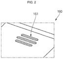
- FIG. 2 is an enlarged view of a region "A" of FIG. 1
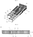
- FIG. 3 is an exploded perspective view of the energy storage module shown in FIGS. 1 and 2
- FIG. 4 is an exploded bottom perspective view of an extinguisher sheet and a top cover in the energy storage module shown in FIGS. 1 to 3 .
- an energy storage module 100 includes a cover member 110, a top plate 140, an extinguisher sheet 150, and a top cover 160.
- the cover member 110 provides an internal space for receiving (or accommodating) battery cells and insulation spacers.
- the cover member 110 includes a bottom plate 111, an end plate 112, and a side plate 113 which together form a space for arranging the battery cells and the insulation spacers.
- the cover member 110 may fix positions of the battery cells and the insulation spacers and may protect the battery cells from external impacts.
- the top plate 140 is coupled to a top portion (e.g., a top surface or a top) of the cover member 110.
- the top plate 140 may be coupled to the cover member 110 while covering top portions (e.g., top surfaces) of the battery cells.
- the positive electrode terminals and negative electrode terminals of the battery cells are exposed to (or through) the top plate 140, and bus bars 145 are coupled to the respective terminals, thereby connecting the battery cells to one another in series, in parallel, or in series/parallel.
- the top plate 140 includes a plurality of ducts 141 located to respectively correspond to vents, which are located on the top surface of each of the battery cells.
- the ducts 141 may be arranged in a direction, for example, in a length direction of the top plate 140. Accordingly, the gas discharged from the vent of one of the battery cells may move upwardly along a corresponding one of the ducts 141 of the top plate 140.
- the configuration and operation of the ducts 141 will be described in further detail below.
- the extinguisher sheet 150 is positioned between the top plate 140 and the top cover 160.
- the extinguisher sheet 150 may be provided as one or more members (or sheets) extending in a direction, for example, in a length direction of the top plate 140.
- the extinguisher sheet 150 may include openings (e.g., opening holes) 151 positioned to respectively correspond to the ducts 141 of the top plate 140. Accordingly, the extinguisher sheet 150 may be positioned such that the openings 151 therein are respectively aligned with the ducts 141 of the top plate 140.
- the extinguisher sheet 150 may be coupled to a bottom surface 160b of the top cover 160. Because the extinguisher sheet 150 is coupled to the bottom surface 160b of the top cover 160, the extinguisher sheet 150 may be positioned above the top plate 140. The configuration and operation of the extinguisher sheet 150 will be described below in further detail.
- the top cover 160 is coupled to the top portion of the top plate 140.
- the top cover 160 may cover the top plate 140 and the bus bar 145.
- the top cover 160 also covers the extinguisher sheet 150, which is coupled to the bottom surface 160b of the top cover 160, thereby protecting the top plate 140, the bus bar 145, and the extinguisher sheet 150 from external impacts applied to a top surface 160a of the top cover 160.
- the top cover 160 includes discharge openings (e.g., discharge holes) 161.
- the top cover 160 may include protrusion parts (e.g., protrusions) 162 spaced by a distance (e.g., a predetermined distance) apart from an outer periphery of (e.g., may extend around a periphery of) respective ones of the discharge holes 161, and the protrusion parts 162 downwardly protrude from the top cover 160.
- Openings (e.g., opening holes) 151 of the extinguisher sheet 150 may be coupled to (e.g., may extend around) an exterior of the respective ones of the protrusion part 162, and the ducts 141 may be coupled to (e.g., may extend into) the interior of the respective ones of the protrusion parts 162.
- the discharge holes 161 may each include a plurality of discharge holes (e.g., discharge sub-holes) arranged in a direction, for example, in a length direction, of the top cover 160.
- the discharge holes 161 are positioned to respectively correspond to the ducts 141 of the top plate 140.
- the discharge holes 161 may each be provided as a plurality of openings passing through the top and bottom surfaces of the top plate 140 and spaced apart from one another.
- the gases discharged from a vent 124a of a battery cell 120 when the vent 124a ruptures may be discharged to the exterior through the corresponding duct 141 of the top plate 140, and the corresponding discharge hole 161 of the top cover 160 and may facilitate user safety by preventing or substantially preventing a user's hand from contacting an internal structure of the top cover 160.
- a rack includes a plurality of shelves and a plurality of the energy storage modules 100 accommodated on the shelves.
- the rack may include a plurality of shelves mounted thereon to be spaced apart from one another, and one or more energy storage modules 100 may be accommodated in each of the plurality of shelves.
- a bottom surface of one of the energy storage modules 100 may contact a top surface of one of the shelves, and a bottom surface of another one of the energy storage modules 100 may be positioned on the top surface of another shelf while being spaced a distance apart from the top surface thereof.
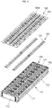
- FIG. 5 is a perspective view illustrating a secondary battery, a top plate, and a top cover in the energy storage module shown in FIGS. 1 to 4 .
- FIG. 6A illustrates a rack on which a plurality of energy storage modules are coupled according to an embodiment of the present disclosure
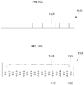
- FIG. 6B is a cross-sectional view taken along the line A-A of FIG. 5
- FIG. 6C is a cross-sectional view taken along the line B-B of FIG. 5
- FIG. 6D is an enlarged view of a region of FIG. 6B .
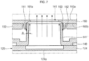
- FIG. 7 is a cross-sectional view of a duct according to an embodiment of the present disclosure.
- the ducts 141 located on the top plate 140 respectively correspond to vents 124a of the battery cells 120, and discharge holes 161 of the top cover 160 may be positioned to respectively correspond to the ducts 141 of the top plate 140.
- each of the battery cells 120 includes an electrode assembly accommodated in a case 121 and is shaped such that the cap plate 124 covers a top portion of the case 121.
- the electrode assembly may be configured by winding, stacking, or laminating a positive electrode plate and a negative electrode plate, each having a portion coated with an active material (e.g., a coating or coated portion), in a state in which a separator is positioned between the positive electrode plate and the negative electrode plate.
- a top portion of the case 121 may be sealed by a cap plate 124.
- the vent 124a is located at approximately a center of the cap plate 124 and has a smaller thickness than other regions of the cap plate 124.
- first and second electrode terminals 122 and 123 which are electrically connected to the electrode terminal may be positioned at opposite sides of the cap plate 124.
- the first electrode terminal 122 will be referred to as a negative electrode terminal
- the second electrode terminal 123 will be referred to as a positive electrode terminal, but the polarities thereof may be reversed. Occurrences of ignition of the battery cells 120 can be reduced by using particular compositions of active materials of the battery cells 120, thereby increasing safety.
- the energy storage module 100 may include a plurality of the energy storage modules 100 coupled to a rack 10.
- the number of energy storage modules 100 may be varied according to a desired capacity, and the energy storage modules 100 may be mounted in the rack 10 and then fixed thereto.
- the rack 10 may include a frame 11 defining an overall external shape of the rack 10, and shelves 12 at different levels of the frame 11 to support bottom portions (e.g., bottom surfaces) of the energy storage modules 100.
- two shelves 12 are shown in the frame 11 with energy storage modules 100 respectively mounted on the shelves 12, but the present disclosure is not limited to the numbers in the illustrated embodiment.
- the ducts 141 are passages through which the gas discharged through the vents 124a of the battery cells 120 passes, and protrude from the top plate 140.
- the duct 141 may have a cross-sectional shape, e.g., an elliptical shape, corresponding to the vent 124a of each of the battery cells 120.
- the duct 141 may taper away from a bottom portion thereof with the inner diameter thereof gradually decreasing upward.
- the duct 141 may have a uniform thickness and may be inclined at an angle (e.g. a predefined angle) ( ⁇ ) toward an interior thereof.
- the angle ( ⁇ ) of inclination of the duct 141 may be in a range from about 1° to about 5°, and, in an embodiment, from about 1° to about 3°.
- the duct 141 may have a height corresponding to that of the top cover 160.
- a height of the duct 141 may be in a range from 15 mm to 20 mm, and, in an embodiment, from 18 mm to 18.4 mm.
- the height of the duct 141 is greater than or equal to 15 mm, the gas generated from the vent 124a of the battery cell 120 can be prevented or substantially prevented from returning to the vent 124a even if the gas collides with the shelf 12 after moving along the duct 141.
- the height of the duct 141 is less than or equal to 20 mm, the duct 141 configured relative to the shelf 12 may be easily manufactured.
- the gas passing through the duct 141 may move toward the discharge hole 161 of the top cover 160.
- a duct 141' may taper away from a bottom portion thereof with the inner diameter thereof gradually decreasing upward.
- the duct 141' may be configured to have a thickness gradually decreasing from a bottom portion thereof to a top portion thereof.
- an interior surface of the duct 141' may be gradually upwardly inclined with an angle (e.g., a predefined angle) ( ⁇ ) to the exterior, and the exterior surface of the duct 141' may be gradually upwardly inclined with a an angle (e.g., a predefined angle) to the interior.
- an inclination angle of the interior of the duct 141' may be in a range from about 1° to about 5°, and, in an embodiment, from about 1° to about 3°.
- the inclination angle is greater than or equal to 1°, the gas generated from the vent 124a of the battery cell 120 can be easily accumulated upwardly.
- the inclination angle is less than or equal to 5°, rigidity of the duct 141' can be maintained and upward movement of the gas may be prevented or substantially prevented from being restricted by the duct 141'.
- the top cover 160 may include an exhaust area 161a having a plurality of discharge openings (e.g., discharge holes) 161 located therein, protrusion parts (e.g., protrusions) 162 located on a bottom surface of the top cover 160, and an inclined part 163 located between the exhaust area 161a and each of protrusion parts 162.
- the exhaust area 161a is positioned on a top portion of the duct 141 and can be defined by a region forming peripheries around the discharge holes 161.
- the exhaust area 161a may have a thickness D2 smaller than a thickness D1 of the top cover 160 (D1>D2).
- the thickness D2 of the exhaust area 161a may be two thirds (2/3) the thickness D1 of the top cover 160.
- the thickness D2 of the exhaust area 161a may be at least 1.0 mm. In this case, injection molding can be properly performed while minimizing or reducing occurrence of flames when the gas is discharged.
- the thickness D1 of the top cover 160 is about 2.5 mm
- the thickness D2 of the exhaust area 161a may be about 1.5 mm.
- the gas discharged through the vent 124a of the battery cell 120 can be exhausted through the discharge holes 161 located in the exhaust area 161a.
- the plurality of discharge holes 161 may have an overall area of greater than or equal to about 30% of the exhaust area 161a, thereby facilitating exhaust performance.
- a width W1 of each of the discharge holes 161 may be less than 3 mm.
- the width W1 of the discharge hole 161 is less than or equal to 3 mm, internal flames can be prevented or substantially prevented from spreading to the exterior and facilitating user safety by preventing or substantially preventing a user's hand from directly contacting the battery cell from the exterior of the top cover 160.
- the discharge holes 161 are positioned within the ducts 141, and top ends of the ducts 141 are covered by the exhaust area 161a. In some embodiments, regions of the exhaust area 161a, where the discharge holes 161 are not located, may extend into the interior of the ducts 141, as shown in FIG. 6C . In an embodiment, a distance D3 of the exhaust area 161a extending into the interior of each of the ducts 141 may be less than or equal to about 2 mm, and, in an embodiment, in a range from 1 mm to 1.5 mm.
- the protrusion parts 162 protrude from the bottom surface 160b of the top cover 160 and are coupled to the exterior of the ducts 141.
- the protrusion parts 162 may be shaped to respectively correspond to cross-sections of the ducts 141 and may cover (e.g. surround) the exhaust area 161a.
- a cross-sectional area of each of the protrusion parts 162 is greater than that of each of the ducts 141, such that a space may be created between each of the ducts 141 and each of the protrusion parts 162.
- a height D4 of each of the protrusion parts 162 may be in a range from about 2 mm to about 4 mm, and, in an embodiment, 3 mm. If the height of the protrusion part 162 is less than 2 mm, the protrusion part 162 may not be high enough to guide the gas colliding with the exhaust area 161a to the exterior of the duct 141. If the height of the protrusion part 162 is greater than 4 mm, the protrusion part 162 may be positioned excessively high, making it difficult to efficiently discharge the gas.
- a ratio of the height D4 of the protrusion parts 162 to the height of the duct 141 may be in a range from about 1:4 to about 1:9, and, in an embodiment, 1:6.
- the ratio of the height D4 of the protrusion parts 162 to the height of the duct 141 is greater than or equal to 1:4, the protrusion part 162 can be manufactured so as to easily cover the top portion of the duct 141.
- the ratio of the height D4 of the protrusion parts 162 to the height of the duct 141 is less than or equal to 1:9, the gas passing through the duct 141 can be easily guided upwardly.
- the inclined part 163 is positioned between the exhaust area 161a and the protrusion part 162. In an embodiment, since the exhaust area 161a having a relatively small thickness is connected to the protrusion part 162 in the top cover 160, the inclined part 163 is inclined. In some examples, the inclined part 163 may be configured to have a thickness gradually increasing toward the protrusion part 162 in the exhaust area 161a.
- the top end of the duct 141 is positioned at a bottom portion of the inclined part 163 ( i.e. the top end of the duct 141 is lower than the inclined part 163).
- the inclined part 163 may prevent or substantially prevent the gas discharged through the vent 124a of the battery cell 120 from penetrating back into the vent 124a.
- the inclined part 163 may have a slope in a range from about 30° to about 60°, and, in an embodiment, from about 40° to about 50°, with respect to the exterior surface of the duct 141.
- the slope of the inclined part 163 with respect to the exterior surface of the duct 141 is greater than or equal to 30°, the gas discharged through the vent 124a is allowed to be discharged to the exterior, thereby easily preventing or substantially preventing the gas from penetrating back into the vent 124a.
- the slope of the inclined part 163 with respect to the exterior surface of the duct 141 is less than or equal to 60°, the inclined part 163 can be integrated with the protrusion part 162.
- the vent 124a of the battery cell 120 ruptures, the gas moves upwardly along the duct 141, as indicated by the arrows.
- FIGS. 6B and 6C the vent 124a remaining in the cap plate 124 is shown.
- the vent 124a ruptures and may then be removed.
- the gas passing through the duct 141 may move toward the exterior through the discharge holes 161 of the top cover 160 positioned above the duct 141.
- a distance between the top surface 160a of the top cover 160 and the adjacent shelf 12 may be in a range from about 3 mm to about 7 mm.
- the distance is greater than or equal to about 3 mm, the heat generated from the energy storage module 100 can be easily discharged to the exterior.
- the distance is less than or equal to about 7 mm, a high-temperature inert gas atmosphere can be easily created, which will be further described below.
- a phase change may begin to occur in a fire extinguishing agent in the extinguisher sheet 150 at a temperature in a range from about 40°C to 60°C, and more specifically, a temperature in a range from 45°C to 55°C.
- the fire extinguishing agent may remain inside the extinguisher sheet 150 instead of being sprayed (released) therefrom.
- a gas containing an electrolytic steam may be generated mainly through the vent.
- the gas in the above temperature range may allow a heat-resistant plastic constituting an upper plate 140 and an upper cover 160 to remain unmelted.
- spraying of some of the fire extinguishing agent may begin.
- the inclined part 163 of the top cover 160 may prevent or substantially prevent the initially generated combustible gas having a relatively low temperature from being induced into the vent.
- high-temperature inert gas may be generated with flames.
- the inert gas may fill a space between the top surface 160a of the top cover 160 and the adjacent shelf 12 to create an inert gas atmosphere.
- the inert gas may also fill the internal space of the duct 141, thereby preventing or substantially preventing oxygen induction, and preventing or substantially preventing flames generated in the battery cell 120 from being propagated to neighboring battery cells 120 or another energy storage module.
- the extinguisher sheet 150 which is positioned under the top cover 160, may operate in response to the high-temperature inert gas to emit or spray the fire extinguishing agent, which will be described in further detail below.
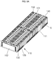
- FIG. 8A is a perspective view of the extinguisher sheet coupled to the top plate of the energy storage module shown in FIGS. 1 to 3 ; and FIG. 8B is an enlarged view of a region "B" of FIG. 8A .
- FIGS. 9A and 9B are cross-sectional views illustrating a state in which an extinguisher sheet operates in the energy storage module shown in FIGS. 1 to 3 .
- FIGS. 10A to 10D are cross-sectional views illustrating some example configurations of extinguisher sheets in the energy storage module according to embodiments of the present disclosure.
- the extinguisher sheet 150 is positioned between the top plate 140 and the top cover 160, as described above. As shown in FIG. 8A , the extinguisher sheet 150 may have opening holes 151 coupled to the ducts 141 of the top plate 140. Accordingly, movement of the gases through the ducts 141 may not be influenced by the extinguisher sheet 150.
- the extinguisher sheet 150 may operate (e.g., may emit the fire extinguishing agent) in response to heat when the inert gas having a relatively high temperature of, for example, about 200 oC, is generated.
- the fire extinguishing agent contained in the extinguisher sheet 150 is emitted by (e.g., is sprayed from) the extinguisher sheet 150 in response to the high-temperature gas.
- the fire extinguishing agent may be directionally emitted (or sprayed) toward a direction away from the bottom surface 160b of the top cover 160.
- the fire extinguishing agent may reach the underlying insulation spacers through openings (e.g., fire extinguishing agent openings or opening holes) 143 located between adjacent ones of the ducts 141 of the top plate 140.
- a fluid guide protrusion 142 may further be provided around the openings 143, thereby efficiently guiding the movement of the fire extinguishing agent toward the insulation spacers.
- the fire extinguishing agent may move along surfaces of the insulation spacers, thereby extinguishing a fire on a battery cell 120 and cooling the battery cell 120.
- the extinguisher sheet 150 may include any of various example types of extinguisher sheets, as shown in FIGS. 10A to 10D .
- the extinguisher sheet 150 may include receiving parts 152 for receiving (e.g., accommodating or storing) a fire extinguishing agent within an external case made of polyurea and polyurethane.
- the receiving parts 152 of the extinguisher sheet 150 may be in forms of micro-sized capsules capable of encapsulating the internal fire extinguishing agent, which includes a halogenated carbon compound (e.g.
- a halogen containing hydrocarbon compound such as a compound consisting only of carbon and halogen atoms
- a halogenated ketone based fire extinguishing agent NOVEC
- the fire extinguishing capsules forming the receiving parts 152 of the extinguisher sheet 150 open (or rupture) to emit the internal fire extinguishing agent when the gas passing through the duct 141 of the top plate 140 reaches a relatively high temperature of about 200 oC.
- phase transformation of the fire extinguishing agent may start at a temperature of about 50 oC or at a temperature in a range from about 100 oC to about 200 oC, and the fire extinguishing capsules may open due to the pressure applied during the phase transformation in a high temperature atmosphere of about 200 oC, such that the internal fire extinguishing agent encapsulated within the fire extinguishing capsules is emitted.
- a ratio of the weight of the fire extinguishing agent in the extinguisher sheet 150 to a total weight of the extinguisher sheet 150 may be in a range from 30% to 50%.
- a proportion of the fire extinguishing agent contained in the extinguisher sheet 150 to the overall weight of the extinguisher sheet 150 may be in a range from about 30% to about 50%.
- the extinguisher sheet 150 may be easily set to operate (e.g., rupture) at about 200 oC.
- an amount of the fire extinguishing agent may be in a range from 0.12 g/cm 3 to 0.82 g/cm 3 .
- the fire extinguishing agent contained in the extinguisher sheet 150 is appropriate for the capacity of battery cells used in the energy storage module 100 including the extinguisher sheet 150 so as to be able to extinguish a fire on any one of the battery cells.
- the extinguisher sheet 150 may be easily set to operate (e.g., rupture) at about 200 oC or higher.
- another example extinguisher sheet 150A may include a tube-type receiving space 152A for receiving (e.g., accommodating or storing) a fire extinguishing agent within the receiving space 152A.
- another example extinguisher sheet 150B may include receiving spaces 152B arranged within the extinguisher sheet 150B to be spaced apart from each other by a distance (e.g., a regular distance).
- the receiving spaces 152B may include a plurality of receiving spaces to be spaced apart from one another, unlike in the tube-type extinguisher sheet 150A shown in FIG. 10B .
- the receiving spaces 152B of the extinguisher sheet 150B may open (e.g., rupture) responsive to only one of the battery cells 120, from which a relatively high-temperature gas is generated, to then emit the fire extinguishing agent. Therefore, when the gas is generated from the plurality of battery cells 120, a fire on a corresponding one of the battery cells 120 can be extinguished.
- another example extinguisher sheet 150C may have a multi-layered structure including different types of layers.
- the extinguisher sheet 150C may include an underlying first extinguisher sheet 150 having capsules 152 located therein, and an overlying second extinguisher sheet 150A having a tube-type receiving space 152A.
- the first extinguisher sheet 150 and the second extinguisher sheet 150A may be set to operate at different temperatures.
- the first extinguisher sheet 150 and the second extinguisher sheet 150A may operate in sequence according to the temperature and amount of the discharged gas.
- the extinguisher sheet 150C may operate in sequence according to the temperature and the time of gas generated, thereby constantly emitting the fire extinguishing agent.
- FIG. 11 is a perspective view of battery cells and insulation spacers arranged in a bottom plate of the energy storage module shown in FIGS. 1 to 3 ;
- FIG. 12 is a cross-sectional view taken along the line C-C of FIG. 1 ;
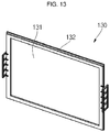
- FIG. 13 is a perspective view illustrating a configuration of an insulation spacer in the energy storage module shown in FIGS. 1 to 3 ;
- FIGS. 14A and 14B are exploded perspective views illustrating some example configurations of sheet parts of the insulation spacers in the energy storage module according to embodiments of the present disclosure;
- FIG. 15 is a cross-sectional view taken along the line D-D of FIG. 14A after the sheet parts are adhered to each other; and
- FIG. 16 is an enlarged view of a region "C" of FIG. 12 .
- the battery cells 120 may be alternately arranged on a top surface of the bottom plate 111 of the cover member 110 with the insulation spacers 130 (e.g., with the insulation spacers 130 arranged between adjacent ones of the battery cells 120).
- the battery cells 120 may be arranged in a plurality of columns (e.g., two columns) along the top surface of the bottom plate 111, and the insulation spacers 130 may be positioned between adjacent ones of the battery cells 120.
- Each of the battery cells 120 includes an electrode assembly accommodated in a case 121.
- the electrode assembly may be configured by winding, stacking, or laminating a positive electrode plate and a negative electrode plate, each having a portion coated with an active material (e.g., a coating or coated portion), in a state in which a separator is positioned between the positive electrode plate and the negative electrode plate.
- electrode terminals 122 and 123 which are electrically connected to uncoated regions (e.g., uncoated portions) of the positive and negative electrode plates, may be exposed at an upper portion of the case 121 through the cap plate 124.
- the electrode terminals 122 and 123 may be referred to as a first electrode terminal 122 and a second electrode terminal 123, respectively, defining, for example, a negative electrode terminal and a positive electrode terminal, but the polarities thereof may be reversed. Occurrences of ignition of the battery cells 120 can be reduced by using particular compositions of active materials of the battery cells 120, thereby increasing safety.
- the battery cells 120 and insulation spacers 130 may be alternately arranged on a top surface of the bottom plate 111 of the cover member 110.
- the battery cells 120 may be arranged such that the long side surface of one of the battery cells 120 is spaced a distance (e.g., a reference or predetermined distance) apart from a long side surface of another (e.g., an adjacent) one of the battery cells 120, and the insulation spacers 130 are positioned between the neighboring battery cells 120.
- the distance (e.g., a first distance) between the long side surfaces of the two neighboring battery cells 120 may be in a range from about 4 mm to about 6 mm.
- the first distance is smaller than 4 mm, it is not easy to provide air layers between the battery cells 120 and the insulation spacers 130, thereby lowering cooling efficiency. If the first distance is greater than 6 mm, the energy storage module 100 may become unnecessarily bulky.
- each of the insulation spacers 130 positioned between each of the battery cells 120 may prevent or substantially prevent the battery cells 120 from contacting each other, thereby maintaining the cases 121 of the battery cells 120 in an electrically isolated state.
- each of the insulation spacers 130 may have a planar size corresponding to that of the long side surface of one battery cell 120.
- one surface of the insulation spacer 130 may face the long side surface of one battery cell 120, and the other surface of the insulation spacer 130 may face the long side surface of another battery cell 120.
- the insulation spacer 130 and the long side surface of the battery cell 120 may be spaced apart by a distance (e.g., a second distance) to define a passage for external air.
- the battery cell 120 may be cooled by the external air passing through the external air passage.
- the insulation spacers 130 may include a sheet part (e.g., a sheet) 131 and an edge part (e.g., an edge) 132.
- the sheet part 131 may include a flame-retardant (or non-combustible) sheet that prevents (or substantially impedes) a fire from spreading to neighboring battery cells 120 and a heat-insulating sheet that prevents (or substantially impedes) heat from being propagated to neighboring battery cells 120 when a fire starts in any of the battery cells 120.
- the sheet part 131 may include a heat-insulating first sheet 131a and a plurality of (e.g., two) flame-retardant (or non-combustible) second sheets 131b adhered to opposite surfaces of the first sheet 131a by one or more adhesion members 131c.
- the sheet part 131 may have an increased heat insulating effect and may provide flame retardancy (and non-combustibility) by stacking multiple layers of the first sheet 131a and the second sheets 131b.
- the insulation spacers 130 may prevent or substantially prevent heat or flames from propagating to neighboring battery cells 120 through the stacked sheet parts 131 when the temperature of the battery cell 120 rises or flames are generated in the battery cell 120.
- the insulation spacers 130 may include a flame-retardant (or non-combustible) sheet that prevents (or substantially impedes) flames from propagating to neighboring battery cells 120 and a heat-insulating sheet that prevents (or substantially impedes) heat from being propagated to neighboring battery cells 120 when a fire starts in any of the battery cells 120, and configurations of the insulation spacers 130 will be described later in further detail.
- the first sheet 131a and the second sheets 131b may have a same size (e.g., the same length and width).
- a thickness of the insulation spacer 130 may not exceed 50% of the first distance (e.g., may not exceed 50% of the distance between the adjacent battery cells 120).
- the first distance is about 6 mm
- the thickness of the insulation spacer 130 may not exceed about 3 mm.
- the thickness of the insulation spacer 130 may not exceed about 2 mm.
- the first sheet 131a may have a thickness in a range from about 1 mm to about 1.4 mm.
- each of the second sheets 131b may have a thickness in a range from about 0.1 mm to about 0.2 mm
- the adhesive member 131c may have a thickness of about 0.1 mm.
- the first sheet 131a may include (or may be formed of) ceramic paper, and the second sheets 131b may include (or may be formed of) mica (e.g. mica paper).
- the first sheet 131a may further include an aerogel.
- the first sheet 131a may include (or may be) ceramic paper made of a fiber-containing refractory insulating material.
- the first sheet 131a may include (or may be) bio-soluble fiber ceramic paper (e.g . ceramic fiber) containing an alkali earth metal, which is an eco-friendly high-temperature insulating material that is generally harmless to humans.
- the sheet part 131 may have a configuration shown in FIG. 14A or FIG. 14B .
- the adhesion member 131c is positioned between the opposite ends x1 of the first sheet 131a and each of the second sheets 131b such that the sheet part 131 has a reference (or predetermined) width.
- the adhesion member 131c may attach the first sheet 131a and the second sheets 131b to each other.
- the adhesion member 131c may have a same length as the first sheet 131a and the second sheets 131b in a length direction.
- opposite ends x1 of the first sheet 131a may be adhered to respective opposite ends x1 of the second sheets 131b by the adhesion member 131c.
- the adhesion member 131c may have a width in a range from about 10 mm to about 20 mm.
- the width of the adhesion member 131c is smaller than about 10 mm, adhesion between the first sheet 131a and the second sheets 131b may be insufficient. If the width of the adhesion member 131c is greater than about 20 mm, an ignition probability may increase due to the adhesion member 131c.
- the adhesion member 131c may have any of a variety of adhesive components or configurations, such as a double-sided tape or an adhesive tape, but the adhesive components and configurations of the adhesion member 131c are not limited thereto.
- the adhesion member 131c may attach (e.g., may only attach) the opposite ends x1 of the first sheet 131a to the second sheets 131b such that the first sheet 131a and the second sheets 131b are spaced apart from each other at a central portion x2 of the sheet part 131.
- air passages 131d may be established between the first sheet 131a and the second sheets 131b.
- the air passages 131d established at the central portion x2 of the sheet part 131 may reduce (or mitigate) compression of the sheet part 131.
- the adhesion member 131c may be located at an area at (or adjacent to) top and bottom ends of the first sheet 131a to attach the first sheet 131a and the second sheets 131b to each other.
- the adhesion member 131c may have a same width as the first sheet 131a and the second sheets 131b in a width direction.
- the top and bottom ends of the first sheet 131a may be respectively adhered to top and bottom ends of the second sheets 131b by the adhesion member 131c.
- the adhesion member 131c may be attached to the opposite ends of the sheet part 131.
- an adhesion area e.g., a vertical adhesion area
- an adhesion area may be reduced relative to the overall area of the sheet part 131 due to an area occupied by the adhesion member 131c attached to the opposite ends of the sheet part 131, thereby lowering adhesion performance.
- the adhesion member 131c may be applied to the top and bottom ends thereof to increase the adhesion area, thereby improving the adhesion performance.
- the configuration of the sheet part 131 shown in FIG. 14B may be substantially the same as the sheet part 131 shown in FIGS. 14A and 15 , except for positions of the adhesion members 131c.
- the adhesion performance when the adhesion member 131c is applied to the top and bottom ends of the sheet part 131, the adhesion performance may be improved, and in some embodiments, no edge part (described below) may be separately required (e.g., an edge part may be omitted).
- the edge part 132 may be provided along peripheral edges of the sheet part 131.
- the edge part 132 may include (or may be made of) a plastic material, such as a general polyethylene or polypropylene, and may be coupled to edges of the sheet part 131 by using a double injection process to fix the shape of the sheet part 131.
- the edge part 132 may have a width in a range from about 3 mm to about 6 mm. If the width of the edge part 132 is smaller than about 3 mm, the sheet part 131 may not be easily fixed, and if the width of the edge part 132 is greater than about 6 mm, an ignition probability of the edge part 132 made of a plastic material may be increased.
- the fire extinguishing agent when a fire extinguishing agent is applied from top portions of the insulation spacers 130, the fire extinguishing agent may move downwardly along the surfaces of the sheet part 131. Therefore, the fire extinguishing agent may contact the case 121 of the adjacent battery cells 120, thereby performing extinguishing and cooling operations on the battery cells 120.
- movement of the fire extinguishing agent will be described in further detail.
- the top plate 140 may further include the openings 143 respectively located to correspond to (e.g., located over or above) the insulation spacers 130. Accordingly, the fire extinguishing agent, when emitted from the extinguisher sheet 150, may pass through the top plate 140 through the openings 143 of the top plate 140 to reach the insulation spacers 130. In addition, the fire extinguishing agent may move along surfaces of the insulation spacers 130 that face the case 121 of the adjacent battery cells 120, thereby extinguishing a fire and cooling the battery cells 120.
- the fire extinguishing agent is emitted by the extinguisher sheet 150 located over one or more of the battery cells 120, the temperature of which is higher than a reference temperature (e.g. 200 oC). Therefore, the fire extinguishing agent may be sprayed from a top portion of the battery cell 120 having an elevated temperature.
- a reference temperature e.g. 200 oC.
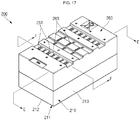
- FIG. 17 is a perspective view of an energy storage module according to another embodiment of the present disclosure
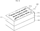
- FIG. 18 is a bottom perspective view of the energy storage module shown in FIG. 17
- FIG. 19 is a perspective view illustrating a state in which battery cells and insulation spacers are arranged in a cover member of the energy storage module according to an embodiment of the present disclosure
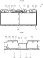
- FIG. 20 is a cross-sectional view taken along the line E-E of FIG. 17
- FIG. 21 is an enlarged view of a region "D" of FIG. 20 .
- the energy storage module 200 includes a cover member 210, battery cells 120, insulation spacers 230, a top plate 240, an extinguisher sheet 250, and a top cover 260.
- the energy storage module 200 may be smaller in size than the energy storage module 100 described above, such that a smaller number of battery cells 120 can be received in a space of the energy storage module 200, which is formed together by the cover member 210, the top plate 240, and the top cover 260, than in the energy storage module 100. Therefore, configurations and sizes of the cover member 210, the top plate 240, and the top cover 260 may vary according to the number of battery cells received therein.
- the energy storage module 200 may be basically configured in a similar manner as the energy storage module 100.
- the cover member 210 may include a bottom plate, an end plate (or a plurality of end plates), and a side plate (or a plurality of side plates) which together form a space in which the battery cells 120 and the insulation spacers 230 are alternately arranged with the battery cells 120 on the bottom plate.
- the cover member 210 may fix positions of the battery cells 120 and the insulation spacers 230 and may protect the battery cells 120 from external impacts.
- the bottom plate may further include through-holes 211a, through which the fire extinguishing agent from the extinguisher sheet 250 and the air moving along the exterior surfaces of the insulation spacers 230 are exhausted.
- the through-holes 211a may be positioned to correspond to the insulation spacers 230.
- the insulation spacers 230 are positioned between adjacent ones of the battery cells 120 to prevent or substantially prevent the battery cells 120 from contacting one another, thereby maintaining the cases 121 of the battery cells 120 in electrically isolated states.
- each of the insulation spacers 230 may have short side surfaces, each having a planar size sufficient to entirely cover the long side surfaces of two adjacent battery cells 120.
- one of the insulation spacers 230 may be positioned between each group of four adjacent battery cells 120, which are arranged such that long side surfaces of two of the four battery cells 120 face each other.
- the insulation spacers 230 may include (or may be made of) a flame-retardant (or non-combustible) sheet that prevents (or substantially mitigates) a fire from spreading to neighboring battery cells and a heat-insulating sheet that prevents (or substantially mitigates) heat from propagating to neighboring battery cells when a fire outbreaks in any of the battery cells 120.
- a flame-retardant (or non-combustible) sheet that prevents (or substantially mitigates) a fire from spreading to neighboring battery cells
- a heat-insulating sheet that prevents (or substantially mitigates) heat from propagating to neighboring battery cells when a fire outbreaks in any of the battery cells 120.
- the top plate 240 is coupled to a top portion of the cover member 210.
- the top plate 240 may be coupled to the cover member 210 while covering top portions of the battery cells 120.
- the top plate 240 includes ducts 241 respectively corresponding to the vents 124a located on a top surface of each of the battery cells 120.
- the ducts 241 may be arranged in a direction, for example, in a length direction of the top plate 240. Accordingly, if the vent 124a ruptures, the gas discharged through the vent 124a of the battery cell 120 may move upwardly along the duct 241 of the top plate 240.
- the configurations and operations of the ducts 241 will be described in further detail below.
- the extinguisher sheet 250 is positioned between the top plate 240 and the top cover 260.
- the extinguisher sheet 250 may include a plurality of planar sheets located at opposite sides of the ducts 241 of the top plate 240 and extending in a length direction of the top plate 240.
- the extinguisher sheet 250 may be mounted on a bottom surface 260b of the top cover 260.
- the length direction may refer to a direction in which the ducts 241 of the top plate 240 extend.
- the top cover 260 is coupled to the top portion of the top plate 240.
- the top cover 260 may cover the top plate 240 and the extinguisher sheet 250, thereby protecting the top plate 240 and the extinguisher sheet 250 from external impacts applied to a top surface 260a of the top cover 260.
- the top cover 260 may include an exhaust area 265 having discharge holes 261 located therein, and protrusion parts (e.g., protrusions) 262 located on the bottom surface 260b of the top cover 260.
- the ducts 241 may be respectively coupled to (e.g., may respectively extend into) the interior of the protrusion parts 262.
- each of the discharge holes 261 may include a plurality of discharge holes arranged in a direction, for example, in a length direction of the top cover 260.
- the discharge holes 261 may be positioned to correspond to the ducts 241 of the top plate 240. Accordingly, if the vent 124a of the battery cell 120 ruptures, the gas discharged through the vent 124a of the battery cell 120 may move to the exterior along the ducts 241 of the top plate 240 and the discharge holes 261 of the top cover 260.
- the exhaust area 265 having the discharge holes 261 has a smaller height than other regions in the top cover 260.
- the exhaust area 265 is configured to downwardly protrude from the top cover 260 to establish a gas movement passage therein.
- the exhaust area 265 is coupled to the top portion of the duct 241.
- the protrusion part 262 located on the bottom surface of the exhaust area 265 is coupled to the exterior of the duct 241.
- the duct 241 may be configured to have a smaller height than the top cover 260.
- the gas discharged through the ducts 241 and the discharge holes 261 may gather in the gas movement passage located on the exhaust area 265.
- the gas may be discharged to an exterior side by using, for example, a separate fan or a suction structure (e.g., a vacuum), thereby allowing the gas generated by the battery cells 120 to be discharged quickly.
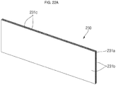
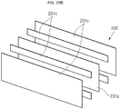
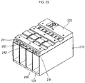
- FIGS. 22A and 22B are a perspective view and an exploded perspective view, respectively, illustrating configurations of insulation spacers in the energy storage module shown in FIGS. 17 to 21 ; and FIG. 23 is a cross-sectional view taken along the line F-F of FIG. 17 .
- the battery cells 120 and the insulation spacers 230 may be alternately arranged on a top surface of the bottom plate of the cover member 210.
- each of the insulation spacers 230 may have side surfaces, each having a planar size sufficient to entirely cover long side surfaces of two adjacent battery cells 120.
- one surface of one of the insulation spacers 230 may entirely cover the long side surfaces of two adjacent battery cells 120, and the other surface of the one insulation spacer 230 may entirely cover the long side surfaces of two other adjacent battery cells 120.
- one of the insulation spacers 230 may be positioned between four battery cells 120 that are arranged such that long side surfaces of two battery cells 120 face long side surfaces of two other battery cells 120.
- long side surfaces of the battery cells 120 may be spaced by a distance (e.g., a predetermined distance) apart from long side surfaces of facing battery cells 120, and the insulation spacers 230 may be positioned between each of the long side surfaces of the battery cells 120.
- a distance (e.g., a first distance) between the long side surfaces of the facing battery cells 120 may be in a range from about 3.5 mm to about 4.5 mm. If the first distance is smaller than about 3.5 mm, air layers (e.g., air passages) may not be provided between each of the battery cells 120 and the insulation spacers 230, thereby lowering cooling efficiency. If the first distance is greater than about 4.5 mm, the energy storage module 200 may become unnecessarily bulky.
- the insulation spacers 230 may prevent or substantially prevent the battery cells 120 from contacting each other, thereby maintaining the cases 121 of the battery cells 120 in electrically isolated states.
- the insulation spacer 230 and the long side surfaces of battery cells 120 are spaced apart from each other to establish external air passages.
- the battery cells 120 may be cooled by external air moving along (or through) the external air passages.
- the insulation spacers 230 may consist of sheet parts without separate edge parts.
- the insulation spacers 230 may include a flame-retardant (or non-combustible) sheet that prevents (or substantially mitigates) the fire from spreading to neighboring battery cells 120 and a heat-insulating sheet that prevents (or substantially mitigates) heat from propagating to neighboring battery cells 120.
- the sheet parts of the insulation spacers 230 may include a heat-insulating first sheet 231a and two flame-retardant (or non-combustible) second sheets 231b respectively adhered to opposite surfaces of the first sheet 231a by using one or more adhesive members 231c.
- first sheet 231a and the second sheets 231b have a same (or substantially the same) size.
- a thickness of the insulation spacer 230 may not exceed about 50% of the first distance to facilitate movement of the fire extinguishing agent, which will be described in further detail below.
- the adhesion member 231c may be positioned between the first sheet 231a and the second sheets 231b at a distance (e.g., a predetermined distance) from top and bottom ends of the first sheet 231a to attach the first sheet 231a and the second sheets 231b to each other.
- the adhesion member 231c may have a same (or substantially the same) width as the first sheet 231a and the second sheets 231b in their width directions.
- the top and bottom ends of the first sheet 231a may be respectively adhered to top and bottom ends of the second sheet 231b by the adhesion member 231c.
- the first sheet may be adhered at the top and bottom ends thereof by the adhesion member 231c, thereby improving the adhesion performance.
- the adhesion performance may be lowered when the first sheet 231a and the second sheets 231b are adhered to each other at the opposite ends of the sheet part by the adhesion member 231c, like in the embodiment shown in FIG. 14A .
- the sheet part 231 may have a same or similar configuration as that of the sheet part 131 shown in FIG. 14B .
- the fire extinguishing agent may move downwardly along the surfaces of the sheet part 231. Therefore, the fire extinguishing agent may contact the case 121 of the adjacent battery cells 120, thereby extinguishing a fire and cooling the battery cells 120.
- the movement of the fire extinguishing agent and the cooling of the battery cells 120 using the air will be described in further detail.
- the top plate 240 may further include openings (e.g., opening holes) 243 located to respectively correspond to the insulation spacers 230. Accordingly, the fire extinguishing agent emitted from the extinguisher sheet 250 may pass through the top plate 240 through the openings 243 of the top plate 240 to reach the insulation spacers 230. In addition, the fire extinguishing agent may move along surfaces of the insulation spacers 230 that face the case 121 of the battery cells 120, thereby extinguishing and cooling the battery cells 120.
- openings e.g., opening holes
- the fire extinguishing agent is emitted (or sprayed) from the extinguisher sheet 250 above one or more of the battery cells 120, the temperature of which is higher than a reference temperature. Therefore, the fire extinguishing agent may be sprayed from a top portion of the battery cell 120, the temperature of which has increased. In addition, because the fire extinguishing agent moves along the surfaces of the insulation spacers 230 positioned at front and rear sides of the corresponding battery cell 120, the corresponding battery cell 120 can be both extinguished and cooled.
- top cover 260 may further include through-holes 263 that pass through top and bottom surfaces of the top cover 260 and are located to respectively correspond to the openings 243.
- the through-holes 263 may respectively correspond to the insulation spacers 230.
- the bottom plate 211 of the cover member 210 may also include through-holes 211a located to respectively correspond to the insulation spacers 230.
- air introduced through the through-holes 263 of the top cover 260 and the openings 243 of the top plate 240 may move along spaces provided between the insulation spacers 230 and the battery cells 120 to be discharged through the openings 211a of the bottom plate 211.
- the movement of the air e.g., the airflow direction
- air passages may be provided by the through-holes 211a and 263 and the openings 243, thereby improving cooling efficiency.
- FIGS. 24A and 24B are a perspective view and a cross-sectional view, respectively, of a battery cell used in an energy storage module according to an embodiment of the present disclosure.
- the battery cell 120 is configured such that an electrode assembly 125 is accommodated in a case 121, and a cap plate 124 covers a top portion of the case 121.
- a vent 124a having a smaller thickness than other regions is located approximately at a center of the cap plate 124.
- a duct 141 of the top plate 140 is located to correspond to a top portion of a vent 124a, as described above.
- the electrode assembly 125 may be electrically connected to a first electrode terminal 122 and a second electrode terminal 123 located on the cap plate 124 through a pair of current collectors 126.
- the first electrode terminal 122 will be referred to as a negative electrode terminal
- the second electrode terminal 123 will be referred to as a positive electrode terminal, but polarities thereof may be reversed.
- the electrode assembly 125 may include a negative electrode 125a, a positive electrode 125b positioned to face the negative electrode 125a, and a separator 125c positioned between the negative electrode 125a and the positive electrode 125b, and the electrode assembly 125 may be accommodated in the case 121 together with an electrolyte (not shown).
Landscapes
- Chemical & Material Sciences (AREA)
- Chemical Kinetics & Catalysis (AREA)
- General Chemical & Material Sciences (AREA)
- Electrochemistry (AREA)
- Engineering & Computer Science (AREA)
- Manufacturing & Machinery (AREA)
- Business, Economics & Management (AREA)
- Emergency Management (AREA)
- Health & Medical Sciences (AREA)
- Public Health (AREA)
- Battery Mounting, Suspending (AREA)
Applications Claiming Priority (1)
| Application Number | Priority Date | Filing Date | Title |
|---|---|---|---|
| KR1020190110367 | 2019-09-05 |
Publications (2)
| Publication Number | Publication Date |
|---|---|
| EP3790101A1 true EP3790101A1 (de) | 2021-03-10 |
| EP3790101B1 EP3790101B1 (de) | 2025-07-16 |
Family
ID=72380988
Family Applications (1)
| Application Number | Title | Priority Date | Filing Date |
|---|---|---|---|
| EP20194592.0A Active EP3790101B1 (de) | 2019-09-05 | 2020-09-04 | Energiespeichermodul |
Country Status (6)
| Country | Link |
|---|---|
| US (1) | US11735795B2 (de) |
| EP (1) | EP3790101B1 (de) |
| KR (1) | KR20210029132A (de) |
| CN (2) | CN112448079B (de) |
| HU (1) | HUE072646T2 (de) |
| PL (1) | PL3790101T3 (de) |
Cited By (6)
| Publication number | Priority date | Publication date | Assignee | Title |
|---|---|---|---|---|
| EP3836270A1 (de) * | 2019-12-11 | 2021-06-16 | Samsung SDI Co., Ltd. | Batteriesatz |
| EP3907817A1 (de) * | 2020-05-07 | 2021-11-10 | SK Innovation Co., Ltd. | Batteriezellentragekasten |
| EP3982463A1 (de) * | 2020-10-12 | 2022-04-13 | Samsung SDI Co., Ltd. | Batteriepack |
| EP4435962A4 (de) * | 2023-01-19 | 2024-12-04 | Contemporary Amperex Technology (Hong Kong) Limited | Batteriezelle, batterie und elektrische vorrichtung |
| EP4379910A4 (de) * | 2021-12-24 | 2025-06-11 | LG Energy Solution, Ltd. | Batteriepack mit verbesserter sicherheit |
| DE102022127324B4 (de) * | 2022-10-18 | 2025-10-23 | Dr. Ing. H.C. F. Porsche Aktiengesellschaft | Batterieeinrichtung für ein wenigstens teilweise elektrisch angetriebenes Kraftfahrzeug |
Families Citing this family (7)
| Publication number | Priority date | Publication date | Assignee | Title |
|---|---|---|---|---|
| US20230395934A1 (en) * | 2019-09-05 | 2023-12-07 | Samsung Sdi Co., Ltd. | Energy storage module having an extinguisher sheet |
| CN113285136B (zh) * | 2021-03-08 | 2022-12-27 | 深圳供电局有限公司 | 一种用于远程通信蓄电池组的安全保护装置 |
| CN114497873B (zh) * | 2022-01-30 | 2023-09-08 | 孚能科技(赣州)股份有限公司 | 一种隔热复合组件及其制备方法、电池模组和电池包 |
| JP7827473B2 (ja) * | 2022-02-03 | 2026-03-10 | 株式会社Subaru | バッテリカバー |
| KR102927405B1 (ko) * | 2022-11-21 | 2026-02-12 | 주식회사 엘지에너지솔루션 | 안전성이 강화된 배터리 팩 |
| KR20240084197A (ko) * | 2022-12-06 | 2024-06-13 | 주식회사 엘지에너지솔루션 | 커버 일체형 벤팅덕트를 구비하는 배터리 팩 |
| US20240204342A1 (en) * | 2022-12-15 | 2024-06-20 | Polestar Performance Ab | Methods and systems for burst valve battery cell ventilation |
Citations (4)
| Publication number | Priority date | Publication date | Assignee | Title |
|---|---|---|---|---|
| WO2013006796A1 (en) * | 2011-07-07 | 2013-01-10 | Federal Express Corporation | Battery cooling method and system |
| CN207199806U (zh) * | 2017-08-29 | 2018-04-06 | 合肥国轩高科动力能源有限公司 | 一种减缓电池热失控传播的隔热片 |
| CN207977389U (zh) * | 2018-01-29 | 2018-10-16 | 浙江美都海创锂电科技有限公司 | 一种安全防爆方形电池模块 |
| WO2019117485A1 (ko) * | 2017-12-11 | 2019-06-20 | 삼성에스디아이 주식회사 | 배터리 팩 |
Family Cites Families (84)
| Publication number | Priority date | Publication date | Assignee | Title |
|---|---|---|---|---|
| DE3842966A1 (de) | 1988-12-21 | 1990-06-28 | Bayer Ag | Transparente laminate |
| ATE310321T1 (de) | 1995-06-28 | 2005-12-15 | Ube Industries | Nichtwässrige sekundärbatterie |
| GB9516850D0 (en) * | 1995-08-17 | 1995-10-18 | Programme 3 Patent Holdings | High temperature storage battery |
| US6136423A (en) | 1996-01-11 | 2000-10-24 | Fitzpatrick; Peter J. | Fire fighting apparatus |
| US6719150B2 (en) | 2001-05-30 | 2004-04-13 | Kim Manufacturing Company | Battery rack and system |
| US7078129B2 (en) | 2002-01-11 | 2006-07-18 | Advanced Battery Technology Ltd. | Fire and corrosion resistant thermally stable electrodes and batteries and method for manufacturing same |
| IES20040437A2 (en) | 2003-06-26 | 2005-02-09 | Peter J Fitzpatrick | A fire fighting apparatus |
| KR100853618B1 (ko) | 2006-01-04 | 2008-08-25 | 주식회사 엘지화학 | 안전장치를 구비하고 있는 중대형 전지팩 |
| US20110313084A1 (en) | 2006-07-27 | 2011-12-22 | Ppg Industries Ohio, Inc. | Coating compositions comprising polyurea and graphite |
| KR101067627B1 (ko) | 2006-11-13 | 2011-09-26 | 주식회사 엘지화학 | 콤팩트한 구조와 우수한 방열 특성의 전지모듈 |
| JP5181743B2 (ja) | 2008-03-11 | 2013-04-10 | パナソニック株式会社 | 電力供給機器とそれを用いた電子機器 |
| WO2010026731A1 (ja) | 2008-09-05 | 2010-03-11 | パナソニック株式会社 | 電池パック |
| JP5405102B2 (ja) | 2008-12-27 | 2014-02-05 | 三洋電機株式会社 | バッテリシステム |
| WO2010098067A1 (ja) | 2009-02-24 | 2010-09-02 | パナソニック株式会社 | 電池モジュールとそれを用いた電池モジュール集合体 |
| US8557437B2 (en) | 2009-03-25 | 2013-10-15 | Tdk Corporation | Electrode comprising protective layer for lithium ion secondary battery and lithium ion secondary battery |
| KR101191660B1 (ko) | 2010-11-08 | 2012-10-17 | 에스비리모티브 주식회사 | 전지 모듈 |
| US9153800B2 (en) | 2010-12-27 | 2015-10-06 | Volvo Construction Equipment Ab | Battery cover provided with fire extinguishing function |
| KR101184790B1 (ko) | 2011-02-10 | 2012-09-20 | 제이에스씨 파이로 치미카 | 자립형 소화장치 |
| KR101199148B1 (ko) | 2011-04-21 | 2012-11-09 | 에스비리모티브 주식회사 | 배터리 모듈 |
| DE102011075318A1 (de) | 2011-05-05 | 2012-11-08 | Sb Limotive Company Ltd. | Batteriegehäuse für Lithium-Ionen-Zellen |
| WO2013032447A1 (en) | 2011-08-30 | 2013-03-07 | Empire Technology Development Llc | Ferrocene /carbon dioxide releasing system |
| JPWO2014156022A1 (ja) | 2013-03-29 | 2017-02-16 | 三洋電機株式会社 | 電池ブロック |
| US9627663B2 (en) | 2013-04-25 | 2017-04-18 | Samsung Sdi Co., Ltd. | Rechargeable battery pack including pack cover |
| JP6695800B2 (ja) | 2013-08-30 | 2020-05-20 | ゴゴロ インク | 熱暴走緩和を伴う携帯式電気エネルギー蓄電装置 |
| JP6284085B2 (ja) * | 2013-09-30 | 2018-02-28 | パナソニックIpマネジメント株式会社 | 電池固定用フレーム部材、電池固定部材及び蓄電装置 |
| US9692086B2 (en) | 2013-10-03 | 2017-06-27 | The Regents Of The University Of California | Co-solvents with high coulombic efficiency in propylene carbonate based electrolytes |
| JP6198061B2 (ja) | 2013-10-28 | 2017-09-20 | 株式会社オートネットワーク技術研究所 | 配線モジュール |
| US9853267B2 (en) | 2014-02-03 | 2017-12-26 | Ursatech Ltd. | Intumescent battery housing |
| WO2015120742A1 (zh) | 2014-02-13 | 2015-08-20 | 浙江吉利汽车研究院有限公司 | 一种汽车电池的热管理与自动灭火系统 |
| JP6245038B2 (ja) | 2014-03-31 | 2017-12-13 | 株式会社Gsユアサ | 蓄電装置 |
| JP6355956B2 (ja) | 2014-04-16 | 2018-07-11 | 矢崎エナジーシステム株式会社 | 電池パック及び電源装置 |
| KR20160021325A (ko) | 2014-08-14 | 2016-02-25 | (주)대한솔루션 | 차량용 배터리 인슐레이션 |
| CN104347880A (zh) | 2014-10-14 | 2015-02-11 | 东莞新能源科技有限公司 | 可快充的锂离子电池 |
| JP6390062B2 (ja) | 2014-12-08 | 2018-09-19 | 三菱重工業株式会社 | 電池モジュール |
| KR102344362B1 (ko) | 2015-03-11 | 2021-12-28 | 삼성에스디아이 주식회사 | 배터리 모듈 |
| KR20160146349A (ko) | 2015-06-12 | 2016-12-21 | 동아전장주식회사 | 배터리용 방열 플레이트 |
| DE102015212212A1 (de) | 2015-06-30 | 2017-01-05 | Robert Bosch Gmbh | Niederhalter zur Fixierung von Batteriezellen in einem Batteriesubmodul und Batteriesubmodul |
| KR102010012B1 (ko) | 2015-11-26 | 2019-08-12 | 주식회사 엘지화학 | 소화 장치가 포함된 배터리 팩 및 이를 이용한 제어 방법 |
| US10759283B2 (en) | 2015-12-09 | 2020-09-01 | Lg Chem, Ltd. | Battery pack and vehicle comprising battery pack |
| FR3051407B1 (fr) | 2016-05-18 | 2018-06-15 | Bluebus | Vehicule electrique terrestre de transport en commun, de type bus, muni de capot(s) de protection des batteries |
| JP6352972B2 (ja) | 2016-05-19 | 2018-07-04 | 株式会社Subaru | 車載用バッテリー |
| WO2018131221A1 (ja) | 2017-01-13 | 2018-07-19 | 株式会社村田製作所 | 電池トレイ用フタ、フタ付き電池トレイおよび電池の製造方法 |
| KR102220902B1 (ko) | 2017-01-26 | 2021-02-26 | 삼성에스디아이 주식회사 | 소화시스템을 포함하는 배터리 팩 |
| CN206584999U (zh) | 2017-03-10 | 2017-10-24 | 深圳市众芯能科技有限公司 | 一种防爆高安全性汽车动力锂电池 |
| CN106785225A (zh) | 2017-03-14 | 2017-05-31 | 合肥国轩高科动力能源有限公司 | 被动防护电池模组结构及其制作方法 |
| CN106654462A (zh) | 2017-03-14 | 2017-05-10 | 上海国轩新能源有限公司 | 电池间隔热防护组件及制作方法、动力电池组和电动汽车 |
| CN206564279U (zh) | 2017-03-14 | 2017-10-17 | 深圳市沃尔核材股份有限公司 | 一种阻燃防火隔热板及电池组 |
| SG10201702726QA (en) | 2017-04-03 | 2018-11-29 | Airbus Singapore Private Ltd | Conductive carbon coated polymer for high temperature lithium ion battery shutdown deposited through 3d printing technique |
| WO2018195303A1 (en) * | 2017-04-19 | 2018-10-25 | Unifrax I Llc | Insulation barrier for electrochemical battery and electrochemical battery including same |
| CN206834290U (zh) | 2017-05-25 | 2018-01-02 | 惠州中科新能源研究院 | 一种冷却型方形电池模组 |
| CN109148746A (zh) | 2017-06-28 | 2019-01-04 | 比亚迪股份有限公司 | 电池盖板组件、单体电池、电池模组、动力电池包和电动汽车 |
| US10930910B2 (en) | 2017-08-22 | 2021-02-23 | Toyota Jidosha Kabushiki Kaisha | Power storage module |
| KR102258179B1 (ko) | 2017-08-30 | 2021-05-28 | 주식회사 엘지에너지솔루션 | 원통형 이차전지 모듈 |
| CN109585726B (zh) * | 2017-09-29 | 2024-03-01 | 宇通客车股份有限公司 | 车辆及其电池箱、电池模组、灭火部件、灭火容器 |
| US20190109331A1 (en) | 2017-10-09 | 2019-04-11 | GM Global Technology Operations LLC | Fuel cell system with improved ventilation |
| US10912963B2 (en) | 2017-12-01 | 2021-02-09 | International Business Machines Corporation | Automatically generating fire-fighting foams to combat Li-ion battery failures |
| US20190173074A1 (en) | 2017-12-04 | 2019-06-06 | Kabushiki Kaisha Toshiba | Battery |
| CN107887550B (zh) | 2017-12-13 | 2023-10-13 | 江苏福瑞士电池科技有限公司 | 一种阻止动力电池热失控扩展的气溶胶蜂窝板及其应用 |
| WO2019118552A1 (en) * | 2017-12-13 | 2019-06-20 | Cadenza Innovation, Inc. | Overcharge electrical disconnect system |
| WO2019163839A1 (ja) | 2018-02-20 | 2019-08-29 | 積水化学工業株式会社 | 耐火積層体及びバッテリー |
| CN111712546A (zh) | 2018-02-20 | 2020-09-25 | 积水化学工业株式会社 | 耐火树脂组合物、耐火片、耐火叠层体及电池 |
| JP7000995B2 (ja) | 2018-06-04 | 2022-01-19 | 株式会社デンソー | 組電池監視システム |
| KR102259218B1 (ko) | 2018-07-03 | 2021-05-31 | 삼성에스디아이 주식회사 | 리튬 이차 전지용 전극, 및 이를 포함하는 리튬 이차 전지 |
| KR102259219B1 (ko) | 2018-07-03 | 2021-05-31 | 삼성에스디아이 주식회사 | 리튬 이차 전지 |
| CN209104230U (zh) | 2018-12-27 | 2019-07-12 | 宁德时代新能源科技股份有限公司 | 一种电池箱 |
| CN209183609U (zh) | 2018-12-28 | 2019-07-30 | 宁德时代新能源科技股份有限公司 | 电池包 |
| CN209104274U (zh) | 2018-12-28 | 2019-07-12 | 宁德时代新能源科技股份有限公司 | 电池模组 |
| CN111106278B (zh) | 2018-12-29 | 2021-02-12 | 宁德时代新能源科技股份有限公司 | 电池包 |
| JP7180407B2 (ja) | 2019-01-24 | 2022-11-30 | Tdk株式会社 | 電池パック |
| CN113273025A (zh) | 2019-01-25 | 2021-08-17 | 三洋电机株式会社 | 电池组 |
| CN111668404B (zh) | 2019-03-07 | 2024-12-03 | 宁德时代新能源科技股份有限公司 | 一种电池模块及电池包 |
| CN113574726B (zh) | 2019-03-19 | 2023-10-13 | 三洋电机株式会社 | 电池模块 |
| EP3944357B1 (de) | 2019-03-19 | 2026-04-08 | SANYO Electric Co., Ltd. | Batteriemodul |
| EP3944359B1 (de) | 2019-03-22 | 2025-02-26 | SANYO Electric Co., Ltd. | Batteriemodul |
| CN113646950B (zh) | 2019-03-29 | 2024-05-31 | 三菱化学株式会社 | 分隔构件和电池组 |
| KR102425515B1 (ko) | 2019-05-03 | 2022-07-25 | 삼성에스디아이 주식회사 | 리튬 이차 전지 |
| KR102492832B1 (ko) | 2019-05-03 | 2023-01-26 | 삼성에스디아이 주식회사 | 리튬 이차 전지 |
| KR102487627B1 (ko) | 2019-05-03 | 2023-01-12 | 삼성에스디아이 주식회사 | 리튬 이차 전지용 음극 및 이를 포함하는 리튬 이차 전지 |
| KR102492831B1 (ko) | 2019-05-03 | 2023-01-26 | 삼성에스디아이 주식회사 | 리튬 이차 전지 |
| KR102425513B1 (ko) | 2019-05-03 | 2022-07-25 | 삼성에스디아이 주식회사 | 리튬 이차 전지 |
| KR102487628B1 (ko) | 2019-05-03 | 2023-01-12 | 삼성에스디아이 주식회사 | 리튬 이차 전지 |
| KR102425514B1 (ko) | 2019-05-03 | 2022-07-25 | 삼성에스디아이 주식회사 | 리튬 이차 전지 |
| US11145933B2 (en) | 2019-09-05 | 2021-10-12 | Samsung Sdi Co., Ltd. | Energy storage module |
| CN211404606U (zh) | 2020-03-20 | 2020-09-01 | 中航锂电(洛阳)有限公司 | 一种电池模组的安全结构及电池包 |
-
2020
- 2020-06-15 US US16/901,474 patent/US11735795B2/en active Active
- 2020-09-04 EP EP20194592.0A patent/EP3790101B1/de active Active
- 2020-09-04 HU HUE20194592A patent/HUE072646T2/hu unknown
- 2020-09-04 CN CN202010921939.7A patent/CN112448079B/zh active Active
- 2020-09-04 CN CN202310560496.7A patent/CN116404350A/zh active Pending
- 2020-09-04 PL PL20194592.0T patent/PL3790101T3/pl unknown
- 2020-09-04 KR KR1020200113377A patent/KR20210029132A/ko not_active Ceased
Patent Citations (5)
| Publication number | Priority date | Publication date | Assignee | Title |
|---|---|---|---|---|
| WO2013006796A1 (en) * | 2011-07-07 | 2013-01-10 | Federal Express Corporation | Battery cooling method and system |
| CN207199806U (zh) * | 2017-08-29 | 2018-04-06 | 合肥国轩高科动力能源有限公司 | 一种减缓电池热失控传播的隔热片 |
| WO2019117485A1 (ko) * | 2017-12-11 | 2019-06-20 | 삼성에스디아이 주식회사 | 배터리 팩 |
| US20200303701A1 (en) * | 2017-12-11 | 2020-09-24 | Samsung Sdi Co., Ltd. | Battery pack |
| CN207977389U (zh) * | 2018-01-29 | 2018-10-16 | 浙江美都海创锂电科技有限公司 | 一种安全防爆方形电池模块 |
Cited By (8)
| Publication number | Priority date | Publication date | Assignee | Title |
|---|---|---|---|---|
| EP3836270A1 (de) * | 2019-12-11 | 2021-06-16 | Samsung SDI Co., Ltd. | Batteriesatz |
| EP3907817A1 (de) * | 2020-05-07 | 2021-11-10 | SK Innovation Co., Ltd. | Batteriezellentragekasten |
| US11799163B2 (en) | 2020-05-07 | 2023-10-24 | Sk On Co., Ltd. | Battery cell carrying box |
| EP3982463A1 (de) * | 2020-10-12 | 2022-04-13 | Samsung SDI Co., Ltd. | Batteriepack |
| US12592446B2 (en) | 2020-10-12 | 2026-03-31 | Samsung Sdi Co., Ltd. | Battery pack including heat insulating sheet and friction sheet |
| EP4379910A4 (de) * | 2021-12-24 | 2025-06-11 | LG Energy Solution, Ltd. | Batteriepack mit verbesserter sicherheit |
| DE102022127324B4 (de) * | 2022-10-18 | 2025-10-23 | Dr. Ing. H.C. F. Porsche Aktiengesellschaft | Batterieeinrichtung für ein wenigstens teilweise elektrisch angetriebenes Kraftfahrzeug |
| EP4435962A4 (de) * | 2023-01-19 | 2024-12-04 | Contemporary Amperex Technology (Hong Kong) Limited | Batteriezelle, batterie und elektrische vorrichtung |
Also Published As
| Publication number | Publication date |
|---|---|
| CN112448079B (zh) | 2023-06-06 |
| PL3790101T3 (pl) | 2025-09-15 |
| US11735795B2 (en) | 2023-08-22 |
| KR20210029132A (ko) | 2021-03-15 |
| CN116404350A (zh) | 2023-07-07 |
| CN112448079A (zh) | 2021-03-05 |
| EP3790101B1 (de) | 2025-07-16 |
| US20210074970A1 (en) | 2021-03-11 |
| HUE072646T2 (hu) | 2025-11-28 |
Similar Documents
| Publication | Publication Date | Title |
|---|---|---|
| US11735788B2 (en) | Energy storage module including insulation spacers and an extinguisher sheet | |
| EP3790101B1 (de) | Energiespeichermodul | |
| EP3790102B1 (de) | Energiespeichermodul | |
| EP3790106B1 (de) | Energiespeichermodul | |
| US12057598B2 (en) | Energy storage module including extinguisher sheet | |
| US20240269496A1 (en) | Energy storage module | |
| US20250096410A1 (en) | Energy storage module | |
| KR20210029123A (ko) | 에너지 저장 모듈 | |
| US11771935B2 (en) | Energy storage module | |
| US12355098B2 (en) | Energy storage module | |
| KR20210029125A (ko) | 에너지 저장 모듈 | |
| KR102939515B1 (ko) | 에너지 저장 모듈 | |
| KR20260055331A (ko) | 에너지 저장 모듈 | |
| KR102833663B1 (ko) | 에너지 저장 모듈 |
Legal Events
| Date | Code | Title | Description |
|---|---|---|---|
| PUAI | Public reference made under article 153(3) epc to a published international application that has entered the european phase |
Free format text: ORIGINAL CODE: 0009012 |
|
| STAA | Information on the status of an ep patent application or granted ep patent |
Free format text: STATUS: REQUEST FOR EXAMINATION WAS MADE |
|
| 17P | Request for examination filed |
Effective date: 20200904 |
|
| AK | Designated contracting states |
Kind code of ref document: A1 Designated state(s): AL AT BE BG CH CY CZ DE DK EE ES FI FR GB GR HR HU IE IS IT LI LT LU LV MC MK MT NL NO PL PT RO RS SE SI SK SM TR |
|
| AX | Request for extension of the european patent |
Extension state: BA ME |
|
| GRAP | Despatch of communication of intention to grant a patent |
Free format text: ORIGINAL CODE: EPIDOSNIGR1 |
|
| STAA | Information on the status of an ep patent application or granted ep patent |
Free format text: STATUS: GRANT OF PATENT IS INTENDED |
|
| INTG | Intention to grant announced |
Effective date: 20250210 |
|
| GRAS | Grant fee paid |
Free format text: ORIGINAL CODE: EPIDOSNIGR3 |
|
| GRAA | (expected) grant |
Free format text: ORIGINAL CODE: 0009210 |
|
| STAA | Information on the status of an ep patent application or granted ep patent |
Free format text: STATUS: THE PATENT HAS BEEN GRANTED |
|
| AK | Designated contracting states |
Kind code of ref document: B1 Designated state(s): AL AT BE BG CH CY CZ DE DK EE ES FI FR GB GR HR HU IE IS IT LI LT LU LV MC MK MT NL NO PL PT RO RS SE SI SK SM TR |
|
| REG | Reference to a national code |
Ref country code: GB Ref legal event code: FG4D |
|
| REG | Reference to a national code |
Ref country code: CH Ref legal event code: EP Ref country code: DE Ref legal event code: R096 Ref document number: 602020054507 Country of ref document: DE |
|
| REG | Reference to a national code |
Ref country code: IE Ref legal event code: FG4D |
|
| PGFP | Annual fee paid to national office [announced via postgrant information from national office to epo] |
Ref country code: DE Payment date: 20250910 Year of fee payment: 6 |
|
| PGFP | Annual fee paid to national office [announced via postgrant information from national office to epo] |
Ref country code: PL Payment date: 20250912 Year of fee payment: 6 |
|
| PGFP | Annual fee paid to national office [announced via postgrant information from national office to epo] |
Ref country code: HU Payment date: 20250929 Year of fee payment: 6 Ref country code: GB Payment date: 20250904 Year of fee payment: 6 |
|
| PGFP | Annual fee paid to national office [announced via postgrant information from national office to epo] |
Ref country code: FR Payment date: 20250908 Year of fee payment: 6 Ref country code: AT Payment date: 20250909 Year of fee payment: 6 |
|
| REG | Reference to a national code |
Ref country code: NL Ref legal event code: MP Effective date: 20250716 |
|
| REG | Reference to a national code |
Ref country code: HU Ref legal event code: AG4A Ref document number: E072646 Country of ref document: HU |
|
| PG25 | Lapsed in a contracting state [announced via postgrant information from national office to epo] |
Ref country code: PT Free format text: LAPSE BECAUSE OF FAILURE TO SUBMIT A TRANSLATION OF THE DESCRIPTION OR TO PAY THE FEE WITHIN THE PRESCRIBED TIME-LIMIT Effective date: 20251117 |
|
| PG25 | Lapsed in a contracting state [announced via postgrant information from national office to epo] |
Ref country code: NL Free format text: LAPSE BECAUSE OF FAILURE TO SUBMIT A TRANSLATION OF THE DESCRIPTION OR TO PAY THE FEE WITHIN THE PRESCRIBED TIME-LIMIT Effective date: 20250716 |
|
| PG25 | Lapsed in a contracting state [announced via postgrant information from national office to epo] |
Ref country code: IS Free format text: LAPSE BECAUSE OF FAILURE TO SUBMIT A TRANSLATION OF THE DESCRIPTION OR TO PAY THE FEE WITHIN THE PRESCRIBED TIME-LIMIT Effective date: 20251116 |
|
| PG25 | Lapsed in a contracting state [announced via postgrant information from national office to epo] |
Ref country code: NO Free format text: LAPSE BECAUSE OF FAILURE TO SUBMIT A TRANSLATION OF THE DESCRIPTION OR TO PAY THE FEE WITHIN THE PRESCRIBED TIME-LIMIT Effective date: 20251016 |
|
| REG | Reference to a national code |
Ref country code: LT Ref legal event code: MG9D |
|
| PG25 | Lapsed in a contracting state [announced via postgrant information from national office to epo] |
Ref country code: FI Free format text: LAPSE BECAUSE OF FAILURE TO SUBMIT A TRANSLATION OF THE DESCRIPTION OR TO PAY THE FEE WITHIN THE PRESCRIBED TIME-LIMIT Effective date: 20250716 |
|
| PG25 | Lapsed in a contracting state [announced via postgrant information from national office to epo] |
Ref country code: HR Free format text: LAPSE BECAUSE OF FAILURE TO SUBMIT A TRANSLATION OF THE DESCRIPTION OR TO PAY THE FEE WITHIN THE PRESCRIBED TIME-LIMIT Effective date: 20250716 |
|
| PG25 | Lapsed in a contracting state [announced via postgrant information from national office to epo] |
Ref country code: GR Free format text: LAPSE BECAUSE OF FAILURE TO SUBMIT A TRANSLATION OF THE DESCRIPTION OR TO PAY THE FEE WITHIN THE PRESCRIBED TIME-LIMIT Effective date: 20251017 |
|
| PG25 | Lapsed in a contracting state [announced via postgrant information from national office to epo] |
Ref country code: SE Free format text: LAPSE BECAUSE OF FAILURE TO SUBMIT A TRANSLATION OF THE DESCRIPTION OR TO PAY THE FEE WITHIN THE PRESCRIBED TIME-LIMIT Effective date: 20250716 |
|
| PG25 | Lapsed in a contracting state [announced via postgrant information from national office to epo] |
Ref country code: LV Free format text: LAPSE BECAUSE OF FAILURE TO SUBMIT A TRANSLATION OF THE DESCRIPTION OR TO PAY THE FEE WITHIN THE PRESCRIBED TIME-LIMIT Effective date: 20250716 |
|
| PG25 | Lapsed in a contracting state [announced via postgrant information from national office to epo] |
Ref country code: BG Free format text: LAPSE BECAUSE OF FAILURE TO SUBMIT A TRANSLATION OF THE DESCRIPTION OR TO PAY THE FEE WITHIN THE PRESCRIBED TIME-LIMIT Effective date: 20250716 |
|
| PG25 | Lapsed in a contracting state [announced via postgrant information from national office to epo] |
Ref country code: RS Free format text: LAPSE BECAUSE OF FAILURE TO SUBMIT A TRANSLATION OF THE DESCRIPTION OR TO PAY THE FEE WITHIN THE PRESCRIBED TIME-LIMIT Effective date: 20251016 |
|
| PG25 | Lapsed in a contracting state [announced via postgrant information from national office to epo] |
Ref country code: ES Free format text: LAPSE BECAUSE OF FAILURE TO SUBMIT A TRANSLATION OF THE DESCRIPTION OR TO PAY THE FEE WITHIN THE PRESCRIBED TIME-LIMIT Effective date: 20250716 |
|
| PG25 | Lapsed in a contracting state [announced via postgrant information from national office to epo] |
Ref country code: RO Free format text: LAPSE BECAUSE OF FAILURE TO SUBMIT A TRANSLATION OF THE DESCRIPTION OR TO PAY THE FEE WITHIN THE PRESCRIBED TIME-LIMIT Effective date: 20250716 |
|
| PG25 | Lapsed in a contracting state [announced via postgrant information from national office to epo] |
Ref country code: SM Free format text: LAPSE BECAUSE OF FAILURE TO SUBMIT A TRANSLATION OF THE DESCRIPTION OR TO PAY THE FEE WITHIN THE PRESCRIBED TIME-LIMIT Effective date: 20250716 |
|
| PG25 | Lapsed in a contracting state [announced via postgrant information from national office to epo] |
Ref country code: DK Free format text: LAPSE BECAUSE OF FAILURE TO SUBMIT A TRANSLATION OF THE DESCRIPTION OR TO PAY THE FEE WITHIN THE PRESCRIBED TIME-LIMIT Effective date: 20250716 |
|
| PG25 | Lapsed in a contracting state [announced via postgrant information from national office to epo] |
Ref country code: IT Free format text: LAPSE BECAUSE OF FAILURE TO SUBMIT A TRANSLATION OF THE DESCRIPTION OR TO PAY THE FEE WITHIN THE PRESCRIBED TIME-LIMIT Effective date: 20250716 |