EP3790102B1 - Energiespeichermodul - Google Patents
Energiespeichermodul Download PDFInfo
- Publication number
- EP3790102B1 EP3790102B1 EP20194594.6A EP20194594A EP3790102B1 EP 3790102 B1 EP3790102 B1 EP 3790102B1 EP 20194594 A EP20194594 A EP 20194594A EP 3790102 B1 EP3790102 B1 EP 3790102B1
- Authority
- EP
- European Patent Office
- Prior art keywords
- sheet
- energy storage
- battery cells
- storage module
- insulation spacers
- Prior art date
- Legal status (The legal status is an assumption and is not a legal conclusion. Google has not performed a legal analysis and makes no representation as to the accuracy of the status listed.)
- Active
Links
Images


Classifications
-
- A—HUMAN NECESSITIES
- A62—LIFE-SAVING; FIRE-FIGHTING
- A62C—FIRE-FIGHTING
- A62C3/00—Fire prevention, containment or extinguishing specially adapted for particular objects or places
- A62C3/16—Fire prevention, containment or extinguishing specially adapted for particular objects or places in electrical installations, e.g. cableways
-
- A—HUMAN NECESSITIES
- A62—LIFE-SAVING; FIRE-FIGHTING
- A62C—FIRE-FIGHTING
- A62C35/00—Permanently-installed equipment
- A62C35/02—Permanently-installed equipment with containers for delivering the extinguishing substance
- A62C35/023—Permanently-installed equipment with containers for delivering the extinguishing substance the extinguishing material being expelled by compressed gas, taken from storage tanks, or by generating a pressure gas
-
- A—HUMAN NECESSITIES
- A62—LIFE-SAVING; FIRE-FIGHTING
- A62D—CHEMICAL MEANS FOR EXTINGUISHING FIRES OR FOR COMBATING OR PROTECTING AGAINST HARMFUL CHEMICAL AGENTS; CHEMICAL MATERIALS FOR USE IN BREATHING APPARATUS
- A62D1/00—Fire-extinguishing compositions; Use of chemical substances in extinguishing fires
- A62D1/0007—Solid extinguishing substances
- A62D1/0021—Microcapsules
-
- H—ELECTRICITY
- H01—ELECTRIC ELEMENTS
- H01M—PROCESSES OR MEANS, e.g. BATTERIES, FOR THE DIRECT CONVERSION OF CHEMICAL ENERGY INTO ELECTRICAL ENERGY
- H01M10/00—Secondary cells; Manufacture thereof
- H01M10/60—Heating or cooling; Temperature control
- H01M10/61—Types of temperature control
- H01M10/613—Cooling or keeping cold
-
- H—ELECTRICITY
- H01—ELECTRIC ELEMENTS
- H01M—PROCESSES OR MEANS, e.g. BATTERIES, FOR THE DIRECT CONVERSION OF CHEMICAL ENERGY INTO ELECTRICAL ENERGY
- H01M10/00—Secondary cells; Manufacture thereof
- H01M10/60—Heating or cooling; Temperature control
- H01M10/62—Heating or cooling; Temperature control specially adapted for specific applications
- H01M10/627—Stationary installations, e.g. power plant buffering or backup power supplies
-
- H—ELECTRICITY
- H01—ELECTRIC ELEMENTS
- H01M—PROCESSES OR MEANS, e.g. BATTERIES, FOR THE DIRECT CONVERSION OF CHEMICAL ENERGY INTO ELECTRICAL ENERGY
- H01M10/00—Secondary cells; Manufacture thereof
- H01M10/60—Heating or cooling; Temperature control
- H01M10/64—Heating or cooling; Temperature control characterised by the shape of the cells
- H01M10/647—Prismatic or flat cells, e.g. pouch cells
-
- H—ELECTRICITY
- H01—ELECTRIC ELEMENTS
- H01M—PROCESSES OR MEANS, e.g. BATTERIES, FOR THE DIRECT CONVERSION OF CHEMICAL ENERGY INTO ELECTRICAL ENERGY
- H01M10/00—Secondary cells; Manufacture thereof
- H01M10/60—Heating or cooling; Temperature control
- H01M10/65—Means for temperature control structurally associated with the cells
- H01M10/655—Solid structures for heat exchange or heat conduction
- H01M10/6556—Solid parts with flow channel passages or pipes for heat exchange
- H01M10/6557—Solid parts with flow channel passages or pipes for heat exchange arranged between the cells
-
- H—ELECTRICITY
- H01—ELECTRIC ELEMENTS
- H01M—PROCESSES OR MEANS, e.g. BATTERIES, FOR THE DIRECT CONVERSION OF CHEMICAL ENERGY INTO ELECTRICAL ENERGY
- H01M10/00—Secondary cells; Manufacture thereof
- H01M10/60—Heating or cooling; Temperature control
- H01M10/65—Means for temperature control structurally associated with the cells
- H01M10/656—Means for temperature control structurally associated with the cells characterised by the type of heat-exchange fluid
- H01M10/6561—Gases
- H01M10/6566—Means within the gas flow to guide the flow around one or more cells, e.g. manifolds, baffles or other barriers
-
- H—ELECTRICITY
- H01—ELECTRIC ELEMENTS
- H01M—PROCESSES OR MEANS, e.g. BATTERIES, FOR THE DIRECT CONVERSION OF CHEMICAL ENERGY INTO ELECTRICAL ENERGY
- H01M10/00—Secondary cells; Manufacture thereof
- H01M10/60—Heating or cooling; Temperature control
- H01M10/65—Means for temperature control structurally associated with the cells
- H01M10/658—Means for temperature control structurally associated with the cells by thermal insulation or shielding
-
- H—ELECTRICITY
- H01—ELECTRIC ELEMENTS
- H01M—PROCESSES OR MEANS, e.g. BATTERIES, FOR THE DIRECT CONVERSION OF CHEMICAL ENERGY INTO ELECTRICAL ENERGY
- H01M50/00—Constructional details or processes of manufacture of the non-active parts of electrochemical cells other than fuel cells, e.g. hybrid cells
- H01M50/10—Primary casings; Jackets or wrappings
- H01M50/147—Lids or covers
-
- H—ELECTRICITY
- H01—ELECTRIC ELEMENTS
- H01M—PROCESSES OR MEANS, e.g. BATTERIES, FOR THE DIRECT CONVERSION OF CHEMICAL ENERGY INTO ELECTRICAL ENERGY
- H01M50/00—Constructional details or processes of manufacture of the non-active parts of electrochemical cells other than fuel cells, e.g. hybrid cells
- H01M50/20—Mountings; Secondary casings or frames; Racks, modules or packs; Suspension devices; Shock absorbers; Transport or carrying devices; Holders
- H01M50/204—Racks, modules or packs for multiple batteries or multiple cells
- H01M50/207—Racks, modules or packs for multiple batteries or multiple cells characterised by their shape
- H01M50/209—Racks, modules or packs for multiple batteries or multiple cells characterised by their shape adapted for prismatic or rectangular cells
-
- H—ELECTRICITY
- H01—ELECTRIC ELEMENTS
- H01M—PROCESSES OR MEANS, e.g. BATTERIES, FOR THE DIRECT CONVERSION OF CHEMICAL ENERGY INTO ELECTRICAL ENERGY
- H01M50/00—Constructional details or processes of manufacture of the non-active parts of electrochemical cells other than fuel cells, e.g. hybrid cells
- H01M50/20—Mountings; Secondary casings or frames; Racks, modules or packs; Suspension devices; Shock absorbers; Transport or carrying devices; Holders
- H01M50/233—Mountings; Secondary casings or frames; Racks, modules or packs; Suspension devices; Shock absorbers; Transport or carrying devices; Holders characterised by physical properties of casings or racks, e.g. dimensions
- H01M50/24—Mountings; Secondary casings or frames; Racks, modules or packs; Suspension devices; Shock absorbers; Transport or carrying devices; Holders characterised by physical properties of casings or racks, e.g. dimensions adapted for protecting batteries from their environment, e.g. from corrosion
-
- H—ELECTRICITY
- H01—ELECTRIC ELEMENTS
- H01M—PROCESSES OR MEANS, e.g. BATTERIES, FOR THE DIRECT CONVERSION OF CHEMICAL ENERGY INTO ELECTRICAL ENERGY
- H01M50/00—Constructional details or processes of manufacture of the non-active parts of electrochemical cells other than fuel cells, e.g. hybrid cells
- H01M50/20—Mountings; Secondary casings or frames; Racks, modules or packs; Suspension devices; Shock absorbers; Transport or carrying devices; Holders
- H01M50/251—Mountings; Secondary casings or frames; Racks, modules or packs; Suspension devices; Shock absorbers; Transport or carrying devices; Holders specially adapted for stationary devices, e.g. power plant buffering or backup power supplies
-
- H—ELECTRICITY
- H01—ELECTRIC ELEMENTS
- H01M—PROCESSES OR MEANS, e.g. BATTERIES, FOR THE DIRECT CONVERSION OF CHEMICAL ENERGY INTO ELECTRICAL ENERGY
- H01M50/00—Constructional details or processes of manufacture of the non-active parts of electrochemical cells other than fuel cells, e.g. hybrid cells
- H01M50/20—Mountings; Secondary casings or frames; Racks, modules or packs; Suspension devices; Shock absorbers; Transport or carrying devices; Holders
- H01M50/271—Lids or covers for the racks or secondary casings
- H01M50/273—Lids or covers for the racks or secondary casings characterised by the material
-
- H—ELECTRICITY
- H01—ELECTRIC ELEMENTS
- H01M—PROCESSES OR MEANS, e.g. BATTERIES, FOR THE DIRECT CONVERSION OF CHEMICAL ENERGY INTO ELECTRICAL ENERGY
- H01M50/00—Constructional details or processes of manufacture of the non-active parts of electrochemical cells other than fuel cells, e.g. hybrid cells
- H01M50/30—Arrangements for facilitating escape of gases
- H01M50/308—Detachable arrangements, e.g. detachable vent plugs or plug systems
-
- H—ELECTRICITY
- H01—ELECTRIC ELEMENTS
- H01M—PROCESSES OR MEANS, e.g. BATTERIES, FOR THE DIRECT CONVERSION OF CHEMICAL ENERGY INTO ELECTRICAL ENERGY
- H01M50/00—Constructional details or processes of manufacture of the non-active parts of electrochemical cells other than fuel cells, e.g. hybrid cells
- H01M50/30—Arrangements for facilitating escape of gases
- H01M50/342—Non-re-sealable arrangements
- H01M50/3425—Non-re-sealable arrangements in the form of rupturable membranes or weakened parts, e.g. pierced with the aid of a sharp member
-
- H—ELECTRICITY
- H01—ELECTRIC ELEMENTS
- H01M—PROCESSES OR MEANS, e.g. BATTERIES, FOR THE DIRECT CONVERSION OF CHEMICAL ENERGY INTO ELECTRICAL ENERGY
- H01M50/00—Constructional details or processes of manufacture of the non-active parts of electrochemical cells other than fuel cells, e.g. hybrid cells
- H01M50/30—Arrangements for facilitating escape of gases
- H01M50/35—Gas exhaust passages comprising elongated, tortuous or labyrinth-shaped exhaust passages
- H01M50/358—External gas exhaust passages located on the battery cover or case
-
- H—ELECTRICITY
- H01—ELECTRIC ELEMENTS
- H01M—PROCESSES OR MEANS, e.g. BATTERIES, FOR THE DIRECT CONVERSION OF CHEMICAL ENERGY INTO ELECTRICAL ENERGY
- H01M50/00—Constructional details or processes of manufacture of the non-active parts of electrochemical cells other than fuel cells, e.g. hybrid cells
- H01M50/30—Arrangements for facilitating escape of gases
- H01M50/35—Gas exhaust passages comprising elongated, tortuous or labyrinth-shaped exhaust passages
- H01M50/367—Internal gas exhaust passages forming part of the battery cover or case; Double cover vent systems
-
- H—ELECTRICITY
- H01—ELECTRIC ELEMENTS
- H01M—PROCESSES OR MEANS, e.g. BATTERIES, FOR THE DIRECT CONVERSION OF CHEMICAL ENERGY INTO ELECTRICAL ENERGY
- H01M50/00—Constructional details or processes of manufacture of the non-active parts of electrochemical cells other than fuel cells, e.g. hybrid cells
- H01M50/30—Arrangements for facilitating escape of gases
- H01M50/383—Flame arresting or ignition-preventing means
-
- H—ELECTRICITY
- H01—ELECTRIC ELEMENTS
- H01M—PROCESSES OR MEANS, e.g. BATTERIES, FOR THE DIRECT CONVERSION OF CHEMICAL ENERGY INTO ELECTRICAL ENERGY
- H01M50/00—Constructional details or processes of manufacture of the non-active parts of electrochemical cells other than fuel cells, e.g. hybrid cells
- H01M50/30—Arrangements for facilitating escape of gases
- H01M50/394—Gas-pervious parts or elements
-
- H—ELECTRICITY
- H01—ELECTRIC ELEMENTS
- H01M—PROCESSES OR MEANS, e.g. BATTERIES, FOR THE DIRECT CONVERSION OF CHEMICAL ENERGY INTO ELECTRICAL ENERGY
- H01M50/00—Constructional details or processes of manufacture of the non-active parts of electrochemical cells other than fuel cells, e.g. hybrid cells
- H01M50/40—Separators; Membranes; Diaphragms; Spacing elements inside cells
-
- H—ELECTRICITY
- H01—ELECTRIC ELEMENTS
- H01M—PROCESSES OR MEANS, e.g. BATTERIES, FOR THE DIRECT CONVERSION OF CHEMICAL ENERGY INTO ELECTRICAL ENERGY
- H01M2200/00—Safety devices for primary or secondary batteries
- H01M2200/10—Temperature sensitive devices
-
- H—ELECTRICITY
- H01—ELECTRIC ELEMENTS
- H01M—PROCESSES OR MEANS, e.g. BATTERIES, FOR THE DIRECT CONVERSION OF CHEMICAL ENERGY INTO ELECTRICAL ENERGY
- H01M2220/00—Batteries for particular applications
- H01M2220/10—Batteries in stationary systems, e.g. emergency power source in plant
-
- Y—GENERAL TAGGING OF NEW TECHNOLOGICAL DEVELOPMENTS; GENERAL TAGGING OF CROSS-SECTIONAL TECHNOLOGIES SPANNING OVER SEVERAL SECTIONS OF THE IPC; TECHNICAL SUBJECTS COVERED BY FORMER USPC CROSS-REFERENCE ART COLLECTIONS [XRACs] AND DIGESTS
- Y02—TECHNOLOGIES OR APPLICATIONS FOR MITIGATION OR ADAPTATION AGAINST CLIMATE CHANGE
- Y02E—REDUCTION OF GREENHOUSE GAS [GHG] EMISSIONS, RELATED TO ENERGY GENERATION, TRANSMISSION OR DISTRIBUTION
- Y02E60/00—Enabling technologies; Technologies with a potential or indirect contribution to GHG emissions mitigation
- Y02E60/10—Energy storage using batteries
Definitions
- aspects of embodiments of the present disclosure relate to an energy storage module.
- An energy storage module may be linked to a renewable energy and power system, such as, for example, a solar cell, to store electric power when demand for electric power from a load is low and to use (or discharge or provide) the stored electric power when demand for electric power is high.
- the energy storage module generally includes (or is) an apparatus including a relatively large quantity of battery cells (e.g., secondary batteries or secondary battery cells).
- the battery cells are generally received (or accommodated) in multiple trays, which are received (or accommodated) in a rack, and multiple racks are received (or accommodated) in a container box.
- WO 2019/117485 A1 relates to a battery pack including an exhaust structure.
- CN 207977389 U relates to a safe, explosion-proof square battery module.
- CN 109585726 A relates to a battery module including a fire extinguishing component and container, a battery box and a vehicle using said battery module.
- CN 207199806 U relates to a heat shield for slowing down the propagation of thermal runaway in a battery pack.
- an energy storage module which exhibits increased safety by reducing or minimizing the risk of a fire spreading to adjacent battery cells when a fire occurs is provided.
- an energy storage module includes: a plurality of battery cells arranged in a length direction such that long side surfaces of adjacent ones of the battery cells face one another; a plurality of insulation spacers, at least one of the insulation spacers being between the long side surfaces of each adjacent pair of the battery cells; a cover member comprising an internal receiving space configured to accommodate the battery cells and the insulation spacers; a top plate coupled to a top of the cover member, the top plate comprising ducts respectively corresponding to vents of the battery cells and having opening holes respectively corresponding to the insulation spacers; a top cover coupled to a top of the top plate and having discharge holes respectively corresponding to the ducts; and an extinguisher sheet between the top cover and the top plate, the extinguisher sheet being configured to emit a fire extinguishing agent at a temperature exceeding a reference temperature, and the top cover comprises protrusion parts on a bottom surface thereof, the protrusion parts covering an exhaust region and being coupled to an exterior
- the first sheet may include ceramic paper
- the second sheets may include mica paper.
- the first sheet may include a ceramic fiber comprising an alkali earth metal.
- the long side surfaces of the adjacent battery cells may be spaced apart from each other by a first distance, and a thickness of each of the insulation spacers may be less than 50% of the first distance.
- the fire extinguishing agent When the fire extinguishing agent is emitted from the extinguisher sheet, the fire extinguishing agent may be applied to spaces between the insulation spacers and the battery cells through the opening holes to be brought into contact with the long side surfaces of the battery cells.
- Each of the insulation spacers may have a width-direction size less than twice a height-direction size thereof and may include a sheet part including the first sheet and the second sheets adhered to each other at opposite ends thereof by the adhesion member.
- Each of the insulation spacers may further include an edge part made of a plastic material, the edge part being formed by insert molding to cover peripheral edges of the sheet part.
- the first sheet and the second sheets may be spaced apart from each other at central portions thereof to define air passages to allow for air movement.
- a width-direction size of each of the insulation spacers may be greater than twice a height-direction size thereof, and the first sheet and the second sheets respectively may include regions adhered to each other by the adhesion member.
- the top cover may further include an inclined part to have a gradually increasing thickness from the exhaust region to the protrusion part.
- a top end of each of the ducts may be located below the inclined part.
- a space may be defined between each of the ducts and a corresponding one of the protrusion parts, and some of the gas discharged through each of the vents may move to the respective space via the duct and the inclined part.
- Each of the ducts may taper away from a bottom portion thereof with an inner diameter thereof gradually decreasing upwards.
- An overall area occupied by the discharge holes may be not less than about 30% of an area of the exhaust region.
- an energy storage module can prevent or reduce heat from spreading to adjacent battery cells by rapidly extinguishing and cooling a battery cell when a vent of the battery cell opens (or ruptures) and/or when a fire occurs.
- first the terms “first,” “second,” etc. may be used herein to describe various members, elements, regions, layers, and/or sections, these members, elements, regions, layers, and/or sections should not be limited by these terms. These terms are used to distinguish one member, element, region, layer, and/or section from another. Thus, for example, a first member, a first element, a first region, a first layer, and/or a first section discussed below could be termed a second member, a second element, a second region, a second layer, and/or a second section without departing from the teachings of the present disclosure.
- spatially relative terms such as “beneath,” “below,” “lower,” “above,” “upper,” and the like, may be used herein for ease of description to describe one element or feature's relationship to another element(s) or feature(s) as illustrated in the figures. It is to be understood that the spatially relative terms are intended to encompass different orientations of the device in use or operation in addition to the orientation depicted in the figures. For example, if the device in the figures is turned over, elements described as “below” or “beneath” other elements or features would then be oriented “on” or “above” the other elements or features. Thus, the term “below” can encompass both an orientation of above and below.
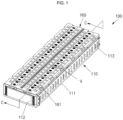
- FIG. 1 is a perspective view of an energy storage module according to an embodiment of the present disclosure
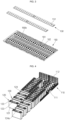
- FIG. 2 is an exploded perspective view of the energy storage module according to an embodiment of the present disclosure
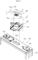
- FIG. 3 is an exploded bottom perspective view of an extinguisher sheet and a top cover of the energy storage module according to an embodiment of the present disclosure
- FIG. 4 is a perspective view illustrating battery cells and insulation spacers arranged on a bottom plate of the energy storage module according to an embodiment of the present disclosure.
- an energy storage module 100 includes a cover member 110, battery cells 120, insulation spacers 130, a top plate 140, an extinguisher sheet 150, and a top cover 160.
- the cover member 110 provides an internal space for receiving (or accommodating) the battery cells 120 and the insulation spacers 130.
- the cover member 110 includes a bottom plate 111, an end plate (or a plurality of end plates) 112, and a side plate (or a plurality of side plates) 113 which together form a space for accommodating the battery cells 120 and the insulation spacers 130.
- the cover member 110 may fix positions of the battery cells 120 and the insulation spacers 130 and may protect the battery cells 120 from external impacts.
- Each of the battery cells 120 is configured such that an electrode assembly is accommodated in a case 121 and the electrode assembly is wound, stacked, or laminated in a state in which a separator is positioned between a positive electrode plate and a negative electrode plate, each having a portion coated with an active material, e.g., a coating portion.
- a top portion of the case 121 may be sealed by a cap plate 124.
- a vent 124a is located at approximately a center of the cap plate 124 and has a smaller thickness than other regions of the cap plate 124.
- electrode terminals 122 and 123 which are electrically connected to uncoated regions (e.g., uncoated portions) of the positive and negative electrode plates, may be exposed at an upper portion of the case 121 through the cap plate 124.
- the electrode terminals 122 and 123 may be referred to as a first electrode terminal 122 and a second electrode terminal 123, respectively, defining, for example, a negative electrode terminal and a positive electrode terminal.
- the polarities of the electrode terminals 122 and 123 may be reversed, defining a positive electrode terminal and a negative electrode terminal, respectively. Occurrences of ignition of the battery cells 120 can be reduced by using particular compositions of active materials of the battery cells 120, thereby increasing safety.
- the insulation spacers 130 may be positioned between each of (e.g., between adjacent ones of) the battery cells 120 to prevent or substantially prevent the battery cells 120 from contacting one another, thereby maintaining the battery cells 120 (e.g., the cases 121 of the battery cells 120) in an electrically isolated state.
- a reference distance or space e.g., a predetermined distance
- the insulation spacers 130 include a flame-retardant (or non-combustible) sheet that prevents (or substantially impedes) a fire from spreading to neighboring battery cells 120, and a heat-insulating sheet that prevents (or substantially impedes) heat from propagating to neighboring battery cells 120 when a fire starts in any of the battery cells 120. Configurations of the insulation spacers 130 will be described in further detail below.
- the top plate 140 is coupled to a top portion (e.g., a top surface or a top) of the cover member 110.
- the top plate 140 may be coupled to the cover member 110 while covering top portions (e.g., top surfaces) of the battery cells 120.
- the first electrode terminals 122 and second electrode terminals 123 of the battery cells 120 are exposed to (or through) the top plate 140, and bus bars 145 are coupled to the respective terminals 122 and 123, thereby connecting the battery cells 120 to one another in series, in parallel, or in series/parallel.
- the top plate 140 includes a plurality of ducts 141 located to respectively correspond to the vents 124a, which are located on the top surface of each of the battery cells 120.
- the ducts 141 may be arranged in a direction, for example, in a length direction of the top plate 140. Accordingly, the gas discharged from the vent 124a of one of the battery cells 120 may move upwardly along a corresponding one of the ducts 141 of the top plate 140.
- a configuration and operation of the ducts 141 will be described in further detail below.
- the extinguisher sheet 150 is positioned between the top plate 140 and the top cover 160.
- the extinguisher sheet 150 may be provided as one or more members (or sheets) extending in a direction, for example, in the length direction, of the top plate 140.
- the extinguisher sheet 150 may include openings (e.g., opening holes) positioned to respectively correspond to the ducts 141 of the top plate 140. Accordingly, the extinguisher sheet 150 may be positioned such that the openings therein are respectively aligned with the ducts 141 of the top plate 140.
- the extinguisher sheet 150 may be coupled to a bottom surface 160b of the top cover 160. Because the extinguisher sheet 150 is coupled to the bottom surface 160b of the top cover 160, the extinguisher sheet 150 may be positioned above the top plate 140. A configuration and operation of the extinguisher sheet 150 will be described below in further detail.
- the top cover 160 is coupled to the top portion of the top plate 140.
- the top cover 160 may cover the top plate 140 and the bus bars 145.
- the top cover 160 also covers the extinguisher sheet 150, which is coupled to the bottom surface 160b of the top cover 160, thereby protecting the top plate 140, the bus bars 145, and the extinguisher sheet 150 from external impacts applied to a top surface 160a of the top cover 160.
- the top cover 160 includes discharge openings (e.g., discharge holes) 161.
- the top cover 160 further includes protrusion parts (e.g., protrusions) 162 spaced a distance apart from the outer periphery of (e.g., extending around a periphery of) respective ones of the discharge holes 161, and the protrusion parts 162 downwardly protrude from the top cover 160.
- Openings (e.g., opening holes) 151 of the extinguisher sheet 150 may be coupled to (e.g., may extend around) the exterior of respective ones of the protrusion parts 162, and the ducts 141 may be coupled to (e.g., may extend into) the interior of the protrusion parts 162.
- the discharge holes 161 may each include a plurality of discharge openings (e.g., discharge sub-openings) arranged in a direction, for example, in a length direction, of the top cover 160.
- the discharge holes 161 may be positioned to respectively correspond to the ducts 141 of the top plate 140.
- the discharge holes 161 may each be provided as a plurality of openings passing through top and bottom surfaces of the top plate 140 and spaced apart from one another.
- the gases discharged from the vent 124a of the battery cell 120 when the vent 124a ruptures may be discharged to the exterior through the corresponding duct 141 of the top plate 140 and the corresponding discharge opening 161 of the top cover 160 and may facilitate user safety by preventing or substantially preventing a user's hand from contacting an internal structure of the top cover 160.
- a rack includes a plurality of shelves and a plurality of the energy storage modules 100 accommodated on the shelves thereof.
- the rack include the plurality of shelves installed to be upwardly spaced apart from one another, and one or more energy storage modules 100 may be accommodated on each of the shelves.
- a bottom surface of one of the energy storage modules 100 may contact a top surface of a first shelf, and a bottom surface of another one of the energy storage modules 100 may be positioned on the top surface of a second shelf while being spaced a distance apart from the top surface of the first shelf.
- FIG. 5 is a partial exploded perspective view illustrating a battery cell, a top plate, and a top cover of the energy storage module 100 according to an embodiment of the present disclosure.
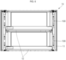
- FIG. 6 partially illustrates a rack on which energy storage modules are coupled according to an embodiment of the present disclosure.
- FIGS. 7A and 7B are cross-sectional views taken along the lines A-A and B-B, respectively, of FIG. 5 ; and
- FIG. 7C is a partial enlarged view of FIG. 7A .
- FIG. 8 is a cross-sectional view of a duct according to an embodiment of the present disclosure.
- the ducts 141 located on the top plate 140 respectively correspond to the vents 124a of the battery cells 120, and the discharge holes 161 of the top cover 160 are positioned to respectively correspond to the ducts 141 of the top plate 140.
- the duct 141 is a passage through which the gas discharged through the vent 124a of the battery cell 120 passes, and protrudes from the top plate 140.
- the duct 141 may have a cross-sectional shape, e.g., an elliptical shape, corresponding to the vent 124a of each of the battery cells 120.
- the duct 141 may taper away from a bottom portion thereof with an inner diameter thereof gradually decreasing upward.
- the duct 141 may have a uniform thickness and may be inclined at an angle (e.g., a predefined angle) ( ⁇ ) toward the interior thereof.
- the angle ( ⁇ ) of inclination of the duct 141 may be in a range from about 1° to about 3°.
- the duct 141 may have a height equivalent to that of the top cover 160.
- the height of the duct 141 may be set to be in a range from 15 mm to 20 mm, and, in an embodiment, in a range from 18 mm to 18.4 mm.
- the gas generated from the vent 124a of the battery cell 120 can be prevented or substantially prevented from returning to the vent 124a, even if the gas collides with the shelf 12 after moving along the duct 141.
- the shelf 12 and the duct 141 can be easily manufactured.
- the gas having gone through the duct 141 may move toward the discharge opening 161 of the top cover 160.
- a duct 141' may taper away from a bottom portion thereof with an inner diameter thereof gradually decreasing upward.
- the duct 141' may be configured to have a thickness gradually decreasing from a bottom portion thereof to a top portion thereof.
- an interior surface of the duct 141' may be gradually upwardly inclined with an angle (e.g., a predefined angle) to the exterior, and an exterior surface of the duct 141' may be gradually upwardly inclined with an angle (e.g., a predefined angle) to the interior.
- an inclination angle of the interior of the duct 141' may be in a range from about 1° to about 5°, and, in an embodiment, in a range from about 1° to about 3°, to allow the gas to be sufficiently discharged without obstructing the operation of the vent 124a of the battery cell 120.
- the inclination angle is greater than or equal to 1°, the gas generated from the vent 124a of the battery cell 120 can be easily accumulated upwardly.
- the inclination angle is less than or equal to 5°, rigidity of the duct 141' can be maintained and upward movement of the gas may be prevented or substantially prevented from being restricted by the duct 141'.
- the top cover 160 may include an exhaust region 161a having a plurality of discharge openings (e.g., discharge holes) 161 located therein, protrusion parts (e.g., protrusions) 162 located on a bottom surface of the top cover 160, and an inclined part 163 located between the exhaust region 161a and each of the protrusion parts 162.
- the exhaust region 161a is positioned on a top portion of the duct 141 and can be defined by a region forming peripheries around the discharge holes 161.
- the exhaust region 161a may have a thickness D2 smaller than a thickness D1 of the top cover 160 (D1>D2).
- the thickness D2 of the exhaust region 161a may be two thirds (2/3) of the thickness D1 of the top cover 160. In an embodiment, the thickness D2 of the exhaust region 161a may be at least 1.0 mm. In this case, injection molding can be properly performed while minimizing or reducing occurrence of flames when the gas is discharged. In an embodiment, for example, when the thickness D1 of the top cover 160 is about 2.5 mm, the thickness D2 of the exhaust region 161a may be set to about 1.5 mm.
- the gas exhausted from the vent 124a of the battery cell 120 may be discharged through the discharge holes 161 in the exhaust region 161a. While three discharge holes 161 are shown in the illustrated embodiment, the number of discharge holes 161 is not limited to three. In an embodiment, the overall area occupied by the plurality of discharge holes 161 may be set to be not less than about 30% of an area of the exhaust region 161a to exhibit good ventilation performance. In an embodiment, a width W1 of each of the discharge holes 161 may be set to be smaller than 3 mm.
- the width W1 of the discharge hole 161 is less than or equal to 3 mm, flames generated in the battery cell 120 may be prevented or substantially prevented from spreading to the exterior and safety can be increased by preventing or substantially preventing a user's hand from directly contacting the battery cell 120 from the exterior of the top cover 160.
- the discharge holes 161 are positioned inside (e.g., within) the duct 141, and a top end of the duct 141 is covered (e.g. surrounded) by the exhaust region 161a.
- an area of the exhaust region 161a where the discharge holes 161 are not located may extend toward the interior of the duct 141.
- a distance D3 of the exhaust region 161a extending toward the interior of the duct 141 may be set to about 2 mm or less, and, in an embodiment, in the range between 1 mm and 1.5 mm.
- the protrusion part 162 may protrude from the bottom surface 160b of the top cover 160 and may be coupled to the exterior of the duct 141.
- the protrusion part 162 may be shaped to correspond to a cross-section of the duct 141 and may cover the exhaust region 161a.
- the protrusion part 162 may have a larger cross-section than the duct 141, and a space may exist between the duct 141 and the protrusion part 162.
- a height D4 of the protrusion part 162 may be in the range of between about 2 mm and about 4 mm, and, in an embodiment, 3 mm. If the height D4 of the protrusion part 162 is smaller than 2 mm, the length of the protrusion part 162 protruding from the bottom surface 160b of the top cover 160 may not be long enough to guide the gases having collided with the exhaust region 161a to the exterior of the duct 141. If the height D4 of the protrusion part 162 is greater than 4 mm, the length of the protrusion part 162 protruding from the bottom surface 160b of the top cover 160 may be excessively large, and the gases may not be efficiently discharged.
- a ratio of the height D4 of the protrusion part 162 to the height of the duct 141 may be about 1:4 to 1:9, and, in an embodiment, 1:6. If the ratio of the height D4 of the protrusion part 162 to the height of the duct 141 is greater than 1:4, the protrusion part 162 may be easily manufactured to cover the top portion of the duct 141. If the ratio of the height D4 of the protrusion part 162 to the height of the duct 141 is less than 1:9, the gases having passed the duct 141 may be easily upwardly guided.
- the inclined part 163 is positioned between the exhaust region 161a and the protrusion part 162.
- the inclined part 163 is configured to be naturally inclined by connecting the exhaust region 161a having a relatively small thickness and the protrusion part 162 in the top cover 160.
- the inclined part 163 may be configured to have a gradually increasing thickness from the exhaust region 161a to the protrusion part 162.
- the top end of the duct 141 is positioned below the inclined part 163.
- the inclined part 163 may serve to prevent or substantially prevent the gases discharged through the vent 124a of the battery cell 120 from being induced back to the vent 124a.
- the gases discharged through the vent 124a of the battery cell 120 may be discharged to the exterior of the duct 141 along the inclined part 163 and the protrusion part 162, even if colliding with the exhaust region 161a extending toward the interior of the duct 141 in the course of upwardly moving along the duct 141. Therefore, since the gases are prevented or substantially prevented from being induced back to the vent 124a of the battery cell 120, the safety of the energy storage module 100 can be improved.
- the inclined part 163 may be configured to have a slope in the range from about 30° to about 60° with respect to the exterior surface of the duct 141, and, in an embodiment, in the range from 40° to 50°.
- the angle of the inclined part 163 with respect to the exterior surface of the duct 141 is greater than 30°, the gases discharged through the vent 124a are allowed to be discharged to the exterior, thereby easily preventing or substantially preventing the discharged gases from being induced back to the vent 124a again. If the angle of the inclined part 163 with respect to the exterior surface of the duct 141 is less than 60°, the inclined part 163 can be advantageously integrated with the protrusion part 162.
- the energy storage module 100 may include a plurality of the energy storage modules to be combined with a rack 10.
- the number of energy storage modules 100 may vary according to the desired capacity, and the energy storage modules 100 may be mounted in the rack 10 and then fixed thereto.
- the rack 10 may include a frame 11 defining the overall external shape of the rack 10 and shelves 12 at different layers of the frame 11 to support bottom portions (e.g., bottom surfaces) of the energy storage modules 100.
- two shelves 12 are shown in the frame 11 with energy storage modules 100 respectively mounted on the shelves 12, but the present disclosure is not limited to the numbers in the illustrated embodiment.
- the vent 124a of a battery cell 120 ruptures, the gas discharged from one of the vents 124a may move upwardly along the duct 141, as indicated by the arrows.
- the vent 124a remaining in the cap plate 124 is shown in FIGS. 7A and 7B .
- the vent 124a may rupture and then be removed.
- some of the discharged gases may move along the inclined part 163 and the protrusion part 162 after colliding with the exhaust region 161a extending toward the interior of the duct 141.
- the gases having passed the duct 141 may move toward the exterior through the discharge holes 161 of the top cover 160 positioned above the duct 141.
- the gases may accumulate between the top surface 160a of the top cover 160 and the adjacent shelf 12 accommodating another energy storage module 100 located above the top surface 160a of the top cover 160.
- a distance between the top surface 160a of the top cover 160 and the adjacent shelf 12 may be in a range from about 3 mm to about 7 mm. When the distance is greater than or equal to about 3 mm, the heat generated from the energy storage module 100 can be easily discharged to the exterior. When the distance is less than or equal to about 7 mm, a high-temperature inert gas atmosphere can be easily created.
- a phase change may begin to occur in a fire extinguishing agent in the extinguisher sheet 150 at a temperature in a range from about 40°C to 60°C, and more specifically, a temperature in a range from 45°C to 55°C.
- the fire extinguishing agent may remain inside the extinguisher sheet 150 instead of being sprayed (released) therefrom.
- a gas containing an electrolytic steam may be generated mainly through the vent.
- the gas in the above temperature range may allow a heat-resistant plastic constituting an upper plate 140 and an upper cover 160 to remain unmelted.
- spraying of some of the fire extinguishing agent may begin.
- the inclined part 163 of the top cover 160 may prevent or substantially prevent the initially generated combustible gas having a relatively low temperature from being induced back into the vent.
- high-temperature inert gas may be generated with flames.
- the inert gas may fill the space between the top surface 160a of the top cover 160 and the adjacent shelf 12 to create an inert gas atmosphere.
- the inert gas may also fill the internal space of the duct 141.
- Such inert gas may prevent or substantially prevent oxygen induction and may prevent or substantially prevent flames generated by the battery cell 120 from spreading to neighboring battery cells 120 or to another energy storage module 100.
- the extinguisher sheet 150 which is positioned under the top cover 160, may operate (e.g., may emit or spray the fire extinguishing agent) in response to the high-temperature inert gas.
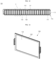
- FIG. 9 is a perspective view of the extinguisher sheet coupled to the top plate of the energy storage module according to an embodiment of the present disclosure
- FIG. 10 is an enlarged view of the region "B" of FIG. 9
- FIGS. 11A and 11B are conceptual diagrams illustrating a state in which an extinguisher sheet operates in the energy storage system according to an embodiment of the present disclosure.
- the extinguisher sheet 150 is positioned between the top plate 140 and the top cover 160. As shown in FIGS. 9 and 10 , the extinguisher sheet 150 may have openings (e.g., opening holes) 151 respectively coupled to (e.g., extending around) the ducts 141 of the top plate 140. Accordingly, movement of gas through the ducts 141 may not be influenced (or substantially influenced) by the extinguisher sheet 150.
- openings e.g., opening holes
- the extinguisher sheet 150 may operate (e.g., may emit the fire extinguishing agent) in response to heat when the inert gas having a relatively high temperature of, for example, about 200 oC, is generated.
- the fire extinguishing agent contained in the extinguisher sheet 150 is emitted by (e.g., is sprayed from) the extinguisher sheet 150 in response to the high-temperature gas.
- the fire extinguishing agent may be directionally emitted (or sprayed) toward a direction away from the bottom surface of the top cover 160.
- the fire extinguishing agent may reach the underlying insulation spacers 130 through openings (e.g., fire extinguishing agent openings or opening holes) 143 located between adjacent ones of the ducts 141 of the top plate 140.
- a fluid guide protrusion 142 may further be provided around the openings 143, thereby efficiently guiding the movement of the fire extinguishing agent toward the insulation spacers 130.
- the fire extinguishing agent may move along surfaces of the insulation spacers 130, thereby extinguishing a fire on a battery cell 120 and cooling the battery cell 120.
- the extinguisher sheet 150 may include a capsule-type fire extinguishing agent received within (e.g., accommodated or stored in) an external case. As described above, the extinguisher sheet 150 may emit the internal fire extinguishing agent such that the capsule-type fire extinguishing agent and the external case open (or rupture) when the gas passing through the duct 141 of the top plate 140 reaches a relatively high temperature of about 200 oC.
- FIG. 12 is a cross-sectional view taken along the line C-C of FIG. 1 .
- FIG. 13 is a perspective view of an insulation spacer in the energy storage module according to an embodiment of the present disclosure.
- FIGS. 14A and 14B are exploded perspective views illustrating example configurations of sheet parts of the insulation spacer shown in FIG. 13 ;
- FIG. 15 is a cross-sectional view taken along the line D-D of FIG. 14A after the sheet parts are adhered to each other; and
- FIG. 16 is an enlarged view of the region "C" of FIG. 12 .
- the battery cells 120 and insulation spacers 130 may be alternately arranged on a top surface of the bottom plate 111 of the cover member 110.
- the battery cells 120 may be arranged such that the long side surface of one of the battery cells 120 is spaced a distance (e.g., a reference or predetermined distance) apart from a long side surface of another (e.g., an adjacent) one of the battery cells 120, and the insulation spacers 130 are positioned between the neighboring battery cells 120.
- the distance (e.g., a first distance) between the long side surfaces of the two neighboring battery cells 120 may be in a range from about 4 mm to about 6 mm.
- the first distance is smaller than 4 mm, it is not easy to provide air layers between the battery cells 120 and the insulation spacers 130, thereby lowering cooling efficiency. If the first distance is greater than 6 mm, the energy storage module 100 may become unnecessarily bulky.
- each of the insulation spacers 130 positioned between each of the battery cells 120 may prevent or substantially prevent the battery cells 120 from contacting each other, thereby maintaining the cases 121 of the battery cells 120 in an electrically isolated state.
- each of the insulation spacers 130 may have a planar size corresponding to that of the long side surface of one battery cell 120.
- one surface of the insulation spacer 130 may face the long side surface of one battery cell 120, and an opposite surface of the insulation spacer 130 may face the long side surface of another battery cell 120.
- the insulation spacer 130 and the long side surface of the battery cell 120 may be spaced apart by a distance (e.g., a second distance) to establish a passage for external air.
- the battery cell 120 may be cooled by the external air passing through the external air passage.
- the insulation spacers 130 may include a sheet part (e.g., a sheet) 131 and an edge part (e.g., an edge) 132.
- the sheet part 131 may include a flame-retardant (or non-combustible) sheet that prevents (or substantially impedes) a fire from spreading to neighboring battery cells 120, and a heat-insulating sheet that prevents (or substantially impedes) heat from being propagated to neighboring battery cells 120 when a fire starts in any of the battery cells 120.
- the sheet part 131 may include a heat-insulating first sheet 131a and a plurality of (e.g., two) flame-retardant (or non-combustible) second sheets 131b adhered to opposite surfaces of the first sheet 131a by one or more adhesion members 131c.
- the sheet part 131 may have an increased heat insulating effect and may provide flame retardancy (and non-combustibility) by stacking multiple layers of the first sheet 131a and the second sheets 131b.
- the insulation spacers 130 may prevent or substantially prevent heat or flames from propagating to neighboring battery cells 120 through the stacked sheet parts 131 when the temperature of the battery cell 120 rises or flames are generated in the battery cell 120.
- the insulation spacers 130 may employ a mixture of a flame-retardant or non-combustible sheet that prevents (or substantially mitigates) flames from spreading to neighboring battery cells 120, and a heat-insulating sheet that prevents (or substantially mitigates) heat from being propagated to neighboring battery cells 120 when a fire starts in any of the battery cells 120. Configurations of the insulation spacers 130 will be described in further detail below.
- the first sheet 131a and the second sheets 131b have the same (or substantially the same) size.
- a thickness of the insulation spacer 130 may not exceed about 50% of the first distance to facilitate movement of the fire extinguishing agent, which will be described in further detail below.
- the first sheet 131a may have a thickness in a range from about 1 mm to about 1.4 mm.
- each of the second sheets 131b may have a thickness in a range from about 0.1 mm to about 0.2 mm, and the adhesion member 131c may have a thickness of about 0.1 mm.
- the first sheet 131a may include (or may be formed of) ceramic paper, and the second sheets 131b may include (or may be formed of) mica paper.
- the first sheet 131a may further include an aerogel.
- the first sheet 131a may include (or may be) ceramic paper made of a fiber-containing refractory insulating material.
- the first sheet 131a may include (or may be) bio-soluble fiber ceramic paper (e.g., a ceramic fiber) containing an alkali earth metal, which is an eco-friendly high-temperature insulating material that is generally harmless to humans.
- the sheet part 131 may have a configuration shown in FIG. 14A or FIG. 14B .
- the adhesion member 131c may be positioned between the opposite ends of the first sheet 131a and each of the second sheets 131b such that the sheet part 131 has a reference (or predetermined) width.
- the adhesion member 131c may attach the first sheet 131a and the second sheets 131b to each other.
- the adhesion member 131c may have a same length as the first sheet 131a and the second sheets 131b in a length direction. For example, opposite ends x1 of the first sheet 131a may be adhered to respective opposite ends x1 of the second sheets 131b by the adhesion member 131c.
- the adhesion member 131c may have a width in a range from about 10 mm to about 20 mm.
- the width of the adhesion member 131c is smaller than about 10 mm, adhesion between the first sheet 131a and the second sheets 131b may be insufficient. If the width of the adhesion member 131c is greater than about 20 mm, an ignition probability may increase due to the adhesion member 131c.
- the adhesion member 131c may include any of general adhesion members comprising a variety of adhesive components or configurations, such as, for example, a double-sided tape or an adhesive tape, but the adhesive components and configurations of the adhesion member 131c are not limited thereto.
- the adhesion member 131c may attach (e.g., may only attach) the opposite ends x1 of the first sheet 131a to the second sheets 131b such that the first sheet 131a and the second sheets 131b are spaced apart from each other at a central portion x2 of the sheet part 131.
- air passages 131d may be established or defined between the first sheet 131a and the second sheets 131b.
- the air passages 131d established at the central portion x2 of the sheet part 131 may reduce (or mitigate) compression of the sheet part 131.
- the adhesion member 131c may be located at an area at (or adjacent to) top and bottom ends of the first sheet 131a to attach the first sheet 131a and the second sheets 131b to each other.
- the adhesion member 131c may have a same width as the first sheet 131a and the second sheets 131b in a width direction.
- the top and bottom ends of the first sheet 131a may be respectively adhered to top and bottom ends of the second sheets 131b by the adhesion member 131c.
- the adhesion member 131c may be attached to the opposite ends of the sheet part 131, as shown in FIG. 14A .
- an adhesion area e.g., a vertical adhesion area
- an adhesion area may be reduced relative to the overall area of the sheet part 131 due to an area occupied by the adhesion member 131c attached to the opposite ends of the sheet part 131, thereby lowering adhesion performance.
- the adhesion member 131c may be applied to (e.g., the first sheet 131a and the second sheets 131b may have a region adhered to each other from) the top and bottom ends thereof to increase the adhesion area, thereby improving the adhesion performance.
- the configuration of the sheet part 131 shown in FIG. 14B may be substantially the same as the sheet part 131 shown in FIGS. 14A and 15 , except for positions of the adhesion member(s) 131c.
- the adhesion member 131c when the adhesion member 131c is applied to the top and bottom ends of the sheet part 131, the adhesion performance is improved, and, in some embodiments, no edge part (described below) may be separately required (e.g., an edge part may be omitted).
- an edge part 132 may be provided along peripheral edges of the sheet part 131.
- the edge part 132 may include (or may be made of) a plastic material, and may be coupled to edges of the sheet part 131 by using a double injection process to fix the shape of the sheet part 131.
- the edge part may be made of a general polyethylene or polypropylene.
- the edge part 132 may have a width in a range from about 3 mm to about 6 mm.
- the width of the edge part 132 is smaller than about 3 mm, the sheet part 131 may not be easily fixed, and, if the width of the edge part 132 is greater than about 6 mm, an ignition probability of the edge part 132 made of a plastic material may be increased.
- the fire extinguishing agent when a fire extinguishing agent is applied from top portions of the insulation spacers 130, the fire extinguishing agent may move downwardly along the surfaces of the sheet part 131. Therefore, the fire extinguishing agent may contact the case 121 of the adjacent battery cells 120, thereby performing extinguishing and cooling operations on the battery cells 120.
- movement of the fire extinguishing agent will be described in further detail.
- the top plate 140 further includes openings (e.g., opening holes) 143 respectively located to correspond to (e.g., located over or above) the insulation spacers 130. Accordingly, the fire extinguishing agent, when emitted from the extinguisher sheet 150, may pass through the top plate 140 through the opening holes 143 of the top plate 140 to reach the insulation spacers 130. In addition, the fire extinguishing agent may move along surfaces of the insulation spacers 130 that face the cases 121 of the adjacent battery cells 120, thereby extinguishing a fire and cooling the battery cells 120.
- openings e.g., opening holes
- the fire extinguishing agent is emitted by the extinguisher sheet 150 located over one or more of the battery cells 120, the temperature of which is higher than a reference temperature. Therefore, the fire extinguishing agent may be sprayed from a top portion of the battery cell 120 having an elevated temperature. In addition, because the fire extinguishing agent moves along the surfaces of the insulation spacers 130 positioned at front and rear sides of the corresponding battery cell 120, both extinguishing and cooling of the corresponding battery cell 120 can be performed.
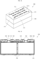
- FIG. 17 is a perspective view of an energy storage module according to another embodiment of the present disclosure
- FIG. 18 is a bottom perspective view of the energy storage module of FIG. 17
- FIG. 19 is a cross-sectional view taken along the line E-E of FIG. 17
- FIG. 20 is a perspective view illustrating battery cells and insulation spacers arranged on a cover member in the energy storage module of FIG. 17 .
- an energy storage module 200 includes a cover member 210, battery cells 120, insulation spacers 230, a top plate 240, an extinguisher sheet 250, and a top cover 260.
- the cover member 210, the top plate 240, the extinguisher sheet 250, and the top cover 260 may be similarly configured to those of the energy storage module 100 described above.
- the battery cells 120 may be the same (or substantially the same) as those of the energy storage module 100. Accordingly, the following description will focus on differences between the energy storage module 200 and the energy storage module 100.
- the cover member 210 may include a bottom plate 211, an end plate (or a plurality of end plates) 212, and a side plate (or a plurality of side plates) 213 which together form a space in which the battery cells 120 and the insulation spacers 230 are alternately arranged on the bottom plate 211.
- the cover member 210 may fix positions of the battery cells 120 and the insulation spacers 230 and may protect the battery cells 120 from external impacts.
- the bottom plate 211 may further include openings (e.g., through-holes) 211a, through which the fire extinguishing agent from the extinguisher sheet 250 and the air moving along the exterior surfaces of the insulation spacers 230 are exhausted.
- the through-holes 211a may be positioned to correspond to the insulation spacers 230.
- the insulation spacers 230 are positioned between adjacent ones of the battery cells 120 to prevent or substantially prevent the battery cells 120 from contacting one another, thereby maintaining the cases 121 of the battery cells 120 in electrically isolated states.
- each of the insulation spacers 230 may have short side surfaces, each having a planar size sufficient to cover (e.g., entirely cover) the long side surfaces of two adjacent battery cells 120.
- one of the insulation spacers 230 may be positioned between each group of four adjacent battery cells 120, which are arranged such that long side surfaces of two of the four battery cells 120 face each other.
- the insulation spacers 230 include (or are made of) a flame-retardant (or non-combustible) sheet that prevents (or substantially mitigates) a fire from spreading to neighboring battery cells and a heat-insulating sheet that prevents (or substantially mitigates) heat from propagating to neighboring battery cells when a fire occurs in any of the battery cells 120.
- a flame-retardant (or non-combustible) sheet that prevents (or substantially mitigates) a fire from spreading to neighboring battery cells
- a heat-insulating sheet that prevents (or substantially mitigates) heat from propagating to neighboring battery cells when a fire occurs in any of the battery cells 120.
- the top plate 240 is coupled to a top portion (e.g., a top surface or a top) of the cover member 210.
- the top plate 240 may be coupled to the cover member 210 while covering top portions of the battery cells 120.
- the top plate 240 includes ducts 241 respectively corresponding to the vents 124a located on a top surface of each of the battery cells 120.
- the ducts 241 may be arranged in a direction, for example, in a length direction of the top plate 240. Accordingly, if the vent 124a of the battery cell 120 ruptures, the gas discharged through the vent 124a may move upwardly along the ducts 241 of the top plate 240. Configurations and operations of the ducts 241 will be described in further detail below.
- the extinguisher sheet 250 is positioned between the top plate 240 and the top cover 260.
- the extinguisher sheet 250 may include a plurality of planar sheets located at opposite sides of the ducts 241 of the top plate 240 and extending in a length direction of the top plate 240.
- the extinguisher sheet 250 may be mounted on a bottom surface 260b of the top cover 260 in the form of a planar sheet extending in the length direction.
- the length direction may refer to a direction in which the ducts 241 of the top plate 240 extend.
- the top cover 260 is coupled to the top portion of the top plate 240.
- the top cover 260 may cover the top plate 240 and the extinguisher sheet 250, thereby protecting the top plate 240 and the extinguisher sheet 250 from external impacts applied to a top surface of the top cover 260.
- the top cover 260 includes discharge openings (e.g., discharge holes) 261.
- the top cover 260 also includes protrusion parts (e.g., protrusions) 262 spaced apart from (e.g. extending around) the outer periphery of respective ones of the discharge holes 261. The protrusion parts 262 may protrude downwardly.
- each of the discharge holes 261 may include a plurality discharge holes arranged in a direction, for example, in a length direction of the top cover 260.
- the discharge holes 261 are positioned to correspond to the ducts 241 of the top plate 240.
- the discharge holes 261 may also be provided as a plurality of openings (e.g., holes) passing through top and bottom surfaces of the top cover 260 and spaced apart from one another. Accordingly, if the vent 124a of the battery cell 120 ruptures, the gas discharged from the vent 124a may be discharged to an exterior side along the duct 241 of the top plate 240 and the discharge holes 261 of the top cover 260.
- top cover 260 may further include openings (e.g., through-holes) 263, through which the fire extinguishing agent of the extinguisher sheet 250 is exhausted and the air moving along the exterior surfaces of the insulation spacers 230 is exhausted.
- the openings 263 may be positioned to respectively correspond to the insulation spacers 230.
- recess parts e.g., recessed portions or recesses
- each having a lower height e.g., a lower height above the battery cells 120
- the discharge holes 261 may be arranged at the recess parts 265.
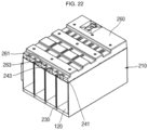
- FIGS. 21A and 21B are a perspective view and an exploded perspective view, respectively, of an insulation spacer in the energy storage module 200; and FIG. 22 is a cross-sectional view taken along the line F-F of FIG. 17 .
- the battery cells 120 and the insulation spacers 230 may be alternately arranged on a top surface of the bottom plate 211 of the cover member 210.
- Each of the insulation spacers 230 may have short side surfaces, each having a planar size sufficient to cover (e.g., entirely cover) long side surfaces of two adjacent battery cells 120.
- one surface of one of the insulation spacers 230 may cover (e.g., entirely cover) the long side surfaces of two adjacent battery cells 120
- the other surface of the one insulation spacer 230 may cover (e.g., entirely cover) the long side surfaces of two other adjacent battery cells 120.
- one of the insulation spacers 230 may be positioned between four battery cells 120 that are arranged such that long side surfaces of two battery cells 120 face long side surfaces of two other battery cells 120.
- long side surfaces of the battery cells 120 may be spaced apart from long side surfaces of facing battery cells 120, and the insulation spacers 230 may be positioned between each of the long side surfaces of the battery cells 120.
- a distance (e.g., a first distance) between the long side surfaces of the facing battery cells 120 may be in a range from about 3.5 mm to about 4.5 mm. If the first distance is smaller than about 3.5 mm, air layers (e.g., air passages) may not be provided between each of the battery cells 120 and the insulation spacers 230, thereby lowering cooling efficiency. If the first distance is greater than about 4.5 mm, the energy storage module 200 may become unnecessarily bulky.
- the insulation spacers 230 may prevent or substantially prevent the battery cells 120 from contacting each other, thereby maintaining the cases 121 of the battery cells 120 in electrically isolated states.
- the insulation spacer 230 and the long side surfaces of battery cells 120 are spaced apart from each other to establish external air passages.
- the battery cells 120 may be cooled by external air moving along (or through) the external air passages.
- the insulation spacers 230 may consist of sheets 231 (e.g., only sheets 231) without separate edge parts.
- the insulation spacers 230 may include a flame-retardant (or non-combustible) sheet that prevents (or substantially mitigates) the fire from spreading to neighboring battery cells 120, and a heat-insulating sheet that prevents (or substantially mitigates) heat from propagating to neighboring battery cells 120.
- the sheet parts 231 of the insulation spacers 230 may include a heat-insulating first sheet 231a and two flame-retardant (or non-combustible) second sheets 231b respectively adhered to opposite surfaces of the first sheet 231a by using one or more adhesion members 231c.
- first sheet 231a and the second sheets 231b have the same (or substantially the same) size.
- a thickness of the insulation spacer 230 may not exceed about 50% of the first distance to facilitate movement of the fire extinguishing agent, which will be described in further detail below.
- An adhesion member 231c may be positioned between the first sheet 231a and the second sheets 231b at a distance (e.g., a reference distance) from top and bottom ends of the first sheet 231a to attach the first sheet 231a and the second sheets 231b to each other.
- the adhesion member 231c may have the same (or substantially the same) width as the first sheet 231a and the second sheets 231b in their width directions.
- the top and bottom ends of the first sheet 231a may be respectively adhered to top and bottom ends of the second sheet 231b by the adhesion member 231c.
- the adhesion member 231c when the sheet part 231 has a width-direction size greater than twice a height-direction size thereof, the adhesion member 231c may be applied to the top and bottom ends thereof to improve adhesion performance.
- the adhesion performance when the sheet part 231 has the width-direction size greater than twice the height-direction size thereof, such as in the embodiment shown in FIG. 21A , the adhesion performance may be lowered when the adhesion member 231c is applied to opposite ends of the sheet part 131, due to a reduction in the adhesion area.
- the insulation spacer 230 may have the same (or substantially the same) configuration as the sheet part 131 described above, as shown in FIG. 21B .
- the fire extinguishing agent may move downwardly along the surfaces of the sheet part 231. Therefore, the fire extinguishing agent may contact the case 121 of the adjacent battery cells 120, thereby extinguishing a fire and cooling the battery cells 120.
- the movement of the fire extinguishing agent and the cooling of the battery cells 120 using the air will be described in further detail.
- the top plate 240 further includes openings (e.g., opening holes) 243 located to respectively correspond to the insulation spacers 230. Accordingly, the fire extinguishing agent emitted from the extinguisher sheet 250 may pass through the top plate 240 through the opening holes 243 of the top plate 240 to reach the insulation spacers 230. In addition, the fire extinguishing agent may move along surfaces of the insulation spacers 230 that face the cases 121 of the battery cells 120, thereby extinguishing and cooling the battery cells 120. The fire extinguishing agent is emitted (or sprayed) from the extinguisher sheet 250 above one or more of the battery cells 120, the temperature of which is higher than a reference temperature.
- openings e.g., opening holes
- the fire extinguishing agent may be sprayed from a top portion of the battery cell 120, the temperature of which has increased.
- the fire extinguishing agent moves along the surfaces of the insulation spacers 230 positioned at front and rear sides of the corresponding battery cell 120, the corresponding battery cell 120 can be both extinguished and cooled.
- top cover 260 may further include openings (e.g., through-holes) 263 that pass through top and bottom surfaces of the top cover 260 and are located to respectively correspond to the opening holes 243.
- openings e.g., through-holes
- the through-holes 263 may respectively correspond to the insulation spacers 230.
- the bottom plate 211 of the cover member 210 may also include openings (e.g., through-holes) 211a located to respectively correspond to the insulation spacers 230.
- openings e.g., through-holes
- air introduced through the through-holes 263 of the top cover 260 and the openings 243 of the top plate 240 may move along spaces provided between the insulation spacers 230 and the battery cells 120 to be discharged through the through-holes 211a of the bottom plate 211.
- the movement of the air e.g., the airflow direction
- air passages may be provided by the through-holes 211a and 263, and the opening holes 243, thereby improving cooling efficiency.
- FIGS. 23A and 23B are a perspective view and a cross-sectional view, respectively, of a battery cell used in the energy storage module according to an embodiment of the present disclosure.
- the battery cell 120 is configured such that an electrode assembly 125 is accommodated in a case 121, and a cap plate 124 covers a top portion of the case 121.
- a vent 124a having a smaller thickness than other regions is located approximately at the center of the cap plate 124.
- a duct 141 of the top plate 140 is located to correspond to a top portion of a vent 124a, as described above.
- the electrode assembly 125 may be electrically connected to a first electrode terminal 122 and a second electrode terminal 123 located on the cap plate 124 through a pair of current collectors 126.
- the first electrode terminal 122 will be referred to as a negative electrode terminal and the second electrode terminal 123 will be referred to as a positive electrode terminal, but polarities thereof may be reversed.
- the electrode assembly 125 may include a negative electrode 125a, a positive electrode 125b positioned to face the negative electrode 125a, and a separator 125c positioned between the negative electrode 125a and the positive electrode 125b, and the electrode assembly 125 may be accommodated in the case 121 together with an electrolyte (not shown).
Landscapes
- Chemical & Material Sciences (AREA)
- Chemical Kinetics & Catalysis (AREA)
- General Chemical & Material Sciences (AREA)
- Electrochemistry (AREA)
- Engineering & Computer Science (AREA)
- Manufacturing & Machinery (AREA)
- Business, Economics & Management (AREA)
- Emergency Management (AREA)
- Health & Medical Sciences (AREA)
- Public Health (AREA)
- Battery Mounting, Suspending (AREA)
Claims (13)
- Energiespeichermodul (100, 200), Folgendes umfassend:eine Vielzahl von Batteriezellen (120), die in einer Längsrichtung angeordnet sind, sodass lange Seitenflächen von angrenzenden der Batteriezellen (120) einander zugewandt sind,eine Vielzahl von Isolationsabstandshaltern (130, 230), wobei mindestens einer der Isolationsabstandshalter (130, 230) zwischen den langen Seitenflächen jedes angrenzenden Paares der Batteriezellen (120) liegt;ein Abdeckelement (110, 210), das einen internen Aufnahmeraum umfasst, der dafür konfiguriert ist, die Batteriezellen (120) und die Isolationsabstandshalter (130, 230) aufzunehmen;eine obere Platte (140), die mit einer Oberseite des Abdeckelements (110, 210) gekoppelt ist, wobei die obere Platte (140) Kanäle (141, 241) umfasst, die jeweils Lüftungsöffnungen (124a) der Batteriezellen (120) entsprechen und Öffnungslöcher (143, 243) aufweisen, die jeweils den Isolationsabstandshaltern (130, 230) entsprechen;eine obere Abdeckung (160, 260), die mit einer Oberseite der oberen Platte (140, 240) gekoppelt ist und Auslasslöcher (161, 261) aufweist, die jeweils den Kanälen (141, 241) entsprechen; undeine Löschfolie (150, 250) zwischen der oberen Abdeckung (160, 260) und der oberen Platte (140, 240), wobei die Löschfolie (150, 250) dafür konfiguriert ist, bei einer Temperatur, die eine Referenztemperatur überschreitet, ein Feuerlöschmittel abzugeben,wobei die obere Abdeckung (160, 260) Vorsprungsteile (162, 262) auf einer Unterfläche (160b, 260b) davon umfasst, wobei die Vorsprungsteile (162, 262) einen Auslassbereich (161a) abdecken und mit einer Außenseite jedes der Kanäle (141, 241) gekoppelt sind, und jeder der Isolationsabstandshalter (130, 230) eine wärmeisolierende erste Folie (131a, 231a) und flammhemmende oder nicht brennbare zweite Folien (131b, 231b) umfasst, die jeweils durch ein Klebeelement (131c, 231c) an gegenüberliegende Oberflächen der ersten Folie (131a, 231a) geklebt sind, undwobei die langen Seitenflächen der angrenzenden Batteriezellen (120) um einen ersten Abstand voneinander beabstandet sind, undwobei eine Dicke jedes der Isolationsabstandshalter (130, 230) weniger als 50 % des ersten Abstands beträgt.
- Energiespeichermodul (100, 200) nach Anspruch 1, wobei die erste Folie (131a, 231a) keramisches Papier umfasst und die zweiten Folien (131b, 231b) Glimmerpapier umfassen.
- Energiespeichermodul (100, 200) nach Anspruch 1 oder Anspruch 2, wobei die erste Folie (131a, 231a) eine keramische Faser umfasst, die ein Erdalkalimetall umfasst.
- Energiespeichermodul (100, 200) nach einem der Ansprüche 1 bis 3, wobei, wenn das Feuerlöschmittel aus der Löschfolie (150, 250) abgegeben wird, das Feuerlöschmittel durch die Öffnungslöcher (143, 243) in Räume zwischen den Isolationsabstandshaltern (130, 230) und den Batteriezellen (120) zugeführt wird, um mit den langen Seitenflächen der Batteriezellen (120) in Berührung gebracht zu werden.
- Energiespeichermodul (100) nach einem der Ansprüche 1 bis 4, wobei jeder der Isolationsabstandshalter (130) eine Größe in Breitenrichtung hat, die kleiner als das Doppelte einer Größe in Höhenrichtung davon ist, und einen Folienteil (131) umfasst, der die erste Folie (131a) und die zweiten Folien (131b) umfasst, die an gegenüberliegenden Enden (×1) davon durch das Klebeelement (131c) miteinander verklebt sind.
- Energiespeichermodul (100) nach Anspruch 5, wobei jeder der Isolationsabstandshalter (130) ferner einen Randteil (132), der aus einem Kunststoffmaterial hergestellt ist, umfasst, wobei der Randteil (132) durch Einsatz-Spritzgießen gebildet ist, um Umfangsränder des Folienteils (131) abzudecken.
- Energiespeichermodul (100) nach Anspruch 5 oder Anspruch 6, wobei die erste Folie (131a) und die zweiten Folien (131b) an zentralen Abschnitten (x2) davon voneinander beabstandet sind, um Luftdurchgänge (131d) zu definieren, um Luftbewegung zu ermöglichen.
- Energiespeichermodul (100, 200) nach einem der Ansprüche 1 bis 4, wobei eine Größe in Breitenrichtung jedes der Isolationsabstandshalter (130, 230) größer als das Doppelte einer Größe in Höhenrichtung davon ist, und
wobei die erste Folie (131a, 231a) und die zweiten Folien (131b, 231b) jeweils Bereiche umfassen, die durch das Klebeelement (131c, 231c) miteinander verklebt sind. - Energiespeichermodul (100) nach einem der Ansprüche 1 bis 8, wobei die obere Abdeckung (160) ferner einen abgeschrägten Teil (163) umfasst, um eine allmählich zunehmende Dicke vom Auslassbereich (161a) aus zum Vorsprungsteil (162) aufzuweisen.
- Energiespeichermodul (100) nach Anspruch 9, wobei sich ein oberes Ende jedes der Kanäle (141) unterhalb des abgeschrägten Teils (163) befindet.
- Energiespeichermodul (100) nach Anspruch 9 oder Anspruch 10, wobei ein Raum zwischen jedem der Kanäle (141) und einem entsprechenden der Vorsprungsteile (162) definiert ist.
- Energiespeichermodul (100, 200) nach einem der Ansprüche 1 bis 12, wobei sich jeder der Kanäle (141, 141', 241) von einem Unterteil davon aus verjüngt, wobei ein Innendurchmesser davon nach oben hin allmählich abnimmt.
- Energiespeichermodul (100) nach einem der Ansprüche 1 bis 12, wobei eine Gesamtfläche, die von den Auslassöffnungen (161) eingenommen wird, nicht weniger als etwa 30 % einer Fläche des Auslassbereichs (161a) beträgt.
Applications Claiming Priority (1)
| Application Number | Priority Date | Filing Date | Title |
|---|---|---|---|
| KR1020190110366 | 2019-09-05 |
Publications (2)
| Publication Number | Publication Date |
|---|---|
| EP3790102A1 EP3790102A1 (de) | 2021-03-10 |
| EP3790102B1 true EP3790102B1 (de) | 2024-11-13 |
Family
ID=72380989
Family Applications (1)
| Application Number | Title | Priority Date | Filing Date |
|---|---|---|---|
| EP20194594.6A Active EP3790102B1 (de) | 2019-09-05 | 2020-09-04 | Energiespeichermodul |
Country Status (6)
| Country | Link |
|---|---|
| US (1) | US11145933B2 (de) |
| EP (1) | EP3790102B1 (de) |
| KR (1) | KR102833666B1 (de) |
| CN (2) | CN112448078B (de) |
| HU (1) | HUE069370T2 (de) |
| PL (1) | PL3790102T3 (de) |
Families Citing this family (27)
| Publication number | Priority date | Publication date | Assignee | Title |
|---|---|---|---|---|
| US11728541B2 (en) | 2019-09-05 | 2023-08-15 | Samsung Sdi Co., Ltd. | Energy storage module |
| US20230395934A1 (en) * | 2019-09-05 | 2023-12-07 | Samsung Sdi Co., Ltd. | Energy storage module having an extinguisher sheet |
| US11569546B2 (en) | 2019-09-05 | 2023-01-31 | Samsung Sdi Co., Ltd. | Energy storage module |
| US11735795B2 (en) | 2019-09-05 | 2023-08-22 | Samsung Sdi Co., Ltd. | Energy storage module |
| US12300848B2 (en) | 2019-09-05 | 2025-05-13 | Samsung Sdi Co., Ltd. | Energy storage module including extinguisher sheet |
| US12090354B2 (en) * | 2019-09-05 | 2024-09-17 | Samsung Sdi Co., Ltd. | Energy storage module |
| US11764430B2 (en) | 2019-09-05 | 2023-09-19 | Samsung Sdi Co., Ltd. | Energy storage module |
| US12288895B2 (en) | 2019-09-05 | 2025-04-29 | Samsung Sdi Co., Ltd. | Energy storage module |
| US11799167B2 (en) | 2019-09-05 | 2023-10-24 | Samsung Sdi Co., Ltd. | Energy storage module having extinguisher sheet |
| US11771935B2 (en) * | 2019-09-05 | 2023-10-03 | Samsung Sdi Co., Ltd. | Energy storage module |
| US12057598B2 (en) | 2019-09-05 | 2024-08-06 | Samsung Sdi Co., Ltd. | Energy storage module including extinguisher sheet |
| US11764438B2 (en) | 2019-09-05 | 2023-09-19 | Samsung Sdi Co., Ltd. | Energy storage module having extinguisher sheet |
| US12355098B2 (en) | 2019-09-05 | 2025-07-08 | Samsung Sdi Co., Ltd. | Energy storage module |
| US11848461B2 (en) | 2019-09-05 | 2023-12-19 | Samsung Sdi Co., Ltd. | Energy storage module |
| US11735788B2 (en) | 2019-09-05 | 2023-08-22 | Samsung Sdi Co., Ltd. | Energy storage module including insulation spacers and an extinguisher sheet |
| CN112952243B (zh) * | 2020-11-16 | 2023-03-28 | 江苏时代新能源科技有限公司 | 端盖组件、电池单体及排气方法、电池及用电装置 |
| CN113471588B (zh) * | 2021-06-30 | 2022-10-11 | 中国第一汽车股份有限公司 | 一种上箱体总成、电池总成及电动车辆 |
| KR20230064246A (ko) * | 2021-11-03 | 2023-05-10 | 주식회사 엘지에너지솔루션 | 전지 모듈 및 이를 포함하는 전지 팩 |
| KR102811031B1 (ko) * | 2021-12-24 | 2025-05-23 | 주식회사 엘지에너지솔루션 | 안전성이 강화된 배터리 어셈블리 |
| JP7642843B2 (ja) * | 2021-12-24 | 2025-03-10 | エルジー エナジー ソリューション リミテッド | 安全性が強化されたバッテリーアセンブリ |
| CN115832604B (zh) * | 2022-08-12 | 2026-03-03 | 江苏时代新能源科技有限公司 | 电池单体、电池及用电设备 |
| JP2024546809A (ja) * | 2022-08-31 | 2024-12-26 | エルジー エナジー ソリューション リミテッド | バッテリーパック、バッテリーモジュール及びこれを含む自動車 |
| DE102022125672A1 (de) | 2022-10-05 | 2024-04-11 | Audi Aktiengesellschaft | Moduldeckel für ein Batteriemodul, Batteriemodul und Verfahren zum Herstellen eines Moduldeckels |
| KR20240148594A (ko) * | 2023-04-04 | 2024-10-11 | 삼성에스디아이 주식회사 | 배터리 모듈 |
| KR102613036B1 (ko) * | 2023-07-20 | 2023-12-12 | (주)연호상사 | 배터리 모듈 |
| KR20250140906A (ko) * | 2024-03-19 | 2025-09-26 | 주식회사 엘지에너지솔루션 | 배터리 모듈 |
| KR20250149449A (ko) * | 2024-04-09 | 2025-10-16 | 삼성에스디아이 주식회사 | 배터리 팩 소화장치 |
Family Cites Families (17)
| Publication number | Priority date | Publication date | Assignee | Title |
|---|---|---|---|---|
| KR101067627B1 (ko) | 2006-11-13 | 2011-09-26 | 주식회사 엘지화학 | 콤팩트한 구조와 우수한 방열 특성의 전지모듈 |
| US9263713B2 (en) * | 2010-05-26 | 2016-02-16 | Samsung Sdi Co., Ltd. | Battery pack |
| KR101191660B1 (ko) | 2010-11-08 | 2012-10-17 | 에스비리모티브 주식회사 | 전지 모듈 |
| KR101199148B1 (ko) | 2011-04-21 | 2012-11-09 | 에스비리모티브 주식회사 | 배터리 모듈 |
| US9466819B2 (en) * | 2012-03-07 | 2016-10-11 | Samsung Sdi Co., Ltd. | Battery module |
| CN102861398B (zh) * | 2012-09-24 | 2015-03-18 | 杭州蒙龙机械有限公司 | 一种电池箱灭火装置 |
| US9627663B2 (en) | 2013-04-25 | 2017-04-18 | Samsung Sdi Co., Ltd. | Rechargeable battery pack including pack cover |
| JP6245038B2 (ja) | 2014-03-31 | 2017-12-13 | 株式会社Gsユアサ | 蓄電装置 |
| KR20160021325A (ko) | 2014-08-14 | 2016-02-25 | (주)대한솔루션 | 차량용 배터리 인슐레이션 |
| JP6390062B2 (ja) | 2014-12-08 | 2018-09-19 | 三菱重工業株式会社 | 電池モジュール |
| KR20160146349A (ko) | 2015-06-12 | 2016-12-21 | 동아전장주식회사 | 배터리용 방열 플레이트 |
| WO2018131221A1 (ja) * | 2017-01-13 | 2018-07-19 | 株式会社村田製作所 | 電池トレイ用フタ、フタ付き電池トレイおよび電池の製造方法 |
| CN107093686B (zh) * | 2017-04-28 | 2020-04-14 | 北京新能源汽车股份有限公司 | 电池包和车辆 |
| CN207199806U (zh) | 2017-08-29 | 2018-04-06 | 合肥国轩高科动力能源有限公司 | 一种减缓电池热失控传播的隔热片 |
| CN109585726B (zh) | 2017-09-29 | 2024-03-01 | 宇通客车股份有限公司 | 车辆及其电池箱、电池模组、灭火部件、灭火容器 |
| KR102152886B1 (ko) | 2017-12-11 | 2020-09-07 | 삼성에스디아이 주식회사 | 배터리 팩 |
| CN207977389U (zh) | 2018-01-29 | 2018-10-16 | 浙江美都海创锂电科技有限公司 | 一种安全防爆方形电池模块 |
-
2020
- 2020-06-15 US US16/901,547 patent/US11145933B2/en active Active
- 2020-09-04 KR KR1020200113376A patent/KR102833666B1/ko active Active
- 2020-09-04 CN CN202010921351.1A patent/CN112448078B/zh active Active
- 2020-09-04 HU HUE20194594A patent/HUE069370T2/hu unknown
- 2020-09-04 CN CN202310187488.2A patent/CN116031552A/zh active Pending
- 2020-09-04 PL PL20194594.6T patent/PL3790102T3/pl unknown
- 2020-09-04 EP EP20194594.6A patent/EP3790102B1/de active Active
Also Published As
| Publication number | Publication date |
|---|---|
| CN116031552A (zh) | 2023-04-28 |
| HUE069370T2 (hu) | 2025-02-28 |
| CN112448078A (zh) | 2021-03-05 |
| KR102833666B1 (ko) | 2025-07-14 |
| KR20210029131A (ko) | 2021-03-15 |
| PL3790102T3 (pl) | 2025-02-24 |
| US11145933B2 (en) | 2021-10-12 |
| EP3790102A1 (de) | 2021-03-10 |
| CN112448078B (zh) | 2023-03-14 |
| US20210074974A1 (en) | 2021-03-11 |
Similar Documents
| Publication | Publication Date | Title |
|---|---|---|
| EP3790102B1 (de) | Energiespeichermodul | |
| EP3800727A1 (de) | Energiespeichermodul | |
| EP3790101B1 (de) | Energiespeichermodul | |
| EP3790106B1 (de) | Energiespeichermodul | |
| US12057598B2 (en) | Energy storage module including extinguisher sheet | |
| US20240269496A1 (en) | Energy storage module | |
| US20250096410A1 (en) | Energy storage module | |
| JP2022523777A (ja) | 電池モジュール及び電池パック | |
| KR20210029123A (ko) | 에너지 저장 모듈 | |
| US11771935B2 (en) | Energy storage module | |
| US12355098B2 (en) | Energy storage module | |
| KR20210029125A (ko) | 에너지 저장 모듈 | |
| KR102939515B1 (ko) | 에너지 저장 모듈 | |
| KR20260055331A (ko) | 에너지 저장 모듈 | |
| CN223427727U (zh) | 电池包及用电设备 | |
| KR102833663B1 (ko) | 에너지 저장 모듈 |
Legal Events
| Date | Code | Title | Description |
|---|---|---|---|
| PUAI | Public reference made under article 153(3) epc to a published international application that has entered the european phase |
Free format text: ORIGINAL CODE: 0009012 |
|
| STAA | Information on the status of an ep patent application or granted ep patent |
Free format text: STATUS: REQUEST FOR EXAMINATION WAS MADE |
|
| 17P | Request for examination filed |
Effective date: 20200904 |
|
| AK | Designated contracting states |
Kind code of ref document: A1 Designated state(s): AL AT BE BG CH CY CZ DE DK EE ES FI FR GB GR HR HU IE IS IT LI LT LU LV MC MK MT NL NO PL PT RO RS SE SI SK SM TR |
|
| AX | Request for extension of the european patent |
Extension state: BA ME |
|
| GRAP | Despatch of communication of intention to grant a patent |
Free format text: ORIGINAL CODE: EPIDOSNIGR1 |
|
| STAA | Information on the status of an ep patent application or granted ep patent |
Free format text: STATUS: GRANT OF PATENT IS INTENDED |
|
| INTG | Intention to grant announced |
Effective date: 20240610 |
|
| GRAS | Grant fee paid |
Free format text: ORIGINAL CODE: EPIDOSNIGR3 |
|
| GRAA | (expected) grant |
Free format text: ORIGINAL CODE: 0009210 |
|
| STAA | Information on the status of an ep patent application or granted ep patent |
Free format text: STATUS: THE PATENT HAS BEEN GRANTED |
|
| AK | Designated contracting states |
Kind code of ref document: B1 Designated state(s): AL AT BE BG CH CY CZ DE DK EE ES FI FR GB GR HR HU IE IS IT LI LT LU LV MC MK MT NL NO PL PT RO RS SE SI SK SM TR |
|
| REG | Reference to a national code |
Ref country code: GB Ref legal event code: FG4D |
|
| REG | Reference to a national code |
Ref country code: CH Ref legal event code: EP |
|
| REG | Reference to a national code |
Ref country code: IE Ref legal event code: FG4D |
|
| REG | Reference to a national code |
Ref country code: DE Ref legal event code: R096 Ref document number: 602020041206 Country of ref document: DE |
|
| REG | Reference to a national code |
Ref country code: SE Ref legal event code: TRGR |
|
| REG | Reference to a national code |
Ref country code: HU Ref legal event code: AG4A Ref document number: E069370 Country of ref document: HU |
|
| REG | Reference to a national code |
Ref country code: LT Ref legal event code: MG9D |
|
| REG | Reference to a national code |
Ref country code: NL Ref legal event code: MP Effective date: 20241113 |
|
| PG25 | Lapsed in a contracting state [announced via postgrant information from national office to epo] |
Ref country code: HR Free format text: LAPSE BECAUSE OF FAILURE TO SUBMIT A TRANSLATION OF THE DESCRIPTION OR TO PAY THE FEE WITHIN THE PRESCRIBED TIME-LIMIT Effective date: 20241113 Ref country code: PT Free format text: LAPSE BECAUSE OF FAILURE TO SUBMIT A TRANSLATION OF THE DESCRIPTION OR TO PAY THE FEE WITHIN THE PRESCRIBED TIME-LIMIT Effective date: 20250313 Ref country code: IS Free format text: LAPSE BECAUSE OF FAILURE TO SUBMIT A TRANSLATION OF THE DESCRIPTION OR TO PAY THE FEE WITHIN THE PRESCRIBED TIME-LIMIT Effective date: 20250313 |
|
| PG25 | Lapsed in a contracting state [announced via postgrant information from national office to epo] |
Ref country code: FI Free format text: LAPSE BECAUSE OF FAILURE TO SUBMIT A TRANSLATION OF THE DESCRIPTION OR TO PAY THE FEE WITHIN THE PRESCRIBED TIME-LIMIT Effective date: 20241113 Ref country code: NL Free format text: LAPSE BECAUSE OF FAILURE TO SUBMIT A TRANSLATION OF THE DESCRIPTION OR TO PAY THE FEE WITHIN THE PRESCRIBED TIME-LIMIT Effective date: 20241113 |
|
| PG25 | Lapsed in a contracting state [announced via postgrant information from national office to epo] |
Ref country code: BG Free format text: LAPSE BECAUSE OF FAILURE TO SUBMIT A TRANSLATION OF THE DESCRIPTION OR TO PAY THE FEE WITHIN THE PRESCRIBED TIME-LIMIT Effective date: 20241113 |
|
| PG25 | Lapsed in a contracting state [announced via postgrant information from national office to epo] |
Ref country code: ES Free format text: LAPSE BECAUSE OF FAILURE TO SUBMIT A TRANSLATION OF THE DESCRIPTION OR TO PAY THE FEE WITHIN THE PRESCRIBED TIME-LIMIT Effective date: 20241113 |
|
| PG25 | Lapsed in a contracting state [announced via postgrant information from national office to epo] |
Ref country code: NO Free format text: LAPSE BECAUSE OF FAILURE TO SUBMIT A TRANSLATION OF THE DESCRIPTION OR TO PAY THE FEE WITHIN THE PRESCRIBED TIME-LIMIT Effective date: 20250213 |
|
| PG25 | Lapsed in a contracting state [announced via postgrant information from national office to epo] |
Ref country code: LV Free format text: LAPSE BECAUSE OF FAILURE TO SUBMIT A TRANSLATION OF THE DESCRIPTION OR TO PAY THE FEE WITHIN THE PRESCRIBED TIME-LIMIT Effective date: 20241113 Ref country code: GR Free format text: LAPSE BECAUSE OF FAILURE TO SUBMIT A TRANSLATION OF THE DESCRIPTION OR TO PAY THE FEE WITHIN THE PRESCRIBED TIME-LIMIT Effective date: 20250214 |
|
| PG25 | Lapsed in a contracting state [announced via postgrant information from national office to epo] |
Ref country code: RS Free format text: LAPSE BECAUSE OF FAILURE TO SUBMIT A TRANSLATION OF THE DESCRIPTION OR TO PAY THE FEE WITHIN THE PRESCRIBED TIME-LIMIT Effective date: 20250213 |
|
| PG25 | Lapsed in a contracting state [announced via postgrant information from national office to epo] |
Ref country code: SM Free format text: LAPSE BECAUSE OF FAILURE TO SUBMIT A TRANSLATION OF THE DESCRIPTION OR TO PAY THE FEE WITHIN THE PRESCRIBED TIME-LIMIT Effective date: 20241113 |
|
| PG25 | Lapsed in a contracting state [announced via postgrant information from national office to epo] |
Ref country code: DK Free format text: LAPSE BECAUSE OF FAILURE TO SUBMIT A TRANSLATION OF THE DESCRIPTION OR TO PAY THE FEE WITHIN THE PRESCRIBED TIME-LIMIT Effective date: 20241113 |
|
| PG25 | Lapsed in a contracting state [announced via postgrant information from national office to epo] |
Ref country code: EE Free format text: LAPSE BECAUSE OF FAILURE TO SUBMIT A TRANSLATION OF THE DESCRIPTION OR TO PAY THE FEE WITHIN THE PRESCRIBED TIME-LIMIT Effective date: 20241113 |
|
| PG25 | Lapsed in a contracting state [announced via postgrant information from national office to epo] |
Ref country code: RO Free format text: LAPSE BECAUSE OF FAILURE TO SUBMIT A TRANSLATION OF THE DESCRIPTION OR TO PAY THE FEE WITHIN THE PRESCRIBED TIME-LIMIT Effective date: 20241113 |
|
| PG25 | Lapsed in a contracting state [announced via postgrant information from national office to epo] |
Ref country code: SK Free format text: LAPSE BECAUSE OF FAILURE TO SUBMIT A TRANSLATION OF THE DESCRIPTION OR TO PAY THE FEE WITHIN THE PRESCRIBED TIME-LIMIT Effective date: 20241113 |
|
| PG25 | Lapsed in a contracting state [announced via postgrant information from national office to epo] |
Ref country code: CZ Free format text: LAPSE BECAUSE OF FAILURE TO SUBMIT A TRANSLATION OF THE DESCRIPTION OR TO PAY THE FEE WITHIN THE PRESCRIBED TIME-LIMIT Effective date: 20241113 |
|
| PG25 | Lapsed in a contracting state [announced via postgrant information from national office to epo] |
Ref country code: IT Free format text: LAPSE BECAUSE OF FAILURE TO SUBMIT A TRANSLATION OF THE DESCRIPTION OR TO PAY THE FEE WITHIN THE PRESCRIBED TIME-LIMIT Effective date: 20241113 |
|
| REG | Reference to a national code |
Ref country code: DE Ref legal event code: R097 Ref document number: 602020041206 Country of ref document: DE |
|
| PLBE | No opposition filed within time limit |
Free format text: ORIGINAL CODE: 0009261 |
|
| STAA | Information on the status of an ep patent application or granted ep patent |
Free format text: STATUS: NO OPPOSITION FILED WITHIN TIME LIMIT |
|
| PGFP | Annual fee paid to national office [announced via postgrant information from national office to epo] |
Ref country code: DE Payment date: 20250902 Year of fee payment: 6 |
|
| PGFP | Annual fee paid to national office [announced via postgrant information from national office to epo] |
Ref country code: PL Payment date: 20250829 Year of fee payment: 6 |
|
| REG | Reference to a national code |
Ref country code: AT Ref legal event code: UEP Ref document number: 1742396 Country of ref document: AT Kind code of ref document: T Effective date: 20241113 |
|
| PGFP | Annual fee paid to national office [announced via postgrant information from national office to epo] |
Ref country code: HU Payment date: 20250929 Year of fee payment: 6 Ref country code: GB Payment date: 20250904 Year of fee payment: 6 |
|
| PGFP | Annual fee paid to national office [announced via postgrant information from national office to epo] |
Ref country code: FR Payment date: 20250908 Year of fee payment: 6 Ref country code: AT Payment date: 20250909 Year of fee payment: 6 |
|
| PGFP | Annual fee paid to national office [announced via postgrant information from national office to epo] |
Ref country code: SE Payment date: 20250910 Year of fee payment: 6 |
|
| 26N | No opposition filed |
Effective date: 20250814 |