EP3789625A1 - Agencement de bride, moyeu à bride, moyen d'arrêt, transmission, moteur électrique, éolienne et application industrielle - Google Patents
Agencement de bride, moyeu à bride, moyen d'arrêt, transmission, moteur électrique, éolienne et application industrielle Download PDFInfo
- Publication number
- EP3789625A1 EP3789625A1 EP19195930.3A EP19195930A EP3789625A1 EP 3789625 A1 EP3789625 A1 EP 3789625A1 EP 19195930 A EP19195930 A EP 19195930A EP 3789625 A1 EP3789625 A1 EP 3789625A1
- Authority
- EP
- European Patent Office
- Prior art keywords
- flange
- locking means
- designed
- hub
- power shaft
- Prior art date
- Legal status (The legal status is an assumption and is not a legal conclusion. Google has not performed a legal analysis and makes no representation as to the accuracy of the status listed.)
- Granted
Links
- 230000005540 biological transmission Effects 0.000 claims abstract description 26
- 239000007787 solid Substances 0.000 claims description 4
- 238000012423 maintenance Methods 0.000 description 5
- 239000004568 cement Substances 0.000 description 2
- 238000004519 manufacturing process Methods 0.000 description 2
- 230000007246 mechanism Effects 0.000 description 2
- 230000008439 repair process Effects 0.000 description 2
- 239000011435 rock Substances 0.000 description 2
- 240000000111 Saccharum officinarum Species 0.000 description 1
- 235000007201 Saccharum officinarum Nutrition 0.000 description 1
- 238000002485 combustion reaction Methods 0.000 description 1
- 230000000295 complement effect Effects 0.000 description 1
- 238000010276 construction Methods 0.000 description 1
- 210000003746 feather Anatomy 0.000 description 1
- 230000006872 improvement Effects 0.000 description 1
- 230000010354 integration Effects 0.000 description 1
- 238000000034 method Methods 0.000 description 1
- 238000003825 pressing Methods 0.000 description 1
- 230000008569 process Effects 0.000 description 1
- 230000004044 response Effects 0.000 description 1
- 238000000926 separation method Methods 0.000 description 1
Images


Classifications
-
- F—MECHANICAL ENGINEERING; LIGHTING; HEATING; WEAPONS; BLASTING
- F16—ENGINEERING ELEMENTS AND UNITS; GENERAL MEASURES FOR PRODUCING AND MAINTAINING EFFECTIVE FUNCTIONING OF MACHINES OR INSTALLATIONS; THERMAL INSULATION IN GENERAL
- F16D—COUPLINGS FOR TRANSMITTING ROTATION; CLUTCHES; BRAKES
- F16D1/00—Couplings for rigidly connecting two coaxial shafts or other movable machine elements
- F16D1/06—Couplings for rigidly connecting two coaxial shafts or other movable machine elements for attachment of a member on a shaft or on a shaft-end
- F16D1/08—Couplings for rigidly connecting two coaxial shafts or other movable machine elements for attachment of a member on a shaft or on a shaft-end with clamping hub; with hub and longitudinal key
- F16D1/0852—Couplings for rigidly connecting two coaxial shafts or other movable machine elements for attachment of a member on a shaft or on a shaft-end with clamping hub; with hub and longitudinal key with radial clamping between the mating surfaces of the hub and shaft
- F16D1/087—Couplings for rigidly connecting two coaxial shafts or other movable machine elements for attachment of a member on a shaft or on a shaft-end with clamping hub; with hub and longitudinal key with radial clamping between the mating surfaces of the hub and shaft due to other loading elements in the hub or shaft
-
- F—MECHANICAL ENGINEERING; LIGHTING; HEATING; WEAPONS; BLASTING
- F16—ENGINEERING ELEMENTS AND UNITS; GENERAL MEASURES FOR PRODUCING AND MAINTAINING EFFECTIVE FUNCTIONING OF MACHINES OR INSTALLATIONS; THERMAL INSULATION IN GENERAL
- F16D—COUPLINGS FOR TRANSMITTING ROTATION; CLUTCHES; BRAKES
- F16D1/00—Couplings for rigidly connecting two coaxial shafts or other movable machine elements
- F16D1/06—Couplings for rigidly connecting two coaxial shafts or other movable machine elements for attachment of a member on a shaft or on a shaft-end
-
- F—MECHANICAL ENGINEERING; LIGHTING; HEATING; WEAPONS; BLASTING
- F03—MACHINES OR ENGINES FOR LIQUIDS; WIND, SPRING, OR WEIGHT MOTORS; PRODUCING MECHANICAL POWER OR A REACTIVE PROPULSIVE THRUST, NOT OTHERWISE PROVIDED FOR
- F03D—WIND MOTORS
- F03D15/00—Transmission of mechanical power
- F03D15/10—Transmission of mechanical power using gearing not limited to rotary motion, e.g. with oscillating or reciprocating members
-
- F—MECHANICAL ENGINEERING; LIGHTING; HEATING; WEAPONS; BLASTING
- F01—MACHINES OR ENGINES IN GENERAL; ENGINE PLANTS IN GENERAL; STEAM ENGINES
- F01D—NON-POSITIVE DISPLACEMENT MACHINES OR ENGINES, e.g. STEAM TURBINES
- F01D25/00—Component parts, details, or accessories, not provided for in, or of interest apart from, other groups
- F01D25/24—Casings; Casing parts, e.g. diaphragms, casing fastenings
- F01D25/243—Flange connections; Bolting arrangements
-
- F—MECHANICAL ENGINEERING; LIGHTING; HEATING; WEAPONS; BLASTING
- F03—MACHINES OR ENGINES FOR LIQUIDS; WIND, SPRING, OR WEIGHT MOTORS; PRODUCING MECHANICAL POWER OR A REACTIVE PROPULSIVE THRUST, NOT OTHERWISE PROVIDED FOR
- F03D—WIND MOTORS
- F03D9/00—Adaptations of wind motors for special use; Combinations of wind motors with apparatus driven thereby; Wind motors specially adapted for installation in particular locations
- F03D9/20—Wind motors characterised by the driven apparatus
- F03D9/25—Wind motors characterised by the driven apparatus the apparatus being an electrical generator
-
- F—MECHANICAL ENGINEERING; LIGHTING; HEATING; WEAPONS; BLASTING
- F16—ENGINEERING ELEMENTS AND UNITS; GENERAL MEASURES FOR PRODUCING AND MAINTAINING EFFECTIVE FUNCTIONING OF MACHINES OR INSTALLATIONS; THERMAL INSULATION IN GENERAL
- F16D—COUPLINGS FOR TRANSMITTING ROTATION; CLUTCHES; BRAKES
- F16D1/00—Couplings for rigidly connecting two coaxial shafts or other movable machine elements
- F16D1/06—Couplings for rigidly connecting two coaxial shafts or other movable machine elements for attachment of a member on a shaft or on a shaft-end
- F16D1/076—Couplings for rigidly connecting two coaxial shafts or other movable machine elements for attachment of a member on a shaft or on a shaft-end by clamping together two faces perpendicular to the axis of rotation, e.g. with bolted flanges
-
- F—MECHANICAL ENGINEERING; LIGHTING; HEATING; WEAPONS; BLASTING
- F16—ENGINEERING ELEMENTS AND UNITS; GENERAL MEASURES FOR PRODUCING AND MAINTAINING EFFECTIVE FUNCTIONING OF MACHINES OR INSTALLATIONS; THERMAL INSULATION IN GENERAL
- F16D—COUPLINGS FOR TRANSMITTING ROTATION; CLUTCHES; BRAKES
- F16D1/00—Couplings for rigidly connecting two coaxial shafts or other movable machine elements
- F16D1/06—Couplings for rigidly connecting two coaxial shafts or other movable machine elements for attachment of a member on a shaft or on a shaft-end
- F16D1/08—Couplings for rigidly connecting two coaxial shafts or other movable machine elements for attachment of a member on a shaft or on a shaft-end with clamping hub; with hub and longitudinal key
- F16D1/0876—Couplings for rigidly connecting two coaxial shafts or other movable machine elements for attachment of a member on a shaft or on a shaft-end with clamping hub; with hub and longitudinal key with axial keys and no other radial clamping
-
- F—MECHANICAL ENGINEERING; LIGHTING; HEATING; WEAPONS; BLASTING
- F16—ENGINEERING ELEMENTS AND UNITS; GENERAL MEASURES FOR PRODUCING AND MAINTAINING EFFECTIVE FUNCTIONING OF MACHINES OR INSTALLATIONS; THERMAL INSULATION IN GENERAL
- F16D—COUPLINGS FOR TRANSMITTING ROTATION; CLUTCHES; BRAKES
- F16D1/00—Couplings for rigidly connecting two coaxial shafts or other movable machine elements
- F16D1/10—Quick-acting couplings in which the parts are connected by simply bringing them together axially
- F16D1/108—Quick-acting couplings in which the parts are connected by simply bringing them together axially having retaining means rotating with the coupling and acting by interengaging parts, i.e. positive coupling
-
- F—MECHANICAL ENGINEERING; LIGHTING; HEATING; WEAPONS; BLASTING
- F05—INDEXING SCHEMES RELATING TO ENGINES OR PUMPS IN VARIOUS SUBCLASSES OF CLASSES F01-F04
- F05B—INDEXING SCHEME RELATING TO WIND, SPRING, WEIGHT, INERTIA OR LIKE MOTORS, TO MACHINES OR ENGINES FOR LIQUIDS COVERED BY SUBCLASSES F03B, F03D AND F03G
- F05B2240/00—Components
- F05B2240/60—Shafts
-
- F—MECHANICAL ENGINEERING; LIGHTING; HEATING; WEAPONS; BLASTING
- F05—INDEXING SCHEMES RELATING TO ENGINES OR PUMPS IN VARIOUS SUBCLASSES OF CLASSES F01-F04
- F05B—INDEXING SCHEME RELATING TO WIND, SPRING, WEIGHT, INERTIA OR LIKE MOTORS, TO MACHINES OR ENGINES FOR LIQUIDS COVERED BY SUBCLASSES F03B, F03D AND F03G
- F05B2260/00—Function
- F05B2260/40—Transmission of power
- F05B2260/403—Transmission of power through the shape of the drive components
- F05B2260/4031—Transmission of power through the shape of the drive components as in toothed gearing
- F05B2260/40311—Transmission of power through the shape of the drive components as in toothed gearing of the epicyclic, planetary or differential type
-
- F—MECHANICAL ENGINEERING; LIGHTING; HEATING; WEAPONS; BLASTING
- F16—ENGINEERING ELEMENTS AND UNITS; GENERAL MEASURES FOR PRODUCING AND MAINTAINING EFFECTIVE FUNCTIONING OF MACHINES OR INSTALLATIONS; THERMAL INSULATION IN GENERAL
- F16B—DEVICES FOR FASTENING OR SECURING CONSTRUCTIONAL ELEMENTS OR MACHINE PARTS TOGETHER, e.g. NAILS, BOLTS, CIRCLIPS, CLAMPS, CLIPS OR WEDGES; JOINTS OR JOINTING
- F16B2200/00—Constructional details of connections not covered for in other groups of this subclass
- F16B2200/50—Flanged connections
- F16B2200/506—Flanged connections bolted or riveted
-
- F—MECHANICAL ENGINEERING; LIGHTING; HEATING; WEAPONS; BLASTING
- F16—ENGINEERING ELEMENTS AND UNITS; GENERAL MEASURES FOR PRODUCING AND MAINTAINING EFFECTIVE FUNCTIONING OF MACHINES OR INSTALLATIONS; THERMAL INSULATION IN GENERAL
- F16D—COUPLINGS FOR TRANSMITTING ROTATION; CLUTCHES; BRAKES
- F16D1/00—Couplings for rigidly connecting two coaxial shafts or other movable machine elements
- F16D1/06—Couplings for rigidly connecting two coaxial shafts or other movable machine elements for attachment of a member on a shaft or on a shaft-end
- F16D1/08—Couplings for rigidly connecting two coaxial shafts or other movable machine elements for attachment of a member on a shaft or on a shaft-end with clamping hub; with hub and longitudinal key
- F16D1/09—Couplings for rigidly connecting two coaxial shafts or other movable machine elements for attachment of a member on a shaft or on a shaft-end with clamping hub; with hub and longitudinal key with radial clamping due to axial loading of at least one pair of conical surfaces
- F16D1/092—Couplings for rigidly connecting two coaxial shafts or other movable machine elements for attachment of a member on a shaft or on a shaft-end with clamping hub; with hub and longitudinal key with radial clamping due to axial loading of at least one pair of conical surfaces the pair of conical mating surfaces being provided on the coupled hub and shaft
-
- Y—GENERAL TAGGING OF NEW TECHNOLOGICAL DEVELOPMENTS; GENERAL TAGGING OF CROSS-SECTIONAL TECHNOLOGIES SPANNING OVER SEVERAL SECTIONS OF THE IPC; TECHNICAL SUBJECTS COVERED BY FORMER USPC CROSS-REFERENCE ART COLLECTIONS [XRACs] AND DIGESTS
- Y02—TECHNOLOGIES OR APPLICATIONS FOR MITIGATION OR ADAPTATION AGAINST CLIMATE CHANGE
- Y02E—REDUCTION OF GREENHOUSE GAS [GHG] EMISSIONS, RELATED TO ENERGY GENERATION, TRANSMISSION OR DISTRIBUTION
- Y02E10/00—Energy generation through renewable energy sources
- Y02E10/70—Wind energy
- Y02E10/72—Wind turbines with rotation axis in wind direction
Definitions
- the invention relates to a flange arrangement, a corresponding flange hub and a corresponding locking means.
- the invention also relates to a transmission and an electric motor which have a corresponding flange connection.
- the invention also relates to a drive train of a wind power plant, a corresponding wind power plant and an industrial application, which are equipped with a corresponding flange arrangement.
- the Planurex 3 gearbox which can be used in sugar mills, is known from the brochure "Pure energy - efficient and reliable - Planurex 3: The drive solution for your sugar cane mill with individual drive", item number PDMD-B10121-00 from Flender GmbH.
- the Planurex 3 gear unit has an output shaft that is connected to the sugar mill via a flange.
- a release device which is suitable for a clutch of a motor vehicle.
- the release device comprises an annular flange which is designed as a support for an actuating element and is fixed to a housing by means of a bayonet connection.
- the flange arrangement comprises a power shaft via which drive power is transmitted.
- the power shaft can be designed, for example, as a drive shaft or an output shaft.
- the flange arrangement also includes a flange hub which can be coupled to the power shaft in a torque-transmitting manner.
- the flange hub In an area facing away from the power shaft, the flange hub has a flange via which the drive power can be transmitted from the power shaft to a machine, for example. In an assembled state, the flange hub is detachably connected to the power shaft.
- the flange arrangement comprises a locking means, which can be designed as a retaining ring, for example, and is designed to hold the flange hub in a form-fitting manner on the power shaft and thus exert a retaining force on the flange hub.
- the locking means can be releasably fastened to the flange hub, for example, by releasable fastening means.
- the locking means is also designed to exert a dismantling force which is essentially opposite to the holding force.
- the locking means is designed to be rotatable about a rotation axis of the power shaft.
- the locking means is accordingly designed to be rotatable between a holding position in which the holding force can be exerted and a dismantling position in which the dismantling force can be exerted.
- the holding force can only be exerted in the holding position and the dismantling force can only be exerted in the dismantling position.
- the locking means can consequently be used both during assembly and during disassembly to exert the required forces, that is to say the holding force and the dismantling force.
- the locking means is also accessible in an assembled state of the flange arrangement, so that assembly and disassembly can be carried out easily.
- the need for auxiliary devices is reduced.
- the flange arrangement according to the invention manages with a reduced number of components and thus offers the possibility of cost-effective and quick dismantling.
- the flange arrangement according to the invention is also made compact and allows space-saving assembly and disassembly.
- the dismantling force that is exerted on the flange hub is aligned axially, that is to say along the axis of rotation of the power shaft. Accordingly, the dismantling force is designed to pull the flange hub off the power shaft. Due to the opposing alignment of the dismantling force and the holding force, the locking means is only designed to exert an axial force. Complex locking means, which also exert forces in a circumferential direction of the power shaft and the flange hub, are consequently unnecessary in the claimed solution. Accordingly, the locking means can be designed, for example, as a retaining ring, which in turn can be produced economically and quickly.
- disassembly is simplified by a disassembly force that is aligned along the axis of rotation of the power shaft, since the movement of the flange hub during disassembly is essentially free of changes in direction.
- the claimed solution does not require any additional surfaces for pressing and tilting of components is avoided. As a result, additional mechanical stresses on the flange hub or on the power shaft are avoided.
- the claimed flange arrangement can also manage with a simpler tool during assembly or disassembly, since no increased forces have to be applied to loosen corresponding canted components.
- the locking means can be designed such that an end face of the locking means facing the power shaft is designed to exert the holding force on the flange hub.
- the end face of the locking means that faces away from the power shaft is designed to exert the dismantling force.
- the side of the locking means facing away from the end face is to be understood as the side that points in the direction of a free end of the power shaft. Accordingly, one end face of the locking means is used to provide the holding force for the flange hub, for example by exerting a supporting force, and another end face is used to provide the dismantling force, for example by exerting a supporting force.
- the exertion of the holding force by means of an end face of the locking means makes it possible to avoid a statically overdetermined state between the flange hub and the locking means, which can arise, for example, with complex screw connections. Such overconstrained conditions are prone to failure in response to alternating loads. This technical disadvantage is therefore avoided by the flange arrangement claimed.
- play between the flange hub and the locking means can be reduced in this way in the assembled state.
- the dismantling force and the holding force can therefore only be exerted through areas of the respective end face.
- a functional separation is achieved overall on the surfaces of the locking means.
- the end faces or their corresponding areas and / or corresponding contact areas of the flange hub can thereby be suitably adapted in a simple manner. For example, surfaces can be roughened in order to counteract slipping of the flange hub with respect to the locking means during dismantling.
- At least one radially outwardly projecting support segment can be formed on the locking means.
- a support segment can be formed, for example, as a ring segment on a locking means designed as a retaining ring.
- a radially inwardly projecting support segment can be formed on the flange hub.
- Such a support segment can, for example, be attached to the Flange hub be molded.
- clear areas can be formed between them which allow the support segments of the flange hub and the locking means to pass through each other in a suitable rotational position.
- several support segments can also be formed on the flange hub and / or on the locking means.
- Such support segments offer sufficient play to allow the locking means to pass through the flange hub.
- the locking means can have cast contours, that is to say raw surfaces.
- the locking means can be designed to be rotatable between a holding position and a dismantling position.
- a corresponding rotation takes place around the axis of rotation of the power shaft.
- the dismantling position is when the support segments of the locking means and the flange hub are opposite each other in the axial direction, so that a supporting force can be exerted on a support segment of the flange hub by a support segment of the locking means.
- a holding position is also to be understood as any positioning of the locking means in which it can be mounted in the flange arrangement.
- the locking means has a reduced weight and is accordingly easy to handle. Rotating the locking means is possible with reduced effort, so that a dismantling process is further simplified. Simple rotation can furthermore be ensured in that there is sufficient axial play in the area of the inside of the flange hub for the locking means.
- a short toothing can be formed on the flange hub and / or the power shaft, through which a rotation can be transmitted between them.
- Short teeth can be produced with reduced effort and offer adjustable play in the circumferential direction, by means of which the flange hub can in turn be easily connected to a mechanical application.
- it allows the claimed flange arrangement, while maintaining a play in the circumferential direction between the flange hub and the locking means to reduce the play in the axial direction between them.
- a conical seat, a cylindrical press fit or a shaft-hub connection with a feather key connection can also be formed between the flange hub and the power shaft. The claimed solution can thus be adapted to a wide range of purposes.
- the dismantling force can be applied to the flange hub by at least one fastening means.
- the fastening means can be received in the locking means.
- the fastening means can be designed as a detachable fastening means, for example as a screw.
- Such a fastening means can be guided through the locking means through a thread and can be supported on an end face of the power shaft.
- the dismantling force is produced via the locking means, which acts on the flange hub.
- This allows the flange hub to be pulled off the power shaft.
- several fastening means can also be arranged in the locking means.
- several bores with suitable movement threads for corresponding screws can be formed in the locking means.
- Such fastening means can be designed as standardized components that offer high availability and economy.
- the power shaft can be designed as a solid shaft or as a hollow shaft.
- the claimed flange arrangement is suitable for solid shafts as well as hollow shafts and allows the outlined solution to be applied to power shafts of different power categories. The higher the Performance category, and the larger the flange hub of the claimed flange arrangement, the more pronounced the advantages described above.
- the claimed solution requires only a minimum of end face on the power shaft on which the supporting force for producing the dismantling force is to be applied.
- the claimed flange arrangement can therefore also be used with relatively thin-walled hollow shafts.
- the construction of a hollow shaft is not determined in the claimed flange arrangement by the requirement of a large support surface. This makes it possible to better utilize the mechanical performance of a hollow shaft.
- the flange hub comprises a flange section which can be connected to a machine flange.
- the flange section is connected to a cylinder section, for example molded onto it.
- the cylinder section can be pushed onto a power shaft.
- the cylinder section is provided with short teeth which are formed on an inner side of the cylinder section.
- the flange hub has a support shoulder which is designed to axially support the flange hub on the power shaft.
- the support shoulder can, for example, be a circumferential projection on an inside of the flange hub.
- the support shoulder can also comprise a plurality of projections spaced apart from one another in the circumferential direction.
- the flange hub is designed in such a way that it can be used as a flange hub in a flange arrangement according to one of the embodiments outlined above.
- the flange hub thus belongs to a flange arrangement according to one of the described embodiments.
- Such a flange hub has a relatively simple geometry, is accordingly cost-effective to manufacture and allows rapid dismantling of such a flange arrangement.
- the locking means has an annular body with a plurality is provided at recesses.
- the recesses are each designed to receive a releasable fastening means.
- movement threads can be formed in the recesses and the releasable fastening means can be formed as corresponding screws.
- the locking means belongs to a flange arrangement.
- the locking means belongs to a flange arrangement according to one of the embodiments outlined above.
- Such a locking means because it is also suitable for exerting a dismantling force, offers increased functional integration.
- the object is also achieved by a transmission that has a power shaft that is designed as a drive shaft or an output shaft.
- the gearbox also has a flange hub that can be attached to the power shaft.
- the transmission can be designed, for example, as a planetary gear, spur gear, bevel gear, worm gear or hypoid gear.
- the power shaft belongs to a flange arrangement through which a drive power transported via the power shaft can be transmitted to a machine.
- the flange arrangement is designed according to one of the embodiments described above.
- the technical advantages of the flange arrangement emerge in a special form in a gear unit which often transmits high drive powers. In particular, maintenance of the transmission is simplified in this way. This can reduce downtimes in an industrial application or a wind turbine, for example.
- the task outlined is also achieved by the electric motor according to the invention.
- the electric motor has an output shaft via which drive power can be delivered.
- the output shaft serves as a power shaft, which is provided with a flange hub.
- the flange hub and the power shaft belong to a flange arrangement which is designed according to one of the embodiments shown above.
- the technical advantages can also be found with an electric motor the claimed solution can be used in a particularly strong manner.
- the drive train according to the invention of a wind power plant, which comprises a rotor shaft that can be connected to a rotor of the wind power plant.
- the drive train also includes a transmission that is connected to the rotor shaft in a torque-transmitting manner.
- the transmission is connected to a generator for torque transmission, which is also part of the drive train.
- At least one of the connections between the transmission and the generator and / or the rotor shaft is designed as a flange arrangement.
- the flange arrangement is designed in accordance with one of the embodiments presented above.
- Drive trains of wind turbines are typically of a size that requires extensive maintenance with powerful hoists, etc. Accordingly, the claimed flange arrangement offers a particularly advantageous simplification in the handling of such drive trains during their manufacture and repair.
- the task described is also achieved by the wind power plant according to the invention.
- the wind turbine has a rotor which is rotatably attached to a nacelle and is coupled to a rotor shaft of a drive train.
- the drive train is designed according to one of the embodiments outlined above.
- the flange arrangement allows simple and space-saving assembly and disassembly. Because of the small amount of free space in a nacelle, this allows easier and therefore faster maintenance of the wind turbine.
- the industrial application includes a drive unit, which can be designed, for example, as an electric motor, internal combustion engine or hydraulic motor.
- the drive unit provides a drive power available via a torque-transmitting Connection is passed on to a transmission.
- the transmission is in turn connected to transmit torque to an output unit for which the drive power is made available.
- the output unit can be designed as a mechanical application, for example as a mill, vertical mill, sugar mill, cement mill, rock crusher, conveyor belt, pump, roller press, apron conveyor, tube mill, rotary kiln, rotating mechanism, agitator, lifting device, garbage compactor or scrap press.
- the connection between the transmission and the drive unit and / or the output unit is established by a flange arrangement.
- the flange arrangement is designed according to one of the embodiments presented above.
- the maintenance of the transmission can be simplified and the economic efficiency of the industrial application can be increased.
- assembly and disassembly with the claimed flange arrangement does not require any additional assembly setting values.
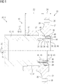
- FIG 1 two combined half-sections of a first embodiment of the claimed flange assembly 10 are shown.
- the flange arrangement 10 comprises a power shaft 12 which interacts with a flange hub 20 and is rotatable about an axis of rotation 15.
- the flange arrangement 10 is shown in a dismantling position 45 above the axis of rotation 15 and in a holding position 43 below the axis of rotation 15.
- the power shaft 12 which can be designed as a drive shaft or output shaft of a gear 50 or electric motor 51 (not shown in detail), is designed as a hollow shaft 13.
- the power shaft 12 is provided with short teeth 17 which mesh with the corresponding short teeth 27 on a cylinder section 22 of the flange hub 20.
- a drive power 25 is transmitted from the power shaft 12 to the flange hub 20 through the meshing short teeth 17, 27.
- the gearing play makes it easier for the flange hub 20 to be pushed onto the power shaft 12.
- the flange hub 20 has a support shoulder 33 on a circumferential inner surface 49, which is also designed circumferentially.
- the flange arrangement 10 also comprises a locking means 30, which is designed essentially as a retaining ring, that is to say comprises a ring section 32.
- Support segments 38 are formed on the locking means 30, between each of which a clear area 39 is formed.
- the support segments 38 of the locking means 30 are designed to exert a holding force 41 on the support shoulder 33 in an assembled state, that is to say in a holding position 43, for axial support 46.
- the support segments 38 belong to one in FIG 1 End face 34 of locking means 30, shown with a broken line, which faces power shaft 12.
- Fastening means 44 which are designed as screws, are received in the locking means 30.
- the fastening means 44 interact with the power shaft 12 and thus exert the holding force 41.
- the holding force 41 is essentially exerted over an area, as a result of which statically overdetermined bearings are avoided.
- the cylinder section 22 is followed by the flange section 24 of the flange hub 20, on which a flange surface 21 is formed, in which flange bores 26 are in turn formed.
- the flange hub 20 can be connected in a torque-transmitting manner to a machine 55 (not shown in detail) via the flange bores 26.
- the support segments 28 of the flange hub 20 belong to an in FIG 1
- the locking means 30 can be rotated about the axis of rotation 15 in such a way that the support segments 28, 38 of the flange hub 20 and the power shaft 12 are opposite one another. In this case there is a dismantling position 45 for the locking means 30.
- a fastening means 44 which is designed as a screw and is received in the locking means 30, a supporting force 31 can be exerted on the power shaft 12, by means of which the locking means 30 is pressed in the direction of the end face 36 facing away from the power shaft 12.
- a dismantling force 42 is exerted on the flange hub 20 by the opposing support segments 28, 38 on the locking means 30 and the flange hub 20. As a result of the dismantling force 42, the flange hub 20 is pulled off.
- the locking means 30 consequently combines two functions, namely as a holding means in the assembled state and as a dismantling aid for the flange arrangement 10.
- FIG 2 shows schematically a second embodiment of the claimed flange arrangement 10 in a longitudinal section.
- the flange arrangement 10 comprises a power shaft 12 which belongs to a gear 50 or electric motor 51 (not shown in detail).
- a flange hub 20 is arranged on the power shaft 12, which is designed as a hollow shaft 13 and can be rotated about an axis of rotation 15.
- the flange hub 20 On a cylinder section 22, the flange hub 20 has a short toothing 27 which engages in a short toothing 17 on the power shaft 17 and thus transmits a drive power 25.
- a rotation takes place in a circumferential direction 47.
- the short teeth 17, 27 there is play between the flange hub 20 and the power shaft 12 in the circumferential direction 47.
- a flange section 24 adjoins the cylinder section 22, in which a flange surface 21 with a plurality of flange bores 26 is formed.
- the drive power 25 can be transmitted to a machine 55 (not shown in detail) through the flange section 21.
- the flange hub 20 is also provided with a centering seat 23 through which the flange hub 20 is aligned on the power shaft 12.
- a circumferential support shoulder 33 which is supported against the power shaft 12, is formed on an inner side 49 of the flange hub 20.
- the flange arrangement 10 also has a locking means 30, which is designed essentially as a retaining ring, that is to say comprises a ring section 32.
- a locking means 30 which are designed as screws, are added, through which the locking means 30 exerts a holding force 41 on the support shoulder 33.
- the flange hub 20 is axially pressed against the power shaft 12.
- radially outwardly projecting support segments 38 of the locking means 38 lie essentially flat on the power shaft 12, thereby avoiding a statically overdetermined bearing.
- the locking means 30 is rotatable about the axis of rotation 15 when the fastening means 44 are released.
- the support segments 38 of the locking means 30 can be positioned opposite the support segments 28 of the flange hub 20, as in FIG FIG 2 shown to be rotated.
- a dismantling force 42 can be exerted on the flange hub 20 by the locking means 30, so there is a dismantling position 45.
- the locking means 30 can be rotated into a holding position 43 in which the support segments 38 of the locking means 30 lie opposite clear areas 29 between support segments 28 of the flange hub 20 and vice versa. In such a holding position 43, the locking means 30 can be mounted and is also suitable for exerting a holding force 41 on the support shoulder 33.
- FIG 3 a flange hub 20 shown, which in a flange assembly 10, for example, according to FIG 1 or FIG 2 can be used.
- the flange hub 20 has a cylinder section 22 and an adjoining flange section 24 with a flange surface 21 and flange bores 26 formed therein.
- a circumferential support shoulder 33 is formed on the inside 49 of the flange hub 20, via which a holding force 41 can be exerted on the flange hub 20.
- radially inwardly projecting support segments 28 are formed, which are essentially ring segment-shaped.
- the support segments 28 are spaced apart from one another by clear areas 29.
- the support segments 38 are suitable for absorbing a dismantling force 42, by means of which a removal of the flange hub 20 from the power shaft 12, not shown in detail, is possible or at least supported.
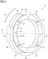
- a locking means 30, which in the embodiments according to FIG 1 and FIG 2 can be used is in FIG 4 shown in an oblique view.
- the locking means 30 is in combination with a flange hub 20 according to FIG 3 applicable.
- the locking means 30 is designed as a retaining ring and comprises a ring section 32.
- Supporting segments 38 are formed on the ring section 32 at a substantially uniform angular spacing.
- the support segments 38 are designed essentially in the shape of a ring segment and protrude radially outward in relation to an axis of rotation 15.
- the support segments 38 are spaced apart from one another in the circumferential direction 47, with clear areas 39 being formed between the support segments 38.
- the locking means 30 also has two end faces 34, 36.
- one of these end faces 34 faces a power shaft 12 and the opposite end face 36 faces away from the power shaft 12, pointing in the direction of its free end.
- the respective sides of the supporting segments 38 also belong to the corresponding end faces.
- bores for receiving fastening means 44 are formed in the locking means 30.
- bores with movement threads 37 are also formed on the locking means 30.
- FIG 5 an embodiment of a claimed wind turbine 70 is shown.
- the wind power plant 70 has a rotor 63 which is rotatably attached to a nacelle 65.
- the rotor 63 is connected to a rotor shaft 62 which serves as a power shaft 12 and through which a generator 64 is driven via a gear 50, which acts as a machine 55 in the The purpose of the present solution is used.
- the rotor shaft 63, the gear 50 and the generator 64 belong to a drive train 65 of the wind turbine 70, which is accommodated in the nacelle 65.
- the gear 50 is connected in a torque-transmitting manner via a flange hub 20 to the rotor shaft 62, which is to be understood as a power shaft 12.
- the rotor shaft 12 and the corresponding flange hub 20 belong to a flange arrangement 10 according to one of the embodiments illustrated above.
- the transmission 50 is provided with a power shaft 12, which is designed as a solid shaft 18 and through which the torque-transmitting connection to the generator 64 is established.
- the power shaft 12, which leads to the generator 64, is coupled to the generator 64 via a flange hub 20.
- the power shaft 12 and the flange hub 20, which couple the generator 64 to the transmission 50 also belong to a flange arrangement 10 according to one of the embodiments outlined above.
- FIG 6 shows schematically the structure of a claimed industrial application 80, which has a drive unit 82 and an output unit 84, which are connected to one another in a torque-transmitting manner via a gear 50.
- the drive unit 82 is designed to provide a drive power 25 which is necessary for the operation of the output unit 84.
- the drive unit 82 is designed as an electric motor 51 for this purpose.
- the output unit 84 is designed as a mechanical application.
- the output unit 84 is designed so that the industrial application 80 is, for example, a mill, vertical mill, sugar mill, cement mill, rock crusher, conveyor belt, pump, roller press, apron conveyor, tube mill, rotary kiln, rotary mechanism, agitator, lifting device, garbage compactor or scrap press.
- the transmission 50 is connected to the drive unit 82 via a power shaft 12 and a flange hub 20.
- the power shaft 12 is here an output shaft of the electric motor 51.
- the flange hub 20 and the power shaft 12 belong to a flange arrangement 10 according to one of the embodiments shown above.
- the transmission 50 is with a Provided power shaft 12, via which the drive power 25 is transmitted to the output unit 84.
- the power shaft 12 is coupled to a flange hub 20 which, together with the power shaft 12, belong to a flange arrangement 10 according to one of the embodiments described above.
- the industrial application 80 is after FIG 6 provided with a flange arrangement 10 which is arranged on an output side of the transmission 50.
- the power shaft 12, which connects the transmission 50 to the output unit 84 is connected to the transmission 50.
Priority Applications (5)
| Application Number | Priority Date | Filing Date | Title |
|---|---|---|---|
| FIEP19195930.3T FI3789625T3 (fi) | 2019-09-06 | 2019-09-06 | Laippajärjestely, vaihteisto, sähkömoottori, tuulivoimala ja teollisuussovellus |
| EP19195930.3A EP3789625B1 (fr) | 2019-09-06 | 2019-09-06 | Agencement de bride, transmission, moteur électrique, éolienne et application industrielle |
| BR102020014402-2A BR102020014402B1 (pt) | 2019-09-06 | 2020-07-15 | Arranjo de flange, cubo flangeado, meio de batente, unidade de engrenagem, motor elétrico, trem de acionamento, turbina eólica, e, aplicação industrial |
| US17/011,701 US11905925B2 (en) | 2019-09-06 | 2020-09-03 | Flange arrangement, flanged hub, stop member, gear unit, electric motor, wind turbine and industrial application |
| CN202010922838.1A CN112460157B (zh) | 2019-09-06 | 2020-09-04 | 法兰设备、法兰毂、锁定件、传动装置和电动机 |
Applications Claiming Priority (1)
| Application Number | Priority Date | Filing Date | Title |
|---|---|---|---|
| EP19195930.3A EP3789625B1 (fr) | 2019-09-06 | 2019-09-06 | Agencement de bride, transmission, moteur électrique, éolienne et application industrielle |
Publications (2)
| Publication Number | Publication Date |
|---|---|
| EP3789625A1 true EP3789625A1 (fr) | 2021-03-10 |
| EP3789625B1 EP3789625B1 (fr) | 2023-01-11 |
Family
ID=67875346
Family Applications (1)
| Application Number | Title | Priority Date | Filing Date |
|---|---|---|---|
| EP19195930.3A Active EP3789625B1 (fr) | 2019-09-06 | 2019-09-06 | Agencement de bride, transmission, moteur électrique, éolienne et application industrielle |
Country Status (4)
| Country | Link |
|---|---|
| US (1) | US11905925B2 (fr) |
| EP (1) | EP3789625B1 (fr) |
| CN (1) | CN112460157B (fr) |
| FI (1) | FI3789625T3 (fr) |
Families Citing this family (3)
| Publication number | Priority date | Publication date | Assignee | Title |
|---|---|---|---|---|
| EP3789625B1 (fr) * | 2019-09-06 | 2023-01-11 | Flender GmbH | Agencement de bride, transmission, moteur électrique, éolienne et application industrielle |
| JP2023137639A (ja) * | 2022-03-18 | 2023-09-29 | 日軽金アクト株式会社 | 垂直軸風車の支持脚固定構造 |
| JP2023137638A (ja) * | 2022-03-18 | 2023-09-29 | 日軽金アクト株式会社 | 垂直軸風車の翼固定構造 |
Citations (5)
| Publication number | Priority date | Publication date | Assignee | Title |
|---|---|---|---|---|
| US4274755A (en) * | 1978-06-30 | 1981-06-23 | Bbc Brown Boveri & Company Limited | Rigid coupling, especially for turbogenerators |
| AT506645A2 (de) * | 2009-07-16 | 2009-10-15 | Avl List Gmbh | Wellenverbindung |
| DE102009019435A1 (de) * | 2008-05-07 | 2009-11-12 | Neumayer Tekfor Holding Gmbh | Verbindungsanordnung |
| DE102013200911A1 (de) | 2012-02-09 | 2013-08-14 | Schaeffler Technologies AG & Co. KG | Verbindungsflansch für Ausrückvorrichtungen |
| WO2017148481A1 (fr) * | 2016-03-01 | 2017-09-08 | Vestas Wind Systems A/S | Éolienne comprenant un raccord de transmission de couple |
Family Cites Families (9)
| Publication number | Priority date | Publication date | Assignee | Title |
|---|---|---|---|---|
| US2381697A (en) * | 1944-04-27 | 1945-08-07 | Frank B Shepard | Hub structure |
| CH582314A5 (fr) * | 1974-09-14 | 1976-11-30 | Ringfeder Gmbh | |
| DE2734784C2 (de) * | 1977-08-02 | 1979-08-30 | Ralph 4041 Huelchrath Muellenberg | Spannsatz |
| WO2011023158A1 (fr) | 2009-08-24 | 2011-03-03 | Schaeffler Technologies Gmbh & Co. Kg | Système de serrage, et procédé de serrage d'une liaison arbre-moyeu |
| CN202056211U (zh) | 2011-03-25 | 2011-11-30 | 宁波中超机器有限公司 | 立辊轧机中的减速机用输出轴联轴器 |
| DE102013002049B4 (de) | 2013-02-07 | 2020-01-16 | Sew-Eurodrive Gmbh & Co Kg | Sensoranordnung und Verfahren |
| EP3502516A1 (fr) | 2017-12-19 | 2019-06-26 | Flender GmbH | Engrenage planétaire, groupe motopropulseur et éolienne |
| CN209309157U (zh) | 2018-10-12 | 2019-08-27 | 洛阳豪智机械有限公司 | 一种风电主轴锁紧盘的内环大法兰组合式对接装置 |
| EP3789625B1 (fr) * | 2019-09-06 | 2023-01-11 | Flender GmbH | Agencement de bride, transmission, moteur électrique, éolienne et application industrielle |
-
2019
- 2019-09-06 EP EP19195930.3A patent/EP3789625B1/fr active Active
- 2019-09-06 FI FIEP19195930.3T patent/FI3789625T3/fi active
-
2020
- 2020-09-03 US US17/011,701 patent/US11905925B2/en active Active
- 2020-09-04 CN CN202010922838.1A patent/CN112460157B/zh active Active
Patent Citations (5)
| Publication number | Priority date | Publication date | Assignee | Title |
|---|---|---|---|---|
| US4274755A (en) * | 1978-06-30 | 1981-06-23 | Bbc Brown Boveri & Company Limited | Rigid coupling, especially for turbogenerators |
| DE102009019435A1 (de) * | 2008-05-07 | 2009-11-12 | Neumayer Tekfor Holding Gmbh | Verbindungsanordnung |
| AT506645A2 (de) * | 2009-07-16 | 2009-10-15 | Avl List Gmbh | Wellenverbindung |
| DE102013200911A1 (de) | 2012-02-09 | 2013-08-14 | Schaeffler Technologies AG & Co. KG | Verbindungsflansch für Ausrückvorrichtungen |
| WO2017148481A1 (fr) * | 2016-03-01 | 2017-09-08 | Vestas Wind Systems A/S | Éolienne comprenant un raccord de transmission de couple |
Also Published As
| Publication number | Publication date |
|---|---|
| US11905925B2 (en) | 2024-02-20 |
| US20210071646A1 (en) | 2021-03-11 |
| EP3789625B1 (fr) | 2023-01-11 |
| BR102020014402A2 (pt) | 2021-03-23 |
| CN112460157B (zh) | 2023-03-14 |
| FI3789625T3 (fi) | 2023-03-28 |
| CN112460157A (zh) | 2021-03-09 |
Similar Documents
| Publication | Publication Date | Title |
|---|---|---|
| EP1251268B1 (fr) | Dispositif de connexion des arbres d'une éolienne | |
| EP3789625B1 (fr) | Agencement de bride, transmission, moteur électrique, éolienne et application industrielle | |
| EP3587863A1 (fr) | Engrenage planétaire, chaîne cinématique, éolienne et application industrielle | |
| DE2541726C2 (de) | Hauptrotor-Getriebe für einen Hubschrauber | |
| EP3322908B1 (fr) | Mécanisme de transmission comprenant un flasque de butée pour le blocage axial d'éléments roulants d'un palier | |
| EP1757839A1 (fr) | Transmission pour un broyeur à auge | |
| DE102014225136A1 (de) | Getriebeverdichter, Anordnung mit einem Antrieb und einem Getriebeverdichter | |
| WO2014187540A1 (fr) | Liaison arbre-moyeu et électroréducteur | |
| EP3734112A1 (fr) | Train épicycloïdal | |
| DE102011082671A1 (de) | Antriebseinheit für ein Flurförderzeug | |
| EP2511010B1 (fr) | Entraînement de moulin vertical | |
| WO2017008874A1 (fr) | Transmission comprenant au moins un arbre à excentrique | |
| EP2761174B1 (fr) | Transmission d'une éolienne dotée d'un entraînement auxiliaire, éolienne et procédé destiné à amener en rotation un arbre de rotor d'une éolienne | |
| EP4031783B1 (fr) | Série de boîtes de vitesses à trains planétaires, éolienne, application industrielle et utilisation de roulements | |
| EP3599393A1 (fr) | Engrenage couplé pour éoliennes et applications industrielles | |
| EP3491272B1 (fr) | Dispositif d'entrainement comportant une boîte de superposition | |
| EP3139067B1 (fr) | Train epicycloïdal | |
| EP3823893A1 (fr) | Transmission de bateau et système d'entraînement pour une propulsion de bateau | |
| DE102019115283A1 (de) | Ein Differentialgetriebe und ein Fahrzeug mit einem Differentialgetriebe | |
| EP3882490A1 (fr) | Agencement de pignon cylindrique à centrage amélioré | |
| EP4028672B1 (fr) | Système de transmission de couple de rotation avec roulements agencés concentriquement, unité d'entraînement et ensemble d'entraînement | |
| EP3712453B1 (fr) | Accouplement pourvu de raccordement douille-bague amélioré | |
| DE102017214658A1 (de) | Vorrichtung zur lösbaren axialen Verbindung eines Elementes eines Planetengetriebes eines Kraftfahrzeugs mit einer Getriebewelle | |
| DE3526837A1 (de) | Epizykloidengetriebe-uebertragungsanordnung | |
| EP3599391A1 (fr) | Engrenage couplé pour éoliennes et applications industrielles |
Legal Events
| Date | Code | Title | Description |
|---|---|---|---|
| PUAI | Public reference made under article 153(3) epc to a published international application that has entered the european phase |
Free format text: ORIGINAL CODE: 0009012 |
|
| STAA | Information on the status of an ep patent application or granted ep patent |
Free format text: STATUS: THE APPLICATION HAS BEEN PUBLISHED |
|
| AK | Designated contracting states |
Kind code of ref document: A1 Designated state(s): AL AT BE BG CH CY CZ DE DK EE ES FI FR GB GR HR HU IE IS IT LI LT LU LV MC MK MT NL NO PL PT RO RS SE SI SK SM TR |
|
| AX | Request for extension of the european patent |
Extension state: BA ME |
|
| STAA | Information on the status of an ep patent application or granted ep patent |
Free format text: STATUS: REQUEST FOR EXAMINATION WAS MADE |
|
| 17P | Request for examination filed |
Effective date: 20210831 |
|
| RBV | Designated contracting states (corrected) |
Designated state(s): AL AT BE BG CH CY CZ DE DK EE ES FI FR GB GR HR HU IE IS IT LI LT LU LV MC MK MT NL NO PL PT RO RS SE SI SK SM TR |
|
| GRAJ | Information related to disapproval of communication of intention to grant by the applicant or resumption of examination proceedings by the epo deleted |
Free format text: ORIGINAL CODE: EPIDOSDIGR1 |
|
| GRAP | Despatch of communication of intention to grant a patent |
Free format text: ORIGINAL CODE: EPIDOSNIGR1 |
|
| GRAP | Despatch of communication of intention to grant a patent |
Free format text: ORIGINAL CODE: EPIDOSNIGR1 |
|
| STAA | Information on the status of an ep patent application or granted ep patent |
Free format text: STATUS: GRANT OF PATENT IS INTENDED |
|
| INTG | Intention to grant announced |
Effective date: 20221025 |
|
| GRAS | Grant fee paid |
Free format text: ORIGINAL CODE: EPIDOSNIGR3 |
|
| GRAA | (expected) grant |
Free format text: ORIGINAL CODE: 0009210 |
|
| STAA | Information on the status of an ep patent application or granted ep patent |
Free format text: STATUS: THE PATENT HAS BEEN GRANTED |
|
| AK | Designated contracting states |
Kind code of ref document: B1 Designated state(s): AL AT BE BG CH CY CZ DE DK EE ES FI FR GB GR HR HU IE IS IT LI LT LU LV MC MK MT NL NO PL PT RO RS SE SI SK SM TR |
|
| REG | Reference to a national code |
Ref country code: GB Ref legal event code: FG4D Free format text: NOT ENGLISH |
|
| REG | Reference to a national code |
Ref country code: CH Ref legal event code: EP |
|
| REG | Reference to a national code |
Ref country code: DE Ref legal event code: R096 Ref document number: 502019006752 Country of ref document: DE |
|
| REG | Reference to a national code |
Ref country code: IE Ref legal event code: FG4D Free format text: LANGUAGE OF EP DOCUMENT: GERMAN |
|
| REG | Reference to a national code |
Ref country code: AT Ref legal event code: REF Ref document number: 1543599 Country of ref document: AT Kind code of ref document: T Effective date: 20230215 |
|
| REG | Reference to a national code |
Ref country code: LT Ref legal event code: MG9D |
|
| REG | Reference to a national code |
Ref country code: NL Ref legal event code: MP Effective date: 20230111 |
|
| PG25 | Lapsed in a contracting state [announced via postgrant information from national office to epo] |
Ref country code: NL Free format text: LAPSE BECAUSE OF FAILURE TO SUBMIT A TRANSLATION OF THE DESCRIPTION OR TO PAY THE FEE WITHIN THE PRESCRIBED TIME-LIMIT Effective date: 20230111 |
|
| PG25 | Lapsed in a contracting state [announced via postgrant information from national office to epo] |
Ref country code: RS Free format text: LAPSE BECAUSE OF FAILURE TO SUBMIT A TRANSLATION OF THE DESCRIPTION OR TO PAY THE FEE WITHIN THE PRESCRIBED TIME-LIMIT Effective date: 20230111 Ref country code: PT Free format text: LAPSE BECAUSE OF FAILURE TO SUBMIT A TRANSLATION OF THE DESCRIPTION OR TO PAY THE FEE WITHIN THE PRESCRIBED TIME-LIMIT Effective date: 20230511 Ref country code: NO Free format text: LAPSE BECAUSE OF FAILURE TO SUBMIT A TRANSLATION OF THE DESCRIPTION OR TO PAY THE FEE WITHIN THE PRESCRIBED TIME-LIMIT Effective date: 20230411 Ref country code: LV Free format text: LAPSE BECAUSE OF FAILURE TO SUBMIT A TRANSLATION OF THE DESCRIPTION OR TO PAY THE FEE WITHIN THE PRESCRIBED TIME-LIMIT Effective date: 20230111 Ref country code: LT Free format text: LAPSE BECAUSE OF FAILURE TO SUBMIT A TRANSLATION OF THE DESCRIPTION OR TO PAY THE FEE WITHIN THE PRESCRIBED TIME-LIMIT Effective date: 20230111 Ref country code: HR Free format text: LAPSE BECAUSE OF FAILURE TO SUBMIT A TRANSLATION OF THE DESCRIPTION OR TO PAY THE FEE WITHIN THE PRESCRIBED TIME-LIMIT Effective date: 20230111 Ref country code: ES Free format text: LAPSE BECAUSE OF FAILURE TO SUBMIT A TRANSLATION OF THE DESCRIPTION OR TO PAY THE FEE WITHIN THE PRESCRIBED TIME-LIMIT Effective date: 20230111 |
|
| PG25 | Lapsed in a contracting state [announced via postgrant information from national office to epo] |
Ref country code: SE Free format text: LAPSE BECAUSE OF FAILURE TO SUBMIT A TRANSLATION OF THE DESCRIPTION OR TO PAY THE FEE WITHIN THE PRESCRIBED TIME-LIMIT Effective date: 20230111 Ref country code: PL Free format text: LAPSE BECAUSE OF FAILURE TO SUBMIT A TRANSLATION OF THE DESCRIPTION OR TO PAY THE FEE WITHIN THE PRESCRIBED TIME-LIMIT Effective date: 20230111 Ref country code: IS Free format text: LAPSE BECAUSE OF FAILURE TO SUBMIT A TRANSLATION OF THE DESCRIPTION OR TO PAY THE FEE WITHIN THE PRESCRIBED TIME-LIMIT Effective date: 20230511 Ref country code: GR Free format text: LAPSE BECAUSE OF FAILURE TO SUBMIT A TRANSLATION OF THE DESCRIPTION OR TO PAY THE FEE WITHIN THE PRESCRIBED TIME-LIMIT Effective date: 20230412 |
|
| REG | Reference to a national code |
Ref country code: DE Ref legal event code: R097 Ref document number: 502019006752 Country of ref document: DE |
|
| PG25 | Lapsed in a contracting state [announced via postgrant information from national office to epo] |
Ref country code: SM Free format text: LAPSE BECAUSE OF FAILURE TO SUBMIT A TRANSLATION OF THE DESCRIPTION OR TO PAY THE FEE WITHIN THE PRESCRIBED TIME-LIMIT Effective date: 20230111 Ref country code: RO Free format text: LAPSE BECAUSE OF FAILURE TO SUBMIT A TRANSLATION OF THE DESCRIPTION OR TO PAY THE FEE WITHIN THE PRESCRIBED TIME-LIMIT Effective date: 20230111 Ref country code: EE Free format text: LAPSE BECAUSE OF FAILURE TO SUBMIT A TRANSLATION OF THE DESCRIPTION OR TO PAY THE FEE WITHIN THE PRESCRIBED TIME-LIMIT Effective date: 20230111 Ref country code: DK Free format text: LAPSE BECAUSE OF FAILURE TO SUBMIT A TRANSLATION OF THE DESCRIPTION OR TO PAY THE FEE WITHIN THE PRESCRIBED TIME-LIMIT Effective date: 20230111 Ref country code: CZ Free format text: LAPSE BECAUSE OF FAILURE TO SUBMIT A TRANSLATION OF THE DESCRIPTION OR TO PAY THE FEE WITHIN THE PRESCRIBED TIME-LIMIT Effective date: 20230111 |
|
| PGFP | Annual fee paid to national office [announced via postgrant information from national office to epo] |
Ref country code: TR Payment date: 20230905 Year of fee payment: 5 Ref country code: FI Payment date: 20230920 Year of fee payment: 5 |
|
| PLBE | No opposition filed within time limit |
Free format text: ORIGINAL CODE: 0009261 |
|
| STAA | Information on the status of an ep patent application or granted ep patent |
Free format text: STATUS: NO OPPOSITION FILED WITHIN TIME LIMIT |
|
| PG25 | Lapsed in a contracting state [announced via postgrant information from national office to epo] |
Ref country code: SK Free format text: LAPSE BECAUSE OF FAILURE TO SUBMIT A TRANSLATION OF THE DESCRIPTION OR TO PAY THE FEE WITHIN THE PRESCRIBED TIME-LIMIT Effective date: 20230111 |
|
| PGFP | Annual fee paid to national office [announced via postgrant information from national office to epo] |
Ref country code: FR Payment date: 20230928 Year of fee payment: 5 Ref country code: DE Payment date: 20230920 Year of fee payment: 5 Ref country code: BE Payment date: 20230920 Year of fee payment: 5 |
|
| 26N | No opposition filed |
Effective date: 20231012 |
|
| PG25 | Lapsed in a contracting state [announced via postgrant information from national office to epo] |
Ref country code: SI Free format text: LAPSE BECAUSE OF FAILURE TO SUBMIT A TRANSLATION OF THE DESCRIPTION OR TO PAY THE FEE WITHIN THE PRESCRIBED TIME-LIMIT Effective date: 20230111 |
|
| REG | Reference to a national code |
Ref country code: CH Ref legal event code: PL |