EP3789231A1 - Freinage par récupération électrique efficace - Google Patents
Freinage par récupération électrique efficace Download PDFInfo
- Publication number
- EP3789231A1 EP3789231A1 EP20189441.7A EP20189441A EP3789231A1 EP 3789231 A1 EP3789231 A1 EP 3789231A1 EP 20189441 A EP20189441 A EP 20189441A EP 3789231 A1 EP3789231 A1 EP 3789231A1
- Authority
- EP
- European Patent Office
- Prior art keywords
- switch
- braking
- mode
- brake
- resonance
- Prior art date
- Legal status (The legal status is an assumption and is not a legal conclusion. Google has not performed a legal analysis and makes no representation as to the accuracy of the status listed.)
- Granted
Links
- 230000001172 regenerating effect Effects 0.000 title claims abstract description 52
- 238000000034 method Methods 0.000 claims abstract description 30
- 230000008929 regeneration Effects 0.000 claims abstract description 19
- 238000011069 regeneration method Methods 0.000 claims abstract description 19
- 230000008878 coupling Effects 0.000 claims description 2
- 238000010168 coupling process Methods 0.000 claims description 2
- 238000005859 coupling reaction Methods 0.000 claims description 2
- 230000008901 benefit Effects 0.000 description 4
- 239000003990 capacitor Substances 0.000 description 4
- 230000000694 effects Effects 0.000 description 3
- 238000004146 energy storage Methods 0.000 description 3
- 230000009471 action Effects 0.000 description 2
- 238000007796 conventional method Methods 0.000 description 2
- 230000008569 process Effects 0.000 description 2
- 230000004044 response Effects 0.000 description 2
- 238000004804 winding Methods 0.000 description 2
- 230000001133 acceleration Effects 0.000 description 1
- 230000004075 alteration Effects 0.000 description 1
- 230000015556 catabolic process Effects 0.000 description 1
- 238000001514 detection method Methods 0.000 description 1
- 230000001627 detrimental effect Effects 0.000 description 1
- 239000000446 fuel Substances 0.000 description 1
- 238000012423 maintenance Methods 0.000 description 1
- 238000010248 power generation Methods 0.000 description 1
- 230000004043 responsiveness Effects 0.000 description 1
- 238000006467 substitution reaction Methods 0.000 description 1
- 230000001131 transforming effect Effects 0.000 description 1
Images


Classifications
-
- B—PERFORMING OPERATIONS; TRANSPORTING
- B60—VEHICLES IN GENERAL
- B60L—PROPULSION OF ELECTRICALLY-PROPELLED VEHICLES; SUPPLYING ELECTRIC POWER FOR AUXILIARY EQUIPMENT OF ELECTRICALLY-PROPELLED VEHICLES; ELECTRODYNAMIC BRAKE SYSTEMS FOR VEHICLES IN GENERAL; MAGNETIC SUSPENSION OR LEVITATION FOR VEHICLES; MONITORING OPERATING VARIABLES OF ELECTRICALLY-PROPELLED VEHICLES; ELECTRIC SAFETY DEVICES FOR ELECTRICALLY-PROPELLED VEHICLES
- B60L7/00—Electrodynamic brake systems for vehicles in general
- B60L7/10—Dynamic electric regenerative braking
- B60L7/12—Dynamic electric regenerative braking for vehicles propelled by dc motors
-
- B—PERFORMING OPERATIONS; TRANSPORTING
- B60—VEHICLES IN GENERAL
- B60L—PROPULSION OF ELECTRICALLY-PROPELLED VEHICLES; SUPPLYING ELECTRIC POWER FOR AUXILIARY EQUIPMENT OF ELECTRICALLY-PROPELLED VEHICLES; ELECTRODYNAMIC BRAKE SYSTEMS FOR VEHICLES IN GENERAL; MAGNETIC SUSPENSION OR LEVITATION FOR VEHICLES; MONITORING OPERATING VARIABLES OF ELECTRICALLY-PROPELLED VEHICLES; ELECTRIC SAFETY DEVICES FOR ELECTRICALLY-PROPELLED VEHICLES
- B60L1/00—Supplying electric power to auxiliary equipment of vehicles
- B60L1/003—Supplying electric power to auxiliary equipment of vehicles to auxiliary motors, e.g. for pumps, compressors
-
- B—PERFORMING OPERATIONS; TRANSPORTING
- B60—VEHICLES IN GENERAL
- B60L—PROPULSION OF ELECTRICALLY-PROPELLED VEHICLES; SUPPLYING ELECTRIC POWER FOR AUXILIARY EQUIPMENT OF ELECTRICALLY-PROPELLED VEHICLES; ELECTRODYNAMIC BRAKE SYSTEMS FOR VEHICLES IN GENERAL; MAGNETIC SUSPENSION OR LEVITATION FOR VEHICLES; MONITORING OPERATING VARIABLES OF ELECTRICALLY-PROPELLED VEHICLES; ELECTRIC SAFETY DEVICES FOR ELECTRICALLY-PROPELLED VEHICLES
- B60L3/00—Electric devices on electrically-propelled vehicles for safety purposes; Monitoring operating variables, e.g. speed, deceleration or energy consumption
- B60L3/0023—Detecting, eliminating, remedying or compensating for drive train abnormalities, e.g. failures within the drive train
- B60L3/0061—Detecting, eliminating, remedying or compensating for drive train abnormalities, e.g. failures within the drive train relating to electrical machines
-
- B—PERFORMING OPERATIONS; TRANSPORTING
- B60—VEHICLES IN GENERAL
- B60L—PROPULSION OF ELECTRICALLY-PROPELLED VEHICLES; SUPPLYING ELECTRIC POWER FOR AUXILIARY EQUIPMENT OF ELECTRICALLY-PROPELLED VEHICLES; ELECTRODYNAMIC BRAKE SYSTEMS FOR VEHICLES IN GENERAL; MAGNETIC SUSPENSION OR LEVITATION FOR VEHICLES; MONITORING OPERATING VARIABLES OF ELECTRICALLY-PROPELLED VEHICLES; ELECTRIC SAFETY DEVICES FOR ELECTRICALLY-PROPELLED VEHICLES
- B60L3/00—Electric devices on electrically-propelled vehicles for safety purposes; Monitoring operating variables, e.g. speed, deceleration or energy consumption
- B60L3/0023—Detecting, eliminating, remedying or compensating for drive train abnormalities, e.g. failures within the drive train
- B60L3/0076—Detecting, eliminating, remedying or compensating for drive train abnormalities, e.g. failures within the drive train relating to braking
-
- B—PERFORMING OPERATIONS; TRANSPORTING
- B60—VEHICLES IN GENERAL
- B60L—PROPULSION OF ELECTRICALLY-PROPELLED VEHICLES; SUPPLYING ELECTRIC POWER FOR AUXILIARY EQUIPMENT OF ELECTRICALLY-PROPELLED VEHICLES; ELECTRODYNAMIC BRAKE SYSTEMS FOR VEHICLES IN GENERAL; MAGNETIC SUSPENSION OR LEVITATION FOR VEHICLES; MONITORING OPERATING VARIABLES OF ELECTRICALLY-PROPELLED VEHICLES; ELECTRIC SAFETY DEVICES FOR ELECTRICALLY-PROPELLED VEHICLES
- B60L7/00—Electrodynamic brake systems for vehicles in general
- B60L7/003—Dynamic electric braking by short circuiting the motor
-
- B—PERFORMING OPERATIONS; TRANSPORTING
- B60—VEHICLES IN GENERAL
- B60L—PROPULSION OF ELECTRICALLY-PROPELLED VEHICLES; SUPPLYING ELECTRIC POWER FOR AUXILIARY EQUIPMENT OF ELECTRICALLY-PROPELLED VEHICLES; ELECTRODYNAMIC BRAKE SYSTEMS FOR VEHICLES IN GENERAL; MAGNETIC SUSPENSION OR LEVITATION FOR VEHICLES; MONITORING OPERATING VARIABLES OF ELECTRICALLY-PROPELLED VEHICLES; ELECTRIC SAFETY DEVICES FOR ELECTRICALLY-PROPELLED VEHICLES
- B60L7/00—Electrodynamic brake systems for vehicles in general
- B60L7/10—Dynamic electric regenerative braking
- B60L7/18—Controlling the braking effect
-
- B—PERFORMING OPERATIONS; TRANSPORTING
- B60—VEHICLES IN GENERAL
- B60L—PROPULSION OF ELECTRICALLY-PROPELLED VEHICLES; SUPPLYING ELECTRIC POWER FOR AUXILIARY EQUIPMENT OF ELECTRICALLY-PROPELLED VEHICLES; ELECTRODYNAMIC BRAKE SYSTEMS FOR VEHICLES IN GENERAL; MAGNETIC SUSPENSION OR LEVITATION FOR VEHICLES; MONITORING OPERATING VARIABLES OF ELECTRICALLY-PROPELLED VEHICLES; ELECTRIC SAFETY DEVICES FOR ELECTRICALLY-PROPELLED VEHICLES
- B60L7/00—Electrodynamic brake systems for vehicles in general
- B60L7/22—Dynamic electric resistor braking, combined with dynamic electric regenerative braking
-
- B—PERFORMING OPERATIONS; TRANSPORTING
- B60—VEHICLES IN GENERAL
- B60L—PROPULSION OF ELECTRICALLY-PROPELLED VEHICLES; SUPPLYING ELECTRIC POWER FOR AUXILIARY EQUIPMENT OF ELECTRICALLY-PROPELLED VEHICLES; ELECTRODYNAMIC BRAKE SYSTEMS FOR VEHICLES IN GENERAL; MAGNETIC SUSPENSION OR LEVITATION FOR VEHICLES; MONITORING OPERATING VARIABLES OF ELECTRICALLY-PROPELLED VEHICLES; ELECTRIC SAFETY DEVICES FOR ELECTRICALLY-PROPELLED VEHICLES
- B60L2220/00—Electrical machine types; Structures or applications thereof
- B60L2220/10—Electrical machine types
- B60L2220/20—DC electrical machines
Definitions
- the present invention generally relates to electrical systems, and more specifically to a system and method for operating an efficient regenerative resonance electrical braking system.
- the principal of regenerative braking is utilized to capture, like electrical energy, much of the energy otherwise lost to heat during braking.
- the kinetic energy converted to electrical energy during regenerative braking is utilized to charge, or recharge, a suitable device in an electrical energy storage system.
- that electrical energy storage system is then able to supply a portion of the electrical energy required to power the traction motor(s) during periods of vehicle acceleration and/or maintenance of constant velocity.
- a method for operating the braking includes operating an electrical braking system in at least one mode; sensing a condition of the electrical braking system; and performing braking based at least in part on the at least one mode and the sensed condition.
- further embodiments include operating the electrical braking system in a pulsed mode, wherein when in the pulsed mode a switch that is parallel with a brake resistor is switched OFF; and controlling a first brake drive switch based on a configurable duty cycle.
- further embodiments include operating the electrical braking system in a resonance regenerative mode, wherein when in the resonance regenerative mode a switch that is parallel to the brake resistor is switched ON; and controlling a first brake drive switch and a second brake drive switch in a sequential fashion which allows current to flow to a transformer for regeneration.
- further embodiments include storing the energy during the resonance regenerative mode.
- further embodiments include providing energy to an auxiliary system.
- further embodiments include operating the electrical brake system in a combination pulsed braking and resonance regenerative mode; switching a switch that is parallel to the brake resistor OFF; and switching a first brake drive switch according to a configurable duty cycle to allow for pulsed braking and resonance regeneration.
- further embodiments include using a sensed condition, wherein the sensed condition is a DC link voltage.
- further embodiments include using a sensed condition, wherein the sensed condition exceeds a DC link upper threshold voltage.
- further embodiments include implementing switching that is controlled by pulse width modulation (PWM) signal.
- PWM pulse width modulation
- further embodiments include coupling a transform to each phase of a motor; and performing braking for each phase based at least in part on the at least one mode and the sensed condition.
- a system for for performing efficient regenerative resonance electrical braking.
- the system includes a controller; a motor coupled to an H-bridge network; a DC link coupled to the motor; and an electrical braking system electrically coupled to the motor.
- the electrical braking system includes a sense circuit configured to sense a condition of the DC link; a brake resistor coupled to the DC link; a drive circuit coupled to the sense circuit; and a transformer for regeneration.
- further embodiments include an electrical braking system that is configured to operate in a pulsed mode, wherein when in the pulsed mode a switch that is parallel with the brake resistor is switched OFF, and is configured to control a first brake drive switch based on a configurable duty cycle.
- further embodiments include the electrical braking system is configured to operate in a resonance regenerative mode, wherein when in the resonance regenerative mode a switch that is parallel to the brake resistor is switched ON, and is configured to control a first brake drive switch and a second brake drive switch in a sequential fashion which allows current to flow to the transformer for regeneration.
- further embodiments include an electrical braking system that is configured to operate in a combination pulsed braking and resonance regenerative mode, switch a switch parallel to the brake resistor OFF, and switch a first brake drive switch according to a configurable duty cycle to allow for pulsed braking and resonance regeneration.
- further embodiments include using a sensed condition, wherein the sensed condition is a DC link voltage.
- further embodiments include using a sensed condition, wherein the sensed condition exceeds a DC link upper threshold voltage.
- further embodiments include a controller that is configured to provide control signals including pulse width modulation (PWM) signal.
- PWM pulse width modulation
- further embodiments include a sense circuit that includes a Zener diode configuration.
- further embodiments include an electrical braking system that is configured in a star connected configuration.
- further embodiments include a star connected configuration where a transformer is coupled to each phase of the motor, wherein each transformer performs braking for each phase based at least in part on at least one of a mode and the sensed condition.
- a motor driving apparatus includes a DC link capacitor, H-bridge switches configuration for driving the motor, PWM circuit for each IGBT drive, brake drive, and transformer for regeneration.
- a switchable configuration short form of connection to generate electrical braking by deploying a brake resistor and LC network to the motor coil.
- the braking of a motor in an electric drive is typically accomplished by closing brake contacts across the motor windings after the trigger of the switch that couples power to the motor windings is opened.
- This conventional technique results in very high currents during braking with increased size of brake resistors and power dissipated as heat with no regeneration. Further, it results in sudden braking, which can be detrimental to the life of the motor system.
- the techniques described herein are capable of minimizing the size of the brake resistor and power dissipation in the brake resistor during the braking operation.
- the responsiveness, power generation, and control performance is improved by executing the braking operations using pulse braking mode and resonance regenerative braking mode.
- the braking circuit is fed with back EMF generated by the motor when power is disconnected from the motor.
- the regenerative power must be dissipated in the drive itself to avoid instability problem in the aircraft power supply.
- the regenerative braking system drives a motor by using the kinetic energy and charges a battery/DC link capacitor with electric energy generated from the motor in order to improve the efficiency of the electric drive, so that the regenerative braking system improves the fuel consumption ratio.
- an active-control braking device capable of reducing braking force corresponding to the regenerative braking torque is necessary.
- the brake resistor when operating in the pulse braking mode, is turned ON for a longer duration when compared to operating in the regenerative mode.
- the duty cycle for one or more switching transistors is configured to allow for faster braking. Therefore, the brake resistor will engage motor brake fast enough to stop the mechanical movement.
- the duty cycle can be configured according to the desired braking method. The pulse braking method aids in stopping further rotor movement.
- the switching transistors are turned ON in a sequential fashion.
- This mode provides regenerative power from the excess back EMF generated above the DC LINK upper threshold voltage.
- This energy can be utilized for driving auxiliary loads in the system.
- the energy can be stored in an energy storage device such as a battery.
- the techniques described herein also provide for operating the electrical braking system in a combined mode including the resonance regenerative braking and pulse braking mode.
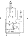
- FIG. 1 depicts a circuit for resonance electrical braking system 100 in accordance with one or more embodiments.
- FIG. 1 depicts a motor and an H-bridge circuit including switches Q1, Q2, Q3, Q4, Q5, Q6, and diodes D1, D2, D3, D4, D5, D6.
- the motor is a brushless DC motor. In other embodiments a brushed motor can be used. It should be understood the techniques described herein can also be applied to alternating current (AC) motors as well.
- the diodes D1-D6 are connected across the corresponding switches Q1-Q6.
- the H-bridge circuit is coupled to a switching logic (not shown) to control the output of the H-bridge circuit.
- FIG. 1 depicts a circuit for resonance electrical braking system 100 in accordance with one or more embodiments.
- FIG. 1 depicts a motor and an H-bridge circuit including switches Q1, Q2, Q3, Q4, Q5, Q6, and diodes D1, D2, D3, D4, D5, D6.
- the motor is
- FIG. 1 depicts a comparator A1, logic devices (OR gates) A3, A4, a brake resistor B_Res connected in parallel with the switch Q9 and the diode D9. Also shown in FIG. 1 are brake switches Q7, Q8 with corresponding diodes D12, D11 arranged across the brake switches Q7, Q8. The brake switches Q7, Q8 are controlled by the brake drives 110, 120.
- the transformer T1 is coupled across the brake switch Q7 and is configured to perform the regeneration process during braking.
- the DC link can hold-up to 270 Vdc to operate the load drive.
- the back EMF generated by the motor charges the DC link capacitor to the upper threshold voltage.
- the upper threshold is 380 V. It should be understood the upper threshold can be selected based on a particular application.
- the brake resistor B_Res is turned ON to dissipate the excess energy as heat. That is, the switch Q9 is switch OFF to allow the brake resistor to dissipate the excess energy.
- the upper voltage threshold sense circuit includes a series of thick film resistors R1, R2, R3, R4 that provide the sensed DC link voltage to the non-inverting terminal of the comparator A1.
- the inverting terminal of the comparator A1 is provided with a reference voltage (Vref) which is used to compare the sensed voltage to determine whether an upper threshold has been exceeded.
- Logic devices A3, A4 (OR gates) are coupled to the comparator and receive input from the comparator A1 and switching logic (not shown). The output of the logic devices A3, A4 are provided to the brake drives 110, 120 to control the switches Q7, Q8, respectively. In one embodiment, the logic devices A3, A4 trigger the brake drives 110, 120 when it receives logic HIGH signal. It is to be noted that the comparator A1 will overdrive the brake drives 110, 120 if the DC link voltage reaches the upper threshold value during back EMF generation and comparator A1 is implemented for the DC link protection function.
- the brake resistor B_Res When the system 100 operates in the pulse braking mode, the brake resistor B_Res is turned ON for a longer duration when compared to the regenerative mode.
- the duty cycle for the switch Q7 is configured with a ton (switch/transistor ON duty cycle) > 50%, switch Q8 is ON and switch Q9 is in the OFF state. Therefore, the brake resistor (B_Res) will engage the motor brake fast enough to stop the mechanical movement.
- the pulse braking method aids in stopping the rotor movement of the braking system.
- the regeneration voltage is considerably less than when operating in the resonance regenerative braking mode described below.
- the operation can be carried out with the resonance regenerative braking by turning ON switches Q8 and Q7 sequentially. That is, switches Q8, Q7 are switched 180 degrees out of phase ( ton and toff duty cycle can be varied for the desired braking response).
- the switch Q9 is turned ON to provide lossless power in the brake resistor B_Res for efficient regenerative braking.
- the brake resistor B_Res is in series with LC which limits the amount of current flowing to the LC circuit of the transformer T1.
- the LC series resonance of the transformer T1 is limited to the maximum current capability and in such case the resistive braking is deployed sequentially to the LC circuit for efficient braking within a short duration.
- the brake resistor B_Res is in series with LC circuit of the transformer T1 which limits the amount of current flow in the LC circuit.
- the pulse braking mode is activated and during the toff cycle the brake energy will flow through the LC network (L1, C2) of the transformer T1.
- the resonance regenerative braking mode will engage the motor brake dynamically (i.e., resonance regenerative braking and resistive pulse braking) to stop the mechanical movement. This action provides regenerative power from the excess back EMF generated above the DC link upper threshold voltage. This energy can be utilized for driving auxiliary load in the system or stored in a storage device for future use.
- FIG. 2 an alternative arrangement for an electrical braking system 200 in accordance with one or more embodiments is shown.
- the system 200 includes similar components as that shown in FIG. 1 including the motor, H-bridge circuit having switches Q1-Q6 and diodes D1-D6, the DC link, brake resistor B Res, switch Q9, brake drives 110, 120 and switches Q7, Q8, and transformer T1.
- the system 200 includes the resistors R1, R2, R3, R4 which provide a bias to switch Q10 (e.g., PNP transistor) and the Zener diodes D11, D13, D15 are configured to turn ON once the back EMF voltage goes above an upper threshold, i.e., 380 V.
- the resistor R1 limits the current for Zener diode conduction.
- the switch Q8 will turn ON once Zener breakdown occurs, and the voltage across the resistor R2 provides a logic HIGH to logic devices A1, A2.
- the diode D16 protects the logic devices A1, A2 from over-voltage during operation. It should be understood that the system 200 can operate in the modes including the pulsed braking mode, the resonance regenerative mode, and the combination mode as described with reference to FIG. 1 .
- FIG. 3 depicts another arrangement for an electrical braking system 300 in accordance with one or more embodiments.
- the system 300 includes similar components as that shown in FIG. 1 including the motor, H-bridge circuit having switches Q1-Q6 and diodes D1-D6, the DC link, brake resistor B_Res, switch Q9, brake drive 110 and switch Q7, and transformer T1.
- the upper voltage threshold sense circuit includes a series of resistors R1, R2, R3, R4 and provides the DC link voltage sense signal to the non-inverting terminal of the comparator A1 for the brake drive 110.
- the logic device A2 will trigger the brake drive 110 when it receives a logic HIGH signal.
- the comparator A1 will overdrive the brake drive 110 in the event the DC link voltage reaches the worst case value during the back EMF generation.
- the comparator A1 is implemented for the DC link protection function.
- the system 200 can operate in the modes including the pulsed braking mode, the resonance regenerative braking mode, and the combination mode as described with reference to FIG. 1 .
- the pulsed braking mode the switch Q8 is switched OFF allowing the current to flow through brake resistor B_Res and the braking is controlled by the duty cycle ton for Q7 is set to ton > 50%.
- the switch Q8 is switched OFF and the duty cycle ton for switch Q7 can be set to allow for a sufficient amount of current to flow to the transformer to perform regeneration.
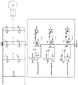
- FIG. 4 depicts an arrangement for an electrical braking system 400 with a star connected brake drive in accordance with one or more embodiments.
- the system 400 includes a motor, DC link, and an H-bridge circuit having switches Q1-Q6 and diodes D1-D6.
- the system 400 also includes brake drive switches Q7, Q8, Q9, brake resistors B_Res, B_Res1, B_Res2, and transformers T1, T2, T3 for each respective phase of the motor, respectively.
- a flyback topology can be utilized for T1, T2, T3 (not shown). This regenerative type configuration provides individual phase control and pulsed brake loading/regenerative brake loading during back EMF action.
- the system 400 can operate in the modes including the pulsed braking mode, the resonance regenerative braking mode, and the combination mode as described with reference to FIG. 1 .
- the switch Q10 can be switched OFF allowing current to flow through the braking resistor B_Res to dissipate the heat and the duty cycle for switch Q7 is set to ton > 50%.
- the switch Q10 is switched OFF and the duty cycle ton for switch Q7 can be set to allow for a sufficient amount of current to flow to the transformer T1 to perform regeneration.
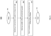
- the method 500 can be implemented in any of the braking systems 100, 200, 300, 400. It should be understood that other configuration can be used to implement the method 500.
- the method 500 begins at block 502 and proceeds to block 504 which operates an electrical braking system in at least one mode.
- the modes can include the pulsed braking mode, the resonance regenerative braking mode, a combination of the pulsed braking and resonance regenerative braking mode, and others.
- Block 506 senses a condition of the electrical braking system.
- the condition that is monitored is a threshold voltage of the DC link.
- a comparator receives an input and compares the input to a reference signal to determine whether the threshold has been exceeded. Subsequently, the output of the comparator can be provided to logic devices to control the drive. It should be understood that other conditions can be monitored.
- braking is performed based at least in part on the at least one mode and the sensed condition. In the event the upper threshold voltage of the DC link is reached and/or exceeded, the electrical braking system functions in the configured mode.
- the method 500 ends at block 510. It should be understood that the steps in FIG. 5 are not intended to limit the scope and additional/different steps can be included in the method 500.
- the technical benefits and effects include implementing pulsed braking resistors and regenerative resonance braking which improves the efficiency of the electric drive.
- the regenerative action can be configured in buck/boost mode for auxiliary load drive.
- the technical benefits and effects also include a sequenced independent control of pulse braking and resonance braking mode with controlled duty cycle. Due to resonance braking, a smaller size brake resistor is sufficient compared to existing braking topologies.
Landscapes
- Engineering & Computer Science (AREA)
- Power Engineering (AREA)
- Transportation (AREA)
- Mechanical Engineering (AREA)
- Life Sciences & Earth Sciences (AREA)
- Sustainable Development (AREA)
- Sustainable Energy (AREA)
- Stopping Of Electric Motors (AREA)
Applications Claiming Priority (1)
| Application Number | Priority Date | Filing Date | Title |
|---|---|---|---|
| IN201911032211 | 2019-08-08 |
Publications (2)
| Publication Number | Publication Date |
|---|---|
| EP3789231A1 true EP3789231A1 (fr) | 2021-03-10 |
| EP3789231B1 EP3789231B1 (fr) | 2023-05-31 |
Family
ID=71950410
Family Applications (1)
| Application Number | Title | Priority Date | Filing Date |
|---|---|---|---|
| EP20189441.7A Active EP3789231B1 (fr) | 2019-08-08 | 2020-08-04 | Freinage par récupération électrique efficace |
Country Status (2)
| Country | Link |
|---|---|
| US (1) | US11142075B2 (fr) |
| EP (1) | EP3789231B1 (fr) |
Families Citing this family (1)
| Publication number | Priority date | Publication date | Assignee | Title |
|---|---|---|---|---|
| US20230374942A1 (en) * | 2022-05-22 | 2023-11-23 | Hamilton Sundstrand Corporation | Engine starter circuits |
Citations (3)
| Publication number | Priority date | Publication date | Assignee | Title |
|---|---|---|---|---|
| GB2459883A (en) * | 2008-05-09 | 2009-11-11 | Siemens Ag | Over-temperature protection system for a braking resistor |
| US20150171674A1 (en) * | 2013-10-27 | 2015-06-18 | Moovee Innovations Inc. | Software-defined electric motor |
| US9722514B2 (en) * | 2014-04-07 | 2017-08-01 | Nidec Control Techniques Limited | Motor drive and method of controlling a temperature of a motor drive |
Family Cites Families (19)
| Publication number | Priority date | Publication date | Assignee | Title |
|---|---|---|---|---|
| DE2220104A1 (de) | 1972-04-25 | 1973-10-31 | Bbc Brown Boveri & Cie | Einrichtung zur kommutierung einer aus zwei teilgleichstromstellern bestehenden anordnung |
| US5332954A (en) | 1992-03-30 | 1994-07-26 | Solaria Research Enterprises Ltd. | Optimal DC motor/controller configuration |
| US6462506B2 (en) | 1999-12-30 | 2002-10-08 | Textron Inc. | Electric golf car with low-speed regenerative braking |
| US6943510B2 (en) | 2001-08-06 | 2005-09-13 | Black & Decker Inc. | Excitation circuit and control method for flux switching motor |
| US7075257B2 (en) | 2002-10-18 | 2006-07-11 | Black & Decker Inc. | Method and device for braking a motor |
| US20070170910A1 (en) | 2006-01-26 | 2007-07-26 | Ming-Hoo Chang | Spectral resistor, spectral capacitor, order-infinity resonant tank, EM wave absorbing material, and applications thereof |
| WO2008051611A2 (fr) | 2006-10-25 | 2008-05-02 | Farkas Laszio | Systeme de transfert d'energie resonant sans fil a haute puissance |
| KR20090118712A (ko) | 2008-05-14 | 2009-11-18 | 국민대학교산학협력단 | 회생 제동 장치 및 그 제어 방법 |
| IT1404232B1 (it) | 2010-12-16 | 2013-11-15 | Gate Srl | Sistema di controllo della velocita' di rotazione di un elettroventilatore associato a scambiatori di calore di un autoveicolo |
| WO2014031112A1 (fr) | 2012-08-22 | 2014-02-27 | Otis Elevator Company | Système d'ascenseur utilisant un freinage dynamique |
| US9428069B2 (en) | 2012-12-26 | 2016-08-30 | Colorado Energy Research Technologies, LLC | Systems and methods for efficiently charging power recovery controller |
| JP2014138532A (ja) | 2013-01-18 | 2014-07-28 | Fuji Electric Co Ltd | 電力変換装置 |
| US9083274B2 (en) * | 2013-04-08 | 2015-07-14 | Rockwell Automation Technologies, Inc. | Power stage precharging and dynamic braking apparatus for multilevel inverter |
| US9035584B2 (en) | 2013-07-02 | 2015-05-19 | The Boeing Company | Quadrant change control in brushless DC motors |
| US9960687B2 (en) | 2016-06-06 | 2018-05-01 | General Electric Company | System and method for a DC/DC converter |
| WO2018123521A1 (fr) * | 2016-12-27 | 2018-07-05 | 株式会社キトー | Palan électrique compatible avec une alimentation électrique à courant alternatif triphasée/monophasée |
| GB2566499B (en) | 2017-09-15 | 2019-12-18 | De Innovation Lab Ltd | Regenerative braking arrangement for electrical vehicles |
| WO2019053270A2 (fr) | 2017-09-15 | 2019-03-21 | Detroit Electric Ev Technologies (Zhejiang) Limited | Véhicule électrique et procédé de fourniture de couple moteur dans un véhicule électrique à l'aide d'au moins deux moteurs électriques |
| US20200332791A1 (en) * | 2019-04-19 | 2020-10-22 | Baker Hughes Oilfield Operations Llc | Regenerated Power Accumulator for Rod Lift Drive |
-
2019
- 2019-10-07 US US16/594,153 patent/US11142075B2/en active Active
-
2020
- 2020-08-04 EP EP20189441.7A patent/EP3789231B1/fr active Active
Patent Citations (3)
| Publication number | Priority date | Publication date | Assignee | Title |
|---|---|---|---|---|
| GB2459883A (en) * | 2008-05-09 | 2009-11-11 | Siemens Ag | Over-temperature protection system for a braking resistor |
| US20150171674A1 (en) * | 2013-10-27 | 2015-06-18 | Moovee Innovations Inc. | Software-defined electric motor |
| US9722514B2 (en) * | 2014-04-07 | 2017-08-01 | Nidec Control Techniques Limited | Motor drive and method of controlling a temperature of a motor drive |
Also Published As
| Publication number | Publication date |
|---|---|
| EP3789231B1 (fr) | 2023-05-31 |
| US11142075B2 (en) | 2021-10-12 |
| US20210039499A1 (en) | 2021-02-11 |
Similar Documents
| Publication | Publication Date | Title |
|---|---|---|
| EP1039625B1 (fr) | Opération d'une machine à reluctance commutée avec tension d'alimentation dual | |
| US7400116B2 (en) | Pre-charging system for smoothing capacitor | |
| US20160380563A1 (en) | Power conversion control apparatus | |
| US9716455B2 (en) | Power conversion device and method of controlling the same | |
| US8030861B2 (en) | Method for controlling a deceleration process of a DC motor and controller | |
| EP3121952B1 (fr) | Moteur à réluctance commutée avec circuit de commande et procédé pour faire fonctionner un moteur à réluctance commutée | |
| CN109478863B (zh) | Sr电动机控制系统和sr电动机控制方法 | |
| JP5288178B2 (ja) | モータ駆動システム | |
| JP5452654B2 (ja) | 車両用交流発電機の制御装置 | |
| US8339075B2 (en) | Method for controlling a deceleration process of a DC motor and controller | |
| JP5396920B2 (ja) | 三相交流電動機駆動システムの巻線切替装置 | |
| EP3789231B1 (fr) | Freinage par récupération électrique efficace | |
| EP1209790B1 (fr) | Entrainement à reluctance commutée alimenté par deux sources de tension et méthode pour commander celui-ci | |
| JP2004523997A (ja) | 発電機の負荷除去時過渡状態の加速 | |
| US8040094B2 (en) | Voltage clamping and energy recovery circuits | |
| CN114123882B (zh) | 单线圈bldc电机的制动 | |
| JP6119531B2 (ja) | 車両用回転電機 | |
| JP5499850B2 (ja) | インバータの放電制御装置 | |
| JP2019140755A (ja) | 結線切換装置 | |
| JP2003199391A (ja) | モータ駆動装置 | |
| US11671048B2 (en) | Multiphase voltage transformer for a supply network and method for powering down an intermediate circuit voltage of this supply network | |
| CN115764813A (zh) | 用于运行电机的方法 | |
| JP2004032998A (ja) | インバータ装置 | |
| JP2003259649A (ja) | 自励式直流電源装置の制御方法 | |
| KR20160019784A (ko) | 모터의 구동장치 및 그 제어방법 |
Legal Events
| Date | Code | Title | Description |
|---|---|---|---|
| PUAI | Public reference made under article 153(3) epc to a published international application that has entered the european phase |
Free format text: ORIGINAL CODE: 0009012 |
|
| STAA | Information on the status of an ep patent application or granted ep patent |
Free format text: STATUS: THE APPLICATION HAS BEEN PUBLISHED |
|
| AK | Designated contracting states |
Kind code of ref document: A1 Designated state(s): AL AT BE BG CH CY CZ DE DK EE ES FI FR GB GR HR HU IE IS IT LI LT LU LV MC MK MT NL NO PL PT RO RS SE SI SK SM TR |
|
| AX | Request for extension of the european patent |
Extension state: BA ME |
|
| STAA | Information on the status of an ep patent application or granted ep patent |
Free format text: STATUS: REQUEST FOR EXAMINATION WAS MADE |
|
| 17P | Request for examination filed |
Effective date: 20210908 |
|
| RBV | Designated contracting states (corrected) |
Designated state(s): AL AT BE BG CH CY CZ DE DK EE ES FI FR GB GR HR HU IE IS IT LI LT LU LV MC MK MT NL NO PL PT RO RS SE SI SK SM TR |
|
| GRAP | Despatch of communication of intention to grant a patent |
Free format text: ORIGINAL CODE: EPIDOSNIGR1 |
|
| STAA | Information on the status of an ep patent application or granted ep patent |
Free format text: STATUS: GRANT OF PATENT IS INTENDED |
|
| INTG | Intention to grant announced |
Effective date: 20221222 |
|
| GRAS | Grant fee paid |
Free format text: ORIGINAL CODE: EPIDOSNIGR3 |
|
| GRAA | (expected) grant |
Free format text: ORIGINAL CODE: 0009210 |
|
| STAA | Information on the status of an ep patent application or granted ep patent |
Free format text: STATUS: THE PATENT HAS BEEN GRANTED |
|
| AK | Designated contracting states |
Kind code of ref document: B1 Designated state(s): AL AT BE BG CH CY CZ DE DK EE ES FI FR GB GR HR HU IE IS IT LI LT LU LV MC MK MT NL NO PL PT RO RS SE SI SK SM TR |
|
| REG | Reference to a national code |
Ref country code: GB Ref legal event code: FG4D Ref country code: CH Ref legal event code: EP |
|
| REG | Reference to a national code |
Ref country code: AT Ref legal event code: REF Ref document number: 1570739 Country of ref document: AT Kind code of ref document: T Effective date: 20230615 Ref country code: DE Ref legal event code: R096 Ref document number: 602020011270 Country of ref document: DE |
|
| REG | Reference to a national code |
Ref country code: IE Ref legal event code: FG4D |
|
| REG | Reference to a national code |
Ref country code: LT Ref legal event code: MG9D |
|
| REG | Reference to a national code |
Ref country code: NL Ref legal event code: MP Effective date: 20230531 |
|
| REG | Reference to a national code |
Ref country code: AT Ref legal event code: MK05 Ref document number: 1570739 Country of ref document: AT Kind code of ref document: T Effective date: 20230531 |
|
| PG25 | Lapsed in a contracting state [announced via postgrant information from national office to epo] |
Ref country code: SE Free format text: LAPSE BECAUSE OF FAILURE TO SUBMIT A TRANSLATION OF THE DESCRIPTION OR TO PAY THE FEE WITHIN THE PRESCRIBED TIME-LIMIT Effective date: 20230531 Ref country code: NO Free format text: LAPSE BECAUSE OF FAILURE TO SUBMIT A TRANSLATION OF THE DESCRIPTION OR TO PAY THE FEE WITHIN THE PRESCRIBED TIME-LIMIT Effective date: 20230831 Ref country code: ES Free format text: LAPSE BECAUSE OF FAILURE TO SUBMIT A TRANSLATION OF THE DESCRIPTION OR TO PAY THE FEE WITHIN THE PRESCRIBED TIME-LIMIT Effective date: 20230531 Ref country code: AT Free format text: LAPSE BECAUSE OF FAILURE TO SUBMIT A TRANSLATION OF THE DESCRIPTION OR TO PAY THE FEE WITHIN THE PRESCRIBED TIME-LIMIT Effective date: 20230531 |
|
| PG25 | Lapsed in a contracting state [announced via postgrant information from national office to epo] |
Ref country code: RS Free format text: LAPSE BECAUSE OF FAILURE TO SUBMIT A TRANSLATION OF THE DESCRIPTION OR TO PAY THE FEE WITHIN THE PRESCRIBED TIME-LIMIT Effective date: 20230531 Ref country code: PL Free format text: LAPSE BECAUSE OF FAILURE TO SUBMIT A TRANSLATION OF THE DESCRIPTION OR TO PAY THE FEE WITHIN THE PRESCRIBED TIME-LIMIT Effective date: 20230531 Ref country code: NL Free format text: LAPSE BECAUSE OF FAILURE TO SUBMIT A TRANSLATION OF THE DESCRIPTION OR TO PAY THE FEE WITHIN THE PRESCRIBED TIME-LIMIT Effective date: 20230531 Ref country code: LV Free format text: LAPSE BECAUSE OF FAILURE TO SUBMIT A TRANSLATION OF THE DESCRIPTION OR TO PAY THE FEE WITHIN THE PRESCRIBED TIME-LIMIT Effective date: 20230531 Ref country code: LT Free format text: LAPSE BECAUSE OF FAILURE TO SUBMIT A TRANSLATION OF THE DESCRIPTION OR TO PAY THE FEE WITHIN THE PRESCRIBED TIME-LIMIT Effective date: 20230531 Ref country code: IS Free format text: LAPSE BECAUSE OF FAILURE TO SUBMIT A TRANSLATION OF THE DESCRIPTION OR TO PAY THE FEE WITHIN THE PRESCRIBED TIME-LIMIT Effective date: 20230930 Ref country code: HR Free format text: LAPSE BECAUSE OF FAILURE TO SUBMIT A TRANSLATION OF THE DESCRIPTION OR TO PAY THE FEE WITHIN THE PRESCRIBED TIME-LIMIT Effective date: 20230531 Ref country code: GR Free format text: LAPSE BECAUSE OF FAILURE TO SUBMIT A TRANSLATION OF THE DESCRIPTION OR TO PAY THE FEE WITHIN THE PRESCRIBED TIME-LIMIT Effective date: 20230901 |
|
| PGFP | Annual fee paid to national office [announced via postgrant information from national office to epo] |
Ref country code: FR Payment date: 20230720 Year of fee payment: 4 Ref country code: DE Payment date: 20230720 Year of fee payment: 4 |
|
| PG25 | Lapsed in a contracting state [announced via postgrant information from national office to epo] |
Ref country code: FI Free format text: LAPSE BECAUSE OF FAILURE TO SUBMIT A TRANSLATION OF THE DESCRIPTION OR TO PAY THE FEE WITHIN THE PRESCRIBED TIME-LIMIT Effective date: 20230531 |
|
| PG25 | Lapsed in a contracting state [announced via postgrant information from national office to epo] |
Ref country code: SK Free format text: LAPSE BECAUSE OF FAILURE TO SUBMIT A TRANSLATION OF THE DESCRIPTION OR TO PAY THE FEE WITHIN THE PRESCRIBED TIME-LIMIT Effective date: 20230531 |
|
| PG25 | Lapsed in a contracting state [announced via postgrant information from national office to epo] |
Ref country code: SM Free format text: LAPSE BECAUSE OF FAILURE TO SUBMIT A TRANSLATION OF THE DESCRIPTION OR TO PAY THE FEE WITHIN THE PRESCRIBED TIME-LIMIT Effective date: 20230531 Ref country code: SK Free format text: LAPSE BECAUSE OF FAILURE TO SUBMIT A TRANSLATION OF THE DESCRIPTION OR TO PAY THE FEE WITHIN THE PRESCRIBED TIME-LIMIT Effective date: 20230531 Ref country code: RO Free format text: LAPSE BECAUSE OF FAILURE TO SUBMIT A TRANSLATION OF THE DESCRIPTION OR TO PAY THE FEE WITHIN THE PRESCRIBED TIME-LIMIT Effective date: 20230531 Ref country code: PT Free format text: LAPSE BECAUSE OF FAILURE TO SUBMIT A TRANSLATION OF THE DESCRIPTION OR TO PAY THE FEE WITHIN THE PRESCRIBED TIME-LIMIT Effective date: 20231002 Ref country code: EE Free format text: LAPSE BECAUSE OF FAILURE TO SUBMIT A TRANSLATION OF THE DESCRIPTION OR TO PAY THE FEE WITHIN THE PRESCRIBED TIME-LIMIT Effective date: 20230531 Ref country code: DK Free format text: LAPSE BECAUSE OF FAILURE TO SUBMIT A TRANSLATION OF THE DESCRIPTION OR TO PAY THE FEE WITHIN THE PRESCRIBED TIME-LIMIT Effective date: 20230531 Ref country code: CZ Free format text: LAPSE BECAUSE OF FAILURE TO SUBMIT A TRANSLATION OF THE DESCRIPTION OR TO PAY THE FEE WITHIN THE PRESCRIBED TIME-LIMIT Effective date: 20230531 |
|
| REG | Reference to a national code |
Ref country code: DE Ref legal event code: R097 Ref document number: 602020011270 Country of ref document: DE |
|
| PG25 | Lapsed in a contracting state [announced via postgrant information from national office to epo] |
Ref country code: MC Free format text: LAPSE BECAUSE OF FAILURE TO SUBMIT A TRANSLATION OF THE DESCRIPTION OR TO PAY THE FEE WITHIN THE PRESCRIBED TIME-LIMIT Effective date: 20230531 |
|
| REG | Reference to a national code |
Ref country code: CH Ref legal event code: PL |
|
| PG25 | Lapsed in a contracting state [announced via postgrant information from national office to epo] |
Ref country code: MC Free format text: LAPSE BECAUSE OF FAILURE TO SUBMIT A TRANSLATION OF THE DESCRIPTION OR TO PAY THE FEE WITHIN THE PRESCRIBED TIME-LIMIT Effective date: 20230531 |
|
| PLBE | No opposition filed within time limit |
Free format text: ORIGINAL CODE: 0009261 |
|
| STAA | Information on the status of an ep patent application or granted ep patent |
Free format text: STATUS: NO OPPOSITION FILED WITHIN TIME LIMIT |
|
| PG25 | Lapsed in a contracting state [announced via postgrant information from national office to epo] |
Ref country code: LU Free format text: LAPSE BECAUSE OF NON-PAYMENT OF DUE FEES Effective date: 20230804 |
|
| PG25 | Lapsed in a contracting state [announced via postgrant information from national office to epo] |
Ref country code: LU Free format text: LAPSE BECAUSE OF NON-PAYMENT OF DUE FEES Effective date: 20230804 Ref country code: CH Free format text: LAPSE BECAUSE OF NON-PAYMENT OF DUE FEES Effective date: 20230831 |
|
| PG25 | Lapsed in a contracting state [announced via postgrant information from national office to epo] |
Ref country code: SI Free format text: LAPSE BECAUSE OF FAILURE TO SUBMIT A TRANSLATION OF THE DESCRIPTION OR TO PAY THE FEE WITHIN THE PRESCRIBED TIME-LIMIT Effective date: 20230531 |
|
| REG | Reference to a national code |
Ref country code: BE Ref legal event code: MM Effective date: 20230831 |
|
| 26N | No opposition filed |
Effective date: 20240301 |
|
| REG | Reference to a national code |
Ref country code: IE Ref legal event code: MM4A |