EP3787120A1 - Kontakteinsatz einer leiteranschlussklemme und leiteranschlussklemme - Google Patents
Kontakteinsatz einer leiteranschlussklemme und leiteranschlussklemme Download PDFInfo
- Publication number
- EP3787120A1 EP3787120A1 EP20187463.3A EP20187463A EP3787120A1 EP 3787120 A1 EP3787120 A1 EP 3787120A1 EP 20187463 A EP20187463 A EP 20187463A EP 3787120 A1 EP3787120 A1 EP 3787120A1
- Authority
- EP
- European Patent Office
- Prior art keywords
- busbar
- contact insert
- conductor
- perforated collar
- perforated
- Prior art date
- Legal status (The legal status is an assumption and is not a legal conclusion. Google has not performed a legal analysis and makes no representation as to the accuracy of the status listed.)
- Granted
Links
Images

Classifications
-
- H—ELECTRICITY
- H01—ELECTRIC ELEMENTS
- H01R—ELECTRICALLY-CONDUCTIVE CONNECTIONS; STRUCTURAL ASSOCIATIONS OF A PLURALITY OF MUTUALLY-INSULATED ELECTRICAL CONNECTING ELEMENTS; COUPLING DEVICES; CURRENT COLLECTORS
- H01R9/00—Structural associations of a plurality of mutually-insulated electrical connecting elements, e.g. terminal strips or terminal blocks; Terminals or binding posts mounted upon a base or in a case; Bases therefor
- H01R9/22—Bases, e.g. strip, block, panel
- H01R9/24—Terminal blocks
- H01R9/26—Clip-on terminal blocks for side-by-side rail- or strip-mounting
-
- H—ELECTRICITY
- H01—ELECTRIC ELEMENTS
- H01R—ELECTRICALLY-CONDUCTIVE CONNECTIONS; STRUCTURAL ASSOCIATIONS OF A PLURALITY OF MUTUALLY-INSULATED ELECTRICAL CONNECTING ELEMENTS; COUPLING DEVICES; CURRENT COLLECTORS
- H01R9/00—Structural associations of a plurality of mutually-insulated electrical connecting elements, e.g. terminal strips or terminal blocks; Terminals or binding posts mounted upon a base or in a case; Bases therefor
- H01R9/22—Bases, e.g. strip, block, panel
- H01R9/24—Terminal blocks
-
- H—ELECTRICITY
- H01—ELECTRIC ELEMENTS
- H01R—ELECTRICALLY-CONDUCTIVE CONNECTIONS; STRUCTURAL ASSOCIATIONS OF A PLURALITY OF MUTUALLY-INSULATED ELECTRICAL CONNECTING ELEMENTS; COUPLING DEVICES; CURRENT COLLECTORS
- H01R13/00—Details of coupling devices of the kinds covered by groups H01R12/70 or H01R24/00 - H01R33/00
- H01R13/40—Securing contact members in or to a base or case; Insulating of contact members
-
- H—ELECTRICITY
- H01—ELECTRIC ELEMENTS
- H01R—ELECTRICALLY-CONDUCTIVE CONNECTIONS; STRUCTURAL ASSOCIATIONS OF A PLURALITY OF MUTUALLY-INSULATED ELECTRICAL CONNECTING ELEMENTS; COUPLING DEVICES; CURRENT COLLECTORS
- H01R25/00—Coupling parts adapted for simultaneous co-operation with two or more identical counterparts, e.g. for distributing energy to two or more circuits
- H01R25/14—Rails or bus-bars constructed so that the counterparts can be connected thereto at any point along their length
-
- H—ELECTRICITY
- H01—ELECTRIC ELEMENTS
- H01R—ELECTRICALLY-CONDUCTIVE CONNECTIONS; STRUCTURAL ASSOCIATIONS OF A PLURALITY OF MUTUALLY-INSULATED ELECTRICAL CONNECTING ELEMENTS; COUPLING DEVICES; CURRENT COLLECTORS
- H01R31/00—Coupling parts supported only by co-operation with counterpart
- H01R31/08—Short-circuiting members for bridging contacts in a counterpart
- H01R31/085—Short circuiting bus-strips
-
- H—ELECTRICITY
- H01—ELECTRIC ELEMENTS
- H01R—ELECTRICALLY-CONDUCTIVE CONNECTIONS; STRUCTURAL ASSOCIATIONS OF A PLURALITY OF MUTUALLY-INSULATED ELECTRICAL CONNECTING ELEMENTS; COUPLING DEVICES; CURRENT COLLECTORS
- H01R4/00—Electrically-conductive connections between two or more conductive members in direct contact, i.e. touching one another; Means for effecting or maintaining such contact; Electrically-conductive connections having two or more spaced connecting locations for conductors and using contact members penetrating insulation
- H01R4/28—Clamped connections, spring connections
- H01R4/48—Clamped connections, spring connections utilising a spring, clip, or other resilient member
- H01R4/4809—Clamped connections, spring connections utilising a spring, clip, or other resilient member using a leaf spring to bias the conductor toward the busbar
- H01R4/48185—Clamped connections, spring connections utilising a spring, clip, or other resilient member using a leaf spring to bias the conductor toward the busbar adapted for axial insertion of a wire end
- H01R4/4819—Clamped connections, spring connections utilising a spring, clip, or other resilient member using a leaf spring to bias the conductor toward the busbar adapted for axial insertion of a wire end the spring shape allowing insertion of the conductor end when the spring is unbiased
- H01R4/4821—Single-blade spring
-
- H—ELECTRICITY
- H01—ELECTRIC ELEMENTS
- H01R—ELECTRICALLY-CONDUCTIVE CONNECTIONS; STRUCTURAL ASSOCIATIONS OF A PLURALITY OF MUTUALLY-INSULATED ELECTRICAL CONNECTING ELEMENTS; COUPLING DEVICES; CURRENT COLLECTORS
- H01R4/00—Electrically-conductive connections between two or more conductive members in direct contact, i.e. touching one another; Means for effecting or maintaining such contact; Electrically-conductive connections having two or more spaced connecting locations for conductors and using contact members penetrating insulation
- H01R4/28—Clamped connections, spring connections
- H01R4/48—Clamped connections, spring connections utilising a spring, clip, or other resilient member
- H01R4/4809—Clamped connections, spring connections utilising a spring, clip, or other resilient member using a leaf spring to bias the conductor toward the busbar
- H01R4/4846—Busbar details
- H01R4/485—Single busbar common to multiple springs
-
- H—ELECTRICITY
- H01—ELECTRIC ELEMENTS
- H01R—ELECTRICALLY-CONDUCTIVE CONNECTIONS; STRUCTURAL ASSOCIATIONS OF A PLURALITY OF MUTUALLY-INSULATED ELECTRICAL CONNECTING ELEMENTS; COUPLING DEVICES; CURRENT COLLECTORS
- H01R4/00—Electrically-conductive connections between two or more conductive members in direct contact, i.e. touching one another; Means for effecting or maintaining such contact; Electrically-conductive connections having two or more spaced connecting locations for conductors and using contact members penetrating insulation
- H01R4/28—Clamped connections, spring connections
- H01R4/48—Clamped connections, spring connections utilising a spring, clip, or other resilient member
- H01R4/4809—Clamped connections, spring connections utilising a spring, clip, or other resilient member using a leaf spring to bias the conductor toward the busbar
- H01R4/4828—Spring-activating arrangements mounted on or integrally formed with the spring housing
- H01R4/4833—Sliding arrangements, e.g. sliding button
-
- H—ELECTRICITY
- H01—ELECTRIC ELEMENTS
- H01R—ELECTRICALLY-CONDUCTIVE CONNECTIONS; STRUCTURAL ASSOCIATIONS OF A PLURALITY OF MUTUALLY-INSULATED ELECTRICAL CONNECTING ELEMENTS; COUPLING DEVICES; CURRENT COLLECTORS
- H01R4/00—Electrically-conductive connections between two or more conductive members in direct contact, i.e. touching one another; Means for effecting or maintaining such contact; Electrically-conductive connections having two or more spaced connecting locations for conductors and using contact members penetrating insulation
- H01R4/28—Clamped connections, spring connections
- H01R4/48—Clamped connections, spring connections utilising a spring, clip, or other resilient member
- H01R4/4809—Clamped connections, spring connections utilising a spring, clip, or other resilient member using a leaf spring to bias the conductor toward the busbar
- H01R4/484—Spring housing details
Definitions
- the invention relates to a contact insert of a conductor connection terminal for connecting at least one electrical conductor, the contact insert having at least one busbar and at least one clamping spring.
- the invention also relates to a conductor connection terminal with such a contact insert.
- the invention thus relates to the field of conductor connection technology by means of clamping springs.
- Such conductor connection terminals are for example from the DE 10 2010 051 899 B4 known.
- the invention is based on the object of further optimizing such a contact insert and a conductor connection terminal, for example with regard to the structural size, the manufacture and / or the assembly.
- a contact insert of a conductor connection terminal for connecting at least one electrical conductor the contact insert having at least one busbar and at least one clamping spring, the busbar having at least one through opening, the contact insert having a perforated collar, which is a separate component from the busbar is formed, wherein the perforated collar on at least one side of the busbar surrounds the through opening at least partially or completely circumferentially.
- the perforated collar on at least one side of the busbar surrounds the through opening at least partially or completely circumferentially.
- the formation of several material passages on the busbar is only possible to a limited extent, with a certain minimum distance between the through-openings of the busbar in particular having to be present.
- the perforated collar in which the perforated collar is designed as a component separate from the busbar, the material of the busbar can be left unchanged.
- the separate component that forms the perforated collar can be shaped as desired, so that in particular contact inserts can be created in which several closely adjacent through openings are each equipped with a perforated collar on the busbar. In this way, for example, a compact conductor connection terminal with a multiplicity of terminal points or through openings arranged close to one another can be provided.
- the step of manufacturing the material passage for forming the perforated collar can be saved. Instead, the separate component that is to form the perforated collar can be used. This can be designed very simply, e.g. as a plastic component.
- the clamping spring together with the busbar, can provide a clamping point for the electrical conductor to be clamped in the area of the through opening.
- This can be implemented, for example, in such a way that a clamping leg of the clamping spring protrudes into the through opening or protrudes through the through opening.
- the electrical conductor to be clamped can then be clamped between the clamping leg and the edge of the through opening or a tab formed there.
- the contact insert can be designed as a spring-loaded terminal connection.
- the perforated collar surrounding the through opening also provides a conductor chamber in which the electrical conductor to be connected can at least in part be received and guided.
- the perforated collar consists of a different material than the busbar.
- the perforated collar can in particular consist of a non-metallic material and / or an electrically insulating material, for example plastic. This allows a simple and inexpensive production of the perforated collar with a low weight at the same time.
- the perforated collar can be fixed relative to the busbar in various ways, e.g. by attaching the perforated collar to the clamping spring or to other parts of the conductor connection terminal.
- the perforated collar can be fixed by parts of a housing of the conductor connection terminal.
- the separate component forming the perforated collar is attached to the busbar.
- the busbar with the perforated collar can form a complete structural unit from which the perforated collar cannot easily be detached again.
- the busbar with the perforated collar can be provided as a preassembled unit.
- no other fastening measures are required to fix the perforated collar, for example fastening arrangements on a housing of a conductor connection terminal.
- the separate component forming the perforated collar is fastened to the busbar by clamping, latching, gluing or a combination thereof. This allows both simple assembly of the elements of the contact insert and a secure permanent connection between the perforated collar and the busbar.
- the busbar and / or the perforated collar can have respective fixing elements by means of which the perforated collar can be fixed to the busbar. If the perforated collar and the busbar have fixing elements, then these can be designed as counterparts that are assigned to one another, for example as latching hooks / latching edges.
- the perforated collar is designed to be circumferential, forming a through hole.
- the material of the perforated collar thus surrounds the through hole at least in sections or completely on the circumferential side.
- the through hole of the perforated collar is aligned with the through opening of the busbar.
- the electrical conductor can be guided through the through opening of the busbar and the through hole of the perforated collar without hindrance.
- the perforated collar can form a guide for the electrical conductor.
- the perforated collar is designed as a conductor guide element, which on the circumference at least partially or completely forms a conductor guide for an electrical conductor to be connected to the contact insert.
- the perforated collar does not have to be flush with the through opening of the busbar on all sides.
- a long side could be missing and formed by an edge / shoulder in the housing of the conductor connection terminal.
- the separate component forming the perforated collar has a conductor stop for the electrical conductor to be clamped and / or an overload stop to limit the maximum deflection of the clamping spring.
- the component forming the perforated collar can take over the provision of further functions in the conductor chamber, namely the conductor stop and / or the overload stop.
- Such a conductor stop can mechanically limit the maximum insertion depth of an electrical conductor into the conductor connection terminal.
- the overload stop forms a mechanical limitation of the maximum deflection of the clamping spring. Accordingly, no additional features or components are required on the contact insert to form such functions.
- At least one area of the perforated collar protrudes into the area of the through opening.
- This protruding area is well suited to form the overload stop mentioned.
- the inner edge of the through hole of the perforated collar below the spring arch of the clamping spring can be shifted into the area of the through opening and serve as an (overload) stop for the clamping leg.
- the busbar has several through openings one behind the other and / or several through openings next to one another in the longitudinal direction, with several or all of the through openings having a respective perforated collar and, together with a respective clamping spring, providing a respective clamping point for an electrical conductor to be clamped , wherein the perforated collars are designed as a common separate component or a plurality of components separate from the busbar.
- the direction of the longitudinal extent of the busbar is understood to mean the direction of the largest longitudinal dimension of the busbar. In this way, a particularly small contact insert with a large number of clamping points can be provided, at which several electrical conductors can each be clamped.
- the individual perforated collars can each be designed as individual, separate components. Several or all of the perforated collars can also be combined to form a common component, e.g. a plastic component. Such a component having a plurality of perforated collars can, for example, be designed in the form of a grid with a plurality of through holes arranged in a matrix-like manner.
- the busbar in the area of the through opening has a clamping strap formed from the material of the busbar and angled relative to the surface of the busbar, on which the clamping point is formed together with the clamping spring.
- the clamping spring can, for example, have a clamping edge at the free end of its clamping leg, whereby a particularly secure clamping of an electrical conductor at the clamping point can be ensured.
- the contact tab can be planar, convex or concave on the surface facing the clamping leg of the clamping spring.
- a concave design has the advantage that a recess is formed in which the clamping leg can be supported with the clamping edge in the rest position, i.e. a defined bearing point is provided for the clamping edge.
- the clamping tab extends at least partially into the space surrounded by the perforated collar.
- the clamping lug can protrude into the space enclosed by the perforated collar or protrude through it, i.e. protrude again on the other side of the perforated collar. In this way, the electrical contacting of the electrical conductor at the terminal point can be further improved.
- a conductor connection terminal for connecting at least one electrical conductor, the conductor connection terminal having a housing and a contact insert of the type explained above.
- the at least one busbar and the at least one clamping spring are arranged at least predominantly within the housing.
- the housing can, for example, be designed as an insulating material housing.
- the indefinite term “a” is not to be understood as a numerical word. If, for example, a component is mentioned, this is to be interpreted in the sense of "at least one component”. As far as angles are given in degrees, these refer to a circle of 360 degrees (360 °).
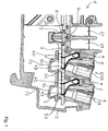
- the visible conductor connection terminal 1 has a housing 2.
- Conductor insertion channels 20 through which electrical conductors can be inserted into the housing 2 are formed on the housing 2.
- jumper shafts 21 are formed on the housing 2, through which electrical jumpers can be connected to electrical elements within the housing 2.
- a contact insert of the conductor connection terminal 1 is arranged in the housing 2 and has a busbar 3, clamping springs 4, perforated collar 6, jumper springs 7 and a jumper spring fixing element 8.
- the busbar 3 is designed as an elongated flat metal part in which one or more through openings 30 are present.
- a clamping spring 4 is assigned to a respective through opening 30, the respective clamping spring 4 together with the busbar 3 in the area of the respective through opening 30 providing a clamping point for an electrical conductor to be clamped.
- the busbar 3 has in the area of a through opening 30 a clamping lug 31 formed from the material of the busbar 3 and angled in the direction of a conductor insertion direction E relative to the surface of the busbar 3.
- the clamping spring 4 rests with a respective clamping leg 43 on the respective clamping lug 31 when no electrical conductor is clamped there.
- an electrical conductor If an electrical conductor is clamped there, it is pressed by the clamping leg 43 against the clamping point in the area of the clamping lug 31.
- the respective clamping spring 4 is counter-supported via a contact leg 40, i.e. supported against the clamping force of the clamping leg 43.
- the contact leg 40 can be suspended in the through opening 30 of the busbar 3, for example.
- each clamping spring 4 is assigned an actuating element 5, for example in the form of a trigger or actuating lever.
- actuating the actuating element 5 the clamping leg 43 can be deflected and released from the clamping lug 31 can be moved so that an electrical conductor can be inserted there or removed again without any effort.
- a respective through opening 30 is surrounded by a perforated collar 6.
- the perforated collar 6 is designed as a separate component from the busbar 3.
- the bridging springs 7 are held in a desired position relative to the busbar 3 via the bridging spring fixing element 8.
- the bridging spring fixing element 8 can have a fixing extension 9 which is inserted through an opening in the busbar 3 in order to fasten the bridging spring fixing element 8 to the busbar 3.
- conductor receiving pockets 22 Seen in the conductor insertion direction E, behind the busbar 3 there are conductor receiving pockets 22 which each serve to receive an electrical conductor clamped to the contact insert.
- the conductor receiving pockets 22 can be formed as part of the housing 2, for example.
- the Figure 2 shows the contact insert of the conductor connection terminal 1 with further details. It can be seen in particular that a respective clamping spring 4 is connected to the respective clamping limb 43 starting from the contact limb 40 via a spring bow 42.
- a perforated collar surrounding a respective through opening 30 can, however, also be designed as a single component or as a combined component which provides perforated collars for several adjacent through openings 30.
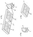
- FIG. 3 shows an example in which the component provides the perforated collars 6 for two through openings 30 which are arranged next to one another.
- the component has two through holes 60 which can be assigned to two through openings 30 of the busbar 3.
- the component formed in this way can form the corresponding perforated collars of two adjacent through openings of the busbar that are arranged next to one another.
- the through openings 30 in the busbar 3 and the through holes 60 of the perforated collar 6 can be arranged in alignment.
- the dimensions of the through hole 60 are greater than the dimension of the through opening 30, at least in the longitudinal direction L. This ensures that a free end of the contact leg 40 and the clamping lug 31 can dip into the through hole 60.
- two of the in Figure 3 Components shown are arranged one behind the other in the longitudinal direction L of the busbar 3.
- the Figure 4 shows an example of the bridging spring fixing element 8 with the fixing extension 9 as a separate component.
- the component forming the perforated collars 6 can also be designed in one piece as a component with the bridging spring fixing element 8, in that this is connected to the component forming the perforated collars 6 via a material bridge 10.
- the Figure 5 also shows an embodiment in which the perforated collars 6 of all (four) through openings 30 of the busbar are implemented as one component.
- the component accordingly has four through holes 60.
- the Figure 5 also shows a perforated collar fixing element 61 with which the component 6 forming the perforated collar can be attached to the busbar 3.
- the perforated collar fixing element 61 can be designed, for example, as a latching projection which can be latched into a latching opening in the busbar 3.
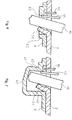
- the Figure 6 shows an electrical conductor 10 inserted into the terminal point Figure 6
- the illustrated embodiment of the contact insert has a perforated collar 6, which not only, as described above, extends as a flat planar part along the busbar 3, but also has at least one vertical wall 62, which extends away from the busbar 3 in a substantially vertical direction .
- the advantageous effects of the perforated collar 6, in particular the conductor routing properties for the electrical conductor 10, can be further improved.
- the Figure 6 shows, as a further additional feature of the perforated collar 6, a spring overload protection, for example in the form of an overload stop 63, which ensures that the clamping leg 43 of the clamping spring 4 cannot be deflected too far and accordingly cannot be damaged. Thus, the clamping spring 4 cannot be overloaded.
- the overload stop 63 can be designed, for example, as a lateral contact surface of the perforated collar 6, with which the clamping leg 43 comes to rest when the maximum permissible deflection is reached.
- the aforementioned overload stop 63 can be implemented, for example, on the vertical wall 62 or also independently of a vertical wall, even if this should be present.
- the Figure 7 again shows the overload stop 63 as part of the perforated collar 6, as explained above.
- the vertical wall 62 is lengthened even further and extends up to a horizontal wall 64 which extends over to an opposite vertical wall 62 of the perforated collar 6.
- the perforated collar 6 can also form a type of conductor receiving pocket for the electrical conductor 10.
- the conductor receiving pocket can be designed as a completely closed cup-shaped structure or with interruptions or openings.
- the horizontal wall 64 also forms a conductor stop for the electrical conductor 10, by means of which the insertion depth of the electrical conductor 10 is limited.
Landscapes
- Connections Arranged To Contact A Plurality Of Conductors (AREA)
- Connector Housings Or Holding Contact Members (AREA)
- Connection Or Junction Boxes (AREA)
Abstract
Description
- Die Erfindung betrifft einen Kontakteinsatz einer Leiteranschlussklemme zum Anschluss wenigstens eines elektrischen Leiters, wobei der Kontakteinsatz wenigstens eine Stromschiene und wenigstens eine Klemmfeder aufweist. Die Erfindung betrifft außerdem eine Leiteranschlussklemme mit einem solchen Kontakteinsatz.
- Die Erfindung betrifft damit das Gebiet der Leiteranschlusstechnik mittels Klemmfedern. Derartige Leiteranschlussklemmen sind beispielsweise aus der
DE 10 2010 051 899 B4 bekannt. - Der Erfindung liegt die Aufgabe zugrunde, einen solchen Kontakteinsatz und eine Leiteranschlussklemme noch weiter zu optimieren, beispielsweise hinsichtlich der Baugröße, der Herstellung und/oder der Montage.
- Diese Aufgabe wird gelöst durch einen Kontakteinsatz einer Leiteranschlussklemme zum Anschluss wenigstens eines elektrischen Leiters, wobei der Kontakteinsatz wenigstens eine Stromschiene und wenigstens eine Klemmfeder aufweist, wobei die Stromschiene wenigstens eine Durchgangsöffnung aufweist, wobei der Kontakteinsatz einen Lochkragen aufweist, der als von der Stromschiene separates Bauteil ausgebildet ist, wobei der Lochkragen auf zumindest einer Seite der Stromschiene die Durchgangsöffnung zumindest abschnittsweise oder vollständig umlaufend umgibt. Im Unterschied zum Stand der Technik, bei dem ein solcher Lochkragen als Materialdurchzug der Stromschiene ausgebildet ist und damit zwangsläufig einstückig mit der Stromschiene ausgeformt ist, wird hiermit der Einsatz eines separaten Bauteils zur Bildung des Lochkragens vorgeschlagen. Auch wenn sich hierdurch auf den ersten Blick scheinbar die Komplexität des Kontakteinsatzes bzw. der Leiteranschlussklemme erhöht, lassen sich durch eine solche Gestaltung dennoch viele Vorteile erzielen.
- So ist beispielsweise die Bildung von mehreren Materialdurchzügen an der Stromschiene nur in begrenztem Umfang möglich, wobei insbesondere ein gewisser Mindestabstand zwischen den Durchgangsöffnungen der Stromschiene vorhanden sein muss. Bei der erfindungsgemäßen Lösung, bei der der Lochkragen als von der Stromschiene separates Bauteil ausgebildet ist, kann das Material der Stromschiene unverändert gelassen werden. Stattdessen kann das separate Bauteil, das den Lochkragen bildet, beliebig geformt werden, so dass insbesondere auch Kontakteinsätze geschaffen werden können, bei denen an der Stromschiene mehrere eng benachbarte Durchgangsöffnungen jeweils mit einem Lochkragen ausgestattet werden. Auf diese Weise kann beispielsweise eine kleinbauende Leiteranschlussklemme mit einer Vielzahl von nahe beieinander angeordneten Klemmstellen bzw. Durchgangsöffnungen bereitgestellt werden.
- Im Herstellungsprozess kann der Schritt des Herstellens des Materialdurchzugs zur Bildung des Lochkragens eingespart werden. Stattdessen kann das separate Bauteil, das den Lochkragen bilden soll, eingesetzt werden. Dieses kann sehr einfach ausgebildet sein, z.B. als Kunststoff-Bauteil.
- Die Klemmfeder kann dabei zusammen mit der Stromschiene im Bereich der Durchgangsöffnung eine Klemmstelle für den anzuklemmenden elektrischen Leiter bereitstellen. Dies kann z.B. derart realisiert sein, dass ein Klemmschenkel der Klemmfeder in die Durchgangsöffnung hineinragt oder durch die Durchgangsöffnung hindurch ragt. Der anzuklemmende elektrische Leiter kann dann zwischen dem Klemmschenkel und dem Rand der Durchgangsöffnung oder einer dort gebildeten Lasche festgeklemmt werden. Der Kontakteinsatz kann als Federkraftklemmanschluss ausgebildet sein.
- Durch den die Durchgangsöffnung umgebenden Lochkragen wird zudem eine Leiterkammer bereitgestellt, in der der anzuschließende elektrische Leiter zumindest zum Teil aufgenommen werden kann und geführt sein kann.
- Gemäß einer vorteilhaften Ausgestaltung der Erfindung ist vorgesehen, dass der Lochkragen aus einem anderen Material besteht als die Stromschiene. Der Lochkragen kann insbesondere aus einem nicht-metallischen Material und/oder einem elektrisch isolierenden Material bestehen, z.B. aus Kunststoff. Dies erlaubt eine einfache und kostengünstige Herstellung des Lochkragens mit zugleich geringem Gewicht.
- Der Lochkragen kann auf verschiedene Arten relativ zur Stromschiene fixiert sein, z.B. dadurch, dass der Lochkragen an der Klemmfeder oder an anderen Teilen der Leiteranschlussklemme befestigt ist. Beispielsweise kann der Lochkragen durch Teile eines Gehäuses der Leiteranschlussklemme fixiert sein.
- Gemäß einer vorteilhaften Ausgestaltung der Erfindung ist vorgesehen, dass das den Lochkragen bildende separate Bauteil an der Stromschiene befestigt ist. Dies hat den Vorteil, dass die Stromschiene mit dem Lochkragen eine komplette Baueinheit bilden kann, von der der Lochkragen sich nicht ohne weiteres wieder löst. Beispielsweise kann die Stromschiene mit dem Lochkragen als vormontierte Einheit bereitgestellt werden. Zudem sind keine sonstigen Befestigungsmaßnahmen zur Fixierung des Lochkragens erforderlich, beispielsweise Befestigungsanordnungen an einem Gehäuse einer Leiteranschlussklemme.
- Gemäß einer vorteilhaften Ausgestaltung der Erfindung ist vorgesehen, dass das den Lochkragen bildende separate Bauteil durch Klemmung, Rastung, Verklebung oder eine Kombination daraus an der Stromschiene befestigt ist. Dies erlaubt sowohl eine einfache Montage der Elemente des Kontakteinsatzes als auch eine sichere dauerhafte Verbindung zwischen dem Lochkragen und der Stromschiene.
- So können die Stromschiene und/oder der Lochkragen jeweilige Fixierelemente aufweisen, durch die der Lochkragen an der Stromschiene fixiert werden kann. Weisen der Lochkragen und die Stromschiene Fixierelemente auf, so können diese als einander zugeordnete Gegenstücke ausgebildet sein, beispielsweise als Rasthaken/ Rastkante.
- Gemäß einer vorteilhaften Ausgestaltung der Erfindung ist vorgesehen, dass der Lochkragen unter Bildung eines Durchgangsloches umlaufend ausgebildet ist. Das Material des Lochkragens umgibt somit umfangsseitig das Durchgangsloch zumindest abschnittsweise oder vollständig.
- Gemäß einer vorteilhaften Ausgestaltung der Erfindung ist vorgesehen, dass das Durchgangsloch des Lochkragens mit der Durchgangsöffnung der Stromschiene fluchtet. Auf diese Weise kann der elektrische Leiter ohne Behinderung durch die Durchgangsöffnung der Stromschiene und das Durchgangsloch des Lochkragens geführt werden. Der Lochkragen kann hierbei eine Führung für den elektrischen Leiter bilden.
- Gemäß einer vorteilhaften Ausgestaltung der Erfindung ist daher vorgesehen, dass der Lochkragen als Leiterführungselement ausgebildet ist, das umfangsseitig zumindest abschnittsweise oder vollständig eine Leiterführung für einen am Kontakteinsatz anzuschließenden elektrischen Leiter bildet.
- Der Lochkragen muss nicht mit allen Seiten mit der Durchgangsöffnung der Stromschiene fluchten. So könnte z.B. eine Längsseite fehlen und durch eine Kante/Absatz im Gehäuse der Leiteranschlussklemme gebildet werden.
- Gemäß einer vorteilhaften Ausgestaltung der Erfindung ist vorgesehen, dass das den Lochkragen bildende separate Bauteil einen Leiteranschlag für den anzuklemmenden elektrischen Leiter und/oder einen Überlastanschlag zur Begrenzung der maximalen Auslenkung der Klemmfeder aufweist. Auf diese Weise kann das den Lochkragen bildende Bauteil die Bereitstellung weiterer Funktionen in der Leiterkammer übernehmen, nämlich den Leiteranschlag und/oder den Überlastanschlag. Durch einen solchen Leiteranschlag kann die maximale Einführtiefe eines elektrischen Leiters in die Leiteranschlussklemme mechanisch begrenzt werden. Der Überlastanschlag bildet eine mechanische Begrenzung der maximalen Auslenkung der Klemmfeder. Dementsprechend sind keine zusätzlichen Merkmale oder Bauteile an dem Kontakteinsatz zur Bildung solcher Funktionen erforderlich.
- Gemäß einer vorteilhaften Ausgestaltung der Erfindung ist vorgesehen, dass zumindest ein Bereich des Lochkragens in den Bereich der Durchgangsöffnung hineinragt. Dieser hineinragende Bereich eignet sich gut, um den erwähnten Überlastanschlag zu bilden. Es kann z.B. die innere Randkante des Durchgangslochs des Lochkragens unterhalb des Federbogens der Klemmfeder in den Bereich der Durchgangsöffnung verlagert sein und als (Überlast-) Anschlag für den Klemmschenkel dienen.
- Gemäß einer vorteilhaften Ausgestaltung der Erfindung ist vorgesehen, dass die Stromschiene in Längserstreckungsrichtung mehrere Durchgangsöffnungen hintereinander und/oder mehrere Durchgangsöffnungen nebeneinander aufweist, wobei mehrere oder alle der Durchgangsöffnungen einen jeweiligen Lochkragen aufweisen und zusammen mit einer jeweiligen Klemmfeder eine jeweilige Klemmstelle für einen anzuklemmenden elektrischen Leiter bereitstellen, wobei die Lochkragen als ein gemeinsames separates Bauteil oder mehrere von der Stromschiene separate Bauteile ausgebildet sind. Als Längserstreckungsrichtung der Stromschiene wird dabei die Richtung der größten Längsabmessung der Stromschiene verstanden. Auf diese Weise kann ein besonders klein bauender Kontakteinsatz mit einer Vielzahl von Klemmstellen bereitgestellt werden, an denen mehrere elektrische Leiter jeweils angeklemmt werden können. Dabei können die einzelnen Lochkragen jeweils als einzelne, separate Bauelemente ausgebildet sein. Es können auch mehrere oder alle Lochkragen zu einem gemeinsamen Bauteil zusammengefasst sein, z.B. einem Kunststoffbauteil. Ein solches mehrere Lochkragen aufweisendes Bauteil kann z.B. gitterförmig mit mehreren matrixartig angeordneten Durchgangslöchern ausgebildet sein.
- Gemäß einer vorteilhaften Ausgestaltung der Erfindung ist vorgesehen, dass die Stromschiene im Bereich der Durchgangsöffnung eine aus dem Material der Stromschiene ausgeformte und gegenüber der Oberfläche der Stromschiene abgewinkelte Klemmlasche aufweist, an der zusammen mit der Klemmfeder die Klemmstelle gebildet ist. Dies erlaubt eine besonders zuverlässige Klemmung eines elektrischen Leiters mit geringem Übergangswiderstand. Die Klemmfeder kann beispielsweise am freien Ende ihres Klemmschenkels eine Klemmkante aufweisen, wodurch eine besonders sichere Klemmung eines elektrischen Leiters an der Klemmstelle gewährleistet werden kann.
- Die Kontaktlasche kann auf der zum Klemmschenkel der Klemmfeder gerichteten Oberfläche plan, konvex oder konkav ausgebildet sein. Eine konkave Ausbildung hat den Vorteil, dass eine Vertiefung gebildet ist, in der der Klemmschenkel mit der Klemmkante in der Ruhestellung gelagert sein kann, d.h. es wird eine definierte Lagerstelle für die Klemmkante bereitgestellt.
- Gemäß einer vorteilhaften Ausgestaltung der Erfindung ist vorgesehen, dass die Klemmlasche sich zumindest teilweise in den vom Lochkragen umgebenen Raum erstreckt. Dabei kann die Klemmlasche in den vom Lochkragen umschlossenen Raum hineinragen oder durch ihn hindurchragen, d.h. auf der anderen Seite des Lochkragens wieder hervorragen. Hierdurch kann die elektrische Kontaktierung des elektrischen Leiters an der Klemmstelle weiter verbessert werden.
- Die eingangs genannte Aufgabe wird außerdem gelöst durch eine Leiteranschlussklemme zum Anschluss wenigstens eines elektrischen Leiters, wobei die Leiteranschlussklemme ein Gehäuse und einen Kontakteinsatz der zuvor erläuterten Art aufweist. Gemäß einer vorteilhaften Ausgestaltung der Erfindung ist vorgesehen, dass die wenigstens eine Stromschiene und die wenigstens eine Klemmfeder zumindest überwiegend innerhalb des Gehäuses angeordnet sind. Das Gehäuse kann z.B. als Isolierstoffgehäuse ausgebildet sein.
- Im Sinne der vorliegenden Erfindung ist unter dem unbestimmten Begriff "ein" kein Zahlwort zu verstehen. Wenn also z.B. von einem Bauteil die Rede ist, so ist dies im Sinne von "mindestens einem Bauteil" zu interpretieren. Soweit Winkelangaben in Grad gemacht werden, beziehen sich diese auf ein Kreismaß von 360 Grad (360°).
- Die Erfindung wird nachfolgend anhand von Ausführungsbeispielen unter Verwendung von Zeichnungen näher erläutert. Es zeigen:
- Figur 1
- - eine Leiteranschlussklemme ausschnittsweise in einer seitlichen Schnittansicht,
- Figur 2
- - einen Kontakteinsatz der Leiteranschlussklemme gemäß
Figur 1 , - Figur 3
- - ein einen Lochkragen bildendes Bauteil in einer ersten Ausführungsform,
- Figur 4
- - ein Fixierelement zur Fixierung von Brückeranschluss-Klemmfedern und
- Figur 5
- - ein einen Lochkragen bildendes Bauteil in einer zweiten Ausführungsform und
- Figur 6
- - eine weitere Ausführungsform eines Kontakteinsatzes ausschnittsweise in einer seitlichen Schnittansicht und
- Figur 7
- - eine weitere Ausführungsform eines Kontakteinsatzes ausschnittsweise in einer seitlichen Schnittansicht.
- Die
Figuren 2 bis 5 zeigen jeweils in perspektivische Darstellungen. Die in den Zeichnungen verwendeten Bezugszeichen haben folgende Zuordnung: - 1
- - Leiteranschlussklemme
- 2
- - Gehäuse
- 3
- - Stromschiene
- 4
- - Klemmfeder
- 5
- - Betätigungselement
- 6
- - Lochkragen
- 7
- - Brückerfeder
- 8
- - Brückerfeder-Fixierungselement
- 9
- - Fixierfortsatz
- 10
- - elektrischer Leiter
- 20
- - Leitereinführungskanal
- 21
- - Brückerschacht
- 22
- - Leiteraufnahmetasche
- 30
- - Durchgangsöffnung
- 31
- - Klemmlasche
- 40
- - Anlageschenkel
- 42
- - Federbogen
- 43
- - Klemmschenkel
- 60
- - Durchgangsloch
- 61
- - Lochkragen-Fixierungselement
- 62
- - Vertikalwand
- 63
- - Überlastanschlag
- 64
- - Horizontalwand
- E
- - Leitereinführrichtung
- L
- - Längserstreckungsrichtung
- Die in
Figur 1 erkennbare Leiteranschlussklemme 1 weist ein Gehäuse 2 auf. An dem Gehäuse 2 sind Leitereinführungskanäle 20 angeformt, durch die elektrische Leiter in das Gehäuse 2 eingeführt werden können. An dem Gehäuse 2 sind zudem Brückerschächte 21 angeformt, durch die elektrische Brücker mit elektrischen Elementen innerhalb des Gehäuses 2 verbunden werden können. - In dem Gehäuse 2 ist ein Kontakteinsatz der Leiteranschlussklemme 1 angeordnet, der eine Stromschiene 3, Klemmfedern 4, Lochkragen 6, Brückerfedern 7 und ein Brückerfeder-Fixierungselement 8 aufweist.
- Die Stromschiene 3 ist als längliches flaches Metallteil ausgebildet, in der eine oder mehrere Durchgangsöffnungen 30 vorhanden sind. Einer jeweiligen Durchgangsöffnung 30 ist eine Klemmfeder 4 zugeordnet, wobei die jeweilige Klemmfeder 4 zusammen mit der Stromschiene 3 im Bereich der jeweiligen Durchgangsöffnung 30 eine Klemmstelle für einen anzuklemmenden elektrischen Leiter bereitstellt. Im dargestellten Ausführungsbeispiel weist die Stromschiene 3 jeweils im Bereich einer Durchgangsöffnung 30 eine aus dem Material der Stromschiene 3 ausgeformte und gegenüber der Oberfläche der Stromschiene 3 in Richtung einer Leitereinführrichtung E abgewinkelte Klemmlasche 31 auf. Die Klemmfeder 4 liegt mit einem jeweiligen Klemmschenkel 43 an der jeweiligen Klemmlasche 31 an, wenn kein elektrischer Leiter dort angeklemmt ist. Ist ein elektrischer Leiter dort angeklemmt, so wird dieser durch den Klemmschenkel 43 gegen die Klemmstelle im Bereich der Klemmlasche 31 gedrückt. Die jeweilige Klemmfeder 4 ist über einen Anlageschenkel 40 gegengelagert, d.h. gegenüber der Klemmkraft des Klemmschenkels 43 abgestützt. Der Anlageschenkel 40 kann beispielsweise in der Durchgangsöffnung 30 der Stromschiene 3 eingehängt sein.
- Zum Öffnen der jeweiligen Klemmstelle ist jeder Klemmfeder 4 ein Betätigungselement 5 zugeordnet, z.B. in Form eines Drückers oder Betätigungshebels. Durch Betätigung des Betätigungselements 5 kann der Klemmschenkel 43 ausgelenkt und von der Klemmlasche 31 fortbewegt werden, so dass ein elektrischer Leiter dort ohne Kraftaufwand eingeführt werden kann oder wieder entfernt werden kann.
- Eine jeweilige Durchgangsöffnung 30 ist dabei von einem Lochkragen 6 umgeben. Der Lochkragen 6 ist als ein von der Stromschiene 3 separates Bauteil ausgebildet.
- Die Brückerfedern 7 sind über das Brückerfeder-Fixierungselement 8 in einer gewünschten Lage gegenüber der Stromschiene 3 gehalten. Das Brückerfeder-Fixierelement 8 kann einen Fixierfortsatz 9 aufweisen, der durch eine Öffnung in der Stromschiene 3 gesteckt ist, um das Brückerfeder-Fixierelement 8 an der Stromschiene 3 zu befestigen.
- In Leitereinführrichtung E gesehen befinden sich hinter der Stromschiene 3 Leiteraufnahmetaschen 22, die jeweils zur Aufnahme eines am Kontakteinsatz angeklemmten elektrischen Leiters dienen. Die Leiteraufnahmetaschen 22 können z.B. als Teil des Gehäuses 2 ausgeformt sein.
- Die
Figur 2 zeigt den Kontakteinsatz der Leiteranschlussklemme 1 mit weiteren Details. Erkennbar ist insbesondere, dass eine jeweilige Klemmfeder 4 ausgehend von dem Anlageschenkel 40 über einen Federbogen 42 mit dem jeweiligen Klemmschenkel 43 verbunden ist. - Wie man in der
Figur 2 zudem erkennt, können in einer Längserstreckungsrichtung L der Stromschiene 3 mehrere Durchgangsöffnungen 30 mit jeweiligen Klemmfedern 4 hintereinander und/oder nebeneinander angeordnet sein. Auf diese Weise lässt sich mit wenig Platzbedarf eine Vielzahl von Federkraftklemmanschlüssen zum Anschluss elektrischer Leiter realisieren. - Erkennbar ist ferner, dass die einzelnen die Durchgangsöffnungen 30 umgebenden Lochkragen 6 zu einem einteiligen, gemeinsamen Bauteil zusammengefasst sein können, z.B. einem Kunststoffbauteil, wie es in der
Figur 5 dargestellt ist und nachfolgend noch näher erläutert wird. - Ein eine jeweilige Durchgangsöffnung 30 umgebender Lochkragen kann aber auch jeweils als einzelnes Bauteil oder als ein kombiniertes Bauteil, das Lochkragen für mehrere benachbarte Durchgangsöffnungen 30 bereitstellt, ausgebildet sein. Die Figur 3 zeigt diesbezüglich ein Beispiel, bei dem das Bauteil die Lochkragen 6 für zwei Durchgangsöffnungen 30 bereitstellt, die nebeneinander angeordnet sind. Dementsprechend weist das Bauteil zwei Durchgangslöcher 60 auf, die zwei Durchgangsöffnungen 30 der Stromschiene 3 zugeordnet werden können. Auf diese Weise kann das so gebildete Bauteil die entsprechenden Lochkragen zweier benachbarter, nebeneinander angeordneter Durchgangsöffnungen der Stromschiene ausbilden. Die Durchgangsöffnungen 30 in der Stromschiene 3 und die Durchgangslöcher 60 des Lochkragens 6 können dabei in einer Flucht angeordnet sein. Im vorliegenden Ausführungsbeispiel sind die Abmaße des Durchgangslochs 60 zumindest in Längserstreckungsrichtung L größer als das Maß der Durchgangsöffnung 30. Damit ist gewährleistet, dass ein freies Ende des Anlageschenkels 40 als auch die Klemmlasche 31 in das Durchgangsloch 60 eintauchen können. Im Beispiel der
Figur 2 könnten beispielsweise zwei der inFigur 3 dargestellten Bauteile in Längsrichtung L der Stromschiene 3 hintereinander angeordnet werden. - Die
Figur 4 zeigt beispielhaft das Brückerfeder-Fixierelement 8 mit dem Fixierfortsatz 9 als separates Bauteil. - Wie die
Figur 5 zeigt, kann das die Lochkragen 6 bildende Bauteil auch einstückig als ein Bauteil mit dem Brückerfeder-Fixierelement 8 ausgebildet sein, indem dieses über eine Materialbrücke 10 mit dem die Lochkragen 6 bildenden Bauteil verbunden ist. - Die
Figur 5 zeigt zudem eine Ausführungsform, bei der die Lochkragen 6 sämtlicher (vier) Durchgangsöffnungen 30 der Stromschiene als ein Bauteil realisiert sind. Dementsprechend weist das Bauteil vier Durchgangslöcher 60 auf. - Die
Figur 5 zeigt zudem ein Lochkragen-Fixierungselement 61, mit dem das die Lochkragen bildende Bauteil 6 an der Stromschiene 3 befestigt werden kann. Das Lochkragen-Fixierungselement 61 kann z.B. als Rastvorsprung ausgebildet sein, der in einer Rastöffnung der Stromschiene 3 eingerastet werden kann. - Die
Figur 6 zeigt einen in die Klemmstelle eingeführten elektrischen Leiter 10. Die inFigur 6 dargestellte Ausführungsform des Kontakteinsatzes weist einen Lochkragen 6 auf, der sich nicht nur, wie zuvor beschrieben, als flaches ebenes Teil entlang der Stromschiene 3 erstreckt, sondern zusätzlich wenigstens eine Vertikalwand 62 aufweist, die sich im Wesentlichen in vertikaler Richtung von der Stromschiene 3 fort erstreckt. Hierdurch können die vorteilhaften Wirkungen des Lochkragens 6, insbesondere die Leiterführungseigenschaften für den elektrischen Leiter 10, weiter verbessert werden. - Die
Figur 6 zeigt als weiteres zusätzliches Merkmal des Lochkragens 6 einen Feder-überlastschutz, z.B. in Form eines Überlastanschlags 63, der bewirkt, dass der Klemmschenkel 43 der Klemmfeder 4 nicht zu weit ausgelenkt werden kann und dementsprechend nicht beschädigt werden kann. Somit kann die Klemmfeder 4 nicht überlastet werden. Der Überlastanschlag 63 kann zum Beispiel als seitliche Anlagefläche des Lochkragens 6 ausgebildet sein, mit der der Klemmschenkel 43 bei maximal zulässiger Auslenkung zur Anlage kommt. - Der zuvor erwähnte Überlastanschlag 63 kann beispielsweise an der Vertikalwand 62 realisiert sein oder auch unabhängig von einer Vertikalwand, selbst wenn diese vorhanden sein sollte.
- Die
Figur 7 zeigt wiederum den Überlastanschlag 63 als Teil des Lochkragens 6, wie zuvor erläutert. Im Unterschied zur Ausführungsform derFigur 6 ist die Vertikalwand 62 noch weiter verlängert und erstreckt sich bis hin zu einer Horizontalwand 64, die sich zu einer gegenüberliegenden Vertikalwand 62 des Lochkragens 6 hinüber erstreckt. Auf diese Weise kann der Lochkragen 6 auch eine Art Leiteraufnahmetasche für den elektrischen Leiter 10 ausbilden. Die Leiteraufnahmetasche kann als vollständig geschlossenes topfförmiges Gebilde oder mit Unterbrechungen oder Öffnungen ausgebildet sein. Die Horizontalwand 64 bildet zudem einen Leiteranschlag für den elektrischen Leiter 10, durch den die Einstecktiefe des elektrischen Leiters 10 begrenzt ist.
Claims (16)
- Kontakteinsatz einer Leiteranschlussklemme (1) zum Anschluss wenigstens eines elektrischen Leiters, wobei der Kontakteinsatz wenigstens eine Stromschiene (3) und wenigstens eine Klemmfeder (4) aufweist, wobei die Stromschiene (3) wenigstens eine Durchgangsöffnung (30) aufweist, wobei der Kontakteinsatz einen Lochkragen (6) aufweist, der als von der Stromschiene (3) separates Bauteil ausgebildet ist, wobei der Lochkragen (6) auf zumindest einer Seite der Stromschiene (3) die Durchgangsöffnung (30) zumindest abschnittsweise oder vollständig umlaufend umgibt.
- Kontakteinsatz nach Anspruch 1, dadurch gekennzeichnet, dass der Lochkragen (6) aus einem anderen Material besteht als die Stromschiene (3).
- Kontakteinsatz nach einem der vorhergehenden Ansprüche, dadurch gekennzeichnet, dass der Lochkragen (6) auf der der Klemmfeder (4) abgewandten Seite der Stromschiene (3) angeordnet ist.
- Kontakteinsatz nach Anspruch 3, dadurch gekennzeichnet, dass der Lochkragen (6) auf der der Klemmfeder (4) abgewandten Seite an der Stromschiene (3) anliegt.
- Kontakteinsatz nach einem der vorhergehenden Ansprüche, dadurch gekennzeichnet, dass das den Lochkragen (6) bildende separate Bauteil an der Stromschiene (3) befestigt ist.
- Kontakteinsatz nach Anspruch 5, dadurch gekennzeichnet, dass das den Lochkragen (6) bildende separate Bauteil durch Klemmung, Rastung, Verklebung oder eine Kombination daraus an der Stromschiene (3) befestigt ist.
- Kontakteinsatz nach einem der vorhergehenden Ansprüche, dadurch gekennzeichnet, dass der Lochkragen (40) unter Bildung eines Durchgangsloches (60) umlaufend ausgebildet ist.
- Kontakteinsatz nach Anspruch 7, dadurch gekennzeichnet, dass das Durchgangsloch (60) des Lochkragens (6) mit der Durchgangsöffnung (30) der Stromschiene (3) fluchtet.
- Kontakteinsatz nach einem der vorhergehenden Ansprüche, dadurch gekennzeichnet, dass der Lochkragen (40) als Leiterführungselement ausgebildet ist, das umfangsseitig zumindest abschnittsweise oder vollständig eine Leiterführung für einen am Kontakteinsatz anzuschließenden elektrischen Leiter bildet.
- Kontakteinsatz nach einem der vorhergehenden Ansprüche, dadurch gekennzeichnet, dass das den Lochkragen (6) bildende separate Bauteil einen Leiteranschlag (64) für den anzuklemmenden elektrischen Leiter und/oder einen Überlastanschlag (63) zur Begrenzung der maximalen Auslenkung der Klemmfeder (4) aufweist.
- Kontakteinsatz nach einem der vorhergehenden Ansprüche, dadurch gekennzeichnet, dass zumindest ein Bereich des Lochkragens (6) in den Bereich der Durchgangsöffnung (30) hineinragt.
- Kontakteinsatz nach einem der vorhergehenden Ansprüche, dadurch gekennzeichnet, dass die Stromschiene (3) in Längserstreckungsrichtung (L) mehrere Durchgangsöffnungen (30) hintereinander und/oder mehrere Durchgangsöffnungen (30) nebeneinander aufweist, wobei mehrere oder alle der Durchgangsöffnungen (30) einen jeweiligen Lochkragen (6) aufweisen, wobei die Lochkragen (6) als ein gemeinsames separates Bauteil oder mehrere von der Stromschiene (3) separate Bauteile ausgebildet sind.
- Kontakteinsatz nach einem der vorhergehenden Ansprüche, dadurch gekennzeichnet, dass die Stromschiene (3) im Bereich der Durchgangsöffnung (30) eine aus dem Material der Stromschiene (3) ausgeformte und gegenüber der Oberfläche der Stromschiene (3) abgewinkelte Klemmlasche (31) aufweist, an der zusammen mit der Klemmfeder (4) eine Klemmstelle für einen anzuklemmenden elektrischen Leiter gebildet ist.
- Kontakteinsatz nach Anspruch 13, dadurch gekennzeichnet, dass die Klemmlasche (31) sich zumindest teilweise in den vom Lochkragen (6) umgebenen Raum erstreckt.
- Leiteranschlussklemme (1) zum Anschluss wenigstens eines elektrischen Leiters, wobei die Leiteranschlussklemme (1) ein Gehäuse (2) und einen Kontakteinsatz nach einem der vorhergehenden Ansprüche aufweist.
- Leiteranschlussklemme nach Anspruch 15, dadurch gekennzeichnet, dass in dem Gehäuse eine Leiteraufnahmetasche (22) vorgesehen ist, wobei der Lochkragen (6) zwischen der Stromschiene (3) und der Leiteraufnahmetasche (22) angeordnet ist.
Applications Claiming Priority (1)
| Application Number | Priority Date | Filing Date | Title |
|---|---|---|---|
| DE202019104688.0U DE202019104688U1 (de) | 2019-08-27 | 2019-08-27 | Kontakteinsatz einer Leiteranschlussklemme und Leiteranschlussklemme |
Publications (2)
| Publication Number | Publication Date |
|---|---|
| EP3787120A1 true EP3787120A1 (de) | 2021-03-03 |
| EP3787120B1 EP3787120B1 (de) | 2022-09-21 |
Family
ID=71783935
Family Applications (1)
| Application Number | Title | Priority Date | Filing Date |
|---|---|---|---|
| EP20187463.3A Active EP3787120B1 (de) | 2019-08-27 | 2020-07-23 | Kontakteinsatz einer leiteranschlussklemme und leiteranschlussklemme |
Country Status (6)
| Country | Link |
|---|---|
| US (1) | US11223145B2 (de) |
| EP (1) | EP3787120B1 (de) |
| JP (1) | JP7672797B2 (de) |
| CN (1) | CN112448185B (de) |
| DE (2) | DE202019104688U1 (de) |
| PL (1) | PL3787120T3 (de) |
Families Citing this family (4)
| Publication number | Priority date | Publication date | Assignee | Title |
|---|---|---|---|---|
| DE102022118427A1 (de) | 2022-07-22 | 2024-01-25 | WAGO Verwaltungsgesellschaft mit beschränkter Haftung | Federkraftklemmanschluss, Leiteranschlussklemme und Verfahren zur Herstellung eines Federkraftklemmanschlusses |
| DE202022107065U1 (de) * | 2022-12-19 | 2024-03-21 | Wago Verwaltungsgesellschaft Mbh | Leiterplattenanschlussklemme, Kontaktteil und Leiterplatte |
| DE202024105523U1 (de) * | 2024-09-25 | 2026-01-08 | WAGO Verwaltungsgesellschaft mit beschränkter Haftung | Leiteranschlussklemme |
| DE202024106083U1 (de) * | 2024-10-23 | 2026-03-26 | WAGO Verwaltungsgesellschaft mit beschränkter Haftung | Leiteranschlussklemme |
Citations (5)
| Publication number | Priority date | Publication date | Assignee | Title |
|---|---|---|---|---|
| US3916149A (en) * | 1974-02-20 | 1975-10-28 | Electro Therm | Electric heater element connection assembly |
| DE102010051899B4 (de) | 2010-11-22 | 2015-03-26 | Wago Verwaltungsgesellschaft Mbh | Elektrisches Klemmenbauelement |
| DE102014102517A1 (de) * | 2014-02-26 | 2015-08-27 | Wago Verwaltungsgesellschaft Mbh | Verbindungsklemme und Federkraftklemmkontakt hierzu |
| DE102015107055B3 (de) * | 2015-05-06 | 2016-10-06 | Wago Verwaltungsgesellschaft Mbh | Leiteranschlussklemme |
| DE202016101052U1 (de) * | 2016-02-29 | 2017-05-30 | Wago Verwaltungsgesellschaft Mbh | Anschlussklemme und Lichtleiter |
Family Cites Families (12)
| Publication number | Priority date | Publication date | Assignee | Title |
|---|---|---|---|---|
| JP3286058B2 (ja) * | 1994-01-28 | 2002-05-27 | 三菱電機株式会社 | 大電流回路基板及びその製造方法 |
| DE10239273A1 (de) | 2002-08-22 | 2004-03-04 | Wago Verwaltungsgesellschaft Mbh | Federkraftklemmanschluß für einen elektrischen Leiter |
| DE202006003400U1 (de) * | 2006-03-04 | 2007-07-12 | Weidmüller Interface GmbH & Co. KG | Anschlusssystem mit Direktsteckanschluss |
| DE102008055776B4 (de) * | 2008-11-04 | 2011-04-07 | Wago Verwaltungsgesellschaft Mbh | Vorrichtung mit einer Federkraftklemme und einem Leitereinführungsstecker |
| DE102009050367A1 (de) | 2009-10-22 | 2011-04-28 | Phoenix Contact Gmbh & Co. Kg | Federkraftanschlussklemme |
| DE102010012820B4 (de) * | 2010-03-25 | 2012-08-23 | Wago Verwaltungsgesellschaft Mbh | Leitereinführungsstecker |
| US8851920B2 (en) | 2011-10-12 | 2014-10-07 | Switchlab Inc. | Plug-in wire connection terminal structure |
| DE202014103056U1 (de) * | 2014-07-03 | 2015-10-08 | Wago Verwaltungsgesellschaft Mbh | Steckverbinderanordnung |
| DE102015113512B3 (de) * | 2015-08-17 | 2016-12-22 | Phoenix Contact Gmbh & Co. Kg | Klemmanordnung und Federkraftklemme |
| DE202016103581U1 (de) * | 2016-07-05 | 2017-07-06 | Conrad Stanztechnik Gmbh | Reihenklemme zum elektrischen Kontaktieren von Leitern |
| TWI691132B (zh) * | 2017-07-06 | 2020-04-11 | 進聯工業股份有限公司 | 導線聯接端子之導電組件結構 |
| CN209001163U (zh) | 2018-12-10 | 2019-06-18 | 上海友邦电气(集团)股份有限公司 | 直通式智能连接器 |
-
2019
- 2019-08-27 DE DE202019104688.0U patent/DE202019104688U1/de active Active
-
2020
- 2020-07-23 PL PL20187463.3T patent/PL3787120T3/pl unknown
- 2020-07-23 DE DE102020119484.6A patent/DE102020119484A1/de active Pending
- 2020-07-23 EP EP20187463.3A patent/EP3787120B1/de active Active
- 2020-08-19 JP JP2020138427A patent/JP7672797B2/ja active Active
- 2020-08-19 CN CN202010836707.1A patent/CN112448185B/zh active Active
- 2020-08-27 US US17/004,928 patent/US11223145B2/en active Active
Patent Citations (5)
| Publication number | Priority date | Publication date | Assignee | Title |
|---|---|---|---|---|
| US3916149A (en) * | 1974-02-20 | 1975-10-28 | Electro Therm | Electric heater element connection assembly |
| DE102010051899B4 (de) | 2010-11-22 | 2015-03-26 | Wago Verwaltungsgesellschaft Mbh | Elektrisches Klemmenbauelement |
| DE102014102517A1 (de) * | 2014-02-26 | 2015-08-27 | Wago Verwaltungsgesellschaft Mbh | Verbindungsklemme und Federkraftklemmkontakt hierzu |
| DE102015107055B3 (de) * | 2015-05-06 | 2016-10-06 | Wago Verwaltungsgesellschaft Mbh | Leiteranschlussklemme |
| DE202016101052U1 (de) * | 2016-02-29 | 2017-05-30 | Wago Verwaltungsgesellschaft Mbh | Anschlussklemme und Lichtleiter |
Also Published As
| Publication number | Publication date |
|---|---|
| EP3787120B1 (de) | 2022-09-21 |
| US20210066824A1 (en) | 2021-03-04 |
| US11223145B2 (en) | 2022-01-11 |
| DE202019104688U1 (de) | 2020-12-01 |
| CN112448185A (zh) | 2021-03-05 |
| JP7672797B2 (ja) | 2025-05-08 |
| CN112448185B (zh) | 2025-09-12 |
| JP2021034376A (ja) | 2021-03-01 |
| PL3787120T3 (pl) | 2023-01-02 |
| DE102020119484A1 (de) | 2021-03-04 |
Similar Documents
| Publication | Publication Date | Title |
|---|---|---|
| EP4224635B1 (de) | Leiteranschlussklemme | |
| EP0169970B1 (de) | Elektrische Anschlussklemme | |
| EP3787120B1 (de) | Kontakteinsatz einer leiteranschlussklemme und leiteranschlussklemme | |
| EP3787121A1 (de) | Leiteranschlussklemme | |
| EP3375048B1 (de) | Steckkontakt | |
| EP3114734B1 (de) | Anschluss- oder verbindungsklemme | |
| DE202019105009U1 (de) | Leiteranschlussklemme | |
| WO2016177613A1 (de) | Leiteranschlussklemme | |
| DE102018128042A1 (de) | Set aus Steckverbinder und Haltelement sowie Steckverbinder und Haltelement hierzu | |
| DE102020120151A1 (de) | Verbindungsklemme zum Verbinden elektrischer Leiter | |
| DE102019128908A1 (de) | Leiteranschlussklemme | |
| EP3849018B1 (de) | Leiteranschlussklemme | |
| AT16658U1 (de) | Positionierungs- und Montagehilfe für Spulen auf Leiterplatten | |
| DE102020114330B4 (de) | Verbindungsdose zur Aufnahme von Anschlussklemmen | |
| EP4320688A1 (de) | Verbindungsklemme zum verbinden wenigstens zweier elektrischer leiter | |
| WO2017186790A1 (de) | Laterale leiterplattenverbindung | |
| DE102024111521A1 (de) | Leiteranschlussklemme | |
| DE102022103633A1 (de) | Leiteranschlussklemme | |
| DE102015100912B4 (de) | Leiterplatten-Verbinderanordnung und Leiterplattenverbinder hierzu | |
| DE102012204069A1 (de) | Elektrische Steckerverbindung | |
| WO2018224088A1 (de) | Elektrische kontakteinrichtung und metallische aufnahme für eine elektrische kontakteinrichtung | |
| DE102019106254B3 (de) | Stecksystem mit einem Steckverbinderteil und einer Steckeinrichtung | |
| DE10306618B4 (de) | Planare Kontaktstruktur mit Kontaktzungen für eine variable Steckposition | |
| DE102013221869A1 (de) | Kaskadierter Steckverbinder | |
| DE102023109166A1 (de) | Elektrischer Verbinder, Steckadapter, damit gebildete Anordnung und Verfahren zur Montage eines Steckadapters |
Legal Events
| Date | Code | Title | Description |
|---|---|---|---|
| PUAI | Public reference made under article 153(3) epc to a published international application that has entered the european phase |
Free format text: ORIGINAL CODE: 0009012 |
|
| STAA | Information on the status of an ep patent application or granted ep patent |
Free format text: STATUS: THE APPLICATION HAS BEEN PUBLISHED |
|
| AK | Designated contracting states |
Kind code of ref document: A1 Designated state(s): AL AT BE BG CH CY CZ DE DK EE ES FI FR GB GR HR HU IE IS IT LI LT LU LV MC MK MT NL NO PL PT RO RS SE SI SK SM TR |
|
| AX | Request for extension of the european patent |
Extension state: BA ME |
|
| STAA | Information on the status of an ep patent application or granted ep patent |
Free format text: STATUS: REQUEST FOR EXAMINATION WAS MADE |
|
| 17P | Request for examination filed |
Effective date: 20210312 |
|
| RBV | Designated contracting states (corrected) |
Designated state(s): AL AT BE BG CH CY CZ DE DK EE ES FI FR GB GR HR HU IE IS IT LI LT LU LV MC MK MT NL NO PL PT RO RS SE SI SK SM TR |
|
| RIC1 | Information provided on ipc code assigned before grant |
Ipc: H01R 31/08 20060101ALN20220324BHEP Ipc: H01R 9/24 20060101ALI20220324BHEP Ipc: H01R 4/48 20060101AFI20220324BHEP |
|
| GRAP | Despatch of communication of intention to grant a patent |
Free format text: ORIGINAL CODE: EPIDOSNIGR1 |
|
| STAA | Information on the status of an ep patent application or granted ep patent |
Free format text: STATUS: GRANT OF PATENT IS INTENDED |
|
| RIC1 | Information provided on ipc code assigned before grant |
Ipc: H01R 31/08 20060101ALN20220328BHEP Ipc: H01R 9/24 20060101ALI20220328BHEP Ipc: H01R 4/48 20060101AFI20220328BHEP |
|
| RIC1 | Information provided on ipc code assigned before grant |
Ipc: H01R 31/08 20060101ALN20220405BHEP Ipc: H01R 9/24 20060101ALI20220405BHEP Ipc: H01R 4/48 20060101AFI20220405BHEP |
|
| INTG | Intention to grant announced |
Effective date: 20220429 |
|
| GRAS | Grant fee paid |
Free format text: ORIGINAL CODE: EPIDOSNIGR3 |
|
| GRAA | (expected) grant |
Free format text: ORIGINAL CODE: 0009210 |
|
| STAA | Information on the status of an ep patent application or granted ep patent |
Free format text: STATUS: THE PATENT HAS BEEN GRANTED |
|
| AK | Designated contracting states |
Kind code of ref document: B1 Designated state(s): AL AT BE BG CH CY CZ DE DK EE ES FI FR GB GR HR HU IE IS IT LI LT LU LV MC MK MT NL NO PL PT RO RS SE SI SK SM TR |
|
| REG | Reference to a national code |
Ref country code: GB Ref legal event code: FG4D Free format text: NOT ENGLISH |
|
| REG | Reference to a national code |
Ref country code: CH Ref legal event code: EP |
|
| REG | Reference to a national code |
Ref country code: DE Ref legal event code: R096 Ref document number: 502020001729 Country of ref document: DE |
|
| REG | Reference to a national code |
Ref country code: IE Ref legal event code: FG4D Free format text: LANGUAGE OF EP DOCUMENT: GERMAN |
|
| REG | Reference to a national code |
Ref country code: AT Ref legal event code: REF Ref document number: 1520429 Country of ref document: AT Kind code of ref document: T Effective date: 20221015 |
|
| REG | Reference to a national code |
Ref country code: LT Ref legal event code: MG9D |
|
| REG | Reference to a national code |
Ref country code: NL Ref legal event code: MP Effective date: 20220921 |
|
| PG25 | Lapsed in a contracting state [announced via postgrant information from national office to epo] |
Ref country code: SE Free format text: LAPSE BECAUSE OF FAILURE TO SUBMIT A TRANSLATION OF THE DESCRIPTION OR TO PAY THE FEE WITHIN THE PRESCRIBED TIME-LIMIT Effective date: 20220921 Ref country code: RS Free format text: LAPSE BECAUSE OF FAILURE TO SUBMIT A TRANSLATION OF THE DESCRIPTION OR TO PAY THE FEE WITHIN THE PRESCRIBED TIME-LIMIT Effective date: 20220921 Ref country code: NO Free format text: LAPSE BECAUSE OF FAILURE TO SUBMIT A TRANSLATION OF THE DESCRIPTION OR TO PAY THE FEE WITHIN THE PRESCRIBED TIME-LIMIT Effective date: 20221221 Ref country code: LV Free format text: LAPSE BECAUSE OF FAILURE TO SUBMIT A TRANSLATION OF THE DESCRIPTION OR TO PAY THE FEE WITHIN THE PRESCRIBED TIME-LIMIT Effective date: 20220921 Ref country code: LT Free format text: LAPSE BECAUSE OF FAILURE TO SUBMIT A TRANSLATION OF THE DESCRIPTION OR TO PAY THE FEE WITHIN THE PRESCRIBED TIME-LIMIT Effective date: 20220921 Ref country code: FI Free format text: LAPSE BECAUSE OF FAILURE TO SUBMIT A TRANSLATION OF THE DESCRIPTION OR TO PAY THE FEE WITHIN THE PRESCRIBED TIME-LIMIT Effective date: 20220921 |
|
| PG25 | Lapsed in a contracting state [announced via postgrant information from national office to epo] |
Ref country code: HR Free format text: LAPSE BECAUSE OF FAILURE TO SUBMIT A TRANSLATION OF THE DESCRIPTION OR TO PAY THE FEE WITHIN THE PRESCRIBED TIME-LIMIT Effective date: 20220921 Ref country code: GR Free format text: LAPSE BECAUSE OF FAILURE TO SUBMIT A TRANSLATION OF THE DESCRIPTION OR TO PAY THE FEE WITHIN THE PRESCRIBED TIME-LIMIT Effective date: 20221222 |
|
| REG | Reference to a national code |
Ref country code: DE Ref legal event code: R082 Ref document number: 502020001729 Country of ref document: DE Representative=s name: MEISSNER BOLTE PATENTANWAELTE RECHTSANWAELTE P, DE |
|
| PG25 | Lapsed in a contracting state [announced via postgrant information from national office to epo] |
Ref country code: SM Free format text: LAPSE BECAUSE OF FAILURE TO SUBMIT A TRANSLATION OF THE DESCRIPTION OR TO PAY THE FEE WITHIN THE PRESCRIBED TIME-LIMIT Effective date: 20220921 Ref country code: RO Free format text: LAPSE BECAUSE OF FAILURE TO SUBMIT A TRANSLATION OF THE DESCRIPTION OR TO PAY THE FEE WITHIN THE PRESCRIBED TIME-LIMIT Effective date: 20220921 Ref country code: PT Free format text: LAPSE BECAUSE OF FAILURE TO SUBMIT A TRANSLATION OF THE DESCRIPTION OR TO PAY THE FEE WITHIN THE PRESCRIBED TIME-LIMIT Effective date: 20230123 Ref country code: ES Free format text: LAPSE BECAUSE OF FAILURE TO SUBMIT A TRANSLATION OF THE DESCRIPTION OR TO PAY THE FEE WITHIN THE PRESCRIBED TIME-LIMIT Effective date: 20220921 Ref country code: CZ Free format text: LAPSE BECAUSE OF FAILURE TO SUBMIT A TRANSLATION OF THE DESCRIPTION OR TO PAY THE FEE WITHIN THE PRESCRIBED TIME-LIMIT Effective date: 20220921 |
|
| PG25 | Lapsed in a contracting state [announced via postgrant information from national office to epo] |
Ref country code: SK Free format text: LAPSE BECAUSE OF FAILURE TO SUBMIT A TRANSLATION OF THE DESCRIPTION OR TO PAY THE FEE WITHIN THE PRESCRIBED TIME-LIMIT Effective date: 20220921 Ref country code: IS Free format text: LAPSE BECAUSE OF FAILURE TO SUBMIT A TRANSLATION OF THE DESCRIPTION OR TO PAY THE FEE WITHIN THE PRESCRIBED TIME-LIMIT Effective date: 20230121 Ref country code: EE Free format text: LAPSE BECAUSE OF FAILURE TO SUBMIT A TRANSLATION OF THE DESCRIPTION OR TO PAY THE FEE WITHIN THE PRESCRIBED TIME-LIMIT Effective date: 20220921 |
|
| P01 | Opt-out of the competence of the unified patent court (upc) registered |
Effective date: 20230516 |
|
| REG | Reference to a national code |
Ref country code: DE Ref legal event code: R097 Ref document number: 502020001729 Country of ref document: DE |
|
| PG25 | Lapsed in a contracting state [announced via postgrant information from national office to epo] |
Ref country code: NL Free format text: LAPSE BECAUSE OF FAILURE TO SUBMIT A TRANSLATION OF THE DESCRIPTION OR TO PAY THE FEE WITHIN THE PRESCRIBED TIME-LIMIT Effective date: 20220921 Ref country code: AL Free format text: LAPSE BECAUSE OF FAILURE TO SUBMIT A TRANSLATION OF THE DESCRIPTION OR TO PAY THE FEE WITHIN THE PRESCRIBED TIME-LIMIT Effective date: 20220921 |
|
| PLBE | No opposition filed within time limit |
Free format text: ORIGINAL CODE: 0009261 |
|
| STAA | Information on the status of an ep patent application or granted ep patent |
Free format text: STATUS: NO OPPOSITION FILED WITHIN TIME LIMIT |
|
| PG25 | Lapsed in a contracting state [announced via postgrant information from national office to epo] |
Ref country code: DK Free format text: LAPSE BECAUSE OF FAILURE TO SUBMIT A TRANSLATION OF THE DESCRIPTION OR TO PAY THE FEE WITHIN THE PRESCRIBED TIME-LIMIT Effective date: 20220921 |
|
| 26N | No opposition filed |
Effective date: 20230622 |
|
| PG25 | Lapsed in a contracting state [announced via postgrant information from national office to epo] |
Ref country code: SI Free format text: LAPSE BECAUSE OF FAILURE TO SUBMIT A TRANSLATION OF THE DESCRIPTION OR TO PAY THE FEE WITHIN THE PRESCRIBED TIME-LIMIT Effective date: 20220921 |
|
| PG25 | Lapsed in a contracting state [announced via postgrant information from national office to epo] |
Ref country code: MC Free format text: LAPSE BECAUSE OF FAILURE TO SUBMIT A TRANSLATION OF THE DESCRIPTION OR TO PAY THE FEE WITHIN THE PRESCRIBED TIME-LIMIT Effective date: 20220921 |
|
| PG25 | Lapsed in a contracting state [announced via postgrant information from national office to epo] |
Ref country code: MC Free format text: LAPSE BECAUSE OF FAILURE TO SUBMIT A TRANSLATION OF THE DESCRIPTION OR TO PAY THE FEE WITHIN THE PRESCRIBED TIME-LIMIT Effective date: 20220921 |
|
| REG | Reference to a national code |
Ref country code: BE Ref legal event code: MM Effective date: 20230731 |
|
| PG25 | Lapsed in a contracting state [announced via postgrant information from national office to epo] |
Ref country code: LU Free format text: LAPSE BECAUSE OF NON-PAYMENT OF DUE FEES Effective date: 20230723 |
|
| PG25 | Lapsed in a contracting state [announced via postgrant information from national office to epo] |
Ref country code: LU Free format text: LAPSE BECAUSE OF NON-PAYMENT OF DUE FEES Effective date: 20230723 |
|
| REG | Reference to a national code |
Ref country code: IE Ref legal event code: MM4A |
|
| PG25 | Lapsed in a contracting state [announced via postgrant information from national office to epo] |
Ref country code: BE Free format text: LAPSE BECAUSE OF NON-PAYMENT OF DUE FEES Effective date: 20230731 |
|
| PG25 | Lapsed in a contracting state [announced via postgrant information from national office to epo] |
Ref country code: IE Free format text: LAPSE BECAUSE OF NON-PAYMENT OF DUE FEES Effective date: 20230723 |
|
| PG25 | Lapsed in a contracting state [announced via postgrant information from national office to epo] |
Ref country code: IE Free format text: LAPSE BECAUSE OF NON-PAYMENT OF DUE FEES Effective date: 20230723 |
|
| PG25 | Lapsed in a contracting state [announced via postgrant information from national office to epo] |
Ref country code: BG Free format text: LAPSE BECAUSE OF FAILURE TO SUBMIT A TRANSLATION OF THE DESCRIPTION OR TO PAY THE FEE WITHIN THE PRESCRIBED TIME-LIMIT Effective date: 20220921 |
|
| PG25 | Lapsed in a contracting state [announced via postgrant information from national office to epo] |
Ref country code: BG Free format text: LAPSE BECAUSE OF FAILURE TO SUBMIT A TRANSLATION OF THE DESCRIPTION OR TO PAY THE FEE WITHIN THE PRESCRIBED TIME-LIMIT Effective date: 20220921 |
|
| GBPC | Gb: european patent ceased through non-payment of renewal fee |
Effective date: 20240723 |
|
| PG25 | Lapsed in a contracting state [announced via postgrant information from national office to epo] |
Ref country code: GB Free format text: LAPSE BECAUSE OF NON-PAYMENT OF DUE FEES Effective date: 20240723 |
|
| PG25 | Lapsed in a contracting state [announced via postgrant information from national office to epo] |
Ref country code: CY Free format text: LAPSE BECAUSE OF FAILURE TO SUBMIT A TRANSLATION OF THE DESCRIPTION OR TO PAY THE FEE WITHIN THE PRESCRIBED TIME-LIMIT; INVALID AB INITIO Effective date: 20200723 |
|
| PG25 | Lapsed in a contracting state [announced via postgrant information from national office to epo] |
Ref country code: HU Free format text: LAPSE BECAUSE OF FAILURE TO SUBMIT A TRANSLATION OF THE DESCRIPTION OR TO PAY THE FEE WITHIN THE PRESCRIBED TIME-LIMIT; INVALID AB INITIO Effective date: 20200723 |
|
| PGFP | Annual fee paid to national office [announced via postgrant information from national office to epo] |
Ref country code: DE Payment date: 20250728 Year of fee payment: 6 |
|
| PGFP | Annual fee paid to national office [announced via postgrant information from national office to epo] |
Ref country code: IT Payment date: 20250721 Year of fee payment: 6 Ref country code: PL Payment date: 20250710 Year of fee payment: 6 |
|
| PGFP | Annual fee paid to national office [announced via postgrant information from national office to epo] |
Ref country code: AT Payment date: 20251020 Year of fee payment: 5 Ref country code: FR Payment date: 20250725 Year of fee payment: 6 |
|
| PGFP | Annual fee paid to national office [announced via postgrant information from national office to epo] |
Ref country code: CH Payment date: 20250801 Year of fee payment: 6 |
|
| PG25 | Lapsed in a contracting state [announced via postgrant information from national office to epo] |
Ref country code: TR Free format text: LAPSE BECAUSE OF FAILURE TO SUBMIT A TRANSLATION OF THE DESCRIPTION OR TO PAY THE FEE WITHIN THE PRESCRIBED TIME-LIMIT Effective date: 20220921 |