EP3787108A1 - Vorrichtung für ein fahrzeug - Google Patents
Vorrichtung für ein fahrzeug Download PDFInfo
- Publication number
- EP3787108A1 EP3787108A1 EP20184172.3A EP20184172A EP3787108A1 EP 3787108 A1 EP3787108 A1 EP 3787108A1 EP 20184172 A EP20184172 A EP 20184172A EP 3787108 A1 EP3787108 A1 EP 3787108A1
- Authority
- EP
- European Patent Office
- Prior art keywords
- vehicle
- sensors
- attached
- sensor
- environment sensors
- Prior art date
- Legal status (The legal status is an assumption and is not a legal conclusion. Google has not performed a legal analysis and makes no representation as to the accuracy of the status listed.)
- Granted
Links
Images

Classifications
-
- G—PHYSICS
- G01—MEASURING; TESTING
- G01S—RADIO DIRECTION-FINDING; RADIO NAVIGATION; DETERMINING DISTANCE OR VELOCITY BY USE OF RADIO WAVES; LOCATING OR PRESENCE-DETECTING BY USE OF THE REFLECTION OR RERADIATION OF RADIO WAVES; ANALOGOUS ARRANGEMENTS USING OTHER WAVES
- G01S13/00—Systems using the reflection or reradiation of radio waves, e.g. radar systems; Analogous systems using reflection or reradiation of waves whose nature or wavelength is irrelevant or unspecified
- G01S13/88—Radar or analogous systems specially adapted for specific applications
- G01S13/93—Radar or analogous systems specially adapted for specific applications for anti-collision purposes
- G01S13/931—Radar or analogous systems specially adapted for specific applications for anti-collision purposes of land vehicles
-
- G—PHYSICS
- G01—MEASURING; TESTING
- G01S—RADIO DIRECTION-FINDING; RADIO NAVIGATION; DETERMINING DISTANCE OR VELOCITY BY USE OF RADIO WAVES; LOCATING OR PRESENCE-DETECTING BY USE OF THE REFLECTION OR RERADIATION OF RADIO WAVES; ANALOGOUS ARRANGEMENTS USING OTHER WAVES
- G01S13/00—Systems using the reflection or reradiation of radio waves, e.g. radar systems; Analogous systems using reflection or reradiation of waves whose nature or wavelength is irrelevant or unspecified
- G01S13/88—Radar or analogous systems specially adapted for specific applications
-
- H—ELECTRICITY
- H01—ELECTRIC ELEMENTS
- H01Q—ANTENNAS, i.e. RADIO AERIALS
- H01Q1/00—Details of, or arrangements associated with, antennas
- H01Q1/27—Adaptation for use in or on movable bodies
- H01Q1/32—Adaptation for use in or on road or rail vehicles
- H01Q1/3208—Adaptation for use in or on road or rail vehicles characterised by the application wherein the antenna is used
- H01Q1/3233—Adaptation for use in or on road or rail vehicles characterised by the application wherein the antenna is used particular used as part of a sensor or in a security system, e.g. for automotive radar, navigation systems
-
- B—PERFORMING OPERATIONS; TRANSPORTING
- B60—VEHICLES IN GENERAL
- B60Q—ARRANGEMENT OF SIGNALLING OR LIGHTING DEVICES, THE MOUNTING OR SUPPORTING THEREOF OR CIRCUITS THEREFOR, FOR VEHICLES IN GENERAL
- B60Q9/00—Arrangement or adaptation of signal devices not provided for in one of main groups B60Q1/00 - B60Q7/00, e.g. haptic signalling
- B60Q9/008—Arrangement or adaptation of signal devices not provided for in one of main groups B60Q1/00 - B60Q7/00, e.g. haptic signalling for anti-collision purposes
-
- G—PHYSICS
- G01—MEASURING; TESTING
- G01S—RADIO DIRECTION-FINDING; RADIO NAVIGATION; DETERMINING DISTANCE OR VELOCITY BY USE OF RADIO WAVES; LOCATING OR PRESENCE-DETECTING BY USE OF THE REFLECTION OR RERADIATION OF RADIO WAVES; ANALOGOUS ARRANGEMENTS USING OTHER WAVES
- G01S7/00—Details of systems according to groups G01S13/00, G01S15/00, G01S17/00
- G01S7/02—Details of systems according to groups G01S13/00, G01S15/00, G01S17/00 of systems according to group G01S13/00
-
- H—ELECTRICITY
- H01—ELECTRIC ELEMENTS
- H01Q—ANTENNAS, i.e. RADIO AERIALS
- H01Q1/00—Details of, or arrangements associated with, antennas
- H01Q1/27—Adaptation for use in or on movable bodies
- H01Q1/32—Adaptation for use in or on road or rail vehicles
- H01Q1/325—Adaptation for use in or on road or rail vehicles characterised by the location of the antenna on the vehicle
- H01Q1/3283—Adaptation for use in or on road or rail vehicles characterised by the location of the antenna on the vehicle side-mounted antennas, e.g. bumper-mounted, door-mounted
-
- H—ELECTRICITY
- H01—ELECTRIC ELEMENTS
- H01Q—ANTENNAS, i.e. RADIO AERIALS
- H01Q17/00—Devices for absorbing waves radiated from an antenna; Combinations of such devices with active antenna elements or systems
-
- H—ELECTRICITY
- H04—ELECTRIC COMMUNICATION TECHNIQUE
- H04L—TRANSMISSION OF DIGITAL INFORMATION, e.g. TELEGRAPHIC COMMUNICATION
- H04L12/00—Data switching networks
- H04L12/28—Data switching networks characterised by path configuration, e.g. LAN [Local Area Networks] or WAN [Wide Area Networks]
- H04L12/40—Bus networks
-
- G—PHYSICS
- G01—MEASURING; TESTING
- G01S—RADIO DIRECTION-FINDING; RADIO NAVIGATION; DETERMINING DISTANCE OR VELOCITY BY USE OF RADIO WAVES; LOCATING OR PRESENCE-DETECTING BY USE OF THE REFLECTION OR RERADIATION OF RADIO WAVES; ANALOGOUS ARRANGEMENTS USING OTHER WAVES
- G01S13/00—Systems using the reflection or reradiation of radio waves, e.g. radar systems; Analogous systems using reflection or reradiation of waves whose nature or wavelength is irrelevant or unspecified
- G01S13/88—Radar or analogous systems specially adapted for specific applications
- G01S13/93—Radar or analogous systems specially adapted for specific applications for anti-collision purposes
- G01S13/931—Radar or analogous systems specially adapted for specific applications for anti-collision purposes of land vehicles
- G01S2013/9315—Monitoring blind spots
-
- G—PHYSICS
- G01—MEASURING; TESTING
- G01S—RADIO DIRECTION-FINDING; RADIO NAVIGATION; DETERMINING DISTANCE OR VELOCITY BY USE OF RADIO WAVES; LOCATING OR PRESENCE-DETECTING BY USE OF THE REFLECTION OR RERADIATION OF RADIO WAVES; ANALOGOUS ARRANGEMENTS USING OTHER WAVES
- G01S13/00—Systems using the reflection or reradiation of radio waves, e.g. radar systems; Analogous systems using reflection or reradiation of waves whose nature or wavelength is irrelevant or unspecified
- G01S13/88—Radar or analogous systems specially adapted for specific applications
- G01S13/93—Radar or analogous systems specially adapted for specific applications for anti-collision purposes
- G01S13/931—Radar or analogous systems specially adapted for specific applications for anti-collision purposes of land vehicles
- G01S2013/9327—Sensor installation details
- G01S2013/93274—Sensor installation details on the side of the vehicles
-
- H—ELECTRICITY
- H01—ELECTRIC ELEMENTS
- H01Q—ANTENNAS, i.e. RADIO AERIALS
- H01Q1/00—Details of, or arrangements associated with, antennas
- H01Q1/42—Housings not intimately mechanically associated with radiating elements, e.g. radome
-
- H—ELECTRICITY
- H04—ELECTRIC COMMUNICATION TECHNIQUE
- H04L—TRANSMISSION OF DIGITAL INFORMATION, e.g. TELEGRAPHIC COMMUNICATION
- H04L12/00—Data switching networks
- H04L12/28—Data switching networks characterised by path configuration, e.g. LAN [Local Area Networks] or WAN [Wide Area Networks]
- H04L12/40—Bus networks
- H04L2012/40267—Bus for use in transportation systems
- H04L2012/40273—Bus for use in transportation systems the transportation system being a vehicle
Definitions
- the present invention relates to a device for a vehicle which is attached to a vehicle, in particular a commercial vehicle, and in which at least one or more environment sensors are attached, a housing wall of the device, preferably the wall in the direction of the detection area of the environment sensors, consisting of a Sensor radiation-permeable material is made and at least one housing wall of the device, preferably the wall, which is oriented in the opposite direction to the detection area of the environment sensors, is made of a sensor radiation-absorbing material.
- a device for mounting a sensor assembly on a motor vehicle which is located in particular on a bumper of the motor vehicle and has a molded part between the sensor assembly and the motor vehicle add-on part that is solid and is designed to be permeable to sensor signals.
- the molded part encloses the sensor assembly in a form-fitting manner and has a surface that is shaped complementary to the surface of the motor vehicle add-on part.
- the essence of the present invention is to provide a device in which one or more environment sensors can be accommodated and which has sensor-transparent properties in the direction of the detection areas of the environment sensors.
- the opposite direction in particular also in all other directions that do not correspond to the direction of the detection area, can advantageously be designed to be radiation-unsabsorbent.
- the device can advantageously be mounted on load-bearing motor vehicle parts, for example a vehicle ladder frame.
- the device has a common voltage supply and / or a common connection to at least one data bus system of the vehicle.
- This common voltage supply can take over the voltage supply of all sensors housed in the device.
- the data bus connection can connect all sensors accommodated in the device to a motor vehicle bus system and enable data exchange with other vehicle systems.
- both the voltage supply and the data bus connection of all sensors take place via a single, multi-core cable or a cable harness. This makes it possible that a separate power supply and a separate data bus connection do not have to be implemented for each sensor, which reduces the cabling effort.
- the data bus system can be a data transfer system, a data interface or a data communication system.
- the environment sensors are radar sensors. Radar sensors are now very small and can be manufactured very inexpensively and are suitable for monitoring the vehicle environment and informing the driver if road users such as cyclists are detected in dangerous areas, for example in the blind spot when the vehicle wants to turn. Radar sensors have the advantage that they are very sharply demarcated Can have detection areas and thus reliably detect road users in special areas surrounding the vehicle.
- absorbers for absorbing part of the sensor radiation are attached inside the device.
- absorbers can be provided which are designed, for example, as foam and have absorbing properties for electromagnetic radiation, for example in that metal particles are incorporated into the foam.
- plastic with a carbon content can also be used, such as is offered on the market under the name Cawiton®.
- absorbers or similar absorbers can be attached to the inner sides of the device walls which are not transparent to radiation, in order to reduce undesired reflections.
- absorbers can also be provided between the individual sensors within the device, so that the sensors do not interfere with one another with their radiated and received power.
- absorbers can also be used, it being possible to use only reflectors or to combine absorbers and reflectors with one another as desired.
- absorbers and reflectors can also be installed mixed.
- the reflectors can be made of metal or made of metal-coated plastic and designed and installed in such a way that interfering electromagnetic radiation is reflected in spatial directions in which the sensor neither wants to detect nor other sensors or devices are attached and are disturbed. The disturbing electromagnetic rays are thus reflected away in spatial directions in which no disturbances are to be expected.
- the environment sensors are lidar sensors and / or video sensors.
- the material of the device which is permeable to sensor radiation and which is oriented in the direction of the sensor detection area can be permeable to the optical sensor radiation, for example to infrared radiation. This makes it possible for infrared cameras, which can detect objects in the vehicle surroundings, to be protected and to be installed in an invisible and visually appealing manner for the observer.
- the environment sensors are provided for monitoring the presence of objects in the vehicle's blind spot.
- the environment sensors can have sensor detection areas that are aligned in such a way that objects in the vehicle's blind spot are detected.
- Such devices can in particular be arranged in such a way that their detection area of a blind spot of the vehicle, that is to say an area of the vehicle surroundings that cannot be seen by the driver, is monitored.
- the device is attached to the vehicle in the area between the front axle and the rear axle.
- the device is attached in the area between the front axle and the foremost rear axle.
- the area between the front axle and the foremost rear axle offers a wide range of mounting options, and devices such as fuel tanks or exhaust systems can already be installed in this area.
- the device is designed in such a way that it jumps back inward on the frame of the vehicle, i.e. from the lateral vehicle silhouette, and the dimensions of the device are designed in such a way that the outside of the device is flush with the vehicle silhouette.
- the device is attached above the fuel tank, in particular between the driver's cab and the useful structure of the vehicle.
- the useful structure of the vehicle can be, for example, a loading area, a box body, a tank structure or some other structure of the vehicle, so that the device can be accommodated between the front edge of this useful structure and the rear of the driver's cab.
- the device can be oriented in such a way that the detection area is oriented essentially in the transverse direction of the vehicle, that is to say at right angles to the normal direction of travel of the vehicle.
- the device is attached in each case on both sides of the vehicle, in particular in pairs on both sides.
- FIG 1 a schematic plan view of a vehicle 1 is shown, which is equipped with the device 7 according to the invention for environment sensors.
- the vehicle 1 is preferably a utility vehicle which is oriented such that it normally drives in the direction of travel 3 oriented to the left.
- This vehicle 1 has the driver's cab 2 in the front area, in which the driver and possibly the front passenger are located and below which the engine is usually installed.
- the wheels of the front axle 4 are shown in the area of the driver's cab 2.
- the wheels of the foremost rear axle which are in Figure 1 are designed as twin tires.
- the fuel tanks 6, which are also shown schematically, are often located between the wheels of the front axle 4 and the wheels of the foremost rear axle 5.
- the device 7 according to the invention which is provided for receiving environment sensors, can be installed several times, for example directly behind the wheels of the front axle or between the fuel tank 6 and the foremost wheels of the rear axle 5.
- the devices 7 are designed as devices that direct or can be mounted on the leadframe of the vehicle 1 with the aid of a holding device or can be fastened to other components, for example the fuel tank.
- the devices 7 have one or more environment sensors which are oriented such that their detection areas 8 detect the environment of the vehicle 1.
- only a single environment sensor can be installed in a device 7, as is the case, for example, with the two upper devices 7 in FIG Figure 1 is shown or also contain several surroundings sensors, so that each of the devices 7 has two or more surroundings detection areas 8, as in the two lower devices 7 of FIG Figure 1 was shown.
- FIG 2 a schematic side view of the vehicle 1 according to the invention is shown. This is again oriented in such a way that it is usually oriented in the direction of travel 3, i.e. in normal straight-ahead driving in Figure 2 would drive to the left.
- the vehicle 1 again has the driver's cab 2 in which the driver and front passenger are located and is arranged on the engine compartment. Furthermore, the wheels of the front axle 4 are shown, as well as the wheels of the foremost rear axle 5 on which the vehicle 1 moves.
- components of the vehicle such as the fuel tank 6, are shown between the wheels of the front axle 4 and the foremost wheels of the rear axle 5.
- the fuel tank 6 it is also possible for exhaust gas devices of the vehicle 1 to be provided or for boxes with storage space for vehicle accessories to be provided.
- devices 7 are shown between the wheels of the front axle 4 and the wheels of the foremost rear axle 5, which are attached to the vehicle or vehicle components and accommodate one or more vehicle surroundings sensors according to the invention.
- a useful structure 18 is shown, which represents, for example, a loading area, a box body or other useful structures of the vehicle, depending on the task for which the vehicle is intended.
- a device for environment sensors 9 can be attached which, for example, monitors the areas next to the vehicle 1 for other road users and can warn the driver.
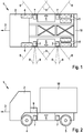
- the device 7 or device 9 for receiving sensor devices is shown in a schematic cross section.
- the housing shell 10 can be seen, which is designed to be open on one side.
- the bottom and the side walls of the housing shell 10 can advantageously be made of a sensor radiation-absorbing material, so that sensor radiation from sensors 15 inside the device 7, 9 does not penetrate outward in undesired directions or penetrates outward only very strongly attenuated.
- the housing shell 10 is closed on the open side by means of a cover 12 made of material that is permeable to sensor radiation.
- the material permeable to the sensor radiation is matched to the wavelength of the sensors 15 located inside, so that the sensor radiation can penetrate the cover 12 of the device 7 in the direction of the main sensor axes 16 of the sensors 15.
- the housing shell 10 can have mounting eyes 11 or fastening eyes 11 with which the device 7, 9 can be fastened to the vehicle 1 or with the aid of a holder for the device 7, 9.
- the device 7, 9 also has connections 13, 14 by means of which the sensors 15 inside the device 7, 9 are connected to a voltage supply 13 and, alternatively or additionally, to a data bus system of the vehicle 1.
- the connection to the voltage supply 13 and the connection to a data bus system 14 are likewise conceivable not to be carried out separately, but rather to be carried out by means of a single, multi-core cable or cable harness.
- each sensor 15 in the interior of the device 7, 9 to have its own, that is to say separate, voltage supply 13 and / or a separate connection to the data bus system 14.
- each sensor 15 it is also possible within the scope of the invention for each sensor 15 to have its own, that is to say separate, connection, this connection in each case consisting of a combination of voltage supply and data bus connection.
- the sensor arrangement is off Figure 3 pictured in a similar manner.
- the housing shell 10 with the mounting eyelets 11 and the cover 12, which closes the housing shell 10 and is mounted in the detection direction of the sensors 15 arranged inside, can again be seen.
- the sensors 15 are shown, which can emit and receive sensor radiation in the direction of the main sensor axes 16.
- the device 7, 9 shown has connections to a voltage supply 13 and / or to a data bus system 14.
- absorbers 17 are also drawn in, which are made of a material which can attenuate the wavelength used by the sensors 15 particularly well, for example by the electromagnetic radiation of this wavelength range being absorbed as completely as possible.
- the absorbers 17 shown here are suitable for avoiding unwanted reflections in the interior of the device 7, 9, preventing radiation in directions other than the desired directions of the main beam directions 16 and, if possible, crosstalk or interference between the sensors 15 within a device 7, 9 prevent.
- the sensors 15 in the interior of the device 7, 9 are fixedly mounted, preferably by being fixedly fixed to the housing shell 10 by means of fastening devices.
- the absorbers 17 can be designed in such a way that they are adapted to the respective arrangement of the sensors 15 in the interior of the device 7, 9.
Landscapes
- Engineering & Computer Science (AREA)
- Remote Sensing (AREA)
- Radar, Positioning & Navigation (AREA)
- Physics & Mathematics (AREA)
- Computer Networks & Wireless Communication (AREA)
- General Physics & Mathematics (AREA)
- Computer Security & Cryptography (AREA)
- Electromagnetism (AREA)
- Signal Processing (AREA)
- Mechanical Engineering (AREA)
- Human Computer Interaction (AREA)
- Optical Radar Systems And Details Thereof (AREA)
- Body Structure For Vehicles (AREA)
Abstract
Description
- Die vorliegende Erfindung betrifft eine Vorrichtung für ein Fahrzeug, die an einem Fahrzeug, insbesondere einem Nutzfahrzeug, befestigt ist und in der mindestens ein oder mehrere Umfeldsensoren befestigt sind, wobei eine Gehäusewand der Vorrichtung, vorzugsweise die Wand in Richtung des Erfassungsbereichs der Umfeldsensoren, aus einem sensorstrahlungsdurchlässigen Material gefertigt ist und mindestens eine Gehäusewand der Vorrichtung, vorzugsweise die Wand, die in entgegengesetzter Richtung zum Erfassungsbereich der Umfeldsensoren orientiert ist, aus einem sensorstrahlungsabsorbierenden Material gefertigt ist.
- Aus der
DE 10 2010 034 073 A1 ist eine Vorrichtung zur Montage einer Sensorbaugruppe an einem Kraftfahrzeug bekannt, die sich insbesondere an einem Stoßfänger des Kraftfahrzeugs befindet und zwischen der Sensorbaugruppe und dem KFZ-Anbauteil ein Formteil aufweist, das massiv ausgebildet ist und für Sensorsignale durchlässig ausgebildet ist. Das Formteil umschließt die Sensorbaugruppe dabei formschlüssig und weist eine Oberfläche auf, die komplementär zur Oberfläche des KFZ-Anbauteils geformt ist. - Eine derartige Integration eines Sensors in eine Stoßstange eines Fahrzeugs ist lediglich zur Positionierung von Sensoren an der Vorderseite und Rückseite des Fahrzeugs möglich. Weitere Montagepositionen, insbesondere seitlich am Fahrzeug, sind hierdurch nicht sinnvoll herstellbar. Weiterhin ist die Integration von Sensoren in Karosserieteilen des Fahrzeugs gemäß dem bekannten Stand der Technik nicht geeignet bei Fahrzeugen, die keine Karosseriebauteile rings um das Fahrzeug herum aufweisen, wie es beispielsweise bei Nutzfahrzeugen der Fall ist.
- Der Kern der vorliegenden Erfindung ist es, eine Vorrichtung anzugeben, in der ein oder mehrere Umfeldsensoren untergebracht werden können und die in Richtung der Erfassungsbereiche der Umfeldsensoren sensortransparente Eigenschaften aufweist. In entgegengesetzter Richtung, insbesondere auch in allen anderen Richtungen, die nicht der Richtung des Erfassungsbereichs entsprechen, können dabei vorteilhafter Weise strahlunsabsorbierend ausgeführt sein. Dabei kann die Vorrichtung vorteilhafter Weise an tragenden Kraftfahrzeugteilen, beispielsweise einem Fahrzeugleiterrahmen montiert werden.
- Erfindungsgemäß wird dieses durch die Merkmale des unabhängigen Anspruchs erreicht. Vorteilhafte Weiterbildungen und Ausgestaltungen ergeben sich aus den Unteransprüchen.
- Vorteilhafter Weise ist vorgesehen, dass die Vorrichtung eine gemeinsame Spannungsversorgung und/oder eine gemeinsame Anbindung an mindestens ein Datenbussystem des Fahrzeugs aufweist. Dabei kann diese gemeinsame Spannungsversorgung die Spannungsversorgung sämtlicher, in der Vorrichtung untergebrachter Sensoren, übernehmen. Zusätzlich oder alternativ kann die Datenbusanbindung alle in der Vorrichtung untergebrachten Sensoren an ein Kraftfahrzeugbussystem anbinden und den Datenaustausch mit anderen Fahrzeugsystemen ermöglichen. Weiterhin ist denkbar, dass sowohl die Spannungsversorgung als auch die Datenbusanbindung aller Sensoren über ein einzelnes, mehradriges Kabel oder einen Kabelbaum erfolgt. Hierdurch ist es möglich, dass nicht für jeden Sensor eine eigene Spannungsversorgung und ein eigener Datenbusanschluss realisiert werden muss, wodurch sich der Verkabelungsaufwand reduziert. Das Datenbussystem kann ein Datentransfersystem sein, eine Datenschnittstelle sein oder ein Datenkommunikationssystem sein.
- Weiterhin ist es vorteilhaft, dass die Umfeldsensoren Radarsensoren sind. Radarsensoren sind heute sehr klein und sehr kostengünstig herstellbar und sind geeignet, das Fahrzeugumfeld zu überwachen und den Fahrer zu informieren, falls Verkehrsteilnehmer wie Fahrradfahrer in gefährlichen Bereichen detektiert werden, beispielsweise im toten Winkel wenn das Fahrzeug abbiegen möchte. Radarsensoren bieten hierbei den Vorteil, dass sie sehr scharf abgegrenzte Erfassungsbereiche haben können und damit zuverlässig Verkehrsteilnehmer in speziellen Umfeldbereichen des Fahrzeugs detektieren können.
- Weiterhin ist es vorteilhaft, dass im inneren der Vorrichtung Absorber zur Absorption eines Teils der Sensorstrahlung angebracht sind. Dabei können Absorber vorgesehen sein, die beispielsweise als Schaumstoff ausgeführt sind und absorbierende Eigenschaften für elektromagnetische Strahlen aufweisen, beispielsweise indem Metallpartikel in den Schaumstoff eingearbeitet sind. Wahlweise kann zusätzlich oder alternativ auch Kunststoff mit Kohleanteil verwendet werden, wie es beispielsweise unter der Bezeichnung Cawiton® von auf dem Markt angeboten wird. Derartige oder ähnliche Absorber können an den Innenseiten der nicht strahlungsdurchlässigen Vorrichtungswände angebracht sein, um unerwünschte Reflexionen zu reduzieren. Zusätzlich oder alternativ können auch zwischen den einzelnen Sensoren innerhalb der Vorrichtung Absorber vorgesehen sein, so dass sich die Sensoren untereinander mit ihrer abgestrahlten und empfangenen Leistung nicht beeinträchtigen. Anstatt Absorbern können auch Reflektoren verwendet werden, wobei es möglich ist, nur Reflektoren einzusetzen oder Absorber und Reflektoren beliebig miteinander zu kombinieren. Je nach Erfordernis hinsichtlich der Ausleuchtung der erwünschten Detektionsbereiche und der sich dabei ergebeneden Reflexionen können Absorber und Reflektoren auch gemischt verbaut werden. Die Reflektoren könne dabei aus Metall gefertigt sein oder aus metallbeschichtetem Kunststoff bestehen und so ausgeführt und montiert sein, dass störende elektromagnetische Strahlung in Raumrichtungen reflektiert werden, in denen der Sensor weder detektieren möchte noch andere Sensoren oder Geräte angebracht sind und gestört werden. Damit werden die störenden elektromagnetische Strahlen in Raumrichtungen wegreflektiert, in denen keine Störungen zu erwarten sind.
- Weiterhin ist es vorteilhaft, dass die Umfeldsensoren Lidarsensoren und/oder Videosensoren sind. Dabei kann das sensorstrahlungsdurchlässige Material der Vorrichtung, das in Richtung des Sensorerfassungsbereichs orientiert ist, für die optische Sensorstrahlung, beispielsweise für Infrarotstrahlung durchlässig sein. Hierdurch ist es möglich, dass Infrarotkameras, die Objekte im Fahrzeugumfeld detektieren können, geschützt sind und für den Beobachter unsichtbar und optisch ansprechend verbaut sind.
- Weiterhin ist es vorteilhaft, dass die Umfeldsensoren für die Überwachung des Vorhandenseins von Objekten im toten Winkel des Fahrzeugs vorgesehen sind. Dabei können die Umfeldsensoren Sensorerfassungsbereiche haben, die so ausgerichtet sind, dass Objekte im toten Winkel des Fahrzeugs erfasst werden. Derartige Vorrichtungen können insbesondere so angeordnet sein, dass deren Erfassungsbereich einen toten Winkel des Fahrzeugs, also einen Bereich des Fahrzeugumfelds, das durch den Fahrer nicht einsehbar ist, überwacht werden.
- Weiterhin ist es vorteilhaft, dass die Vorrichtung am Fahrzeug im Bereich zwischen der Vorderachse und der Hinterachse angebracht ist. Bei Fahrzeugen mit mehreren Hinterachsen ist es vorteilhaft, dass die Vorrichtung im Bereich zwischen der Vorderachse und der vordersten Hinterachse angebracht ist. Bei Nutzfahrzeugen in Leiterrahmenbauweise bietet der Bereich zwischen Vorderachse und der vordersten Hinterachse vielfältige Montagemöglichkeiten, wobei in diesem Bereich bereits Vorrichtungen wie Kraftstoffbehälter oder Abgaseinrichtungen verbaut sein können. Dabei ist zu beachten, dass die Vorrichtung so gestaltet ist, dass diese am Rahmen des Fahrzeugs, also von der seitlichen Fahrzeugsilhouette nach innen zurückspringt und damit die Vorrichtung in ihrer Dimensionierung so gestaltet ist, dass die Außenseite der Vorrichtung mit der Fahrzeugsilhouette abschließt. Daher ist es auch besonders vorteilhaft, die Vorrichtung benachbart zum Kraftstofftank des Fahrzeugs oder zu Abgaseinrichtungen des Fahrzeugs anzubringen. Weiterhin ist es vorteilhaft, dass die Vorrichtung oberhalb des Kraftstofftanks, insbesondere zwischen der Fahrerkabine und dem Nutzaufbau des Fahrzeugs angebracht ist. Der Nutzaufbau des Fahrzeugs kann beispielsweise eine Ladefläche, ein Kofferaufbau, ein Tankaufbau oder ein sonstiger Aufbau des Fahrzeugs sein, so dass die Vorrichtung zwischen der Vorderkante dieses Nutzaufbaus und der Rückseite der Fahrerkabine untergebracht werden kann. Dabei kann die Vorrichtung so orientiert werden, dass der Erfassungsbereich im Wesentlichen in Fahrzeugquerrichtung, also rechtwinklig zur üblichen Fahrtrichtung des Fahrzeugs, orientiert ist.
- Weiterhin ist es vorteilhaft, dass die Vorrichtung jeweils auf beiden Seiten des Fahrzeugs, insbesondere beidseits paarweise, angebracht sind.
- Es wird darauf hingewiesen, dass einige der Möglichkeiten Merkmale und Vorteile der Erfindung hierin mit Bezug auf unterschiedliche Ausführungsformen beschrieben sind. Ein Fachmann erkennt, dass die Merkmale in geeigneter Weise kombiniert, angepasst oder ausgetauscht werden können, um zu weiteren Ausführungsformen der Erfindung zu gelangen.
- Nachfolgend werden Ausführungsbeispiele der Erfindung anhand von Zeichnungen erläutert.
- Es zeigen
- Figur 1
- eine schematische Draufsicht auf die Skizze eines erfindungsgemäßen Fahrzeugs,
- Figur 2
- eine schematische Seitenansicht einer Skizze des erfindungsgemäßen Fahrzeugs,
- Figur 3
- eine Skizze eines Querschnitts durch die erfindungsgemäße Vorrichtung und
- Figur 4
- eine weitere Skizze eines Querschnitts durch die erfindungsgemäße Vorrichtung mit Darstellung einer Ausführungsform der Absorber.
- In
Figur 1 ist eine schematische Draufsicht auf ein Fahrzeug 1 gezeigt, das mit der erfindungsgemäßen Vorrichtung 7 für Umfeldsensoren ausgerüstet ist. Dabei handelt es sich bei dem Fahrzeug 1 vorzugsweise um ein Nutzfahrzeug, das so orientiert ist, dass dieses normalerweise in Richtung der Fahrtrichtung 3 nach links orientiert fährt. Dieses Fahrzeug 1 weist im vorderen Bereich die Fahrerkabine 2 auf, in der sich der Fahrer und gegebenenfalls Beifahrer befinden und unterhalb derer meist der Motor eingebaut ist. Weiterhin sind im Bereich der Fahrerkabine 2 die Räder der Vorderachse 4 dargestellt. Im hinteren Bereich des Fahrzeugs 1, also am rechten Rand derFigur 1 , befinden sich die Räder der vordersten Hinterachse, die inFigur 1 als Zwillingsreifen ausgeführt sind. Zwischen den Rädern der Vorderachse 4 und den Rädern der vordersten Hinterachse 5 befinden sich bei Nutzfahrzeugen häufig die Kraftstoffbehälter 6, die ebenfalls schematisch dargestellt sind. Die erfindungsgemäße Vorrichtung 7, die zur Aufnahme von Umfeldsensoren vorgesehen ist, kann dabei mehrfach verbaut werden, beispielsweise direkt hinter den Rädern der Vorderachse oder auch zwischen dem Kraftstofftank 6 und den vordersten Rädern der Hinterachse 5. Die Vorrichtungen 7 sind hierbei als Vorrichtungen ausgeführt, die direkt oder unter Zuhilfenahme einer Haltevorrichtung am Leiterrahmen des Fahrzeugs 1 montiert werden können oder an anderen Komponenten, beispielsweise den Kraftstoffbehälter, befestigbar sind. - Die Vorrichtungen 7 weisen dabei ein oder mehrere Umfeldsensoren auf, die so orientiert sind, dass deren Erfassungsbereiche 8 das Umfeld des Fahrzeugs 1 erfassen. Dabei kann in einer Vorrichtung 7 nur ein einzelner Umfeldsensor verbaut sein, wie es beispielsweise bei den beiden oberen Vorrichtungen 7 in
Figur 1 dargestellt ist oder aber auch mehrere Umfeldsensoren enthalten, so dass jede der Vorrichtungen 7 zwei oder mehr Umfelderfassungsbereiche 8 aufweist, wie in den beiden unteren Vorrichtungen 7 derFigur 1 dargestellt wurde. - In
Figur 2 ist eine schematische Seitenansicht des erfindungsgemäßen Fahrzeugs 1 dargestellt. Dieses ist dabei wieder so orientiert, dass sich dieses üblicherweise in Fahrtrichtung 3 orientiert ist, also bei normaler Geradeausfahrt inFigur 2 nach links fahren würde. Das Fahrzeug 1 weist wieder die Fahrerkabine 2 auf, in der sich Fahrer und Beifahrer befinden und auf dem Motorraum angeordnet ist. Weiterhin sind die Räder der Vorderachse 4 dargestellt, sowie die Räder der vordersten Hinterachse 5, auf denen sich das Fahrzeug 1 fortbewegt. Zwischen den Rädern der Vorderachse 4 und den vordersten Rädern der Hinterachse 5 sind wiederum Komponenten des Fahrzeugs, wie beispielsweise der Kraftstoffbehälter 6, eingezeichnet. Alternativ zum Kraftstoffbehälter 6 ist es ebenfalls möglich, dass Abgaseinrichtungen des Fahrzeugs 1 vorgesehen sind oder Kisten mit Stauraum für Fahrzeugzubehör vorgesehen sind. Weiterhin sind zwischen den Rädern der Vorderachse 4 und den Rädern der vordersten Hinterachse 5 Vorrichtungen 7 dargestellt, die am Fahrzeug oder Fahrzeugkomponenten befestigt sind und ein oder mehrere Fahrzeugumfeldsensoren erfindungsgemäß aufnehmen. Weiterhin ist inFigur 2 ein Nutzaufbau 18 dargestellt, der beispielsweise eine Ladefläche, einen Kofferaufbau oder andere Nutzaufbauten des Fahrzeugs darstellt, je nachdem für welche Aufgabe das Fahrzeug vorgesehen ist. Zwischen der Fahrerkabine 2 und dem Nutzaufbau 18 des Fahrzeugs ergibt sich meist ein Zwischenraum, indem sich erfindungsgemäß eine Vorrichtung für Umfeldsensoren 9 anbringen lässt, die beispielsweise die Bereiche seitlich neben dem Fahrzeug 1 hinsichtlich weiterer Verkehrsteilnehmer überwacht und den Fahrer warnen kann. - In
Figur 3 ist die Vorrichtung 7 bzw. Vorrichtung 9 zur Aufnahme von Sensoreinrichtungen in einem schematischen Querschnitt dargestellt. Zu erkennen ist die Gehäuseschale 10, die nach einer Seite offen ausgeführt ist. Dabei kann der Boden sowie die Seitenwände der Gehäuseschale 10 vorteilhafter Weise aus einem sensorstrahlungsabsorbierenden Material hergestellt sein, so dass Sensorstrahlung von Sensoren 15 im Inneren der Vorrichtung 7, 9 in unerwünschte Richtungen nicht nach außen dringt oder nur sehr stark gedämpft nach außen dringt. Die Gehäuseschale 10 ist an der offenen Seite mittels eines Deckels 12 aus sensorstrahlungsdurchlässigem Material verschlossen. Dabei ist das sensorstrahlungsdurchlässige Material auf die Wellenlänge der im inneren befindlichen Sensoren 15 abgestimmt, so dass die Sensorstrahlung in Richtung der Sensorhauptachsen 16 der Sensoren 15 den Deckel 12 der Vorrichtung 7 durchdringen können. Die Gehäuseschale 10 kann dabei Montageösen 11 oder Befestigungsösen 11 aufweisen, mit denen die Vorrichtung 7, 9 am Fahrzeug 1 oder unter Zuhilfenahme eines Halters für die Vorrichtung 7, 9 befestigt werden kann. Weiterhin weist die Vorrichtung 7, 9 Anschlüsse 13, 14 auf, mittels denen die Sensoren 15 im Inneren der Vorrichtung 7, 9 an eine Spannungsversorgung 13 sowie alternativ oder zusätzlich an ein ein Datenbussystem des Fahrzeugs 1 angeschlossen sind.
Ebenfalls denkbar ist die Anbindung an die Spannungsversorgung 13 und die Anbindung an ein Datenbussystem 14 nicht separat auszuführen, sondern mittels eines einzelnen, mehradrigen Kabels oder Kabelbaumes auszuführen. Weiterhin ist es möglich, dass jeder Sensor 15 im Inneren der Vorrichtung 7, 9 eine eigene, also separate Spannungsversorgung 13 und/oder eine separate Anbindung an das Datenbussystem 14 aufweist. Alternativ ist es im Rahmen der Erfindung weiterhin möglich, dass jeder Sensor 15 einen eigenen, sprich separaten Anschluß aufweist, wobei dieser Anschluß jeweils aus einer Kombination aus Spannungsversorgung und Datenbusanbindung besteht. - In
Figur 4 ist die Sensoranordnung ausFigur 3 in ähnlicher Weise abgebildet. Zu erkennen ist wiederum die Gehäuseschale 10 mit den Montageösen 11 und dem Deckel 12, der die Gehäuseschale 10 abschließt und in Erfassungsrichtung der im Inneren angeordneten Sensoren 15 montiert ist. Im Inneren der Vorrichtung 7, 9 sind die Sensoren 15 dargestellt, die Sensorstrahlung in Richtung der Sensorhauptachsen 16 abstrahlen und empfangen können. Selbstverständlich weist auch die inFigur 4 dargestellte Vorrichtung 7, 9 Anschlüsse an eine Spannungsversorgung 13 und/oder an ein Datenbussystem 14 auf. InFigur 4 sind weiterhin Absorber 17 eingezeichnet, die aus einem Material herstellt sind, das die von den Sensoren 15 verwendete Wellenlänge besonders gut dämpfen kann, beispielsweise indem die elektromagnetische Strahlung dieses Wellenlängenbereichs möglichst vollständig absorbiert wird.
Diese inFigur 4 dargestellten Absorber 17 sind dabei geeignet, unerwünschte Reflexionen im Inneren der Vorrichtung 7, 9 zu vermeiden, Abstrahlungen in andere Richtungen als in den gewünschten Richtungen der Hauptstrahlrichtungen 16 zu unterbinden sowie ein Übersprechen oder Stören zwischen den Sensoren 15 innerhalb einer Vorrichtung 7, 9 möglichst zu unterbinden. Die Sensoren 15 im Inneren der Vorrichtung 7, 9 sind dabei fest montiert, vorzugsweise indem diese fest an der Gehäuseschale 10 mittels Befestigungsvorrichtungen fixiert sind. Dabei können die Absorber 17 so gestaltet sein, dass diese auf die jeweilige Anordnung der Sensoren 15 im Inneren der Vorrichtung 7, 9 angepasst sind.
Claims (10)
- Vorrichtung (7), die an einem Fahrzeug (1), insbesondere einem Nutzfahrzeug, befestigt ist
dadurch gekennzeichnet, dass
in der Vorrichtung (7) mindestens ein oder mehrere Umfeldsensoren (15) befestigt sind,
und eine Gehäusewand (12) der Vorrichtung (7), vorzugsweise die Wand in Richtung des Erfassungsbereichs (8, 16) der Umfeldsensoren (15), aus einem sensorstrahlungsdurchlässigen Material gefertigt ist und mindestens eine Gehäusewand (10) der Vorrichtung (7), vorzugsweise die Wand in entgegengesetzter Richtung zum Erfassungsbereich (8, 16) der Umfeldsensoren (15), aus einem sensorstrahlungsabsorbierenden Material gefertigt ist. - Vorrichtung nach Anspruch 1, dadurch gekennzeichnet, dass die Umfeldsensoren (15) in der Vorrichtung (7) eine gemeinsame Spannungsversorgung (13) und/oder eine gemeinsame Anbindung an mindestens ein Datenbussystem (14) des Fahrzeugs (1) haben.
- Vorrichtung nach Anspruch 1 oder 2, dadurch gekennzeichnet, dass die Umfeldsensoren (15) Radarsensoren sind.
- Vorrichtung nach einem der Ansprüche 1 bis 3, dadurch gekennzeichnet, dass im Inneren der Vorrichtung (7) Absorber (17) zur Absorption eines teils der Sensorstrahlung angebracht sind.
- Vorrichtung nach einem der Ansprüche 1 bis 4, dadurch gekennzeichnet, dass die Umfeldsensoren (15) Lidarsensoren und/oder Videosensoren sind.
- Vorrichtung nach einem der Ansprüche 1 bis 5, dadurch gekennzeichnet, dass die Umfeldsensoren (15) für die Überwachung des Vorhandenseins von Objekten im Toten Winkel des Fahrzeugs (1) vorgesehen sind und einen Sensorerfassungsbereich (8) haben und so ausgerichtet sind, dass Objekte im Tote Winkel des Fahrzeugs (1) erfasst werden.
- Vorrichtung nach einem der Ansprüche 1 bis 6, dadurch gekennzeichnet, dass die Vorrichtung (7) am Fahrzeug (1) im Bereich zwischen der Vorderachse (4) und der vordersten Hinterachse (5) angebracht ist.
- Vorrichtung nach einem der Ansprüche 1 bis 7, dadurch gekennzeichnet, dass die Vorrichtung (7) benachbart zum Kraftstofftank (6) des Fahrzeugs (1) angebracht ist.
- Vorrichtung nach einem der Ansprüche 1 bis 6, dadurch gekennzeichnet, dass die Vorrichtung (7) oberhalb des Kraftstofftanks (6), insbesondere zwischen der Fahrerkabine (2) und dem Nutzaufbau (18) des Fahrzeugs (1), angebracht ist.
- Vorrichtung nach einem der vorhergehenden Ansprüche, dadurch gekennzeichnet, dass die Vorrichtung (7) jeweils auf beiden Seiten des Fahrzeugs (1), insbesondere beidseits paarweise, angebracht sind.
Applications Claiming Priority (1)
| Application Number | Priority Date | Filing Date | Title |
|---|---|---|---|
| DE102019213170.0A DE102019213170A1 (de) | 2019-08-30 | 2019-08-30 | Vorrichtung für ein Fahrzeug |
Publications (2)
| Publication Number | Publication Date |
|---|---|
| EP3787108A1 true EP3787108A1 (de) | 2021-03-03 |
| EP3787108B1 EP3787108B1 (de) | 2023-01-25 |
Family
ID=71515043
Family Applications (1)
| Application Number | Title | Priority Date | Filing Date |
|---|---|---|---|
| EP20184172.3A Active EP3787108B1 (de) | 2019-08-30 | 2020-07-06 | Vorrichtung für ein fahrzeug |
Country Status (4)
| Country | Link |
|---|---|
| US (1) | US11402497B2 (de) |
| EP (1) | EP3787108B1 (de) |
| CN (1) | CN112444808A (de) |
| DE (1) | DE102019213170A1 (de) |
Citations (7)
| Publication number | Priority date | Publication date | Assignee | Title |
|---|---|---|---|---|
| US20040036645A1 (en) * | 2002-08-22 | 2004-02-26 | Hitachi, Ltd. | Millimeter wave radar |
| JP2004309275A (ja) * | 2003-04-04 | 2004-11-04 | Matsushita Electric Works Ltd | レーダ装置 |
| JP2007057483A (ja) * | 2005-08-26 | 2007-03-08 | Hitachi Ltd | ミリ波レーダ装置 |
| DE102010034073A1 (de) | 2010-08-12 | 2012-02-16 | Conti Temic Microelectronic Gmbh | Vorrichtung zur Montage einer Sensor-Baugruppe, insbesondere eines Radarsensors |
| US20150123872A1 (en) * | 2012-06-14 | 2015-05-07 | Denso Corporation | Radar apparatus provided with radome |
| US20160370456A1 (en) * | 2015-06-17 | 2016-12-22 | Volvo Car Corporation | Low reflection radar bracket |
| US20170057441A1 (en) * | 2015-08-31 | 2017-03-02 | Flex-N-Gate Corporation | Blind spot monitor arrangement for a vehicle bumper |
Family Cites Families (29)
| Publication number | Priority date | Publication date | Assignee | Title |
|---|---|---|---|---|
| US5493269A (en) * | 1991-09-20 | 1996-02-20 | C.A.R.E., Inc. | Vehicular safety sensor and warning system |
| US7209221B2 (en) * | 1994-05-23 | 2007-04-24 | Automotive Technologies International, Inc. | Method for obtaining and displaying information about objects in a vehicular blind spot |
| US8041483B2 (en) * | 1994-05-23 | 2011-10-18 | Automotive Technologies International, Inc. | Exterior airbag deployment techniques |
| US6400308B1 (en) * | 1998-02-20 | 2002-06-04 | Amerigon Inc. | High performance vehicle radar system |
| US7852462B2 (en) * | 2000-05-08 | 2010-12-14 | Automotive Technologies International, Inc. | Vehicular component control methods based on blind spot monitoring |
| US6489927B2 (en) * | 2000-08-16 | 2002-12-03 | Raytheon Company | System and technique for mounting a radar system on a vehicle |
| JP2004325160A (ja) * | 2003-04-23 | 2004-11-18 | Hitachi Ltd | 車載用レーダ |
| NL1024632C2 (nl) * | 2003-10-27 | 2005-04-28 | Intertruck Benelux B V | Inrichting voor het vermijden van verkeersongelukken waarbij tenminste een auto is betrokken. |
| JPWO2005055366A1 (ja) * | 2003-11-14 | 2007-06-28 | 株式会社日立製作所 | 車載用レーダ |
| JP2006029834A (ja) * | 2004-07-13 | 2006-02-02 | Hitachi Ltd | 車載用レーダ |
| JP2007116217A (ja) * | 2005-10-18 | 2007-05-10 | Hitachi Ltd | ミリ波レーダ装置およびそれを用いたミリ波レーダシステム |
| US8010252B2 (en) * | 2007-10-05 | 2011-08-30 | Ford Global Technologies | Trailer oscillation detection and compensation method for a vehicle and trailer combination |
| JP5558342B2 (ja) * | 2009-02-27 | 2014-07-23 | トヨタ自動車株式会社 | 車載レーダー装置および車載レーダー装置用カバー |
| JP5555087B2 (ja) * | 2010-07-30 | 2014-07-23 | 株式会社豊田中央研究所 | レーダ装置 |
| DE102011122346A1 (de) * | 2011-12-23 | 2013-06-27 | Valeo Schalter Und Sensoren Gmbh | Radareinrichtung für ein Kraftfahrzeug, Halter für ein Radargerät und Verfahren zum Herstellen eines Absorptionselements für ein Radargerät |
| DE102012017669A1 (de) * | 2012-09-07 | 2014-03-13 | Valeo Schalter Und Sensoren Gmbh | Anordnung mit einem Verkleidungsteil und einem Radarsensor, Kraftfahrzeug und Verfahren zum Herstellen einer Anordnung |
| US9097800B1 (en) * | 2012-10-11 | 2015-08-04 | Google Inc. | Solid object detection system using laser and radar sensor fusion |
| JP6365251B2 (ja) * | 2014-02-28 | 2018-08-01 | パナソニック株式会社 | レーダ装置 |
| KR102261329B1 (ko) * | 2015-07-24 | 2021-06-04 | 엘지전자 주식회사 | 안테나, 차량용 레이더, 및 이를 구비하는 차량 |
| DE102016010441A1 (de) * | 2016-08-27 | 2017-02-16 | Daimler Ag | Sensoreinrichtung für einen Kraftwagen, insbesondere für einen Personenkraftwagen |
| EP3315998B1 (de) * | 2016-10-25 | 2021-12-08 | KNORR-BREMSE Systeme für Nutzfahrzeuge GmbH | Vorrichtung und verfahren zur bestimmung der geschwindigkeit eines fahrzeugs |
| JP2018112528A (ja) * | 2017-01-13 | 2018-07-19 | 本田技研工業株式会社 | カバー部材およびセンサーアセンブリ |
| CN206900319U (zh) * | 2017-06-22 | 2018-01-19 | 北汽福田汽车股份有限公司 | 一种汽车及其雷达布置结构 |
| US20190204845A1 (en) * | 2017-12-29 | 2019-07-04 | Waymo Llc | Sensor integration for large autonomous vehicles |
| CA3097517C (en) * | 2018-04-25 | 2023-04-18 | Waymo Llc | Underbody radar units |
| US10336253B1 (en) * | 2018-09-25 | 2019-07-02 | Winwise Tech Co., Ltd. | Vehicle side obstacle detecting and warning method and detecting and warning system of vehicle side obstacle |
| SE542590C2 (en) * | 2018-10-17 | 2020-06-09 | Zuragon Sweden AB | Method and system for calibration of sensor signals in a vehicle |
| EP3664063A1 (de) * | 2018-12-07 | 2020-06-10 | Zenuity AB | Unterfahrzeuginspektion |
| US11391820B2 (en) * | 2019-04-26 | 2022-07-19 | Waymo L LC | Mirrors to extend sensor field of view in self-driving vehicles |
-
2019
- 2019-08-30 DE DE102019213170.0A patent/DE102019213170A1/de not_active Withdrawn
-
2020
- 2020-07-06 EP EP20184172.3A patent/EP3787108B1/de active Active
- 2020-07-30 US US16/943,148 patent/US11402497B2/en active Active
- 2020-08-28 CN CN202010885002.9A patent/CN112444808A/zh active Pending
Patent Citations (7)
| Publication number | Priority date | Publication date | Assignee | Title |
|---|---|---|---|---|
| US20040036645A1 (en) * | 2002-08-22 | 2004-02-26 | Hitachi, Ltd. | Millimeter wave radar |
| JP2004309275A (ja) * | 2003-04-04 | 2004-11-04 | Matsushita Electric Works Ltd | レーダ装置 |
| JP2007057483A (ja) * | 2005-08-26 | 2007-03-08 | Hitachi Ltd | ミリ波レーダ装置 |
| DE102010034073A1 (de) | 2010-08-12 | 2012-02-16 | Conti Temic Microelectronic Gmbh | Vorrichtung zur Montage einer Sensor-Baugruppe, insbesondere eines Radarsensors |
| US20150123872A1 (en) * | 2012-06-14 | 2015-05-07 | Denso Corporation | Radar apparatus provided with radome |
| US20160370456A1 (en) * | 2015-06-17 | 2016-12-22 | Volvo Car Corporation | Low reflection radar bracket |
| US20170057441A1 (en) * | 2015-08-31 | 2017-03-02 | Flex-N-Gate Corporation | Blind spot monitor arrangement for a vehicle bumper |
Non-Patent Citations (2)
| Title |
|---|
| W. RILEY GARROTT ET AL: "Hardware Evaluation of Heavy Truck Side and Rear Object Detection Systems", KONFERENZBEITRAG ''IBEC 2003'' UND SAE TECHNICAL PAPER SERIES 2002-01-20 48, vol. 1, 27 February 1995 (1995-02-27), US, pages 951010, XP055733457, ISSN: 0148-7191, DOI: 10.4271/951010 * |
| WABCO: "BLIND SPOT DETECTION SYSTEM", 1 May 2018 (2018-05-01), XP055733456, Retrieved from the Internet <URL:https://www.wabco-auto.com/WabcoWeb/media/Library/Assets/WABCO-pictures/Documents%20(PDF)/Brochures/OnSide_Sales_Brochure_SP18020.pdf?ext=.pdf> [retrieved on 20200923] * |
Also Published As
| Publication number | Publication date |
|---|---|
| DE102019213170A1 (de) | 2021-03-04 |
| US20210063567A1 (en) | 2021-03-04 |
| CN112444808A (zh) | 2021-03-05 |
| EP3787108B1 (de) | 2023-01-25 |
| US11402497B2 (en) | 2022-08-02 |
Similar Documents
| Publication | Publication Date | Title |
|---|---|---|
| EP3510463B1 (de) | Sensoranordnung für ein autonom betriebenes nutzfahrzeug und ein verfahren zur rundumbilderfassung | |
| DE102016104871B4 (de) | Struktur zur Unterbringung eines Umgebungsinformationserfassungssensors, sowie selbstfahrendes Fahrzeug | |
| EP3387462B1 (de) | Kraftfahrzeug mit in einer aussenwandung eingebauten sensoreinrichtung | |
| DE102016216251B4 (de) | Kraftfahrzeug zur Nutzung im Straßenverkehr und Verfahren zur Ermittlung einer Ausdehnung eines Fremdfahrzeugs in einem Kraftfahrzeug | |
| DE2937904A1 (de) | Rueckwaertiger karosserieaufbau eines fahrzeugs | |
| DE102011102773A1 (de) | Kamerasystem für ein Kraftfahrzeug | |
| DE102016102904A1 (de) | Fahrzeugkamerasystem, Objektivmodul eines Fahrzeugkamerasystems und Verfahren zur Herstellung eines Fahrzeugkamerasystems | |
| DE102012010876A1 (de) | Fahrzeug und Verfahren zur Unterstützung eines Fahrers beim Führen eines Fahrzeugs | |
| DE102018121211A1 (de) | Fahrerhausfrontmodul und Verfahren zur Herstellung eines Fahrerhauses | |
| DE2839849A1 (de) | Kraftfahrzeug | |
| EP3787108B1 (de) | Vorrichtung für ein fahrzeug | |
| DE102021131893B4 (de) | Hintere fahrzeugkörper-verbindungsstruktur | |
| DE102019204418B3 (de) | Kameraarmvorrichtung für ein Spiegelersatzsystem für ein Kraftfahrzeug und Kraftfahrzeug | |
| DE102021115334A1 (de) | Dachmodul zur Bildung eines Fahrzeugdachs mit einem Sensormodul | |
| EP3272589B1 (de) | Scharnierabdeckung eines nutzfahrzeugs zur aufnahme einer bilderfassungseinheit | |
| DE102018116878A1 (de) | Vordere Fahrzeugkarosserieverstärkungsstruktur | |
| DE102005038808A1 (de) | Anordnung eines Emblems am Ende eines Kraftwagens | |
| DE8712103U1 (de) | Steckdosenhalter für Kraftfahrzeuge | |
| DE102022200782A1 (de) | Außenrückblickanordnung für Straßenfahrzeuge und Verfahren zur Herstellung einer Außenrückblickanordnung für Straßenfahrzeuge | |
| DE102017208809B4 (de) | Lastenträger für Fahrzeuge und Fahrzeug mit einem Lastenträger | |
| DE102012002582A1 (de) | Monitor für Kraftfahrzeug | |
| DE102009039302A1 (de) | Anbauteil für Kraftfahrzeuge mit einer Kamera zur Überwachung der seitlichen Sichtfelder | |
| DE20108148U1 (de) | Blinker für Kraftfahrzeuge | |
| DE102008009870A1 (de) | Stauvorrichtung in einem Kraftfahrzeug | |
| DE102022208282A1 (de) | Multifunktionales Sensorcrashcase |
Legal Events
| Date | Code | Title | Description |
|---|---|---|---|
| PUAI | Public reference made under article 153(3) epc to a published international application that has entered the european phase |
Free format text: ORIGINAL CODE: 0009012 |
|
| STAA | Information on the status of an ep patent application or granted ep patent |
Free format text: STATUS: THE APPLICATION HAS BEEN PUBLISHED |
|
| AK | Designated contracting states |
Kind code of ref document: A1 Designated state(s): AL AT BE BG CH CY CZ DE DK EE ES FI FR GB GR HR HU IE IS IT LI LT LU LV MC MK MT NL NO PL PT RO RS SE SI SK SM TR |
|
| AX | Request for extension of the european patent |
Extension state: BA ME |
|
| STAA | Information on the status of an ep patent application or granted ep patent |
Free format text: STATUS: REQUEST FOR EXAMINATION WAS MADE |
|
| 17P | Request for examination filed |
Effective date: 20210903 |
|
| RBV | Designated contracting states (corrected) |
Designated state(s): AL AT BE BG CH CY CZ DE DK EE ES FI FR GB GR HR HU IE IS IT LI LT LU LV MC MK MT NL NO PL PT RO RS SE SI SK SM TR |
|
| STAA | Information on the status of an ep patent application or granted ep patent |
Free format text: STATUS: EXAMINATION IS IN PROGRESS |
|
| 17Q | First examination report despatched |
Effective date: 20220118 |
|
| GRAP | Despatch of communication of intention to grant a patent |
Free format text: ORIGINAL CODE: EPIDOSNIGR1 |
|
| STAA | Information on the status of an ep patent application or granted ep patent |
Free format text: STATUS: GRANT OF PATENT IS INTENDED |
|
| INTG | Intention to grant announced |
Effective date: 20221114 |
|
| GRAS | Grant fee paid |
Free format text: ORIGINAL CODE: EPIDOSNIGR3 |
|
| GRAA | (expected) grant |
Free format text: ORIGINAL CODE: 0009210 |
|
| STAA | Information on the status of an ep patent application or granted ep patent |
Free format text: STATUS: THE PATENT HAS BEEN GRANTED |
|
| AK | Designated contracting states |
Kind code of ref document: B1 Designated state(s): AL AT BE BG CH CY CZ DE DK EE ES FI FR GB GR HR HU IE IS IT LI LT LU LV MC MK MT NL NO PL PT RO RS SE SI SK SM TR |
|
| REG | Reference to a national code |
Ref country code: GB Ref legal event code: FG4D Free format text: NOT ENGLISH |
|
| REG | Reference to a national code |
Ref country code: CH Ref legal event code: EP |
|
| REG | Reference to a national code |
Ref country code: AT Ref legal event code: REF Ref document number: 1546464 Country of ref document: AT Kind code of ref document: T Effective date: 20230215 Ref country code: IE Ref legal event code: FG4D Free format text: LANGUAGE OF EP DOCUMENT: GERMAN |
|
| REG | Reference to a national code |
Ref country code: DE Ref legal event code: R096 Ref document number: 502020002433 Country of ref document: DE |
|
| REG | Reference to a national code |
Ref country code: LT Ref legal event code: MG9D |
|
| REG | Reference to a national code |
Ref country code: NL Ref legal event code: MP Effective date: 20230125 |
|
| PG25 | Lapsed in a contracting state [announced via postgrant information from national office to epo] |
Ref country code: NL Free format text: LAPSE BECAUSE OF FAILURE TO SUBMIT A TRANSLATION OF THE DESCRIPTION OR TO PAY THE FEE WITHIN THE PRESCRIBED TIME-LIMIT Effective date: 20230125 |
|
| PG25 | Lapsed in a contracting state [announced via postgrant information from national office to epo] |
Ref country code: RS Free format text: LAPSE BECAUSE OF FAILURE TO SUBMIT A TRANSLATION OF THE DESCRIPTION OR TO PAY THE FEE WITHIN THE PRESCRIBED TIME-LIMIT Effective date: 20230125 Ref country code: PT Free format text: LAPSE BECAUSE OF FAILURE TO SUBMIT A TRANSLATION OF THE DESCRIPTION OR TO PAY THE FEE WITHIN THE PRESCRIBED TIME-LIMIT Effective date: 20230525 Ref country code: NO Free format text: LAPSE BECAUSE OF FAILURE TO SUBMIT A TRANSLATION OF THE DESCRIPTION OR TO PAY THE FEE WITHIN THE PRESCRIBED TIME-LIMIT Effective date: 20230425 Ref country code: LV Free format text: LAPSE BECAUSE OF FAILURE TO SUBMIT A TRANSLATION OF THE DESCRIPTION OR TO PAY THE FEE WITHIN THE PRESCRIBED TIME-LIMIT Effective date: 20230125 Ref country code: LT Free format text: LAPSE BECAUSE OF FAILURE TO SUBMIT A TRANSLATION OF THE DESCRIPTION OR TO PAY THE FEE WITHIN THE PRESCRIBED TIME-LIMIT Effective date: 20230125 Ref country code: HR Free format text: LAPSE BECAUSE OF FAILURE TO SUBMIT A TRANSLATION OF THE DESCRIPTION OR TO PAY THE FEE WITHIN THE PRESCRIBED TIME-LIMIT Effective date: 20230125 Ref country code: ES Free format text: LAPSE BECAUSE OF FAILURE TO SUBMIT A TRANSLATION OF THE DESCRIPTION OR TO PAY THE FEE WITHIN THE PRESCRIBED TIME-LIMIT Effective date: 20230125 |
|
| PG25 | Lapsed in a contracting state [announced via postgrant information from national office to epo] |
Ref country code: SE Free format text: LAPSE BECAUSE OF FAILURE TO SUBMIT A TRANSLATION OF THE DESCRIPTION OR TO PAY THE FEE WITHIN THE PRESCRIBED TIME-LIMIT Effective date: 20230125 Ref country code: PL Free format text: LAPSE BECAUSE OF FAILURE TO SUBMIT A TRANSLATION OF THE DESCRIPTION OR TO PAY THE FEE WITHIN THE PRESCRIBED TIME-LIMIT Effective date: 20230125 Ref country code: IS Free format text: LAPSE BECAUSE OF FAILURE TO SUBMIT A TRANSLATION OF THE DESCRIPTION OR TO PAY THE FEE WITHIN THE PRESCRIBED TIME-LIMIT Effective date: 20230525 Ref country code: GR Free format text: LAPSE BECAUSE OF FAILURE TO SUBMIT A TRANSLATION OF THE DESCRIPTION OR TO PAY THE FEE WITHIN THE PRESCRIBED TIME-LIMIT Effective date: 20230426 Ref country code: FI Free format text: LAPSE BECAUSE OF FAILURE TO SUBMIT A TRANSLATION OF THE DESCRIPTION OR TO PAY THE FEE WITHIN THE PRESCRIBED TIME-LIMIT Effective date: 20230125 |
|
| REG | Reference to a national code |
Ref country code: DE Ref legal event code: R097 Ref document number: 502020002433 Country of ref document: DE |
|
| PG25 | Lapsed in a contracting state [announced via postgrant information from national office to epo] |
Ref country code: SM Free format text: LAPSE BECAUSE OF FAILURE TO SUBMIT A TRANSLATION OF THE DESCRIPTION OR TO PAY THE FEE WITHIN THE PRESCRIBED TIME-LIMIT Effective date: 20230125 Ref country code: RO Free format text: LAPSE BECAUSE OF FAILURE TO SUBMIT A TRANSLATION OF THE DESCRIPTION OR TO PAY THE FEE WITHIN THE PRESCRIBED TIME-LIMIT Effective date: 20230125 Ref country code: EE Free format text: LAPSE BECAUSE OF FAILURE TO SUBMIT A TRANSLATION OF THE DESCRIPTION OR TO PAY THE FEE WITHIN THE PRESCRIBED TIME-LIMIT Effective date: 20230125 Ref country code: DK Free format text: LAPSE BECAUSE OF FAILURE TO SUBMIT A TRANSLATION OF THE DESCRIPTION OR TO PAY THE FEE WITHIN THE PRESCRIBED TIME-LIMIT Effective date: 20230125 Ref country code: CZ Free format text: LAPSE BECAUSE OF FAILURE TO SUBMIT A TRANSLATION OF THE DESCRIPTION OR TO PAY THE FEE WITHIN THE PRESCRIBED TIME-LIMIT Effective date: 20230125 |
|
| PG25 | Lapsed in a contracting state [announced via postgrant information from national office to epo] |
Ref country code: SK Free format text: LAPSE BECAUSE OF FAILURE TO SUBMIT A TRANSLATION OF THE DESCRIPTION OR TO PAY THE FEE WITHIN THE PRESCRIBED TIME-LIMIT Effective date: 20230125 |
|
| PLBE | No opposition filed within time limit |
Free format text: ORIGINAL CODE: 0009261 |
|
| STAA | Information on the status of an ep patent application or granted ep patent |
Free format text: STATUS: NO OPPOSITION FILED WITHIN TIME LIMIT |
|
| 26N | No opposition filed |
Effective date: 20231026 |
|
| PG25 | Lapsed in a contracting state [announced via postgrant information from national office to epo] |
Ref country code: SI Free format text: LAPSE BECAUSE OF FAILURE TO SUBMIT A TRANSLATION OF THE DESCRIPTION OR TO PAY THE FEE WITHIN THE PRESCRIBED TIME-LIMIT Effective date: 20230125 |
|
| PG25 | Lapsed in a contracting state [announced via postgrant information from national office to epo] |
Ref country code: MC Free format text: LAPSE BECAUSE OF FAILURE TO SUBMIT A TRANSLATION OF THE DESCRIPTION OR TO PAY THE FEE WITHIN THE PRESCRIBED TIME-LIMIT Effective date: 20230125 |
|
| PG25 | Lapsed in a contracting state [announced via postgrant information from national office to epo] |
Ref country code: MC Free format text: LAPSE BECAUSE OF FAILURE TO SUBMIT A TRANSLATION OF THE DESCRIPTION OR TO PAY THE FEE WITHIN THE PRESCRIBED TIME-LIMIT Effective date: 20230125 |
|
| REG | Reference to a national code |
Ref country code: CH Ref legal event code: PL |
|
| REG | Reference to a national code |
Ref country code: BE Ref legal event code: MM Effective date: 20230731 |
|
| PG25 | Lapsed in a contracting state [announced via postgrant information from national office to epo] |
Ref country code: LU Free format text: LAPSE BECAUSE OF NON-PAYMENT OF DUE FEES Effective date: 20230706 |
|
| PG25 | Lapsed in a contracting state [announced via postgrant information from national office to epo] |
Ref country code: LU Free format text: LAPSE BECAUSE OF NON-PAYMENT OF DUE FEES Effective date: 20230706 |
|
| REG | Reference to a national code |
Ref country code: IE Ref legal event code: MM4A |
|
| PG25 | Lapsed in a contracting state [announced via postgrant information from national office to epo] |
Ref country code: CH Free format text: LAPSE BECAUSE OF NON-PAYMENT OF DUE FEES Effective date: 20230731 |
|
| PG25 | Lapsed in a contracting state [announced via postgrant information from national office to epo] |
Ref country code: IT Free format text: LAPSE BECAUSE OF FAILURE TO SUBMIT A TRANSLATION OF THE DESCRIPTION OR TO PAY THE FEE WITHIN THE PRESCRIBED TIME-LIMIT Effective date: 20230125 Ref country code: BE Free format text: LAPSE BECAUSE OF NON-PAYMENT OF DUE FEES Effective date: 20230731 |
|
| PG25 | Lapsed in a contracting state [announced via postgrant information from national office to epo] |
Ref country code: IE Free format text: LAPSE BECAUSE OF NON-PAYMENT OF DUE FEES Effective date: 20230706 |
|
| PG25 | Lapsed in a contracting state [announced via postgrant information from national office to epo] |
Ref country code: IE Free format text: LAPSE BECAUSE OF NON-PAYMENT OF DUE FEES Effective date: 20230706 |
|
| PG25 | Lapsed in a contracting state [announced via postgrant information from national office to epo] |
Ref country code: BG Free format text: LAPSE BECAUSE OF FAILURE TO SUBMIT A TRANSLATION OF THE DESCRIPTION OR TO PAY THE FEE WITHIN THE PRESCRIBED TIME-LIMIT Effective date: 20230125 |
|
| PG25 | Lapsed in a contracting state [announced via postgrant information from national office to epo] |
Ref country code: BG Free format text: LAPSE BECAUSE OF FAILURE TO SUBMIT A TRANSLATION OF THE DESCRIPTION OR TO PAY THE FEE WITHIN THE PRESCRIBED TIME-LIMIT Effective date: 20230125 |
|
| PG25 | Lapsed in a contracting state [announced via postgrant information from national office to epo] |
Ref country code: CY Free format text: LAPSE BECAUSE OF FAILURE TO SUBMIT A TRANSLATION OF THE DESCRIPTION OR TO PAY THE FEE WITHIN THE PRESCRIBED TIME-LIMIT; INVALID AB INITIO Effective date: 20200706 |
|
| PG25 | Lapsed in a contracting state [announced via postgrant information from national office to epo] |
Ref country code: HU Free format text: LAPSE BECAUSE OF FAILURE TO SUBMIT A TRANSLATION OF THE DESCRIPTION OR TO PAY THE FEE WITHIN THE PRESCRIBED TIME-LIMIT; INVALID AB INITIO Effective date: 20200706 |
|
| PGFP | Annual fee paid to national office [announced via postgrant information from national office to epo] |
Ref country code: DE Payment date: 20250924 Year of fee payment: 6 |
|
| PGFP | Annual fee paid to national office [announced via postgrant information from national office to epo] |
Ref country code: GB Payment date: 20250724 Year of fee payment: 6 |
|
| PGFP | Annual fee paid to national office [announced via postgrant information from national office to epo] |
Ref country code: FR Payment date: 20250723 Year of fee payment: 6 Ref country code: AT Payment date: 20251020 Year of fee payment: 5 |
|
| PG25 | Lapsed in a contracting state [announced via postgrant information from national office to epo] |
Ref country code: TR Free format text: LAPSE BECAUSE OF FAILURE TO SUBMIT A TRANSLATION OF THE DESCRIPTION OR TO PAY THE FEE WITHIN THE PRESCRIBED TIME-LIMIT Effective date: 20230125 |