EP3786327B1 - Fadenführer mit einer schneidvorrichtung - Google Patents
Fadenführer mit einer schneidvorrichtung Download PDFInfo
- Publication number
- EP3786327B1 EP3786327B1 EP20188250.3A EP20188250A EP3786327B1 EP 3786327 B1 EP3786327 B1 EP 3786327B1 EP 20188250 A EP20188250 A EP 20188250A EP 3786327 B1 EP3786327 B1 EP 3786327B1
- Authority
- EP
- European Patent Office
- Prior art keywords
- yarn
- feeder
- needle bed
- knitting
- cutting device
- Prior art date
- Legal status (The legal status is an assumption and is not a legal conclusion. Google has not performed a legal analysis and makes no representation as to the accuracy of the status listed.)
- Active
Links
Images



Classifications
-
- D—TEXTILES; PAPER
- D04—BRAIDING; LACE-MAKING; KNITTING; TRIMMINGS; NON-WOVEN FABRICS
- D04B—KNITTING
- D04B15/00—Details of, or auxiliary devices incorporated in, weft knitting machines, restricted to machines of this kind
- D04B15/38—Devices for supplying, feeding, or guiding threads to needles
- D04B15/54—Thread guides
- D04B15/56—Thread guides for flat-bed knitting machines
- D04B15/565—Associated thread-clamping or thread-severing devices
-
- D—TEXTILES; PAPER
- D04—BRAIDING; LACE-MAKING; KNITTING; TRIMMINGS; NON-WOVEN FABRICS
- D04B—KNITTING
- D04B15/00—Details of, or auxiliary devices incorporated in, weft knitting machines, restricted to machines of this kind
- D04B15/38—Devices for supplying, feeding, or guiding threads to needles
- D04B15/48—Thread-feeding devices
-
- D—TEXTILES; PAPER
- D04—BRAIDING; LACE-MAKING; KNITTING; TRIMMINGS; NON-WOVEN FABRICS
- D04B—KNITTING
- D04B15/00—Details of, or auxiliary devices incorporated in, weft knitting machines, restricted to machines of this kind
- D04B15/66—Devices for determining or controlling patterns ; Program-control arrangements
- D04B15/68—Devices for determining or controlling patterns ; Program-control arrangements characterised by the knitting instruments used
- D04B15/70—Devices for determining or controlling patterns ; Program-control arrangements characterised by the knitting instruments used in flat-bed knitting machines
-
- D—TEXTILES; PAPER
- D04—BRAIDING; LACE-MAKING; KNITTING; TRIMMINGS; NON-WOVEN FABRICS
- D04B—KNITTING
- D04B15/00—Details of, or auxiliary devices incorporated in, weft knitting machines, restricted to machines of this kind
- D04B15/66—Devices for determining or controlling patterns ; Program-control arrangements
- D04B15/80—Devices for determining or controlling patterns ; Program-control arrangements characterised by the thread guides used
-
- D—TEXTILES; PAPER
- D04—BRAIDING; LACE-MAKING; KNITTING; TRIMMINGS; NON-WOVEN FABRICS
- D04B—KNITTING
- D04B15/00—Details of, or auxiliary devices incorporated in, weft knitting machines, restricted to machines of this kind
- D04B15/94—Driving-gear not otherwise provided for
- D04B15/96—Driving-gear not otherwise provided for in flat-bed knitting machines
-
- D—TEXTILES; PAPER
- D04—BRAIDING; LACE-MAKING; KNITTING; TRIMMINGS; NON-WOVEN FABRICS
- D04B—KNITTING
- D04B7/00—Flat-bed knitting machines with independently-movable needles
- D04B7/14—Flat-bed knitting machines with independently-movable needles with provision for incorporating internal threads in laid-in fabrics
Definitions
- a variety of articles are formed from textiles.
- articles of apparel e.g., shirts, pants, socks, footwear, jackets and other outerwear, briefs and other undergarments, hats and other headwear
- containers e.g., backpacks, bags
- upholstery for furniture e.g., chairs, couches, car seats
- textiles are often formed by weaving or interlooping (e.g., knitting) a yarn or a plurality of yarns, usually through a mechanical process involving looms or knitting machines.
- One particular object that may be formed from a textile is an upper for an article of footwear.
- Knitting is an example of a process that may form a textile. Knitting may generally be classified as either weft knitting or warp knitting. In both weft knitting and warp knitting, one or more yarns are manipulated to form a plurality of intermeshed loops that define a variety of courses and wales. In weft knitting, which is more common, the courses and wales are perpendicular to each other and may be formed from a single yarn or many yarns. In warp knitting, the wales and courses run roughly parallel.
- the objective technical problem to be solved may be considered to consist in providing a feeder and a method of knitting which are improved with regard to the prior art.
- the problem is solved by the subject matter of the independent claims.
- a feeder fora knitting machine is provided according to the subject matter of claim 1.
- a method is provided according to the subject matter of claim 11.
- FIG. 1 shows a knitting machine 100 with two needle beds (a front or first needle bed 102 and a back or second needle bed 104) that are angled with respect to each other (e.g., thereby forming a V-bed).
- the needles of the first needle bed 102 may lay on a first plane
- the needles of the second needle bed 104 may lay on a second plane.
- the first plane and the second plane may be angled relative to each other and meet to form an intersection (or axis) that extends along a majority of a width of the knitting machine 100.
- the needles each may have a first or neutral position where they are retracted and a second or extended position where they are extended.
- One or more rails 106 extend above and parallel to the intersection and provide attachment points for one or more feeders 108
- the rails 106 are defined by a track for which a feeder 108 may couple to in a movable manner.
- the rails 106 may be secured to a body 107, where the body 107 includes a rail 106 on each side (e.g., on two sides as shown) (and where each of the rails 106 are configured to couple to a different feeder 108).
- Two rails 106 are included in the depicted embodiment, but more or fewer than two rails 106 may be included.
- the feeders 108 include a dispensing area 110 located near the intersection and configured to dispense a yarn 112 to at least one of the first needle bed 102 and the second needle bed 104 as it moves along the intersection.
- the knitting machine 100 includes a carriage 114 (also called a cam box) that is movable along the first needle bed 102 and the second needle bed 104.
- An upper portion 116 of the carriage 114 may include a set of plungers (described in more detail below) that can selectively engage at least one of the feeders 108 such that the feeder 108 that is engaged moves along one of the rails 108 as the carriage 114 moves.
- the carriage 114 may selectively actuate needles of the first needle bed 102 and/or the second needle bed 104 such that the actuated needles move from the default position to the extended position.
- the actuation may be the result of a set of cams (not shown in FIG.
- the yarn 112 may be dispensed from the feeder 108 and to the needles of at least one of the first needle bed 102 and the second needle bed 104.
- FIG. 2 shows a feeder 408 for a knitting machine 400 not according to the invention with a cutting device 482 and a gripping device 484.
- the cutting device 482 and/or the gripping device 484 may be actuated via a motor also coupled to the feeder 408, via mechanical means (e.g., if a plunger is configured to contact and move an actuation surface coupled to the cutting device 482 and/or the gripping device), or by another suitable device or method.
- the cutting device 482 may be coupled to the feeder arm 454, where the cutting device 482 is configured to selectively cut the yarn 412 when it is desired to disengage the yarn 412 from the needle bed of the knitting machine.
- the yarn 412 may advantageously be cut and disengaged from a needle bed in the middle of a course when it would be desirable for the yarn 412 to be located at a first area of a knitting component but undesirable at a second area of the knitting component, where both the first area and the second area are at least partially formed by the course.
- the feeder 408 may additionally or alternatively include the gripping device 484 coupled to the feeder arm 454.
- the gripping device 484 may be adjacent to the cutting device 482, as shown.
- the gripping device 484 may be disengaged with the yarn 412 (e.g., it may allow the yarn 412 to pass freely past the gripping device 484).
- the gripping device484 may actuate simultaneously with the cutting device 482 to grip a cut end of the yarn 412 when the yarn 412 is cut by the cutting device.
- the gripping device 484 may be advantageous for ensuring the yarn 412 remains coupled to the feeder arm 454 after a cut such that it does not interfere with the knitting bed or other portions of the knitting machine and/or the knitting process. Additionally or alternatively, the gripping device 484 may keep the cut end of the yarn 412 near the dispensing area 456 of the feeder 408 such that it can be quickly and potentially automatically re-engaged with the needle bed when desired (as described in more detail below).
- the feeder 408 may include a starting device 486 configured to engage the cut end of the first yarn 412 with the needle bed. While any suitable starting device is contemplated, in the depicted embodiment, the starting device 486 includes an outlet 488 for dispensing a pressurized gas to guide the cut end of the yarn 412 to a needle of the needle bed during a starting procedure.
- the pressurize gas which may be air
- the pressurize gas may be provided through a tube 490 and may be released by a valve just as the gripping device 484 released the cut end of the yarn 412.
- the force provided on the cut end of the yarn 412 by the pressurized gas flowing out of the outlet 488 may direct the cut end into a proper position such that a needle engages with the cut end as the feeder 408 moves along the needle bed.
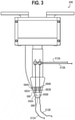
- FIG. 2A shows a cutout view of an embodiment of the starting device 468, also not according to the invention.
- the yarn 412 may extend through the outlet 488, which may be located in the dispensing area 456 of the feeder.
- the pressurized gas may be provided to the outlet 488 through the tube 490.
- the pressurized gas may quickly flow out of the bottom of the outlet 488, thereby directing the yarn towards out of the outlet 488 and towards a needle bed for engagement with a needle.
- Other embodiments are also contemplated (for example, in some embodiments, the yarn 412 does not share an outlet chamber with the tube 490 of pressurized gas).
- a feeder 508 has more than one dispensing area 556, where each dispensing area 556 is associated with a different yarn 512.
- a first dispensing area 556A for a first yarn 512A and a second dispensing area 556B for a second yarn 512B are included.
- more than two dispending areas for more than two respective yarns may be included.
- the feeder 508 includes a first cutting device 582A and a second cutting device 582B, where the first cutting device 582A and the second cutting device 582B are configured to cut the first yarn 512A and the second yarn 512B, respectively.
- a first gripping device 584A may be configured to grip the first yarn 512A
- a second gripping device 584B may be configured to grip the second yarn 512B.
- the first cutting device 582A and the second cutting device 582B may be individually and selectively actuatable, and similarly the first gripping device 584A and the second gripping device 584B may be individually and selectively actuatable.
- the first gripping device 584A may actuate when the first cutting device 582A actuates and the second gripping device 584B may actuate when the second cutting device 582B actuates.
- the feeder 508 also includes at least one starting device 586 configured to engage a cut end of at least one of the first yarn 512A and the second yarn 512B with the needle bed.
- the starting device 586 includes an outlet 588 for dispensing a pressurized gas to guide the cut end of the at least one of the yarns 512A, 512B to a needle of the needle bed during a starting procedure. While one outlet 588 may be sufficient to perform a starting procedure for both the first yarn 512A and the second yarn 512B, the feeder 508 may alternatively include an individual outlet associated with each of the yarns.
- the feeder 508 provides the ability to switch from knitting with the first yarn 512A to knitting with the second yarn 512B without manual intervention. This switch may occur before, after, or during the knitting of a course. Thus, it may provide the capability of switching between knitting with the first yarn 512A and the second yarn 512B on adjacent or spaced apart courses of a knitting component and/or within a single course of the knitting component. Further, a knitting machine with a feeder 508 capable of switching yarn types may be advantageous where more yarn types than feeders are desired.
- the feeder 508 is not limited to two yarns, and may include three or more yarns, where the feeder 508 has the devices and features described above with respect to each of (or at last a portion of) the three or more yarns. It is further contemplated that more than one dispensing area may dispense their respective yarns to a needle bed simultaneously, which may be advantageous where knitting with more than one yarn is desirable.
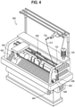
- the gripping device 684 of FIG. 4 described above when the gripping device 684 of FIG. 4 described above is activated, it may be desirable to provide the yarn 612 with a particular tension such that the yarn 612 does not develop slack that interferes with one of the needle beds 602, 604 and/or the knitting process. It also may be desirable to ensure that an appropriate tension is applied to the yarn 612 when, and if, the yarn 612 is re-engaged with at least one of the needle beds 602, 604 (as described above). Thus, it may be advantageous to include a tension system 694 for the knitting machine 600 depicted in FIG. 4 .
- the tension system 694 may include a tension controller 696 coupled to a frame of the knitting machine 600, as shown.
- the tension controller 696 may dispense the yarn 612 at a height suitable for a path of extension of the yarn 612 from the tension controller 696 to the feeder 608, for example.
- the yarn 612 may extend from the tension controller 696 to the feeder 608 in a path that is substantially parallel to the intersection of the needle beds 602, 604, but this is not required in all embodiments.
- the tension controller 696 may be any suitable mechanically controlled or digitally-controlled tension controller capable of managing and controlling the tension within the yarn 612.
- the tension controller 696 may have two driven rolls driven by a motor 698 in some embodiments.
- a spring-driven spool or bobbin 700 may manage slack upstream of the tension controller 696.
- the tension controller 696 may be capable of adjusting tension upon receipt of digital instructions such that the tension controller 696 is controllable via a digital electronic control system, which may be manually operated by a user and/or programmable.
- the tension controller 696 may be the last point of contact between the knitting machine 600 and the yarn 612 prior to the yarn 612 being received by the feeder 608.
- the tension controller 696 may therefore achieve precise control of the tension in the yarn 612 since no friction on the yarn 612 will occur between the tension controller 696 and the feeder 608. All upstream friction (e.g., friction due to guide devices 702 located upstream of the tension controller 696) may be absorbed by the tension controller 696 prior to reaching the feeder 608, and thus having respectively little or substantially no impact on the tension of the yarn 612 upon receipt by the feeder 608.
- a pulley 813 may be secured to a feeder arm 854 of a feeder 808, not according to the invention.
- the pulley 813 may include a yarn-receiving surface 815 configured to guide the yarn 812 as it extends to the dispensing area 856 of the feeder 808.
- the pulley 813 may have a relatively reduced effect on the tension of the yarn 812 at the dispensing area 856 due to relatively reduced friction with respect to other structures (e.g., an eyelet).
- tension controller may be included (like eyelets), and the friction associated with such devices may be ignored if determined tobe insubstantial, or may be dealt with by the tension controller at a location upstream of the feeder 808. It is further contemplated that at least one tension controller may be coupled to the feeder itself.
Landscapes
- Engineering & Computer Science (AREA)
- Textile Engineering (AREA)
- Knitting Machines (AREA)
Claims (12)
- Zuführeinrichtung (108, 508) für eine Strickmaschine (100), wobei die Zuführeinrichtung (108, 508) Folgendes umfasst:einen Halter, der für die Befestigung der Zuführeinrichtung (108, 508) an einer Strickmaschine (100) ausgebildet ist, so dass die Zuführeinrichtung (108, 508) bezogen auf eine Schiene (106) der Strickmaschine (100) entlang einer Achse beweglich ist,einen Zuführarm, der sich ausgehend von dem Halter (114) erstreckt, wobei der Zuführarm einen ersten Ausgabebereich (556A) und einen zweiten Ausgabebereich (556B) aufweist, die so ausgebildet sind, dass sie einem Nadelbett (102) der Strickmaschine ein erstes bzw. ein zweites Garn (512A, 512B) zuführen,eine erste und eine zweite Schneidvorrichtung (582A, 582B), die an den Zuführarm gekoppelt und so ausgebildet sind, dass sie das erste bzw. das zweite Garn schneiden, so dass diese vom Nadelbett (102) der Strickmaschine (100) gelöst werden,dadurch gekennzeichnet, dass der Zuführarm eine Anfangsvorrichtung (586) aufweist, die wenigstens einen Auslass (588) aufweist, der sich an einem Ende des Zuführarms befindet, wobei der Auslass (588) so ausgebildet ist, dass er ein Druckgas ausgibt, so dass wahlweise ein geschnittenes Ende des ersten Garns (512A) bzw. des zweiten Garns (512B) während eines Anfangsvorgangs zu einer Nadel des Nadelbetts (102) geführt wird,wobei der Auslass (588) zwischen dem ersten Ausgabebereich (556A) und dem zweiten Ausgabebereich (556B) gelegen ist, wobei der erste Ausgabebereich (556A) unterhalb der ersten Schneidvorrichtung (582A) gelegen ist und der zweite Ausgabebereich (556B) unterhalb der zweiten Schneidvorrichtung (582B) gelegen ist.
- Zuführeinrichtung (108, 508) nach Anspruch 1, wobei die erste Schneidvorrichtung (582A) eine Schneidkante zum Schneiden des ersten Garns (512A) aufweist, so dass ein oberer Abschnitt des ersten Garns (512A) von dem Nadelbett (102) der Strickmaschine (100) gelöst wird, wobei die zweite Schneidvorrichtung (582B) eine zweite Schneidkante zum Schneiden eines zweiten Garns (512B) aufweist, so dass ein oberer Abschnitt eines zweiten Garns (512B) von dem Nadelbett (102) der Strickmaschine (100) gelöst wird.
- Zuführeinrichtung (108, 508) nach Anspruch 2, ferner mit einer an den Zuführarm gekoppelten ersten Greifvorrichtung (584A) zum Greifen eines geschnittenen Endes des ersten Garns (512A), wenn das erste Garn (512A) von der ersten Schneidvorrichtung (582A) geschnitten wird, wobei die Zuführeinrichtung (108, 408) auch eine zweite Greifvorrichtung (584B) angrenzend an die zweite Schneidvorrichtung (582B) umfasst, zum Angreifen an dem zweiten Garn (512B), wenn das zweite Garn (512B) geschnitten wird, insbesondere
wobei die erste Greifvorrichtung (584A) so ausgebildet ist, dass sie von dem ersten Garn (512A) gelöst wird, wenn das erste Garn (512A) von dem ersten Ausgabebereich (556A) des Zuführarms zum Nadelbett (102) ausgegeben wird. - Zuführeinrichtung (108, 508) nach Anspruch 2, wobei die Anfangsvorrichtung (586) eine Strömung des Druckgases bewirkt.
- Zuführeinrichtung (108, 508) nach Anspruch 1, wobei der Zuführarm der Zuführeinrichtung (108, 508) einen einzelnen Auslass (588) aufweist, der zum Zuführen des ersten Garns (512A) und des zweiten Garns (512B) zum Nadelbett (102) der Strickmaschine (100) ausgebildet ist,wobei der Auslass (588) zum Ausgeben des Druckgases ausgebildet ist, so dass das geschnittene Ende des ersten Garns (512A) und des zweiten Garns (512B) während des Anfangsvorgangs zur Nadel des Nadelbetts (102) geführt wird,wobei die erste Schneidvorrichtung (582A) so ausgebildet ist, dass sie das erste Garn (512A) schneidet, ohne das zweite Garn (512B) zu schneiden, und wobei die zweite Schneidvorrichtung (582B) so ausgebildet ist, dass sie das zweite Garn (512B) schneidet, ohne das erste Garn (512A) zu schneiden.
- Zuführeinrichtung (108, 508) nach Anspruch 1, ferner mit einer an den Zuführarm gekoppelten ersten Greifvorrichtung (584A) zum Greifen des geschnittenen Endes des ersten Garns (512A), wenn das erste Garn (512A) von der ersten Schneidvorrichtung (582A) geschnitten wird, wobei die Zuführeinrichtung (108, 508) auch eine an den Zuführarm gekoppelte zweite Greifvorrichtung (584B) umfasst, zum Greifen des geschnittenen Endes des zweiten Garns (512B), wenn das zweite Garn (512B) von der zweiten Schneidvorrichtung (582B) geschnitten wird.
- Zuführeinrichtung (108, 508) nach Anspruch 6, wobei die erste Greifvorrichtung (584A) so ausgebildet ist, dass sie von dem ersten Garn (512A) gelöst wird, wenn das erste Garn (512A) an einem ersten Ausgabebereich (556A) des Zuführarms zum Nadelbett (102) ausgegeben wird.
- Zuführeinrichtung (108, 508) nach Anspruch 5, wobei die Anfangsvorrichtung (586) eine Strömung des Druckgases bewirkt.
- Zuführeinrichtung (108, 508) nach Anspruch 5, wobei die erste Schneidvorrichtung (582A) durch die Bewegung des an den Halter gekoppelten Zuführarms betätigt wird.
- Verfahren, wobei das Verfahren Folgendes umfasst:Stricken mit einem ersten Garn (512A) mittels einer Zuführeinrichtung (108, 508), derart, dass sich das erste Garn (512A) durch einen ersten Ausgabebereich (556A) an einem Ende eines Zuführarms der Zuführeinrichtung (108, 508) bewegt,Schneiden des ersten Garns (512A) mittels einer ersten Schneidvorrichtung (582A), wobei die erste Schneidvorrichtung (582A) an den Zuführarm der Zuführeinrichtung (108, 508) gekoppelt ist,Greifen des ersten Garns (512A) mittels einer ersten Greifvorrichtung (584A), wobei die erste Greifvorrichtung (584A) an den Zuführarm der Zuführeinrichtung (108, 508) gekoppelt ist, undIn-Eingriff-Bringen eines zweiten Garns (512B) mit einem Nadelbett (102) unter Verwendung einer Anfangsvorrichtung (586), die wenigstens einen Auslass (588) aufweist, vor dem Stricken mit dem zweiten Garn (512B),Stricken mit dem zweiten Garn (512B) mittels der Zuführeinrichtung, derart, dass sich das zweite Garn (512B) durch einen zweiten Ausgabebereich (556B) am Ende des Zuführarms der Zuführeinrichtung (108, 508) bewegt,wobei der Zuführarm der Zuführeinrichtung (108, 508) den Auslass (588) aufweist, der sich an einem Ende des Zuführarms der Zuführeinrichtung (108, 508) befindet, wobei der Auslass (588) so ausgebildet ist, dass er ein Druckgas ausgibt, so dass wahlweise ein geschnittenes Ende des ersten Garns (512A) bzw. eines zweiten Garns (512B) zu einer Nadel eines Nadelbetts (102) einer Strickmaschine (100) geführt wird, undwobei der Auslass (588) zwischen dem ersten Ausgabebereich (556A) und dem zweiten Ausgabebereich (556B) gelegen ist, wobei der erste Ausgabebereich (556A) das erste Garn (512A) während des Strickens des ersten Garns (512A) ausgibt und der zweite Ausgabebereich (556B) das zweite Garn (512B) während des Strickens des zweiten Garns (512B) ausgibt.
- Verfahren nach Anspruch 10, das ferner Folgendes umfasst:Schneiden des zweiten Garns (512B) mittels einer zweiten Schneidvorrichtung (582B), die an den Zuführarm der Zuführeinrichtung (108, 508) gekoppelt ist,Greifen des zweiten Garns (512B) mittels einer zweiten Greifvorrichtung (584B), die an den Zuführarm der Zuführeinrichtung (108, 508) gekoppelt ist, underneutes Stricken mit dem ersten Garn (512A) mittels der Zuführeinrichtung (108, 508).
- Verfahren nach Anspruch 10,
wobei bei dem In-Eingriff-Bringen des zweiten Garns (512B) mit dem Nadelbett (102) das Druckgas abgegeben wird, so dass das zweite Garn (512B) zum Nadelbett (102) geführt wird.
Applications Claiming Priority (3)
| Application Number | Priority Date | Filing Date | Title |
|---|---|---|---|
| US201762479718P | 2017-03-31 | 2017-03-31 | |
| EP18718657.2A EP3601648B1 (de) | 2017-03-31 | 2018-03-30 | Fadenführer mit einer schneidvorrichtung |
| PCT/US2018/025361 WO2018183818A1 (en) | 2017-03-31 | 2018-03-30 | Knitting feeder with a cutting device |
Related Parent Applications (1)
| Application Number | Title | Priority Date | Filing Date |
|---|---|---|---|
| EP18718657.2A Division EP3601648B1 (de) | 2017-03-31 | 2018-03-30 | Fadenführer mit einer schneidvorrichtung |
Publications (2)
| Publication Number | Publication Date |
|---|---|
| EP3786327A1 EP3786327A1 (de) | 2021-03-03 |
| EP3786327B1 true EP3786327B1 (de) | 2022-02-23 |
Family
ID=62017611
Family Applications (3)
| Application Number | Title | Priority Date | Filing Date |
|---|---|---|---|
| EP20188250.3A Active EP3786327B1 (de) | 2017-03-31 | 2018-03-30 | Fadenführer mit einer schneidvorrichtung |
| EP18718657.2A Active EP3601648B1 (de) | 2017-03-31 | 2018-03-30 | Fadenführer mit einer schneidvorrichtung |
| EP18719000.4A Withdrawn EP3601649A1 (de) | 2017-03-31 | 2018-03-30 | Kolbensysteme und multifunktionszuführvorrichtungen für eine strickmaschine |
Family Applications After (2)
| Application Number | Title | Priority Date | Filing Date |
|---|---|---|---|
| EP18718657.2A Active EP3601648B1 (de) | 2017-03-31 | 2018-03-30 | Fadenführer mit einer schneidvorrichtung |
| EP18719000.4A Withdrawn EP3601649A1 (de) | 2017-03-31 | 2018-03-30 | Kolbensysteme und multifunktionszuführvorrichtungen für eine strickmaschine |
Country Status (5)
| Country | Link |
|---|---|
| US (2) | US20180282916A1 (de) |
| EP (3) | EP3786327B1 (de) |
| CN (2) | CN110691869A (de) |
| TW (2) | TWM572902U (de) |
| WO (2) | WO2018183818A1 (de) |
Families Citing this family (6)
| Publication number | Priority date | Publication date | Assignee | Title |
|---|---|---|---|---|
| WO2020123448A1 (en) * | 2018-12-10 | 2020-06-18 | Nike Innovate C.V. | Knitted component with vertical inlay, a method of making same and a knitting machine suitable therefore |
| US11421354B2 (en) * | 2019-02-27 | 2022-08-23 | Pai Lung Machinery Mill Co., Ltd. | Flat knitting machine yarn feeder with variable yarn feeding positions |
| IT201900007821A1 (it) * | 2019-06-03 | 2020-12-03 | Lonati Spa | Struttura di tomaia e procedimento per la produzione di una struttura di tomaia. |
| JP7438007B2 (ja) | 2020-04-23 | 2024-02-26 | 株式会社島精機製作所 | 横編機用の糸状体の挿入装置 |
| JP7460477B2 (ja) | 2020-08-05 | 2024-04-02 | 株式会社島精機製作所 | 糸管理システム |
| JP2025537029A (ja) * | 2023-06-06 | 2025-11-12 | シンセテック (フーチエン) テクノロジー カンパニー リミテッド | 可動糸ノズルを有する糸ガイド台、紋様組織、織物、フライニット織物及びその編成プロセス |
Family Cites Families (27)
| Publication number | Priority date | Publication date | Assignee | Title |
|---|---|---|---|---|
| US2357708A (en) * | 1941-05-21 | 1944-09-05 | Toone Nottingham Ltd B | Knitting machine |
| US2384214A (en) * | 1942-08-25 | 1945-09-04 | Toone Nottingham Ltd B | Knitting machine |
| GB761975A (en) * | 1953-02-26 | 1956-11-21 | Toone Nottingham Ltd B | Improvements in or relating to knitting machines |
| US2838923A (en) * | 1955-02-07 | 1958-06-17 | Frederic H Lassiter | Yarn tension controlled yarn feeding apparatus |
| US2934922A (en) * | 1957-04-26 | 1960-05-03 | Textile Machine Works | Yarn clamping and severing means for knitting machines |
| US3252307A (en) * | 1963-02-15 | 1966-05-24 | Textile Machine Works | Yarn severing means for knitting machines |
| GB1269109A (en) * | 1969-11-29 | 1972-04-06 | Wildt Mellor Bromley Ltd | Improved electro-magnetic means for selective control of yarn feed changes in flat knitting machines |
| JPS49111B1 (de) * | 1970-12-15 | 1974-01-05 | ||
| US3890809A (en) * | 1973-02-20 | 1975-06-24 | Riccardo Tenconi | Circular knitting machine with pneumatic thread feeding devices |
| GB1586864A (en) * | 1976-09-18 | 1981-03-25 | Wildt Mellor Bromley Ltd | Yarn feed and yarn change mechanism for a knitting machine |
| JPS5685449A (en) * | 1979-12-10 | 1981-07-11 | Shima Idea Center | Yarn guide lever moving control apparatus in traverse knitting machine |
| DD227465A1 (de) * | 1984-10-15 | 1985-09-18 | Textima Veb K | Fadenfuehrersteuervorrichtung fuer strickmaschinen |
| DE3606821A1 (de) | 1985-08-19 | 1987-02-26 | Stoll & Co H | Einrichtung zur einstellung des verstellweges der fadenfuehrer einer flachstrickmaschine |
| DE3716931C1 (de) * | 1986-07-01 | 1988-01-28 | Stoll & Co H | Fadenfuehrerschlitten |
| DE3715297A1 (de) * | 1987-05-08 | 1988-11-24 | Stoll & Co H | Verfahren und einrichtung zum behandeln der strickgarne laengs des gestrickrandes |
| IT214303Z2 (it) * | 1988-03-01 | 1990-05-03 | Emm Srl | Dispositivo perfezionato per il supporto del guidafilo di una macchina automatica rettilinea per maglieria |
| US5623840A (en) * | 1992-07-08 | 1997-04-29 | Tecnit-Technische Textilien Und Systeme Gmbh | Process for production of weave-knit material |
| IT1289292B1 (it) * | 1996-05-31 | 1998-10-02 | A R M I S R L | Perfezionamenti ad un metodo e ad una apparecchiatura per l'imbrigliamento in corso di tessitura di porzioni terminali di filo |
| JPH11335970A (ja) | 1998-05-22 | 1999-12-07 | Kanebo Ltd | 抗菌性ポリエステル繊維布帛およびその製造方法 |
| JP4015973B2 (ja) * | 2003-07-30 | 2007-11-28 | 株式会社島精機製作所 | 編糸保持切断方法および装置 |
| JP4015980B2 (ja) * | 2003-09-19 | 2007-11-28 | 株式会社島精機製作所 | 横編機の端糸処理装置および方法 |
| EP1788131B1 (de) * | 2005-11-16 | 2016-05-04 | H. Stoll AG & Co. KG | Flachstrickmaschine mit einer Vorrichtung zur Mitnahme von Funktionselementen |
| EP1788132B1 (de) * | 2005-11-17 | 2011-08-17 | H. Stoll GmbH & Co. KG | Flachstrickmaschine mit einem Fadenführer |
| US9060570B2 (en) | 2011-03-15 | 2015-06-23 | Nike, Inc. | Method of manufacturing a knitted component |
| FR3008432A1 (fr) * | 2013-07-10 | 2015-01-16 | Steiger Participations Sa | Dispositif de pincement et de coupe pour une machine a tricoter rectiligne |
| EP2843095A1 (de) * | 2013-08-29 | 2015-03-04 | H. Stoll GmbH & Co. KG | Flachstrickmaschine mit quer zum Nadelbett bewegbarem Fadenführer |
| CN203938841U (zh) * | 2014-05-14 | 2014-11-12 | 湖州石淙印染有限公司 | 一种横机用的导纱装置 |
-
2018
- 2018-03-30 EP EP20188250.3A patent/EP3786327B1/de active Active
- 2018-03-30 CN CN201880036250.7A patent/CN110691869A/zh active Pending
- 2018-03-30 WO PCT/US2018/025361 patent/WO2018183818A1/en not_active Ceased
- 2018-03-30 EP EP18718657.2A patent/EP3601648B1/de active Active
- 2018-03-30 WO PCT/US2018/025355 patent/WO2018183813A1/en not_active Ceased
- 2018-03-30 CN CN201880023251.8A patent/CN110475922B/zh active Active
- 2018-03-30 EP EP18719000.4A patent/EP3601649A1/de not_active Withdrawn
- 2018-03-30 US US15/941,032 patent/US20180282916A1/en not_active Abandoned
- 2018-03-30 US US15/941,037 patent/US11408105B2/en active Active
- 2018-03-31 TW TW107204277U patent/TWM572902U/zh unknown
- 2018-03-31 TW TW107204241U patent/TWM572378U/zh unknown
Also Published As
| Publication number | Publication date |
|---|---|
| CN110691869A (zh) | 2020-01-14 |
| US11408105B2 (en) | 2022-08-09 |
| EP3601648B1 (de) | 2020-07-29 |
| EP3786327A1 (de) | 2021-03-03 |
| CN110475922A (zh) | 2019-11-19 |
| US20180282914A1 (en) | 2018-10-04 |
| WO2018183818A1 (en) | 2018-10-04 |
| WO2018183813A1 (en) | 2018-10-04 |
| US20180282916A1 (en) | 2018-10-04 |
| EP3601648A1 (de) | 2020-02-05 |
| EP3601649A1 (de) | 2020-02-05 |
| TWM572378U (zh) | 2019-01-01 |
| CN110475922B (zh) | 2022-01-04 |
| TWM572902U (zh) | 2019-01-11 |
Similar Documents
| Publication | Publication Date | Title |
|---|---|---|
| EP3601648B1 (de) | Fadenführer mit einer schneidvorrichtung | |
| EP2937452B1 (de) | Verfahren zur herstellung von strickware, maschenware und nahtloses textil mit variabler kompression | |
| EP3315642B1 (de) | Plattier-strickverfahren und flachstrickmaschine für das verfahren | |
| CN111350014A (zh) | 一种汗布贴合割绒布的针织圆纬机用针织工艺 | |
| EP1842948A4 (de) | Verfahren zur herstellung einer doppelschlauchware auf der flachstrickmaschine | |
| US20230002941A1 (en) | Knitting Machine with Extreme Racking and Related Knitted Component | |
| US11286594B2 (en) | Knitting machine with electronic auxiliary component | |
| HK40017251A (en) | Knitting feeder with a cutting device | |
| HK40017251B (en) | Knitting feeder with a cutting device | |
| KR101155205B1 (ko) | 색상 무늬 메쉬를 형성하는 직물 편직기 | |
| JP2010133060A (ja) | ダブル編用丸編機 | |
| US10612169B2 (en) | Knitting mechanism for circular knitting machine and the circular knitting machine | |
| US3606771A (en) | Yarn feeder control mechanism for circular knitting machines | |
| CN104342837B (zh) | 用于在横机上制造针织物的方法 | |
| US302928A (en) | Looping attachment foe knitting machines | |
| ITMI970703A1 (it) | Complesso di camme di comando delle platine di abbattitura per macchine circolari per maglieria o calzetteria per la produzione di |
Legal Events
| Date | Code | Title | Description |
|---|---|---|---|
| PUAI | Public reference made under article 153(3) epc to a published international application that has entered the european phase |
Free format text: ORIGINAL CODE: 0009012 |
|
| STAA | Information on the status of an ep patent application or granted ep patent |
Free format text: STATUS: REQUEST FOR EXAMINATION WAS MADE |
|
| 17P | Request for examination filed |
Effective date: 20200728 |
|
| AC | Divisional application: reference to earlier application |
Ref document number: 3601648 Country of ref document: EP Kind code of ref document: P |
|
| AK | Designated contracting states |
Kind code of ref document: A1 Designated state(s): AL AT BE BG CH CY CZ DE DK EE ES FI FR GB GR HR HU IE IS IT LI LT LU LV MC MK MT NL NO PL PT RO RS SE SI SK SM TR |
|
| GRAP | Despatch of communication of intention to grant a patent |
Free format text: ORIGINAL CODE: EPIDOSNIGR1 |
|
| STAA | Information on the status of an ep patent application or granted ep patent |
Free format text: STATUS: GRANT OF PATENT IS INTENDED |
|
| INTG | Intention to grant announced |
Effective date: 20210915 |
|
| GRAS | Grant fee paid |
Free format text: ORIGINAL CODE: EPIDOSNIGR3 |
|
| GRAA | (expected) grant |
Free format text: ORIGINAL CODE: 0009210 |
|
| STAA | Information on the status of an ep patent application or granted ep patent |
Free format text: STATUS: THE PATENT HAS BEEN GRANTED |
|
| AC | Divisional application: reference to earlier application |
Ref document number: 3601648 Country of ref document: EP Kind code of ref document: P |
|
| AK | Designated contracting states |
Kind code of ref document: B1 Designated state(s): AL AT BE BG CH CY CZ DE DK EE ES FI FR GB GR HR HU IE IS IT LI LT LU LV MC MK MT NL NO PL PT RO RS SE SI SK SM TR |
|
| REG | Reference to a national code |
Ref country code: GB Ref legal event code: FG4D |
|
| REG | Reference to a national code |
Ref country code: CH Ref legal event code: EP |
|
| REG | Reference to a national code |
Ref country code: AT Ref legal event code: REF Ref document number: 1470548 Country of ref document: AT Kind code of ref document: T Effective date: 20220315 |
|
| REG | Reference to a national code |
Ref country code: IE Ref legal event code: FG4D |
|
| REG | Reference to a national code |
Ref country code: DE Ref legal event code: R096 Ref document number: 602018031442 Country of ref document: DE |
|
| REG | Reference to a national code |
Ref country code: LT Ref legal event code: MG9D |
|
| REG | Reference to a national code |
Ref country code: NL Ref legal event code: MP Effective date: 20220223 |
|
| REG | Reference to a national code |
Ref country code: AT Ref legal event code: MK05 Ref document number: 1470548 Country of ref document: AT Kind code of ref document: T Effective date: 20220223 |
|
| PG25 | Lapsed in a contracting state [announced via postgrant information from national office to epo] |
Ref country code: SE Free format text: LAPSE BECAUSE OF FAILURE TO SUBMIT A TRANSLATION OF THE DESCRIPTION OR TO PAY THE FEE WITHIN THE PRESCRIBED TIME-LIMIT Effective date: 20220223 Ref country code: RS Free format text: LAPSE BECAUSE OF FAILURE TO SUBMIT A TRANSLATION OF THE DESCRIPTION OR TO PAY THE FEE WITHIN THE PRESCRIBED TIME-LIMIT Effective date: 20220223 Ref country code: PT Free format text: LAPSE BECAUSE OF FAILURE TO SUBMIT A TRANSLATION OF THE DESCRIPTION OR TO PAY THE FEE WITHIN THE PRESCRIBED TIME-LIMIT Effective date: 20220623 Ref country code: NO Free format text: LAPSE BECAUSE OF FAILURE TO SUBMIT A TRANSLATION OF THE DESCRIPTION OR TO PAY THE FEE WITHIN THE PRESCRIBED TIME-LIMIT Effective date: 20220523 Ref country code: NL Free format text: LAPSE BECAUSE OF FAILURE TO SUBMIT A TRANSLATION OF THE DESCRIPTION OR TO PAY THE FEE WITHIN THE PRESCRIBED TIME-LIMIT Effective date: 20220223 Ref country code: LT Free format text: LAPSE BECAUSE OF FAILURE TO SUBMIT A TRANSLATION OF THE DESCRIPTION OR TO PAY THE FEE WITHIN THE PRESCRIBED TIME-LIMIT Effective date: 20220223 Ref country code: HR Free format text: LAPSE BECAUSE OF FAILURE TO SUBMIT A TRANSLATION OF THE DESCRIPTION OR TO PAY THE FEE WITHIN THE PRESCRIBED TIME-LIMIT Effective date: 20220223 Ref country code: ES Free format text: LAPSE BECAUSE OF FAILURE TO SUBMIT A TRANSLATION OF THE DESCRIPTION OR TO PAY THE FEE WITHIN THE PRESCRIBED TIME-LIMIT Effective date: 20220223 Ref country code: BG Free format text: LAPSE BECAUSE OF FAILURE TO SUBMIT A TRANSLATION OF THE DESCRIPTION OR TO PAY THE FEE WITHIN THE PRESCRIBED TIME-LIMIT Effective date: 20220523 |
|
| PG25 | Lapsed in a contracting state [announced via postgrant information from national office to epo] |
Ref country code: PL Free format text: LAPSE BECAUSE OF FAILURE TO SUBMIT A TRANSLATION OF THE DESCRIPTION OR TO PAY THE FEE WITHIN THE PRESCRIBED TIME-LIMIT Effective date: 20220223 Ref country code: LV Free format text: LAPSE BECAUSE OF FAILURE TO SUBMIT A TRANSLATION OF THE DESCRIPTION OR TO PAY THE FEE WITHIN THE PRESCRIBED TIME-LIMIT Effective date: 20220223 Ref country code: GR Free format text: LAPSE BECAUSE OF FAILURE TO SUBMIT A TRANSLATION OF THE DESCRIPTION OR TO PAY THE FEE WITHIN THE PRESCRIBED TIME-LIMIT Effective date: 20220524 Ref country code: FI Free format text: LAPSE BECAUSE OF FAILURE TO SUBMIT A TRANSLATION OF THE DESCRIPTION OR TO PAY THE FEE WITHIN THE PRESCRIBED TIME-LIMIT Effective date: 20220223 Ref country code: AT Free format text: LAPSE BECAUSE OF FAILURE TO SUBMIT A TRANSLATION OF THE DESCRIPTION OR TO PAY THE FEE WITHIN THE PRESCRIBED TIME-LIMIT Effective date: 20220223 |
|
| PG25 | Lapsed in a contracting state [announced via postgrant information from national office to epo] |
Ref country code: IS Free format text: LAPSE BECAUSE OF FAILURE TO SUBMIT A TRANSLATION OF THE DESCRIPTION OR TO PAY THE FEE WITHIN THE PRESCRIBED TIME-LIMIT Effective date: 20220623 |
|
| PG25 | Lapsed in a contracting state [announced via postgrant information from national office to epo] |
Ref country code: SM Free format text: LAPSE BECAUSE OF FAILURE TO SUBMIT A TRANSLATION OF THE DESCRIPTION OR TO PAY THE FEE WITHIN THE PRESCRIBED TIME-LIMIT Effective date: 20220223 Ref country code: SK Free format text: LAPSE BECAUSE OF FAILURE TO SUBMIT A TRANSLATION OF THE DESCRIPTION OR TO PAY THE FEE WITHIN THE PRESCRIBED TIME-LIMIT Effective date: 20220223 Ref country code: RO Free format text: LAPSE BECAUSE OF FAILURE TO SUBMIT A TRANSLATION OF THE DESCRIPTION OR TO PAY THE FEE WITHIN THE PRESCRIBED TIME-LIMIT Effective date: 20220223 Ref country code: EE Free format text: LAPSE BECAUSE OF FAILURE TO SUBMIT A TRANSLATION OF THE DESCRIPTION OR TO PAY THE FEE WITHIN THE PRESCRIBED TIME-LIMIT Effective date: 20220223 Ref country code: DK Free format text: LAPSE BECAUSE OF FAILURE TO SUBMIT A TRANSLATION OF THE DESCRIPTION OR TO PAY THE FEE WITHIN THE PRESCRIBED TIME-LIMIT Effective date: 20220223 Ref country code: CZ Free format text: LAPSE BECAUSE OF FAILURE TO SUBMIT A TRANSLATION OF THE DESCRIPTION OR TO PAY THE FEE WITHIN THE PRESCRIBED TIME-LIMIT Effective date: 20220223 |
|
| REG | Reference to a national code |
Ref country code: CH Ref legal event code: PL |
|
| REG | Reference to a national code |
Ref country code: DE Ref legal event code: R097 Ref document number: 602018031442 Country of ref document: DE |
|
| PG25 | Lapsed in a contracting state [announced via postgrant information from national office to epo] |
Ref country code: MC Free format text: LAPSE BECAUSE OF FAILURE TO SUBMIT A TRANSLATION OF THE DESCRIPTION OR TO PAY THE FEE WITHIN THE PRESCRIBED TIME-LIMIT Effective date: 20220223 Ref country code: AL Free format text: LAPSE BECAUSE OF FAILURE TO SUBMIT A TRANSLATION OF THE DESCRIPTION OR TO PAY THE FEE WITHIN THE PRESCRIBED TIME-LIMIT Effective date: 20220223 |
|
| REG | Reference to a national code |
Ref country code: BE Ref legal event code: MM Effective date: 20220331 |
|
| PLBE | No opposition filed within time limit |
Free format text: ORIGINAL CODE: 0009261 |
|
| STAA | Information on the status of an ep patent application or granted ep patent |
Free format text: STATUS: NO OPPOSITION FILED WITHIN TIME LIMIT |
|
| PG25 | Lapsed in a contracting state [announced via postgrant information from national office to epo] |
Ref country code: LU Free format text: LAPSE BECAUSE OF NON-PAYMENT OF DUE FEES Effective date: 20220330 Ref country code: LI Free format text: LAPSE BECAUSE OF NON-PAYMENT OF DUE FEES Effective date: 20220331 Ref country code: IE Free format text: LAPSE BECAUSE OF NON-PAYMENT OF DUE FEES Effective date: 20220330 Ref country code: CH Free format text: LAPSE BECAUSE OF NON-PAYMENT OF DUE FEES Effective date: 20220331 |
|
| 26N | No opposition filed |
Effective date: 20221124 |
|
| PG25 | Lapsed in a contracting state [announced via postgrant information from national office to epo] |
Ref country code: SI Free format text: LAPSE BECAUSE OF FAILURE TO SUBMIT A TRANSLATION OF THE DESCRIPTION OR TO PAY THE FEE WITHIN THE PRESCRIBED TIME-LIMIT Effective date: 20220223 Ref country code: BE Free format text: LAPSE BECAUSE OF NON-PAYMENT OF DUE FEES Effective date: 20220331 |
|
| P01 | Opt-out of the competence of the unified patent court (upc) registered |
Effective date: 20230515 |
|
| PG25 | Lapsed in a contracting state [announced via postgrant information from national office to epo] |
Ref country code: IT Free format text: LAPSE BECAUSE OF FAILURE TO SUBMIT A TRANSLATION OF THE DESCRIPTION OR TO PAY THE FEE WITHIN THE PRESCRIBED TIME-LIMIT Effective date: 20220223 |
|
| PG25 | Lapsed in a contracting state [announced via postgrant information from national office to epo] |
Ref country code: MK Free format text: LAPSE BECAUSE OF FAILURE TO SUBMIT A TRANSLATION OF THE DESCRIPTION OR TO PAY THE FEE WITHIN THE PRESCRIBED TIME-LIMIT Effective date: 20220223 Ref country code: CY Free format text: LAPSE BECAUSE OF FAILURE TO SUBMIT A TRANSLATION OF THE DESCRIPTION OR TO PAY THE FEE WITHIN THE PRESCRIBED TIME-LIMIT Effective date: 20220223 |
|
| PG25 | Lapsed in a contracting state [announced via postgrant information from national office to epo] |
Ref country code: HU Free format text: LAPSE BECAUSE OF FAILURE TO SUBMIT A TRANSLATION OF THE DESCRIPTION OR TO PAY THE FEE WITHIN THE PRESCRIBED TIME-LIMIT; INVALID AB INITIO Effective date: 20180330 |
|
| PG25 | Lapsed in a contracting state [announced via postgrant information from national office to epo] |
Ref country code: TR Free format text: LAPSE BECAUSE OF FAILURE TO SUBMIT A TRANSLATION OF THE DESCRIPTION OR TO PAY THE FEE WITHIN THE PRESCRIBED TIME-LIMIT Effective date: 20220223 |
|
| PG25 | Lapsed in a contracting state [announced via postgrant information from national office to epo] |
Ref country code: MT Free format text: LAPSE BECAUSE OF FAILURE TO SUBMIT A TRANSLATION OF THE DESCRIPTION OR TO PAY THE FEE WITHIN THE PRESCRIBED TIME-LIMIT Effective date: 20220223 |
|
| REG | Reference to a national code |
Ref country code: DE Ref legal event code: R082 Ref document number: 602018031442 Country of ref document: DE Representative=s name: MUELLER-BORE & PARTNER PATENTANWAELTE PARTG MB, DE |
|
| PGFP | Annual fee paid to national office [announced via postgrant information from national office to epo] |
Ref country code: FR Payment date: 20251231 Year of fee payment: 9 |
|
| PGFP | Annual fee paid to national office [announced via postgrant information from national office to epo] |
Ref country code: GB Payment date: 20260106 Year of fee payment: 9 |
|
| PGFP | Annual fee paid to national office [announced via postgrant information from national office to epo] |
Ref country code: DE Payment date: 20260102 Year of fee payment: 9 |