EP3784974B2 - Plattenwärmetauscher, verfahrenstechnische anlage und verfahren - Google Patents
Plattenwärmetauscher, verfahrenstechnische anlage und verfahren Download PDFInfo
- Publication number
- EP3784974B2 EP3784974B2 EP19720366.4A EP19720366A EP3784974B2 EP 3784974 B2 EP3784974 B2 EP 3784974B2 EP 19720366 A EP19720366 A EP 19720366A EP 3784974 B2 EP3784974 B2 EP 3784974B2
- Authority
- EP
- European Patent Office
- Prior art keywords
- separating plate
- optical waveguide
- separating
- heat exchanger
- plate
- Prior art date
- Legal status (The legal status is an assumption and is not a legal conclusion. Google has not performed a legal analysis and makes no representation as to the accuracy of the status listed.)
- Active
Links
Images


Classifications
-
- F—MECHANICAL ENGINEERING; LIGHTING; HEATING; WEAPONS; BLASTING
- F28—HEAT EXCHANGE IN GENERAL
- F28D—HEAT-EXCHANGE APPARATUS, NOT PROVIDED FOR IN ANOTHER SUBCLASS, IN WHICH THE HEAT-EXCHANGE MEDIA DO NOT COME INTO DIRECT CONTACT
- F28D9/00—Heat-exchange apparatus having stationary plate-like or laminated conduit assemblies for both heat-exchange media, the media being in contact with different sides of a conduit wall
- F28D9/0062—Heat-exchange apparatus having stationary plate-like or laminated conduit assemblies for both heat-exchange media, the media being in contact with different sides of a conduit wall the conduits for one heat-exchange medium being formed by spaced plates with inserted elements
-
- F—MECHANICAL ENGINEERING; LIGHTING; HEATING; WEAPONS; BLASTING
- F28—HEAT EXCHANGE IN GENERAL
- F28F—DETAILS OF HEAT-EXCHANGE AND HEAT-TRANSFER APPARATUS, OF GENERAL APPLICATION
- F28F27/00—Control arrangements or safety devices specially adapted for heat-exchange or heat-transfer apparatus
-
- F—MECHANICAL ENGINEERING; LIGHTING; HEATING; WEAPONS; BLASTING
- F28—HEAT EXCHANGE IN GENERAL
- F28F—DETAILS OF HEAT-EXCHANGE AND HEAT-TRANSFER APPARATUS, OF GENERAL APPLICATION
- F28F3/00—Plate-like or laminated elements; Assemblies of plate-like or laminated elements
- F28F3/12—Elements constructed in the shape of a hollow panel, e.g. with channels
-
- G—PHYSICS
- G01—MEASURING; TESTING
- G01K—MEASURING TEMPERATURE; MEASURING QUANTITY OF HEAT; THERMALLY-SENSITIVE ELEMENTS NOT OTHERWISE PROVIDED FOR
- G01K1/00—Details of thermometers not specially adapted for particular types of thermometer
- G01K1/14—Supports; Fastening devices; Arrangements for mounting thermometers in particular locations
-
- F—MECHANICAL ENGINEERING; LIGHTING; HEATING; WEAPONS; BLASTING
- F28—HEAT EXCHANGE IN GENERAL
- F28F—DETAILS OF HEAT-EXCHANGE AND HEAT-TRANSFER APPARATUS, OF GENERAL APPLICATION
- F28F2200/00—Prediction; Simulation; Testing
-
- G—PHYSICS
- G01—MEASURING; TESTING
- G01K—MEASURING TEMPERATURE; MEASURING QUANTITY OF HEAT; THERMALLY-SENSITIVE ELEMENTS NOT OTHERWISE PROVIDED FOR
- G01K1/00—Details of thermometers not specially adapted for particular types of thermometer
- G01K1/14—Supports; Fastening devices; Arrangements for mounting thermometers in particular locations
- G01K1/143—Supports; Fastening devices; Arrangements for mounting thermometers in particular locations for measuring surface temperatures
-
- G—PHYSICS
- G01—MEASURING; TESTING
- G01K—MEASURING TEMPERATURE; MEASURING QUANTITY OF HEAT; THERMALLY-SENSITIVE ELEMENTS NOT OTHERWISE PROVIDED FOR
- G01K11/00—Measuring temperature based upon physical or chemical changes not covered by groups G01K3/00, G01K5/00, G01K7/00 or G01K9/00
- G01K11/32—Measuring temperature based upon physical or chemical changes not covered by groups G01K3/00, G01K5/00, G01K7/00 or G01K9/00 using changes in transmittance, scattering or luminescence in optical fibres
Definitions
- the invention relates to a plate heat exchanger for a process engineering plant, a process engineering plant with such a plate heat exchanger and a method for producing such a plate heat exchanger.
- So-called plate heat exchangers comprise a large number of fins or fins between which separating plates are arranged.
- the separating plates separate adjacent heat transfer passages from one another in such a way that a material transfer between the heat transfer passages is prevented, but heat transfer is enabled.
- Thermal stresses as a result of different thermal expansions from differential temperature differences can, however, lead to mechanical damage to the tightness between the heat transfer passages and even to the plate heat exchanger becoming leaky compared to its surroundings.
- a plate heat exchanger can, for example, be equipped with a temperature measurement on a surface of its outer skin.
- the temperatures on the outer skin only provide a local value, which can be used to draw conclusions about the temperature inside the plate heat exchanger under certain assumptions.
- these temperature measurements can be influenced by environmental influences due to the measurement on the outer skin.
- the WO 2014/056587 A1 describes a plate heat exchanger with an optical fiber for temperature measurement.
- the optical fiber is positioned in an open groove that is provided either in a fin or in a separating plate of the plate heat exchanger.
- an object of the present invention is to provide an improved heat exchanger.
- the optical fiber is arranged inside the separating plate, damage to the optical fiber can be prevented.
- high-resolution and precise temperature measurement is possible directly in the separating plate and therefore also inside the plate heat exchanger. Because the optical fiber is integrated into the separating plate, no additional or at least only a small amount of additional installation space is required to record the temperature distribution and/or expansion distribution. Because the separating plate is arranged inside the plate heat exchanger, the measured temperature is not influenced by environmental influences. Both expansion measurements and temperature measurements can be carried out using the optical fiber. The component's safety against failure or leaks inside or outside is increased.
- the fact that the fins and the separating plates are arranged "alternately" means that a separating plate is arranged between two fins and a fin is arranged between two separating plates.
- the number of fins and the number of separating plates is basically arbitrary.
- the fins and the separating plates are positioned in particular between two cover plates of the plate heat exchanger. Layers formed by the fins, so-called fin layers, form so-called passages, in particular heat transfer passages, which are separated from the environment by edge strips or sidebars.
- the optical fiber is preferably a fiber optic sensor cable.
- the optical fiber can thus be a sensor element of a measuring device of the plate heat exchanger.
- the plane spanned by the at least one separating plate preferably runs centrally through the at least one separating plate in such a way that it is preferably constructed mirror-symmetrically with respect to the plane.
- the at least one separating plate preferably has a rectangular geometry, wherein the separating plate can have a thickness of approximately 1 to 2 mm.
- the at least one separating plate is therefore not thicker or only slightly thicker than a separating plate without such an optical waveguide.
- the separating plates can be referred to as separating plates.
- the lamellae can be referred to as fins.
- Several separating plates can be provided with such an optical waveguide.
- the at least one separating plate preferably comprises at least one optical waveguide.
- the at least one separating plate can comprise several, in particular different, optical waveguides.
- the lamellae can have a corrugated or stepped geometry. Due to the embedded optical waveguide, the at least one separating plate can be referred to as an intelligent separating plate.
- the plane spanned by the separating plate is a main extension plane of the separating plate.
- the plane is spanned in particular by a width direction and a depth direction of the separating plate.
- the plane is not spanned in particular by a thickness direction of the separating plate. Rather, the thickness direction is oriented perpendicular to the plane.
- "perpendicular” means a Angles of 90° ⁇ 10°, more preferably 90° ⁇ 5°, more preferably 90° ⁇ 1°, more preferably exactly 90°.
- the width direction, the depth direction and the thickness direction form a coordinate system of the at least one separating plate.
- the thickness direction can correspond to one of the directions positioned perpendicular to the plane. This means that the optical waveguide is covered or concealed by the material of the separating plate on two sides or both sides, particularly in the thickness direction of the separating plate.
- the fact that the optical waveguide is covered by the material of the separating plate on "both sides” or “two sides” means that, both in the first direction and in the second direction, the optical waveguide is covered or covered by the material of the separating plate, in particular on both the top and bottom.
- the fact that the first direction and the second direction are oriented "in opposite directions” means that the two directions point away from each other. In particular, the first direction is oriented parallel to the second direction. The two directions are in particular positioned at an angle of 180° to each other.
- the plate heat exchanger comprises a first fin and a second fin, wherein the at least one separating plate is arranged between the first fin and the second fin, and wherein the optical waveguide is embedded in the at least one separating plate such that the optical waveguide is covered by the material of the at least one separating plate both in the direction of the first fin and in the direction of the second fin.
- the number of lamellae is arbitrary.
- a separating plate is arranged between each two lamellae and vice versa.
- the fact that the optical waveguide is covered by the material of the at least one separating plate both in the direction of the first lamella and in the direction of the second lamella means that the separating plate is arranged both between the first lamella and the optical waveguide and between the second lamella and the optical waveguide. This means that the optical waveguide does not come into direct contact with one of the lamellae.
- the at least one separating plate has a first separating plate section and a second separating plate section, between which the optical waveguide is arranged.
- the first separating plate section and the second separating plate section can each be designed as sheets, in particular as aluminum sheets or steel sheets.
- the first separating plate section and the second separating plate section have an identical thickness or different thicknesses.
- the first separating plate section is positioned between the optical waveguide and the first lamella and the second separating plate section is positioned between the optical waveguide and the second lamella or vice versa.
- the first separating plate section and the second separating plate section are integrally connected to one another by means of a solder.
- connection partners are held together by atomic or molecular forces.
- Material-bonded connections are non-detachable connections that can only be separated by destroying the connecting means, in this case the solder, or the connecting partners, in this case the separating plate sections.
- the separating plate sections can also be welded together.
- the optical waveguide is embedded in the solder.
- the first separating plate section and the second separating plate section have a groove in which the optical waveguide is arranged.
- the groove can form a cavity within the at least one separating plate.
- the optical waveguide can be accommodated in the groove so that it can move freely.
- the groove can also be filled with the solder so that the optical waveguide is embedded in the solder.
- the groove can run straight, zigzag or meander through the at least one separating plate.
- the optical waveguide is accommodated in a sleeve.
- the sleeve is preferably a metal sleeve.
- the sleeve can be embedded in the solder.
- the optical waveguide is preferably accommodated in the sleeve in a linear, axially displaceable manner.
- the process plant can be, for example, a plant for air separation, for liquefied gas production or a plant used in the petrochemical industry.
- the process plant can comprise a large number of such plate heat exchangers.
- step c) at least one optical waveguide is provided in particular.
- Step d) can alternatively also comprise embedding the aforementioned sleeve in such a way that the sleeve is covered on both sides in the first direction and in the second direction by material of the at least one separating plate.
- the sleeve can also be embedded together with the optical waveguide.
- the optical waveguide is inserted into the sleeve before it is embedded.
- the optical waveguide can also be inserted into the sleeve after it has been embedded. Steps a) to e) do not have to be carried out in alphabetical order.
- the embedding of the at least one optical waveguide or the sleeve in particular in the at least one separating plate can already take place in step b), namely when the plurality of separating plates are provided.
- a plurality of separating plates can be provided, in each of which an optical waveguide or a sleeve is embedded.
- at least one such separating plate is preferably provided.
- the optical waveguide is arranged between a first separating plate section and a second separating plate section of the at least one separating plate.
- the first separating plate section and the second separating plate section cover the optical waveguide on two or both sides, so that the optical waveguide is covered or concealed on both sides by the material of the separating plate when viewed in the two directions.
- step d) the first separating plate section and the second separating plate section are materially connected to one another by means of a solder.
- optical fiber or the sleeve in which the optical fiber is housed can be embedded in the solder.
- the separating plate sections can also be welded together.
- step d) the optical waveguide or a sleeve in which the optical waveguide can be received is arranged in a groove which the first separating plate section and the second separating plate section have.
- the groove can be filled with solder.
- the groove can also be solder-free, so that the optical fiber can move in the groove.
- the groove can be rectangular.
- the groove can also have any other geometry.
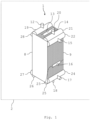
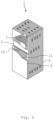
- the Fig. 1 and 2 each show a schematic perspective view of an embodiment of a plate heat exchanger or plate heat exchanger 1.
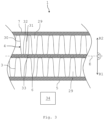
- the Fig. 3 shows a schematic partial sectional view of the plate heat exchanger 1. The following is the Fig. 1 to 3 simultaneously referred to.
- the plate heat exchanger 1 is in particular a plate fin heat exchanger (PFHE) or can be referred to as such.
- the plate heat exchanger 1 can be part of a process plant 2.
- the process plant 2 can be, for example, a plant for air separation, for producing liquefied natural gas (LNG), a plant used in the petrochemical industry or the like.
- the process plant 2 can comprise a plurality of such plate heat exchangers 1.
- the plate heat exchanger 1 is cuboid-shaped or block-shaped and comprises a large number of fins 3, 4 ( Fig. 3 ) and a large number of separating plates 5 to 7.
- the slats 3, 4 are so-called fins, in particular heat transfer fins, or can be referred to as fins.
- the slats 3, 4 can be designed as corrugated or ribbed sheets, for example as aluminum sheets or steel sheets, in particular as stainless steel sheets.
- the separating plates 5 to 7 are separating plates or can be referred to as separating plates.
- the separating plates 5 to 7 can be made of aluminum or steel, in particular stainless steel, for example.
- the number of slats 3, 4 and separating plates 5 to 7 is arbitrary.
- the plate heat exchanger 1 further comprises cover plates 8, 9, between which the plurality of fins 3, 4 and the plurality of separating plates 5 to 7 are arranged.
- the cover plates 8, 9 can be constructed identically to the separating plates 5 to 7.
- the plate heat exchanger 1 also includes so-called sidebars or edge strips 10, 11, which laterally delimit the fins 3, 4.
- the edge strips 10, 11 can be connected to the separating plates 5 to 7 and/or the fins 3, 4 in a material-locking manner, for example soldered or welded.
- material-locking connections the connection partners are held together by atomic or molecular forces.
- Material-locking connections are non-detachable connections that can only be separated by destroying the connecting means.
- the plate heat exchanger 1 forms a large number of parallel heat transfer passages in which process media can flow and indirectly transfer heat to process media guided in adjacent heat transfer passages.
- the individual heat transfer passages can each be supplied with a flow of a process medium using nozzles 12 to 18 and so-called headers 19 to 28.
- the headers 19 to 28 can be referred to as distributors or are distributors.
- the slats 3, 4 and the separating plates 5 to 7 are arranged alternately. This means that between two slats 3, 4 there is a separating plate 5 to 7 and between two separating plates 5 to 7 there is a slat 3, 4.
- the slats 3, 4 and the separating plates 5 to 7 can be connected to one another in a material-locking manner.
- the fins 3, 4 and the separating plates 5 to 7 can be soldered or welded to one another.
- the number of fins 3, 4 and the number of separating plates 5 to 7 is, as previously mentioned, arbitrary.
- the cover plates 8, 9 are positioned on the outside on an outermost fin 3, 4 and thus close the plate heat exchanger 1 in the orientation of the Fig.
- slats 3, 4 are constructed identically.
- Each partition plate 5 to 7 spans a plane E.
- a plane E associated with the separating plate 6 is shown.
- the plane E runs perpendicular to a drawing plane of the Fig. 3 centrally through the separating plate 6.
- the plane E in turn is assigned a first direction R1, which is oriented perpendicular to the plane E, and a second direction R2, which is also oriented perpendicular to the plane E.
- "perpendicular" is to be understood as an angle of 90° ⁇ 10°, more preferably 90° ⁇ 5°, more preferably 90° ⁇ 1°, more preferably exactly 90°.
- the directions R1, R2 are oriented away from the plane E and in opposite directions to each other. In the orientation of the Fig. 3 the first direction R1 is oriented downwards and the second direction R2 is oriented upwards. Conversely, however, the first direction R1 can also be oriented upwards and the second direction R2 downwards.
- the fins 3, 4 have a corrugated geometry so that a plurality of parallel channels 29 are formed.
- a process medium as mentioned above can flow in the channels 29 of the first fin 3, which can then enter into indirect heat exchange with a process medium guided in a parallel fin 3, 4, in this case the second fin 4.
- the channels 29 of adjacent fins 3, 4 can be oriented parallel to one another, obliquely to one another or perpendicular to one another.
- each slat 3, 4 has a plurality of legs 30, 31 arranged parallel to one another, which extend in particular perpendicular to the separating plates 5 to 7. Furthermore, the slats 3, 4 each comprise second legs 32, 33, which are positioned parallel to one another and which support the first legs 30, 31 in the orientation of the Fig. 3 alternately at the top and bottom.
- the legs 30 to 33 can be rounded to one another, resulting in the corrugated geometry. Alternatively, the legs 30 to 33 can also be connected to one another without rounding, resulting in a stepped geometry of the slats 3, 4.
- a plate heat exchanger 1 as previously explained can be sensitive to thermal stresses. These thermal stresses can be caused by different temperatures of the process media involved in the heat exchange. Thermal stresses can lead to mechanical damage to the plate heat exchanger 1 and in particular to leaks between the individual heat transfer passages and even to leaks to the surroundings of the plate heat exchanger 1. For this reason, a measuring device 34 is provided which is designed to measure or record a temporal progression of the temperature distribution and/or an expansion distribution within the plate heat exchanger 1, in particular in a spatially resolved manner.
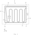
- the measuring device 34 comprises an optical fiber 35 ( Fig. 4 ).
- the optical fiber 35 is in particular a fiber optic sensor cable.
- the optical waveguide 35 (in the Fig. 4 shown in dashed lines) is embedded in the separating plate 6.
- the separating plates 5, 7 can also, but do not have to, comprise such an optical waveguide 35. This means that the separating plates 5 to 7 can be constructed identically. However, only the separating plate 6 will be discussed below.
- the separating plate 6 can comprise a first separating plate section 36 and a second separating plate section 37.
- the optical waveguide 35 is arranged between the first separating plate section 36 and the second separating plate section 37.
- the separating plate sections 36, 37 are in the form of a sheet metal.
- the separating plate 6 thus has a thickness d6 of approximately 1.4 mm.
- the optical waveguide 35 itself can have a diameter d35 of approximately 125 ⁇ m.
- the first separating plate section 36 has a thickness d36 and the second separating plate section 37 has a thickness d37.
- the thicknesses d36, d37 can be the same or different.
- the thickness d36 is greater than the thickness d37.
- the plane E preferably runs centrally through the separating plate 6.
- a groove 38 is provided in which the optical waveguide 35 is accommodated.
- the groove 38 can, as in the Fig. 5 shown, be rectangular in cross-section. However, the groove 38 can have any geometry.
- the groove 38 has a depth t38.
- the depth t38 can be, for example, 0.2 mm.
- the groove 38 is, as shown in the Fig. 4 shown, is designed in a zigzag or meander shape and runs through at least one of the separating plate sections 36, 37.
- the separating plate 6 comprises four side edges 39 to 42, whereby the groove 38 runs into and out of the respective separating plate section 36, 37 only at one of the side edges 39 to 42, namely at the side edge 40. This means that the optical waveguide 35 is led into and out of the separating plate 6 at the side edge 40.
- the separating plate 6 comprises an x-direction or Width direction x, a y-direction or depth direction y oriented perpendicular to the width direction x, and a z-direction or thickness direction z oriented both perpendicular to the width direction x and perpendicular to the depth direction y.
- the directions x, y, z form a coordinate system of the partition plate 6.
- the thicknesses d6, d36, d37 and the depth t38 are measured in the thickness direction z.
- the thickness direction z can correspond to the second direction R2.
- the side edges 39, 41 run in the width direction x, and the side edges 40, 42 run in the depth direction y.
- the plane E is spanned in particular by the width direction x and the depth direction y of the partition plate 6.
- the thickness direction z is oriented perpendicular to the plane E, like the directions R1, R2.
- the first separating plate section 36 and the second separating plate section 37 are materially connected to one another using a solder 43.
- the solder 43 is provided flat between the first separating plate section 36 and the second separating plate section 37.
- the solder 43 can also fill a cavity formed by the groove 38 between the separating plate sections 36, 37.
- the optical waveguide 35 can also have a sleeve 44 in which the optical waveguide 35 is accommodated.
- the optical waveguide 35 is slidably accommodated in the sleeve 44.
- the sleeve 44 can be made of a metal, for example.
- the optical waveguide 35 is now embedded in the separating plate 6 in such a way that the optical waveguide 35 is covered on two sides or both sides by the material of the separating plate 6 when viewed in both directions R1, R2.
- the first partition plate section 36 covers or conceals the optical waveguide 35 in the orientation of the Fig. 5 looking from below at the separating plate 6, the optical waveguide 35 is covered, and the second separating plate section 37 covers the optical waveguide 35 looking from above at the separating plate 6.
- the optical waveguide 35 is covered both in the direction R1 of the first lamella 3 and in the direction R2 of the second lamella 4 by material of the separating plate 6, i.e. by the two separating plate sections 36, 37 ( Fig. 3 ).
- the partition plate 6 can be called an intelligent partition plate due to the embedded optical fiber 35.
- the measuring device 34 is now suitable for detecting or measuring a temperature distribution and/or a strain distribution in the separating plate 6, in particular in a spatially resolved manner, using the embedded optical waveguide 35.
- the temperature measurement can be carried out by evaluating optical signals such as those generated by Raman scattering.
- An optical waveguide 35 as previously explained is usually made of doped quartz glass (amorphous solid structure made mainly of silicon dioxide). Lattice vibrations are induced in these amorphous solid structures via thermal effects. These lattice vibrations are temperature-dependent. Light that hits the molecules in the optical waveguide 35 interacts with the electrons of the molecules. These interactions are called Raman scattering. The backscattered light can be divided into three spectral groups.
- the so-called Stokes and anti-Stokes components In addition to the Rayleigh scattering, which corresponds to the wavelength of the incident light, there are the so-called Stokes and anti-Stokes components. In contrast to the Stokes components, which are shifted to higher wavelengths and are temperature-independent, the anti-Stokes components, which are shifted to smaller wavelengths, are temperature-dependent. An intensity ratio between Stokes and anti-Stokes components can thus be used to measure temperature. A Fourier transformation of these two backscattered components in comparison with a Fourier transformation of a reference signal gives the intensity of the two components over the length of the optical waveguide 35. Thus, the temperature for each point on the optical waveguide 35 can be determined by comparing the two intensities.
- the temperature measurement can be carried out by evaluating optical signals such as those generated by Brillouin scattering of the optical waveguide 35.
- the temperature measurement is based on the spatially resolved determination of a difference frequency between a primary light wave coupled into the optical waveguide 35 and a wave induced and scattered back by it as a result of Brillouin scattering in the optical waveguide 35, the frequency of which is reduced compared to the primary light wave depending on the temperature.
- the frequency shift due to the temperature change can be determined spatially resolved by time-resolved detection of the signal light for various frequency differences and knowledge of the pulse transit time.
- the temperature at any point on the optical waveguide 35 can be determined by evaluating the optical signals.
- the temperature measurement can be carried out by evaluating optical signals, such as those generated by scattering on a Bragg grating.
- Bragg gratings are optical band filters inscribed in the optical waveguide 35, which can be placed in the optical waveguide 35 almost as often as desired.
- a center wave number of a band stop results from the so-called Bragg condition.
- a spectral width of the band stop depends on the grating length and the refractive index as well as the temperature.
- the Fig. 6 and 7 show a further embodiment of a separating plate 6.
- the separating plate 6 comprises a first separating plate section 36 as previously explained and a second separating plate section 37, between which the optical waveguide 35 is arranged.
- the optical waveguide 35 can in turn have the previously explained sleeve 44 (in the Fig. 7 not shown).
- the first separating plate section 36 and the second separating plate section 37 are materially connected to one another by means of a solder 43, wherein the optical waveguide 35 or the sleeve 44 is embedded directly in the solder 43.
- a support structure or a spacer 45 can be provided between the first separating plate section 36 and the second separating plate section 37, which prevents damage to the optical waveguide 35 when mounting the separating plate 6.
- the spacer 45 has a thickness d45 that is greater than the diameter d35 ( Fig. 5 ) of the optical waveguide 35.
- the spacer 45 can be a steel strip.
- the spacer 45 is embedded in the solder 43.
- the spacer 45 also determines a thickness d43 of the solder 43.
- the thickness d45 can be, for example, 170 ⁇ m. This means that the thickness d43 of the solder 43 can also be 170 ⁇ m.
- the Fig. 8 and 9 show a further embodiment of a separating plate 6.
- the separating plate 6 does not comprise two separate separating plate sections 36, 37 that are connected to one another using a solder 43. Rather, two separating plate sections 36, 37 that are connected to one another in one piece, in particular in one piece, are provided. This means that the separating plate sections 36, 37 are made entirely of the same material and are thus inseparably connected to one another.
- the optical waveguide 35 is completely surrounded by the material of the separating plate 6.
- the separating plate 6 is formed in one piece, in particular in one piece.
- the separating plate 6 is manufactured using an additive or generative manufacturing process.
- a powder-based generative manufacturing process in particular a 3D printing process, can be used.
- the separating plate 6 is constructed from a powdery material. This powdery material can, for example, be melted layer by layer using a laser beam to form the separating plate 6.
- SLM selective laser melting
- SLS selective laser sintering
- the fact that the separating plate 6 is manufactured using a generative manufacturing process can be proven microscopically by a layer-by-layer or layer-by-layer construction of the separating plate 6.
- a channel 46 is formed in the separating plate 6, in which the optical waveguide 35 is accommodated.
- the optical waveguide 35 can in turn, as previously mentioned, be accommodated in a sleeve 44.
- the separating plate 6 can, for example, be manufactured in such a way that the manufacturing process for producing the separating plate 6 is carried out in such a way that first a Fig. 9 lower part of the partition plate 6, namely the first partition plate section 36, is manufactured up to a dividing line 47.
- the channel 46 for the optical waveguide 35 is then provided in the first partition plate section 36.
- the optical waveguide 35 is then placed in the channel 46 and this is closed with the aid of the manufacturing process by producing the second partition plate section 37.
- the integral partition plate 6 manufactured in this way can then be provided with a solder layer, for example, and integrated into a conventional manufacturing process for producing a plate heat exchanger 1 as previously explained.
- separating plate 6 With the aid of the previously mentioned separating plate 6, a high-resolution and precise measurement of the temperature and/or the expansion can be carried out on or in the separating plate 6 itself. No additional or only a small amount of additional installation space is required. There can be no undesirable influence on the measured temperature by environmental influences, since the separating plate 6 is positioned within the plate heat exchanger 1. Both expansion and temperature measurements are possible.
- different fiber types can be selected for the optical fiber 35.
- Several, in particular different, optical fibers 35 can also be provided in the separating plate 6.
- an increase in component safety against failure or against leaks to the inside and outside can thus be achieved.
- the availability of the separating plate 6 is increased. Channels provided in the separating plate 6 (not shown) can also be used to take material samples, provided they are connected to the corresponding heat transfer passage.
- the Fig. 10 shows a schematic block diagram of an embodiment of a method for producing a plate heat exchanger 1 as explained above.
- a step S1 a plurality of fins 3, 4 are provided.
- undeformed raw sheets can be formed into the corrugated or stepped fins 3, 4.
- a step S2 a plurality of separating plates 5 to 7 are provided.
- a step S3 at least one optical waveguide 35 is provided.
- the optical waveguide 35 is embedded in at least one of the separating plates 5 to 7, namely, for example, in the separating plate 6, such that the optical waveguide 35 is covered on two sides or both sides by material of the at least one separating plate 6, viewed in both the first direction R1 and the second direction R2.
- the slats 3, 4 and the separating plates 5 to 7 can then be alternately arranged to form the plate heat exchanger 1.
- the fins 3, 4 and the separating plates 5 to 7 can be soldered or welded together.
- the optical waveguide 35 can be embedded by arranging the optical waveguide 35 between the first separating plate section 36 and the second separating plate section 37.
- the two separating plate sections 36, 37 can be connected to one another in a material-locking manner using the solder 43.
- the optical waveguide 35 can either be embedded in the solder 43, or the optical waveguide is inserted into the groove 38 provided on at least one of the separating plate sections 36, 37 before the two separating plate sections 36, 37 are soldered or welded.
- the separating plate 6 can also be built up around the optical waveguide 35 using a generative manufacturing process.
Landscapes
- Engineering & Computer Science (AREA)
- Physics & Mathematics (AREA)
- Thermal Sciences (AREA)
- Mechanical Engineering (AREA)
- General Engineering & Computer Science (AREA)
- General Physics & Mathematics (AREA)
- Heat-Exchange Devices With Radiators And Conduit Assemblies (AREA)
- Optical Couplings Of Light Guides (AREA)
Description
- Die Erfindung betrifft einen Plattenwärmetauscher für eine verfahrenstechnische Anlage, eine verfahrenstechnische Anlage mit einem derartigen Plattenwärmetauscher und ein Verfahren zum Herstellen eines derartigen Plattenwärmetauschers.
- Sogenannte Plattenwärmetauscher umfassen eine Vielzahl an Lamellen oder Fins, zwischen denen Trennbleche angeordnet sind. Die Trennbleche trennen benachbarte Wärmeübertragungspassagen derart voneinander, dass ein stofflicher Übergang zwischen den Wärmeübertragungspassagen verhindert, jedoch ein Wärmeübergang ermöglicht wird. Thermische Spannungen infolge unterschiedlicher Wärmedehnungen aus differentiellen Temperaturunterschieden können jedoch zur mechanischen Schädigung der Dichtheit zwischen den Wärmeübertragungspassagen bis hin zur Undichtigkeit des Plattenwärmetauschers gegenüber seiner Umgebung führen. Zur Analyse des Temperaturfeldes kann ein derartiger Plattenwärmetauscher beispielsweise mit einer Temperaturmessung auf einer Oberfläche seiner Außenhaut ausgestattet sein. Die Temperaturen auf der Außenhaut liefern jedoch nur einen lokalen Wert, mit dem unter Annahmen auf die Temperatur im Inneren des Plattenwärmetauschers zurückgeschlossen werden kann. Diese Temperaturmessungen können jedoch aufgrund der Messung an der Außenhaut von Umwelteinflüssen beeinflusst werden.
- Die
WO 2014/056587 A1 beschreibt einen Plattenwärmetauscher mit einem Lichtwellenleiter zur Temperaturmessung. Der Lichtwellenleiter ist dabei in einer offenen Nut positioniert, die entweder in einer Lamelle oder in einem Trennblech des Plattenwärmetauschers vorgesehen ist. - Vor diesem Hintergrund besteht eine Aufgabe der vorliegenden Erfindung darin, einen verbesserten Wärmetauscher zur Verfügung zu stellen.
- Demgemäß wird ein Plattenwärmetauscher für eine verfahrenstechnische Anlage gemäß Patent anspruch 1 vorgeschlagen.
- Dadurch, dass der Lichtwellenleiter innerhalb der Trennplatte angeordnet ist, kann zum einen eine Beschädigung des Lichtwellenleiters verhindert werden. Zum anderen ist eine hochauflösende und exakte Messung der Temperatur direkt in der Trennplatte und somit auch im Inneren des Plattenwärmetauschers möglich. Dadurch, dass der Lichtwellenleiter in die Trennplatte integriert ist, ist kein zusätzlicher oder zumindest nur ein geringfügiger zusätzlicher Bauraum zur Erfassung der Temperaturverteilung und/oder Dehnungsverteilung erforderlich. Da die Trennplatte innerhalb des Plattenwärmetauschers angeordnet ist, ergibt sich keine Beeinflussung der gemessenen Temperatur durch Umgebungseinflüsse. Mit Hilfe des Lichtwellenleiters können sowohl Dehnungsmessungen als auch Temperaturmessungen durchgeführt werden. Die Erhöhung der Bauteilsicherheit gegen Versagen oder Leckagen nach innen oder nach außen wird erhöht.
- Darunter, dass die Lamellen und die Trennplatten "abwechselnd" angeordnet sind, ist zu verstehen, dass zwischen zwei Lamellen eine Trennplatte und zwischen zwei Trennplatten eine Lamelle angeordnet ist. Die Anzahl der Lamellen und die Anzahl der Trennplatten ist grundsätzlich beliebig. Die Lamellen und die Trennplatten sind insbesondere zwischen zwei Deckplatten des Plattenwärmetauschers positioniert. Von den Lamellen gebildete Schichten, sogenannte Lamellenschichten, formen sogenannte Passagen, insbesondere Wärmeübertragungspassagen, die durch Randleisten oder Sidebars zur Umgebung abgetrennt sind. Der Lichtwellenleiter ist vorzugsweise ein Glasfaser-Sensorkabel. Der Lichtwellenleiter kann somit ein Sensorelement einer Messeinrichtung des Plattenwärmetauschers sein. Dass der Lichtwellenleiter in die zumindest eine Trennplatte "eingebettet" ist, bedeutet, dass der Lichtwellenleiter vollständig innerhalb der Trennplatte angeordnet ist. Die von der zumindest einen Trennplatte aufgespannte Ebene verläuft vorzugsweise derart mittig durch die zumindest eine Trennplatte, dass diese bezüglich der Ebene bevorzugt spiegelsymmetrisch aufgebaut ist.
- Die zumindest eine Trennplatte weist vorzugsweise eine rechteckförmige Geometrie auf, wobei die Trennplatte eine Dicke von etwa 1 bis 2 mm aufweisen kann. Damit ist die zumindest eine Trennplatte nicht oder nur geringfügig dicker als eine Trennplatte ohne einen derartigen Lichtwellenleiter. Die Trennplatten können als Trennbleche bezeichnet werden. Die Lamellen können als Fins bezeichnet werden. Es können mehrere Trennplatten mit einem derartigen Lichtwellenleiter versehen sein. Die zumindest eine Trennplatte umfasst bevorzugt zumindest einen Lichtwellenleiter. Ferner kann die zumindest eine Trennplatte mehrere, insbesondere unterschiedliche, Lichtwellenleiter umfassen. Die Lamellen können eine gewellte oder gestufte Geometrie aufweisen. Aufgrund des eingebetteten Lichtwellenleiters kann die zumindest eine Trennplatte als intelligente Trennplatte bezeichnet werden.
- Die von der Trennplatte aufgespannte Ebene ist eine Haupterstreckungsebene der Trennplatte. Das heißt, die Trennplatte erstreckt sich blechförmig oder plattenförmig in der Ebene. Die Ebene wird insbesondere von einer Breitenrichtung und einer Tiefenrichtung der Trennplatte aufgespannt. Die Ebene wird insbesondere nicht von einer Dickenrichtung der Trennplatte aufgespannt. Die Dickenrichtung ist vielmehr senkrecht zu der Ebene orientiert. Unter "senkrecht" ist vorliegend ein Winkel von 90° ± 10°, weiter bevorzugt von 90° ± 5°, weiter bevorzugt von 90° ± 1°, weiter bevorzugt von genau 90° zu verstehen. Die Breitenrichtung, die Tiefenrichtung und die Dickenrichtung bilden ein Koordinatensystem der zumindest einen Trennplatte. Die Dickenrichtung kann dabei mit einer der zu der Ebene senkrecht positionierten Richtungen übereinstimmen. Das heißt, der Lichtwellenleiter ist insbesondere in der Dickenrichtung der Trennplatte zweiseitig oder beidseitig von dem Material der Trennplatte abgedeckt oder verdeckt.
- Darunter, dass der Lichtwellenleiter "beidseitig" oder "zweiseitig" von dem Material der Trennplatte abgedeckt ist, ist zu verstehen, dass sowohl in der ersten Richtung betrachtet als auch in der zweiten Richtung betrachtet der Lichtwellenleiter insbesondere sowohl oberseitig als auch unterseitig von dem Material der Trennplatte bedeckt oder abgedeckt ist. Darunter, dass die erste Richtung und die zweite Richtung "gegensinnig" orientiert sind, ist zu verstehen, dass die beiden Richtungen voneinander weg weisen. Insbesondere ist die erste Richtung parallel zu der zweiten Richtung orientiert. Die beiden Richtungen sind insbesondere in einem Winkel von 180° zueinander positioniert.
- Gemäß einer Ausführungsform umfasst der Plattenwärmetauscher eine erste Lamelle und eine zweite Lamelle, wobei die zumindest eine Trennplatte zwischen der ersten Lamelle und der zweiten Lamelle angeordnet ist, und wobei der Lichtwellenleiter derart in die zumindest eine Trennplatte eingebettet ist, dass der Lichtwellenleiter sowohl in Richtung der ersten Lamelle als auch in Richtung der zweiten Lamelle von dem Material der zumindest einen Trennplatte abgedeckt ist.
- Die Anzahl der Lamellen ist, wie zuvor erwähnt, beliebig. Dabei ist jeweils zwischen zwei Lamellen eine Trennplatte und umgekehrt angeordnet. Dass der Lichtwellenleiter sowohl in Richtung der ersten Lamelle als auch in Richtung der zweiten Lamelle von dem Material der zumindest einen Trennplatte abgedeckt ist, bedeutet, dass die Trennplatte sowohl zwischen der ersten Lamelle und dem Lichtwellenleiter als auch zwischen der zweiten Lamelle und dem Lichtwellenleiter angeordnet ist. Das heißt, der Lichtwellenleiter gerät nicht in direkten Kontakt mit einer der Lamellen.
- Erfindungsgemäß weist die zumindest eine Trennplatte einen ersten Trennplattenabschnitt und einen zweiten Trennplattenabschnitt auf, zwischen denen der Lichtwellenleiter angeordnet ist.
- Der erste Trennplattenabschnitt und der zweite Trennplattenabschnitt können jeweils als Bleche, insbesondere als Aluminiumbleche oder Stahlbleche, ausgebildet sein. Beispielsweise weisen der erste Trennplattenabschnitt und der zweite Trennplattenabschnitt eine identische Dicke oder unterschiedliche Dicken auf. Beispielsweise ist der erste Trennplattenabschnitt zwischen dem Lichtwellenleiter und der ersten Lamelle und der zweite Trennplattenabschnitt ist zwischen dem Lichtwellenleiter und der zweiten Lamelle oder umgekehrt positioniert.
- Erfingungsgemäß sind der erste Trennplattenabschnitt und der zweite Trennplattenabschnitt mit Hilfe eines Lots stoffschlüssig miteinander verbunden.
- Bei stoffschlüssigen Verbindungen werden die Verbindungspartner durch atomare oder molekulare Kräfte zusammengehalten. Stoffschlüssige Verbindungen sind nicht lösbare Verbindungen, die sich nur durch Zerstörung der Verbindungsmittel, in diesem Fall dem Lot, oder der Verbindungspartner, in diesem Fall der Trennplattenabschnitte, voneinander lösen lassen. Die Trennplattenabschnitte können auch miteinander verschweißt sein.
- Gemäß einer weiteren Ausführungsform ist der Lichtwellenleiter in das Lot eingebettet.
- Erfindungsgemäß weist der erste Trennplattenabschnitt und der zweite Trennplattenabschnitt eine Nut auf, in der der Lichtwellenleiter angeordnet ist.
- Die Nut kann einen Hohlraum innerhalb der zumindest einen Trennplatte bilden. Der Lichtwellenleiter kann frei beweglich in der Nut aufgenommen sein. Alternativ kann die Nut auch mit dem Lot gefüllt sein, so dass die Lichtwellenleiter in das Lot eingebettet ist. Die Nut kann gerade, zickzackförmig oder mäanderförmig durch die zumindest eine Trennplatte hindurchlaufen.
- Gemäß einer weiteren Ausführungsform ist der Lichtwellenleiter in einer Hülse aufgenommen.
- Die Hülse ist vorzugsweise eine Metallhülse. Die Hülse kann in das Lot eingebettet sein. Der Lichtwellenleiter ist bevorzugt linear axial verschiebbar in der Hülse aufgenommen.
- Ferner wird eine verfahrenstechnische Anlage mit einem derartigen Plattenwärmetauscher vorgeschlagen.
- Die verfahrenstechnische Anlage kann beispielsweise eine Anlage zur Luftzerlegung, zur Flüssiggaserzeugung oder eine in der petrochemischen Industrie eingesetzte Anlage sein. Die verfahrenstechnische Anlage kann eine Vielzahl derartiger Plattenwärmetauscher umfassen.
- Weiterhin wird ein Verfahren zum Herstellen eines Plattenwärmetauschers für eine verfahrenstechnische Anlage gemäß Patentanspruch 6 vorgeschlagen.
- In dem Schritt c) wird insbesondere zumindest ein Lichtwellenleiter bereitgestellt. Es können jedoch auch mehrere, insbesondere auch unterschiedliche, Lichtwellenleiter bereitgestellt werden. Der Schritt d) kann alternativ auch ein Einbetten der zuvor erwähnten Hülse umfassen, derart, dass die Hülse in der ersten Richtung und in der zweiten Richtung beidseitig von Material der zumindest einen Trennplatte abgedeckt wird. Die Hülse kann auch zusammen mit dem Lichtwellenleiter eingebettet werden. In diesem Fall wird der Lichtwellenleiter vor dem Einbetten desselben in die Hülse eingeführt. Alternativ kann der Lichtwellenleiter auch nach dem Einbetten der Hülse in diese eingeführt werden. Die Schritte a) bis e) müssen nicht in der alphabetischen Reihenfolge durchgeführt werden. Beispielsweise kann das Einbetten des insbesondere zumindest einen Lichtwellenleiters oder auch der Hülse in die zumindest eine Trennplatte bereits in dem Schritt b), nämlich bei dem Bereitstellen der Vielzahl an Trennplatten erfolgen. Es kann eine Vielzahl an Trennplatten vorgesehen sein, in die jeweils ein Lichtwellenleiter oder eine Hülse eingebettet wird. Bevorzugt ist jedochzumindest eine derartige Trennplatte vorgesehen.
- Gemäß einer Ausführungsform wird in dem Schritt d) der Lichtwellenleiter zwischen einem ersten Trennplattenabschnitt und einem zweiten Trennplattenabschnitt der zumindest einen Trennplatte angeordnet.
- In den senkrecht zu der von der zumindest einen Trennplatte aufgespannten Ebene orientierten Richtungen decken der erste Trennplattenabschnitt und der zweite Trennplattenabschnitt den Lichtwellenleiter zweiseitig oder beidseitig ab, so dass dieser in den beiden Richtungen betrachtet beidseitig von dem Material der Trennplatte abgedeckt oder verdeckt ist.
- Erfindungsgemäß werden in dem Schritt d) der erste Trennplattenabschnitt und der zweite Trennplattenabschnitt mit Hilfe eines Lots stoffschlüssig miteinander verbunden.
- Hierbei kann der Lichtwellenleiter oder die Hülse, in der der Lichtwellenleiter aufgenommen ist, in das Lot eingebettet werden. Die Trennplattenabschnitte können auch miteinander verschweißt werden.
- Gemäß einer weiteren Ausführungsform wird in dem Schritt d) der Lichtwellenleiter oder eine Hülse, in der der Lichtwellenleiter aufnehmbar ist, in einer Nut, die der erste Trennplattenabschnitt und der zweite Trennplattenabschnitt aufweist, angeordnet.
- Die Nut kann mit dem Lot aufgefüllt sein. Die Nut kann auch lotfrei sein, so dass der Lichtwellenleiter in der Nut beweglich ist. Die Nut kann rechteckförmig sein. Die Nut kann aber auch jede andere Geometrie aufweisen.
- Weitere mögliche Implementierungen des Plattenwärmetauschers, der verfahrenstechnischen Anlage und/oder des Verfahrens umfassen auch nicht explizit genannte Kombinationen von zuvor oder im Folgenden bezüglich der Ausführungsbeispiele beschriebenen Merkmalen oder Ausführungsformen. Dabei wird der Fachmann auch Einzelaspekte als Verbesserungen oder Ergänzungen zu der jeweiligen Grundform des Plattenwärmetauschers, der verfahrenstechnischen Anlage und/oder des Verfahrens hinzufügen.
- Weitere vorteilhafte Ausgestaltungen und Aspekte des Plattenwärmetauschers, der verfahrenstechnischen Anlage und/oder des Verfahrens sind Gegenstand der Unteransprüche sowie der im Folgenden beschriebenen Ausführungsbeispiele des Plattenwärmetauschers, der verfahrenstechnischen Anlage und/oder des Verfahrens. Im Weiteren werden der Plattenwärmetauscher, die verfahrenstechnische Anlage und/oder das Verfahren anhand von bevorzugten Ausführungsformen unter Bezugnahme auf die beigelegten Figuren näher erläutert.
-
Fig. 1 zeigt eine schematische perspektivische Ansicht einer Ausführungsform eines Plattenwärmetauschers; -
Fig. 2 zeigt eine weitere schematische perspektivische Ansicht des Plattenwärmetauschers gemäßFig. 1 ; -
Fig. 3 zeigt eine schematische Teilschnittansicht des Plattenwärmetauschers gemäßFig. 1 ; -
Fig. 4 zeigt eine schematische Ansicht einer Ausführungsform einer Trennplatte für den Plattenwärmetauscher gemäßFig. 1 ; -
Fig. 5 zeigt eine Trennplatte 6, die keine Ausführungform der vorliegenden Erfindung darstellt -
Fig. 6 zeigt eine Trennplatte 6, die keine Ausführungform der vorliegenden Erfindung darstellt -
Fig. 7 zeigt eine Trennplatte 6, die keine Ausführungform der vorliegenden Erfindung darstellt -
Fig. 8 zeigt eine Trennplatte 6, die keine Ausführungform der vorliegenden Erfindung darstellt -
Fig. 9 zeigt eine Trennplatte 6, die keine Ausführungform der vorliegenden Erfindung darstellt -
Fig. 10 zeigt ein schematisches Blockdiagramm einer Ausführungsform eines Verfahrens zum Herstellen des Plattenwärmetauschers gemäßFig. 1 . - In den Figuren sind gleiche oder funktionsgleiche Elemente mit denselben Bezugszeichen versehen worden, sofern nichts anderes angegeben ist.
- Die
Fig. 1 und2 zeigen jeweils eine schematische perspektivische Ansicht einer Ausführungsform eines Plattenwärmeübertragers oder Plattenwärmetauschers 1. DieFig. 3 zeigt eine schematische Teilschnittansicht des Plattenwärmetauschers 1. Nachfolgend wird auf dieFig. 1 bis 3 gleichzeitig Bezug genommen. - Der Plattenwärmetauscher 1 ist insbesondere ein Plate Fin Heat Exchanger (PFHE) oder kann als solcher bezeichnet werden. Der Plattenwärmetauscher 1 kann Teil einer verfahrenstechnischen Anlage 2 sein. Die verfahrenstechnische Anlage 2 kann beispielsweise eine Anlage zur Luftzerlegung, zur Herstellung von Flüssiggas (Engl.: Liquefied Natural Gas, LNG), eine in der petrochemischen Industrie eingesetzte Anlage oder dergleichen sein. Die verfahrenstechnische Anlage 2 kann eine Vielzahl derartiger Plattenwärmetauscher 1 umfassen.
- Der Plattenwärmetauscher 1 ist quaderförmig oder blockförmig aufgebaut und umfasst eine Vielzahl an Lamellen 3, 4 (
Fig. 3 ) sowie eine Vielzahl an Trennplatten 5 bis 7. Die Lamellen 3, 4 sind so genannte Fins, insbesondere Heat Transfer Fins, oder können als Fins bezeichnet werden. Die Lamellen 3, 4 können als gewellte oder gerippte Bleche, beispielsweise als Aluminiumbleche oder Stahlbleche, insbesondere als Edelstahlbleche, ausgebildet sein. Die Trennplatten 5 bis 7 sind Trennbleche oder können als Trennbleche bezeichnet werden. Die Trennplatten 5 bis 7 können beispielsweise aus Aluminium oder Stahl, insbesondere aus Edelstahl, gefertigt sein. Die Anzahl der Lamellen 3, 4 und Trennplatten 5 bis 7 ist beliebig. - Der Plattenwärmetauscher 1 umfasst weiterhin Deckplatten 8, 9, zwischen denen die Vielzahl an Lamellen 3, 4 und die Vielzahl an Trennplatten 5 bis 7 angeordnet sind. Die Deckplatten 8, 9 können dabei identisch wie die Trennplatten 5 bis 7 aufgebaut sein.
- Weiterhin umfasst der Plattenwärmetauscher 1 sogenannten Sidebars oder Randleisten 10, 11, die die Lamellen 3, 4 seitlich begrenzen. Die Randleisten 10, 11 können mit den Trennplatten 5 bis 7 und/oder den Lamellen 3, 4 stoffschlüssig verbunden, beispielsweise verlötet oder verschweißt, sein. Bei stoffschlüssigen Verbindungen werden die Verbindungspartner durch atomare oder molekulare Kräfte zusammengehalten. Stoffschlüssige Verbindungen sind nicht lösbare Verbindungen, die sich nur durch Zerstörung der Verbindungsmittel trennen lassen.
- Mit Hilfe der Lamellen 3, 4 und der Trennplatten 5 bis 7 bildet der Plattenwärmetauscher 1 eine Vielzahl an parallelen Wärmeübertragungspassagen aus, in denen Prozessmedien strömen können und indirekt Wärme auf in benachbarten Wärmeübertragungspassagen geführte Prozessmedien übertragen können. Die einzelnen Wärmeübertragungspassagen können mit Hilfe von Stutzen 12 bis 18 und sogenannten Headern 19 bis 28 jeweils mit einem Strom eines Prozessmediums beschickt werden. Die Header 19 bis 28 können als Verteiler bezeichnet werden oder sind Verteiler.
- Wie die
Fig. 3 zeigt, sind die Lamellen 3, 4 und die Trennplatten 5 bis 7 abwechselnd angeordnet. Das heißt, zwischen zwei Lamellen 3, 4 ist jeweils eine Trennplatte 5 bis 7 und zwischen zwei Trennplatten 5 bis 7 ist jeweils eine Lamelle 3, 4 positioniert. Die Lamellen 3, 4 und die Trennplatten 5 bis 7 können dabei stoffschlüssig miteinander verbunden sein. Beispielsweise können die Lamellen 3, 4 und die Trennplatten 5 bis 7 miteinander verlötet oder verschweißt sein. Die Anzahl der Lamellen 3, 4 und die Anzahl der Trennplatten 5 bis 7 ist dabei, wie zuvor erwähnt, beliebig. Die Deckplatten 8, 9 sind dabei außenseitig auf einer jeweils äußersten Lamelle 3, 4 positioniert und schließen den Plattenwärmetauscher 1 somit in der Orientierung derFig. 1 und2 nach vorne und hinten ab. In derFig. 3 sind lediglich zwei Lamellen 3, 4, insbesondere eine erste Lamelle 3 sowie eine zweite Lamelle 4, und drei Trennplatten 5 bis 7 gezeigt. Die Lamellen 3, 4 sind identisch aufgebaut. - Jede Trennplatte 5 bis 7 spannt eine Ebene E auf. In der
Fig. 3 ist lediglich eine der Trennplatte 6 zugeordnete Ebene E dargestellt. Die Ebene E verläuft dabei senkrecht zu einer Zeichenebene derFig. 3 mittig durch die Trennplatte 6 hindurch. Der Ebene E wiederum sind eine erste Richtung R1, die senkrecht zu der Ebene E orientiert ist, und eine zweite Richtung R2, die ebenfalls senkrecht zu der Ebene E orientiert ist, zugeordnet. Unter "senkrecht" ist vorliegend ein Winkel von 90° ± 10°, weiter bevorzugt von 90° ± 5°, weiter bevorzugt von 90° ± 1°, weiter bevorzugt von genau 90° zu verstehen. Die Richtungen R1, R2 sind dabei von der Ebene E weg und gegensinnig zueinander orientiert. In der Orientierung derFig. 3 ist die erste Richtung R1 nach unten und die zweite Richtung R2 nach oben orientiert. Umgekehrt kann jedoch auch die erste Richtung R1 nach oben und die zweite Richtung R2 nach unten orientiert sein. - Wie die
Fig. 3 weiterhin zeigt, weisen die Lamellen 3, 4 eine gewellte Geometrie auf, so dass eine Mehrzahl an parallelen Kanälen 29 gebildet wird. In den Kanälen 29 der ersten Lamelle 3 kann ein wie zuvor erwähntes Prozessmedium strömen, das dann in indirekten Wärmeaustausch mit einem in einer parallelen Lamelle 3, 4, in diesem Fall der zweiten Lamelle 4, geführten Prozessmedium treten kann. Die Kanäle 29 benachbarter Lamellen 3, 4 können parallel zueinander, schräg zueinander oder senkrecht zueinander orientiert sein. - Die gewellte Geometrie der Lamellen 3, 4 wird dadurch gebildet, dass jede Lamelle 3, 4 jeweils eine Vielzahl an parallel zueinander angeordneten Schenkeln 30, 31 aufweist, die sich insbesondere senkrecht zu den Trennplatten 5 bis 7 erstrecken. Weiterhin umfassen die Lamellen 3, 4 jeweils zweite Schenkel 32, 33, die parallel zueinander positioniert sind und die die ersten Schenkel 30, 31 in der Orientierung der
Fig. 3 jeweils abwechselnd oben und unten miteinander verbinden. Die Schenkel 30 bis 33 können dabei miteinander verrundet sein, so dass sich die gewellte Geometrie ergibt. Alternativ können die Schenkel 30 bis 33 auch ohne Verrundungen miteinander verbunden sein, so dass sich eine gestufte Geometrie der Lamellen 3, 4 ergibt. - Ein wie zuvor erläuterter Plattenwärmetauscher 1 kann empfindlich in Bezug auf thermische Spannungen sein. Diese thermischen Spannungen können durch unterschiedliche Temperaturen der sich im Wärmeaustausch befindlichen Prozessmedien hervorgerufen werden. Thermische Spannungen können zu mechanischer Schädigung des Plattenwärmetauschers 1 und insbesondere zu Undichtigkeit zwischen den einzelnen Wärmeübertragungspassagen bis hin zu Undichtigkeit gegenüber einer Umgebung des Plattenwärmetauschers 1 führen. Aus diesem Grund ist eine Messeinrichtung 34 vorgesehen, die dazu eingerichtet ist, einen zeitlichen Verlauf der Temperaturverteilung und/oder einer Dehnungsverteilung innerhalb des Plattenwärmetauschers 1, insbesondere ortsaufgelöst, zu messen beziehungsweise zu erfassen. Als Sensorelement umfasst die Messeinrichtung 34 hierbei einen Lichtwellenleiter 35 (
Fig. 4 ). Der Lichtwellenleiter 35 ist insbesondere ein Glasfaser-Sensorkabel. - Wie die
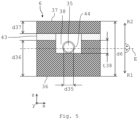
Fig. 4 und5 anhand der Trennplatte 6 zeigen, ist der Lichtwellenleiter 35 (in derFig. 4 gestrichelt dargestellt) in die Trennplatte 6 eingebettet. Auch die Trennplatten 5, 7 können, müssen jedoch nicht, einen derartigen Lichtwellenleiter 35 umfassen. Das heißt, die Trennplatten 5 bis 7 können identisch aufgebaut sein. Nachfolgend wird jedoch nur auf die Trennplatte 6 eingegangen. - Die Trennplatte 6 kann einen ersten Trennplattenabschnitt 36 sowie einen zweiten Trennplattenabschnitt 37 umfassen. Zwischen dem ersten Trennplattenabschnitt 36 und dem zweiten Trennplattenabschnitt 37 ist der Lichtwellenleiter 35 angeordnet. Die Trennplattenabschnitte 36, 37 sind dabei blechförmig ausgebildet. Beispielsweise weist die Trennplatte 6 somit eine Dicke d6 von etwa 1,4 mm auf. Der Lichtwellenleiter 35 selbst kann einen Durchmesser d35 von etwa 125 µm aufweisen. Der erste Trennplattenabschnitt 36 weist eine Dicke d36 auf, und der zweite Trennplattenabschnitt 37 weist eine Dicke d37 auf. Die Dicken d36, d37 können gleich groß oder unterschiedlich groß sein. Beispielsweise ist die Dicke d36 größer als die Dicke d37. Die Ebene E verläuft bevorzugt mittig durch die Trennplatte 6 hindurch.
- In dem ersten Trennplattenabschnitt 36 und/oder in dem zweiten Trennplattenabschnitt 37 ist eine Nut 38 vorgesehen, in der der Lichtwellenleiter 35 aufgenommen ist. Die Nut 38 kann, wie in der
Fig. 5 gezeigt, im Querschnitt rechteckförmig sein. Die Nut 38 kann jedoch jede beliebige Geometrie aufweisen. Die Nut 38 weist eine Tiefe t38 auf. Die Tiefe t38 kann beispielsweise 0,2 mm betragen. Die Nut 38 ist, wie in derFig. 4 gezeigt, zickzackförmig oder mäanderförmig ausgebildet und verläuft durch zumindest einen der Trennplattenabschnitte 36, 37 hindurch. Die Trennplatte 6 umfasst dabei vier Seitenkanten 39 bis 42, wobei die Nut 38 jedoch nur an einer der Seitenkanten 39 bis 42, nämlich an der Seitenkante 40, in den jeweiligen Trennplattenabschnitt 36, 37 hineinläuft und wieder aus diesem herausläuft. Das heißt, der Lichtwellenleiter 35 wird an der Seitenkante 40 in die Trennplatte 6 hinein- und auch wieder aus dieser herausgeführt. - Die Trennplatte 6 umfasst eine x-Richtung oder Breitenrichtung x, eine senkrecht zu der Breitenrichtung x orientierte y-Richtung oder Tiefenrichtung y sowie eine sowohl senkrecht zu der Breitenrichtung x als auch senkrecht zu der Tiefenrichtung y orientierte z-Richtung oder Dickenrichtung z. Die Richtungen x, y, z bilden ein Koordinatensystem der Trennplatte 6. Die Dicken d6, d36, d37 und die Tiefe t38 werden in der Dickenrichtung z gemessen. Die Dickenrichtung z kann mit der zweiten Richtung R2 übereinstimmen. Die Seitenkanten 39, 41 verlaufen in der Breitenrichtung x, und die Seitenkanten 40, 42 verlaufen in der Tiefenrichtung y. Die Ebene E wird insbesondere von der Breitenrichtung x und der Tiefenrichtung y der Trennplatte 6 aufgespannt. Die Dickenrichtung z ist, wie die Richtungen R1, R2, senkrecht zu der Ebene E orientiert.
- Der erste Trennplattenabschnitt 36 und der zweite Trennplattenabschnitt 37 sind mit Hilfe eines Lots 43 stoffschlüssig miteinander verbunden. Das Lot 43 ist dabei flächig zwischen dem ersten Trennplattenabschnitt 36 und dem zweiten Trennplattenabschnitt 37 vorgesehen. Das Lot 43 kann auch einen von der Nut 38 zwischen den Trennplattenabschnitten 36, 37 gebildeten Hohlraum ausfüllen. Der Lichtwellenleiter 35 kann ferner noch eine Hülse 44 aufweisen, in der der Lichtwellenleiter 35 aufgenommen ist. Der Lichtwellenleiter 35 ist verschiebbar in der Hülse 44 aufgenommen. Die Hülse 44 kann beispielsweise aus einem Metall gefertigt sein.
- Der Lichtwellenleiter 35 ist nun derart in die Trennplatte 6 eingebettet, dass der Lichtwellenleiter 35 in beiden Richtungen R1, R2 betrachtet zweiseitig oder beidseitig von Material der Trennplatte 6 abgedeckt ist. Das heißt, in der Orientierung der
Fig. 5 ist der Lichtwellenleiter 35 nach unten hin, das heißt, in der ersten Richtung R1, von dem ersten Trennplattenabschnitt 36 und nach oben hin, das heißt, in der zweiten Richtung R2, von dem zweiten Trennplattenabschnitt 37 abgedeckt oder verdeckt. Mit anderen Worten deckt der erste Trennplattenabschnitt 36 in der Orientierung derFig. 5 mit Blickrichtung von unten auf die Trennplatte 6 den Lichtwellenleiter 35 ab, und der zweite Trennplattenabschnitt 37 deckt den Lichtwellenleiter 35 mit Blickrichtung von oben auf die Trennplatte 6 ab. Insbesondere ist der Lichtwellenleiter 35 sowohl in Richtung R1 der ersten Lamelle 3 als auch in Richtung R2 der zweiten Lamelle 4 von Material der Trennplatte 6, das heißt, von den beiden Trennplattenabschnitten 36, 37 abgedeckt (Fig. 3 ). Die Trennplatte 6 kann aufgrund des eingebetteten Lichtwellenleiters 35 als intelligente Trennplatte bezeichnet werden. - Die Messeinrichtung 34 ist nun geeignet, mit Hilfe des eingebetteten Lichtwellenleiters 35 eine Temperaturverteilung und/oder eine Dehnungsverteilung in der Trennplatte 6, insbesondere ortsaufgelöst, zu erfassen beziehungsweise zu messen. Beispielsweise kann die Temperaturmessung über die Auswertung von optischen Signalen, wie sie durch Raman-Streuung entstehen, erfolgen. Ein wie zuvor erläuterter Lichtwellenleiter 35 wird in der Regel aus dotiertem Quarzglas (amorphe Festkörperstruktur aus hauptsächlich Siliziumdioxid) gefertigt. In diesen amorphen Festkörperstrukturen werden über thermische Effekte Gitterschwingungen induziert. Diese Gitterschwingungen sind temperaturabhängig. Licht, welches auf die Moleküle in dem Lichtwellenleiter 35 trifft, tritt in Wechselwirkung mit den Elektronen der Moleküle. Diese Wechselwirkungen nennt man Raman-Streuung. Das zurückgestreute Licht lässt sich in drei spektrale Gruppen einteilen.
- Neben der Rayleigh-Streuung, welche der Wellenlänge des eingestrahlten Lichts entspricht, existieren die sogenannten Stokes- und die sogenannten Anti-Stokes-Komponenten. Im Gegensatz zu den, zu höheren Wellenlängen verschobenen und temperaturunabhängigen, Stokes-Komponenten sind die zu kleineren Wellenlängen verschobenen Anti-Stokes-Komponenten temperaturabhängig. Ein Intensitätsverhältnis zwischen Stokes- und Anti-Stokes-Komponenten kann somit zur Temperaturmessung genutzt werden. Über eine Fourier-Transformation dieser beiden rückgestreuten Komponenten im Vergleich mit einer Fourier-Transformation eines Referenzsignals erhält man die Intensität der beiden Komponenten über der Länge des Lichtwellenleiters 35. Somit kann über den Vergleich der beiden Intensitäten die Temperatur für jeden Punkt des Lichtwellenleiters 35 ermittelt werden.
- Alternativ kann die Temperaturmessung über die Auswertung von optischen Signalen, wie sie durch Brillouin-Streuung des Lichtwellenleiters 35 entstehen, erfolgen. In diesem Fall basiert die Temperaturmessung auf der ortsaufgelösten Bestimmung einer Differenzfrequenz zwischen einer, in den Lichtwellenleiter 35 eingekoppelten, primären Lichtwelle und einer durch sie infolge von Brillouin-Streuung im Lichtwellenleiter 35 induzierten und zurückgestreuten Welle, welche in ihrer Frequenz in Abhängigkeit von der Temperatur gegenüber der primären Lichtwelle verringert ist. Bei gepulst eingestrahlter primärer Lichtwelle kann durch zeitaufgelöste Detektion des Signallichtes für verschiedene Frequenzdifferenzen und der Kenntnis der Pulslaufzeit die Frequenzverschiebung aufgrund der Temperaturveränderung ortsaufgelöst bestimmt werden. Auch in diesem Fall lässt sich somit durch die Auswertung der optischen Signale die Temperatur an jedem beliebigen Punkt des Lichtwellenleiters 35 bestimmen.
- Weiterhin kann die Temperaturmessung über die Auswertung von optischen Signalen, wie sie durch Streuung an einem Bragg-Gitter entstehen, erfolgen. Bragg-Gitter sind in den Lichtwellenleiter 35 eingeschriebene optische Bandfilter, welche nahezu beliebig oft im Lichtwellenleiter 35 platziert werden können. Eine Mittenwellenzahl eines Bandstopps ergibt sich dabei aus der sogenannten Bragg-Bedingung. Eine spektrale Breite des Bandstopps hängt neben einer Gitterlänge und der Brechzahl von der Temperatur ab. Somit kann man bei gegebener und über den Lichtwellenleiter 35 verschiedener Gitterlänge und Brechzahl die Temperatur an der jeweiligen Stelle des Bragg-Gitters über die Breite des Bandstopps bestimmen.
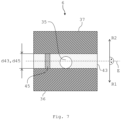
- Die
Fig. 6 und7 zeigen eine weitere Ausführungsform einer Trennplatte 6. Bei dieser Ausführungsform der Trennplatte 6 ist keine wie zuvor erläuterte Nut 38 vorgesehen. Die Trennplatte 6 umfasst einen wie zuvor erläuterten ersten Trennplattenabschnitt 36 sowie einen zweiten Trennplattenabschnitt 37, zwischen denen der Lichtwellenleiter 35 angeordnet ist. Der Lichtwellenleiter 35 kann wiederum die zuvor erläuterte Hülse 44 (in derFig. 7 nicht gezeigt) umfassen. Der erste Trennplattenabschnitt 36 und der zweite Trennplattenabschnitt 37 sind mit Hilfe eines Lots 43 stoffschlüssig miteinander verbunden, wobei der Lichtwellenleiter 35 beziehungsweise die Hülse 44 direkt in das Lot 43 eingebettet ist. - Zwischen dem ersten Trennplattenabschnitt 36 und dem zweiten Trennplattenabschnitt 37 kann eine Stützkonstruktion oder ein Abstandshalter 45 vorgesehen sein, der eine Beschädigung des Lichtwellenleiters 35 bei der Montage der Trennplatte 6 verhindert. Der Abstandshalter 45 weist dabei eine Dicke d45 auf, die größer ist als der Durchmesser d35 (
Fig. 5 ) des Lichtwellenleiters 35. Der Abstandshalter 45 kann eine Stahlleiste sein. Der Abstandshalter 45 ist in das Lot 43 eingebettet. Der Abstandshalter 45 bestimmt auch eine Dicke d43 des Lots 43. Die Dicke d45 kann beispielsweise 170 µm betragen. Das heißt, auch die Dicke d43 des Lots 43 kann dementsprechend 170 µm betragen. - Die
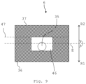
Fig. 8 und9 zeigen eine weitere Ausführungsform einer Trennplatte 6. Bei dieser Ausführungsform der Trennplatte 6 umfasst diese keine zwei voneinander getrennten Trennplattenabschnitte 36, 37, die mit Hilfe eines Lots 43 miteinander verbunden sind. Vielmehr sind zwei einteilig, insbesondere materialeinstückig, miteinander verbundene Trennplattenabschnitte 36, 37 vorgesehen. Das heißt, die Trennplattenabschnitte 36, 37 sind durchgehend aus demselben Material gebildet und somit untrennbar miteinander verbunden. - Bei dieser Ausführungsform der Trennplatte 6 ist der Lichtwellenleiter 35 vollständig von Material der Trennplatte 6 umgeben. Die Trennplatte 6 ist dabei einteilig, insbesondere materialeinstückig, ausgebildet. Hierzu wird die Trennplatte 6 mit Hilfe eines additiven oder generativen Fertigungsverfahrens hergestellt. Beispielsweise kann ein pulverbasiertes generatives Fertigungsverfahren, insbesondere ein 3D-Druckverfahren, verwendet werden. Hierzu wird die Trennplatte 6 aus einem pulverförmigen Werkstoff aufgebaut. Dieser pulverförmige Werkstoff kann beispielsweise mit Hilfe eines Laserstrahls lagenweise aufgeschmolzen werden, um die Trennplatte 6 zu bilden. Beispielsweise kann als generatives Fertigungsverfahren selektives Laserschmelzen (SLM), selektives Lasersintern (SLS) oder dergleichen eingesetzt werden. Dass die Trennplatte 6 mit Hilfe eines generativen Fertigungsverfahrens hergestellt ist, lässt sich mikroskopisch durch einen schichtweisen oder lagenweisen Aufbau der Trennplatte 6 nachweisen.
- In der Trennplatte 6 ist ein Kanal 46 gebildet, in dem der Lichtwellenleiter 35 aufgenommen ist. Der Lichtwellenleiter 35 wiederum kann, wie zuvor erwähnt, in einer Hülse 44 aufgenommen sein. Die Trennplatte 6 kann beispielsweise derart hergestellt werden, dass das Fertigungsverfahren zum Herstellen der Trennplatte 6 so durchgeführt wird, dass zuerst ein in der Orientierung der
Fig. 9 unterer Teil der Trennplatte 6, nämlich der erste Trennplattenabschnitt 36, bis zu einer Trennlinie 47 gefertigt wird. In dem ersten Trennplattenabschnitt 36 ist dann der Kanal 46 für den Lichtwellenleiter 35 vorgesehen. Anschließend wird der Lichtwellenleiter 35 in den Kanal 46 eingelegt und dieser wird mit Hilfe des Fertigungsverfahrens durch Herstellen des zweiten Trennplattenabschnitts 37 geschlossen. Die derart hergestellte integrale Trennplatte 6 kann dann beispielsweise mit einer Lotschicht versehen werden und in einen üblichen Fertigungsprozess zum Herstellen eines wie zuvor erläuterten Plattenwärmetauschers 1 eingebunden werden. - Mit Hilfe der zuvor erwähnten Trennplatte 6 kann eine hochauflösende und exakte Messung der Temperatur und/oder der Dehnung an oder in der Trennplatte 6 selbst erfolgen. Es ist kein zusätzlicher oder nur ein geringfügig zusätzlicher Bauraum erforderlich. Es kann keine unerwünschte Beeinflussung der gemessenen Temperatur durch Umwelteinflüsse geben, da die Trennplatte 6 innerhalb des Plattenwärmetauschers 1 positioniert ist. Es sind sowohl Dehnungs- als auch Temperaturmessung möglich. Hierzu können unterschiedliche Fasertypen für den Lichtwellenleiter 35 gewählt werden. Es können auch mehrere, insbesondere unterschiedliche, Lichtwellenleiter 35 in der Trennplatte 6 vorgesehen sein. Mit Hilfe der Trennplatte 6 kann somit eine Erhöhung der Bauteilsicherheit gegen Versagen beziehungsweise gegen Leckagen nach innen und außen erreicht werden. Die Verfügbarkeit der Trennplatte 6 wird erhöht. In der Trennplatte 6 vorgesehene Kanäle (nicht gezeigt) können auch zur Entnahme von Stoffproben dienen, sofern diese mit der entsprechenden Wärmeübertragungspassage verbunden sind.
- Die
Fig. 10 zeigt ein schematisches Blockdiagramm einer Ausführungsform eines Verfahrens zum Herstellen eines wie zuvor erläuterten Plattenwärmetauschers 1. In einem Schritt S1 wird eine Vielzahl an Lamellen 3, 4 bereitgestellt. Bei dem Bereitstellen der Lamellen 3, 4 können unverformte Rohbleche zu den gewellten oder gestuften Lamellen 3, 4 umgeformt werden. In einem Schritt S2 wird eine Vielzahl an Trennplatten 5 bis 7 bereitgestellt. - In einem Schritt S3 wird zumindest ein Lichtwellenleiter 35 bereitgestellt. In einem weiteren Schritt S4 wird der Lichtwellenleiter 35 in zumindest eine der Trennplatten 5 bis 7, nämlich beispielsweise in die Trennplatte 6, derart eingebettet, dass der Lichtwellenleiter 35 sowohl in der ersten Richtung R1 als auch in der zweiten Richtung R2 betrachtet zweiseitig oder beidseitig von Material der zumindest einen Trennplatte 6 abgedeckt wird. Anschließend können die Lamellen 3, 4 und die Trennplatten 5 bis 7 in einem Schritt S5 abwechselnd angeordnet werden, um den Plattenwärmetauscher 1 zu bilden. Dabei können die die Lamellen 3, 4 und die Trennplatten 5 bis 7 miteinander verlötet oder verschweißt werden.
- Das Einbetten des Lichtwellenleiters 35 kann dabei dadurch erfolgen, dass der Lichtwellenleiter 35 zwischen dem ersten Trennplattenabschnitt 36 und dem zweiten Trennplattenabschnitt 37 angeordnet wird. Die beiden Trennplattenabschnitte 36, 37 können dabei mit Hilfe des Lots 43 stoffschlüssig miteinander verbunden werden. Dabei kann der Lichtwellenleiter 35 entweder in dem Lot 43 eingebettet werden, oder der Lichtwellenleiter wird vor dem Verlöten oder Verschweißen der beiden Trennplattenabschnitte 36, 37 in die an zumindest einem der Trennplattenabschnitte 36, 37 vorgesehene Nut 38 eingelegt. Alternativ kann die Trennplatte 6 auch mit Hilfe eines generativen Fertigungsverfahrens um den Lichtwellenleiter 35 herum aufgebaut werden.
- Obwohl die vorliegende Erfindung anhand von Ausführungsbeispielen beschrieben wurde, ist sie vielfältig modifizierbar.
-
- 1
- Plattenwärmetauscher
- 2
- verfahrenstechnische Anlage
- 3
- Lamelle
- 4
- Lamelle
- 5
- Trennplatte
- 6
- Trennplatte
- 7
- Trennplatte
- 8
- Deckplatte
- 9
- Deckplatte
- 10
- Randleiste
- 11
- Randleiste
- 12
- Stutzen
- 13
- Stutzen
- 14
- Stutzen
- 15
- Stutzen
- 16
- Stutzen
- 17
- Stutzen
- 18
- Stutzen
- 19
- Header
- 20
- Header
- 21
- Header
- 22
- Header
- 23
- Header
- 24
- Header
- 25
- Header
- 26
- Header
- 27
- Header
- 28
- Header
- 29
- Kanal
- 30
- Schenkel
- 31
- Schenkel
- 32
- Schenkel
- 33
- Schenkel
- 34
- Messeinrichtung
- 35
- Lichtwellenleiter
- 36
- Trennplattenabschnitt
- 37
- Trennplattenabschnitt
- 38
- Nut
- 39
- Seitenkante
- 40
- Seitenkante
- 41
- Seitenkante
- 42
- Seitenkante
- 43
- Lot
- 44
- Hülse
- 45
- Abstandshalter
- 46
- Kanal
- 47
- Trennlinie
- d6
- Dicke
- d35
- Durchmesser
- d36
- Dicke
- d37
- Dicke
- d43
- Dicke
- d45
- Dicke
- E
- Ebene
- R1
- Richtung
- R2
- Richtung
- S1
- Schritt
- S2
- Schritt
- S3
- Schritt
- S4
- Schritt
- S5
- Schritt
- t38
- Tiefe
- x
- Breitenrichtung
- y
- Tiefenrichtung
- z
- Dickenrichtung
Claims (7)
- Plattenwärmetauscher (1) für eine verfahrenstechnische Anlage (2), mit einer Vielzahl an Lamellen (3, 4) und einer Vielzahl an Trennplatten (5 - 7), die abwechselnd angeordnet sind, wobei zumindest eine Trennplatte (6) einen Lichtwellenleiter (35) aufweist, der derart in die zumindest eine Trennplatte (6) eingebettet ist, dass der Lichtwellenleiter (35) in einer ersten Richtung (R1) und in einer zweiten Richtung (R2), die jeweils senkrecht zu einer von der zumindest einen Trennplatte (6) aufgespannten Ebene (E) und gegensinnig zueinander orientiert sind, beidseitig von Material der zumindest einen Trennplatte (6) abgedeckt ist, wobei die zumindest eine Trennplatte (6) einen ersten Trennplattenabschnitt (36) und einen zweiten Trennplattenabschnitt (37) aufweist, zwischen denen der Lichtwellenleiter (35) angeordnet ist, wobei der erste Trennplattenabschnitt (36) und der zweite Trennplattenabschnitt (37) mit Hilfe eines Lots (43) stoffschlüssig miteinander verbunden sind, wobei der erste Trennplattenabschnitt (36) und der zweite Trennplattenabschnitt (37) eine Nut (38) aufweist, in der der Lichtwellenleiter (35) angeordnet ist.
- Plattenwärmetauscher nach Anspruch 1, umfassend eine erste Lamelle (3) und eine zweite Lamelle (4), wobei die zumindest eine Trennplatte (6) zwischen der ersten Lamelle (3) und der zweiten Lamelle (4) angeordnet ist, und wobei der Lichtwellenleiter (35) derart in die zumindest eine Trennplatte (6) eingebettet ist, dass der Lichtwellenleiter (35) sowohl in Richtung (R1) der ersten Lamelle (3) als auch in Richtung (R2) der zweiten Lamelle (4) von dem Material der zumindest einen Trennplatte (6) abgedeckt ist.
- Plattenwärmetauscher nach einem der Ansprüche 1 - 2, wobei der Lichtwellenleiter (35) in das Lot (43) eingebettet ist.
- Plattenwärmetauscher nach einem der Ansprüche 1 - 3, wobei der Lichtwellenleiter (35) in einer Hülse (44) aufgenommen ist.
- Verfahrenstechnische Anlage (2) mit einem Plattenwärmetauscher (1) nach einem der Ansprüche 1 - 4.
- Verfahren zum Herstellen eines Plattenwärmetauschers (1) für eine verfahrenstechnische Anlage (2), mit folgenden Schritten:a) Bereitstellen (S1) einer Vielzahl an Lamellen (3, 4),b) Bereitstellen (S2) einer Vielzahl an Trennplatten (5 - 7),c) Bereitstellen (S3) eines Lichtwellenleiters (35),d) Einbetten (S4) des Lichtwellenleiters (35) in zumindest eine Trennplatte (6) derart, dass der Lichtwellenleiter (35) in einer ersten Richtung (R1) und in einer zweiten Richtung (R2), die jeweils senkrecht zu einer von der zumindest einen Trennplatte (6) aufgespannten Ebene (E) und gegensinnig zueinander orientiert sind, beidseitig von Material der zumindest einen Trennplatte (6) abgedeckt wird, wobei der Lichtwellenleiter (35) zwischen einem ersten Trennplattenabschnitt (36) und einem zweiten Trennplattenabschnitt (37) der zumindest einen Trennplatte (6) angeordnet wird, wobei der erste Trennplattenabschnitt (36) und der zweite Trennplattenabschnitt (37) mit Hilfe eines Lots (43) stoffschlüssig miteinander verbunden werden, und wobei der Lichtwellenleiter (35) in einer Nut (38), die der erste Trennplattenabschnitt (36) und der zweite Trennplattenabschnitt (37) aufweist, angeordnet wird,e) abwechselndes Anordnen (S5) der Lamellen (3, 4) und der Trennplatten (5 - 7)
- Verfahren nach Anspruch 6, wobei in dem Schritt d) eine Hülse (44), in der der Lichtwellenleiter (35) aufnehmbar ist, in der Nut (38) angeordnet wird.
Applications Claiming Priority (2)
| Application Number | Priority Date | Filing Date | Title |
|---|---|---|---|
| DE102018003479.9A DE102018003479A1 (de) | 2018-04-27 | 2018-04-27 | Plattenwärmetauscher, verfahrenstechnische Anlage und Verfahren |
| PCT/EP2019/025110 WO2019206455A1 (de) | 2018-04-27 | 2019-04-17 | Plattenwärmetauscher, verfahrenstechnische anlage und verfahren |
Publications (3)
| Publication Number | Publication Date |
|---|---|
| EP3784974A1 EP3784974A1 (de) | 2021-03-03 |
| EP3784974B1 EP3784974B1 (de) | 2022-03-02 |
| EP3784974B2 true EP3784974B2 (de) | 2025-01-15 |
Family
ID=66334345
Family Applications (1)
| Application Number | Title | Priority Date | Filing Date |
|---|---|---|---|
| EP19720366.4A Active EP3784974B2 (de) | 2018-04-27 | 2019-04-17 | Plattenwärmetauscher, verfahrenstechnische anlage und verfahren |
Country Status (8)
| Country | Link |
|---|---|
| US (1) | US20210231382A1 (de) |
| EP (1) | EP3784974B2 (de) |
| JP (1) | JP2021524009A (de) |
| CN (1) | CN112088285A (de) |
| DE (1) | DE102018003479A1 (de) |
| ES (1) | ES2910349T5 (de) |
| HU (1) | HUE058655T2 (de) |
| WO (1) | WO2019206455A1 (de) |
Families Citing this family (4)
| Publication number | Priority date | Publication date | Assignee | Title |
|---|---|---|---|---|
| FR3114142B1 (fr) * | 2020-09-11 | 2022-11-11 | Air Liquide | Dispositif de mesure de températures dans un échangeur de chaleur |
| FR3114143B1 (fr) * | 2020-09-11 | 2022-07-29 | Air Liquide | Dispositif de mesure de températures dans un échangeur de chaleur |
| US11583929B2 (en) * | 2021-02-12 | 2023-02-21 | Raytheon Company | Cold plate design features amenable for additive manufacturing powder removal |
| WO2022179749A1 (de) | 2021-02-25 | 2022-09-01 | Linde Gmbh | Ermittlung von verformungen eines wärmetauscherblocks |
Citations (6)
| Publication number | Priority date | Publication date | Assignee | Title |
|---|---|---|---|---|
| US20120082182A1 (en) † | 2009-06-08 | 2012-04-05 | Sms Siemag Aktiengesellschaft | Integration of an optical waveguide of a sensor into a component |
| JP2014169809A (ja) † | 2013-03-01 | 2014-09-18 | Sumitomo Precision Prod Co Ltd | 積層構造体 |
| US20150241141A1 (en) † | 2012-10-09 | 2015-08-27 | Linde Aktiengesellschaft | Temperature measurement by means of an optical waveguide in a plate heat exchanger |
| US20150369548A1 (en) † | 2012-10-09 | 2015-12-24 | Linde Aktiengesellschaft | Method for controlling a temperature distribution in a heat exchanger |
| DE102016000246A1 (de) † | 2016-01-12 | 2017-07-13 | Linde Aktiengesellschaft | Verfahren zur Bestimmung eines Dehnungslastwechsels eines Plattenwärmeübertragers |
| US20180045471A1 (en) † | 2015-03-05 | 2018-02-15 | Linde Aktiengesellschaft | 3d-printed heating surface element for a plate heat exchanger |
Family Cites Families (21)
| Publication number | Priority date | Publication date | Assignee | Title |
|---|---|---|---|---|
| JP3211540B2 (ja) * | 1994-01-20 | 2001-09-25 | 住友電気工業株式会社 | 光送受信モジュール |
| JPH08153929A (ja) * | 1994-11-28 | 1996-06-11 | Mitsubishi Electric Corp | 半導体レーザ装置とその製造方法 |
| JPH09119872A (ja) * | 1995-10-26 | 1997-05-06 | Toshiba Corp | 温度測定センサ |
| JPH10282357A (ja) * | 1997-02-07 | 1998-10-23 | Ngk Insulators Ltd | 光伝送部材保持装置 |
| FR2819048B1 (fr) * | 2000-12-28 | 2005-08-19 | Air Liquide | Ailette ondulee pour echangeur de chaleur a plaques brasees et echangeur de chaleur correspondant |
| JP2008140800A (ja) * | 2006-11-30 | 2008-06-19 | Meidensha Corp | プリント基板のはんだ部の歪または温度の測定方法及びプリント基板 |
| DE102008033302A1 (de) * | 2008-07-15 | 2010-01-21 | Linde Aktiengesellschaft | Ermüdungsfester Plattenwärmetauscher |
| DE102010008481A1 (de) * | 2009-09-30 | 2011-03-31 | Sms Siemag Ag | Metallurgisches Gefäß |
| DE102010025562A1 (de) * | 2010-02-18 | 2011-08-18 | SMS Siemag AG, 40237 | Injektorkühlblock zur Halterung mindestens eines Injektors |
| CN102798305A (zh) * | 2011-05-24 | 2012-11-28 | 四平市巨元瀚洋板式换热器有限公司 | 半焊式板式换热器 |
| EP3006875A1 (de) * | 2014-10-09 | 2016-04-13 | Linde Aktiengesellschaft | Verfahren zur Regelung eines gekoppelten Wärmetauscher-Systems und Wärmetauscher-System |
| DE102014018825A1 (de) * | 2014-12-19 | 2016-06-23 | Man Diesel & Turbo Se | Faseroptische Temperaturmessung |
| US11480398B2 (en) * | 2015-05-22 | 2022-10-25 | The Johns Hopkins University | Combining complex flow manifold with three dimensional woven lattices as a thermal management unit |
| DE102015211559A1 (de) * | 2015-06-23 | 2016-12-29 | Airbus Operations Gmbh | Metallbauteil mit integrierten Glasfasern für ein Luft- oder Raumfahrzeug und 3D-Druckverfahren zur Herstellung eines Metallbauteils mit integrierten Glasfasern |
| US10646969B2 (en) * | 2015-12-02 | 2020-05-12 | Hamilton Sunstrand Corporation | Cross flow ceramic heat exchanger and method for manufacturing |
| US11346608B2 (en) * | 2016-01-29 | 2022-05-31 | Deere & Company | Heat exchanger with improved plugging resistance |
| FR3069918B1 (fr) * | 2017-08-04 | 2020-01-17 | L'air Liquide, Societe Anonyme Pour L'etude Et L'exploitation Des Procedes Georges Claude | Echangeur de chaleur comprenant un element de distribution a canaux multiples |
| WO2019100170A1 (en) * | 2017-11-27 | 2019-05-31 | Dana Canada Corporation | Enhanced heat transfer surface |
| US11365942B2 (en) * | 2018-03-16 | 2022-06-21 | Hamilton Sundstrand Corporation | Integral heat exchanger mounts |
| US20190293364A1 (en) * | 2018-03-22 | 2019-09-26 | Johnson Controls Technology Company | Varied geometry heat exchanger systems and methods |
| US10962306B2 (en) * | 2018-03-23 | 2021-03-30 | Raytheon Technologies Corporation | Shaped leading edge of cast plate fin heat exchanger |
-
2018
- 2018-04-27 DE DE102018003479.9A patent/DE102018003479A1/de not_active Withdrawn
-
2019
- 2019-04-17 JP JP2020560214A patent/JP2021524009A/ja active Pending
- 2019-04-17 WO PCT/EP2019/025110 patent/WO2019206455A1/de not_active Ceased
- 2019-04-17 CN CN201980028287.XA patent/CN112088285A/zh active Pending
- 2019-04-17 US US17/051,122 patent/US20210231382A1/en not_active Abandoned
- 2019-04-17 EP EP19720366.4A patent/EP3784974B2/de active Active
- 2019-04-17 HU HUE19720366A patent/HUE058655T2/hu unknown
- 2019-04-17 ES ES19720366T patent/ES2910349T5/es active Active
Patent Citations (6)
| Publication number | Priority date | Publication date | Assignee | Title |
|---|---|---|---|---|
| US20120082182A1 (en) † | 2009-06-08 | 2012-04-05 | Sms Siemag Aktiengesellschaft | Integration of an optical waveguide of a sensor into a component |
| US20150241141A1 (en) † | 2012-10-09 | 2015-08-27 | Linde Aktiengesellschaft | Temperature measurement by means of an optical waveguide in a plate heat exchanger |
| US20150369548A1 (en) † | 2012-10-09 | 2015-12-24 | Linde Aktiengesellschaft | Method for controlling a temperature distribution in a heat exchanger |
| JP2014169809A (ja) † | 2013-03-01 | 2014-09-18 | Sumitomo Precision Prod Co Ltd | 積層構造体 |
| US20180045471A1 (en) † | 2015-03-05 | 2018-02-15 | Linde Aktiengesellschaft | 3d-printed heating surface element for a plate heat exchanger |
| DE102016000246A1 (de) † | 2016-01-12 | 2017-07-13 | Linde Aktiengesellschaft | Verfahren zur Bestimmung eines Dehnungslastwechsels eines Plattenwärmeübertragers |
Non-Patent Citations (6)
| Title |
|---|
| "Additive Manufacturing Technologies 3D Printing, Rapid Prototyping, and Direct Digital Manufacturing, second edition", 2010, SPRINGER, article I. GUBSON ET AL.: "Additive Manufacturing Technologies 3D Printing, Rapid Prototyping, and Direct Digital Manufacturing, second edition", pages: 1 - 510 † |
| "Handbook of Modern Sensors: Physics, Designs, and Applications", 2010, SPRINGER, article FRADEN JACOB: "Handbook of Modern Sensors: Physics, Designs, and Applications, fourth edition", pages: 353 - 355 † |
| "Optical Waveguide Sensing and Imaging", 2008, SPRINGER, article BOCK W., ET AL.: "Chapter 7", pages: 114 - 115 † |
| ANONYMOUS: "THE STANDARDS OF THE BRAZED ALUMINIUM PLATE-FIN HEAT EXCHANGER MANUFACTURERS' ASSOCIATION", ALPEMA, 2000, pages 1 - 78 † |
| Traduction machine de D5 † |
| Traduction machine de DI † |
Also Published As
| Publication number | Publication date |
|---|---|
| EP3784974A1 (de) | 2021-03-03 |
| WO2019206455A8 (de) | 2020-07-23 |
| JP2021524009A (ja) | 2021-09-09 |
| WO2019206455A1 (de) | 2019-10-31 |
| DE102018003479A1 (de) | 2019-10-31 |
| ES2910349T5 (en) | 2025-04-15 |
| US20210231382A1 (en) | 2021-07-29 |
| HUE058655T2 (hu) | 2022-09-28 |
| CN112088285A (zh) | 2020-12-15 |
| EP3784974B1 (de) | 2022-03-02 |
| ES2910349T3 (es) | 2022-05-12 |
Similar Documents
| Publication | Publication Date | Title |
|---|---|---|
| EP3784974B2 (de) | Plattenwärmetauscher, verfahrenstechnische anlage und verfahren | |
| DE10012291C1 (de) | Verfahren zur faseroptischen Temperaturmessung und faseroptischer Temperatursensor | |
| EP3233261B1 (de) | Faseroptische temperaturmessung in einer katalysatorschüttung | |
| EP2310155B1 (de) | Temperaturmessung in einer kokille durch ein faseroptisches messverfahren | |
| EP2293891B1 (de) | Kokille zum giessen von metall | |
| DE102009049479B4 (de) | Einbindung eines Lichtwellenleiters eines Messsensors in ein Bauteil | |
| EP3617696B1 (de) | Messeinrichtung für die wärmeleitfähigkeit eines fluids | |
| EP2906919B1 (de) | Temperaturmessung mittels eines lichtwellenleiters in einem plattenwärmetauscher | |
| EP3680599B1 (de) | Verfahren zum herstellen eines plattenwärmetauschers sowie plattenwärmetauscher mit thermoelementen oder messwiderständen | |
| WO2003027654A2 (de) | Sensorbaustein mit einem sensorelement, das von einem heizelement umgeben ist | |
| DE4416616C2 (de) | Gehäuse | |
| DE2809181B2 (de) | Sicherheits-Zentrierkorb | |
| DE2549359A1 (de) | Kuehlturm | |
| WO2011023377A2 (de) | Überwachung von walzenlagern | |
| DE19606972A1 (de) | Kühlkörper zum Kühlen von Leistungsbauelementen | |
| DE1527970B2 (de) | Vorrichtung zur kontinuierlichen Herstellung von Abstandhaltern für Wärmetauscher | |
| DE69702543T2 (de) | Wicklungsanordnung für Transformator | |
| DE19600393A1 (de) | Leiterrahmen und Halbleitervorrichtung | |
| EP3640604A1 (de) | Magnetisch-induktives durchflussmessgerät, magnetkreisvorrichtung und verfahren zur herstellung einer magnetkreisvorrichtung | |
| EP3825636B1 (de) | Wärmetauscher und verfahren zu dessen herstellung beziehungsweise entwurf | |
| DE102009060548B4 (de) | Kokille für eine Stranggießanlage und Verwendung einer solchen Kokille | |
| DE202013103733U1 (de) | Schneller Stufentemperaturfühler | |
| EP3546906B1 (de) | Temperatursensoranordnung, temperatursensorbauteil für eine metallurgische anlage und verfahren zum herstellen eines solchen | |
| DE102020204501A1 (de) | Wärmeflusssensor, Wärmeflusserfassungsvorrichtung sowie Temperaturüberwachungsvorrichtung | |
| DE1573374C3 (de) | Folienwärmestrommesser für die Messung von Lokalwerten der Wärmeübergangszahlen und Verfahren zu dessen Herstellung |
Legal Events
| Date | Code | Title | Description |
|---|---|---|---|
| STAA | Information on the status of an ep patent application or granted ep patent |
Free format text: STATUS: UNKNOWN |
|
| STAA | Information on the status of an ep patent application or granted ep patent |
Free format text: STATUS: THE INTERNATIONAL PUBLICATION HAS BEEN MADE |
|
| PUAI | Public reference made under article 153(3) epc to a published international application that has entered the european phase |
Free format text: ORIGINAL CODE: 0009012 |
|
| STAA | Information on the status of an ep patent application or granted ep patent |
Free format text: STATUS: REQUEST FOR EXAMINATION WAS MADE |
|
| 17P | Request for examination filed |
Effective date: 20201022 |
|
| AK | Designated contracting states |
Kind code of ref document: A1 Designated state(s): AL AT BE BG CH CY CZ DE DK EE ES FI FR GB GR HR HU IE IS IT LI LT LU LV MC MK MT NL NO PL PT RO RS SE SI SK SM TR |
|
| AX | Request for extension of the european patent |
Extension state: BA ME |
|
| RIN1 | Information on inventor provided before grant (corrected) |
Inventor name: GEWALD, STEFAN Inventor name: BLANK, JANINE Inventor name: BRAUN, KONRAD Inventor name: KERBER, CHRISTIANE Inventor name: FLUEGGEN, RAINER Inventor name: WOITALKA, ALEXANDER Inventor name: LEHMACHER, AXEL Inventor name: STEINBAUER, MANFRED Inventor name: BAUMGARTNER, CLEMENS Inventor name: HOFFMANN, RAINER |
|
| DAV | Request for validation of the european patent (deleted) | ||
| DAX | Request for extension of the european patent (deleted) | ||
| GRAP | Despatch of communication of intention to grant a patent |
Free format text: ORIGINAL CODE: EPIDOSNIGR1 |
|
| STAA | Information on the status of an ep patent application or granted ep patent |
Free format text: STATUS: GRANT OF PATENT IS INTENDED |
|
| INTG | Intention to grant announced |
Effective date: 20211019 |
|
| GRAS | Grant fee paid |
Free format text: ORIGINAL CODE: EPIDOSNIGR3 |
|
| GRAA | (expected) grant |
Free format text: ORIGINAL CODE: 0009210 |
|
| STAA | Information on the status of an ep patent application or granted ep patent |
Free format text: STATUS: THE PATENT HAS BEEN GRANTED |
|
| AK | Designated contracting states |
Kind code of ref document: B1 Designated state(s): AL AT BE BG CH CY CZ DE DK EE ES FI FR GB GR HR HU IE IS IT LI LT LU LV MC MK MT NL NO PL PT RO RS SE SI SK SM TR |
|
| REG | Reference to a national code |
Ref country code: GB Ref legal event code: FG4D Free format text: NOT ENGLISH |
|
| REG | Reference to a national code |
Ref country code: CH Ref legal event code: EP Ref country code: AT Ref legal event code: REF Ref document number: 1472569 Country of ref document: AT Kind code of ref document: T Effective date: 20220315 |
|
| REG | Reference to a national code |
Ref country code: DE Ref legal event code: R096 Ref document number: 502019003584 Country of ref document: DE |
|
| REG | Reference to a national code |
Ref country code: IE Ref legal event code: FG4D Free format text: LANGUAGE OF EP DOCUMENT: GERMAN |
|
| REG | Reference to a national code |
Ref country code: SE Ref legal event code: TRGR |
|
| REG | Reference to a national code |
Ref country code: NL Ref legal event code: FP |
|
| REG | Reference to a national code |
Ref country code: ES Ref legal event code: FG2A Ref document number: 2910349 Country of ref document: ES Kind code of ref document: T3 Effective date: 20220512 |
|
| REG | Reference to a national code |
Ref country code: NO Ref legal event code: T2 Effective date: 20220302 |
|
| REG | Reference to a national code |
Ref country code: LT Ref legal event code: MG9D |
|
| PG25 | Lapsed in a contracting state [announced via postgrant information from national office to epo] |
Ref country code: RS Free format text: LAPSE BECAUSE OF FAILURE TO SUBMIT A TRANSLATION OF THE DESCRIPTION OR TO PAY THE FEE WITHIN THE PRESCRIBED TIME-LIMIT Effective date: 20220302 Ref country code: LT Free format text: LAPSE BECAUSE OF FAILURE TO SUBMIT A TRANSLATION OF THE DESCRIPTION OR TO PAY THE FEE WITHIN THE PRESCRIBED TIME-LIMIT Effective date: 20220302 Ref country code: HR Free format text: LAPSE BECAUSE OF FAILURE TO SUBMIT A TRANSLATION OF THE DESCRIPTION OR TO PAY THE FEE WITHIN THE PRESCRIBED TIME-LIMIT Effective date: 20220302 Ref country code: BG Free format text: LAPSE BECAUSE OF FAILURE TO SUBMIT A TRANSLATION OF THE DESCRIPTION OR TO PAY THE FEE WITHIN THE PRESCRIBED TIME-LIMIT Effective date: 20220602 |
|
| PG25 | Lapsed in a contracting state [announced via postgrant information from national office to epo] |
Ref country code: PL Free format text: LAPSE BECAUSE OF FAILURE TO SUBMIT A TRANSLATION OF THE DESCRIPTION OR TO PAY THE FEE WITHIN THE PRESCRIBED TIME-LIMIT Effective date: 20220302 Ref country code: LV Free format text: LAPSE BECAUSE OF FAILURE TO SUBMIT A TRANSLATION OF THE DESCRIPTION OR TO PAY THE FEE WITHIN THE PRESCRIBED TIME-LIMIT Effective date: 20220302 Ref country code: GR Free format text: LAPSE BECAUSE OF FAILURE TO SUBMIT A TRANSLATION OF THE DESCRIPTION OR TO PAY THE FEE WITHIN THE PRESCRIBED TIME-LIMIT Effective date: 20220603 Ref country code: FI Free format text: LAPSE BECAUSE OF FAILURE TO SUBMIT A TRANSLATION OF THE DESCRIPTION OR TO PAY THE FEE WITHIN THE PRESCRIBED TIME-LIMIT Effective date: 20220302 |
|
| REG | Reference to a national code |
Ref country code: HU Ref legal event code: AG4A Ref document number: E058655 Country of ref document: HU |
|
| PG25 | Lapsed in a contracting state [announced via postgrant information from national office to epo] |
Ref country code: SM Free format text: LAPSE BECAUSE OF FAILURE TO SUBMIT A TRANSLATION OF THE DESCRIPTION OR TO PAY THE FEE WITHIN THE PRESCRIBED TIME-LIMIT Effective date: 20220302 Ref country code: SK Free format text: LAPSE BECAUSE OF FAILURE TO SUBMIT A TRANSLATION OF THE DESCRIPTION OR TO PAY THE FEE WITHIN THE PRESCRIBED TIME-LIMIT Effective date: 20220302 Ref country code: RO Free format text: LAPSE BECAUSE OF FAILURE TO SUBMIT A TRANSLATION OF THE DESCRIPTION OR TO PAY THE FEE WITHIN THE PRESCRIBED TIME-LIMIT Effective date: 20220302 Ref country code: PT Free format text: LAPSE BECAUSE OF FAILURE TO SUBMIT A TRANSLATION OF THE DESCRIPTION OR TO PAY THE FEE WITHIN THE PRESCRIBED TIME-LIMIT Effective date: 20220704 Ref country code: EE Free format text: LAPSE BECAUSE OF FAILURE TO SUBMIT A TRANSLATION OF THE DESCRIPTION OR TO PAY THE FEE WITHIN THE PRESCRIBED TIME-LIMIT Effective date: 20220302 Ref country code: CZ Free format text: LAPSE BECAUSE OF FAILURE TO SUBMIT A TRANSLATION OF THE DESCRIPTION OR TO PAY THE FEE WITHIN THE PRESCRIBED TIME-LIMIT Effective date: 20220302 |
|
| PG25 | Lapsed in a contracting state [announced via postgrant information from national office to epo] |
Ref country code: IS Free format text: LAPSE BECAUSE OF FAILURE TO SUBMIT A TRANSLATION OF THE DESCRIPTION OR TO PAY THE FEE WITHIN THE PRESCRIBED TIME-LIMIT Effective date: 20220702 Ref country code: AL Free format text: LAPSE BECAUSE OF FAILURE TO SUBMIT A TRANSLATION OF THE DESCRIPTION OR TO PAY THE FEE WITHIN THE PRESCRIBED TIME-LIMIT Effective date: 20220302 |
|
| REG | Reference to a national code |
Ref country code: CH Ref legal event code: PL |
|
| REG | Reference to a national code |
Ref country code: DE Ref legal event code: R026 Ref document number: 502019003584 Country of ref document: DE |
|
| PLBI | Opposition filed |
Free format text: ORIGINAL CODE: 0009260 |
|
| PLAB | Opposition data, opponent's data or that of the opponent's representative modified |
Free format text: ORIGINAL CODE: 0009299OPPO |
|
| PLAX | Notice of opposition and request to file observation + time limit sent |
Free format text: ORIGINAL CODE: EPIDOSNOBS2 |
|
| 26 | Opposition filed |
Opponent name: L'AIR LIQUIDE, SOCIETE ANONYME POUR L'ETUDE ET L'EXPLOITATION DES PROCEDES GEORGES CLAUDE Effective date: 20221201 |
|
| R26 | Opposition filed (corrected) |
Opponent name: L'AIR LIQUIDE, SOCIETE ANONYME POUR L'ETUDE ET L'EXPLOITATION DES PROCEDES GEORGES CLAUDE Effective date: 20221201 |
|
| PG25 | Lapsed in a contracting state [announced via postgrant information from national office to epo] |
Ref country code: MC Free format text: LAPSE BECAUSE OF FAILURE TO SUBMIT A TRANSLATION OF THE DESCRIPTION OR TO PAY THE FEE WITHIN THE PRESCRIBED TIME-LIMIT Effective date: 20220302 Ref country code: LU Free format text: LAPSE BECAUSE OF NON-PAYMENT OF DUE FEES Effective date: 20220417 Ref country code: LI Free format text: LAPSE BECAUSE OF NON-PAYMENT OF DUE FEES Effective date: 20220430 Ref country code: DK Free format text: LAPSE BECAUSE OF FAILURE TO SUBMIT A TRANSLATION OF THE DESCRIPTION OR TO PAY THE FEE WITHIN THE PRESCRIBED TIME-LIMIT Effective date: 20220302 Ref country code: CH Free format text: LAPSE BECAUSE OF NON-PAYMENT OF DUE FEES Effective date: 20220430 |
|
| PG25 | Lapsed in a contracting state [announced via postgrant information from national office to epo] |
Ref country code: SI Free format text: LAPSE BECAUSE OF FAILURE TO SUBMIT A TRANSLATION OF THE DESCRIPTION OR TO PAY THE FEE WITHIN THE PRESCRIBED TIME-LIMIT Effective date: 20220302 |
|
| PLBB | Reply of patent proprietor to notice(s) of opposition received |
Free format text: ORIGINAL CODE: EPIDOSNOBS3 |
|
| PG25 | Lapsed in a contracting state [announced via postgrant information from national office to epo] |
Ref country code: IE Free format text: LAPSE BECAUSE OF NON-PAYMENT OF DUE FEES Effective date: 20220417 |
|
| P01 | Opt-out of the competence of the unified patent court (upc) registered |
Effective date: 20230527 |
|
| PG25 | Lapsed in a contracting state [announced via postgrant information from national office to epo] |
Ref country code: MK Free format text: LAPSE BECAUSE OF FAILURE TO SUBMIT A TRANSLATION OF THE DESCRIPTION OR TO PAY THE FEE WITHIN THE PRESCRIBED TIME-LIMIT Effective date: 20220302 Ref country code: CY Free format text: LAPSE BECAUSE OF FAILURE TO SUBMIT A TRANSLATION OF THE DESCRIPTION OR TO PAY THE FEE WITHIN THE PRESCRIBED TIME-LIMIT Effective date: 20220302 |
|
| PG25 | Lapsed in a contracting state [announced via postgrant information from national office to epo] |
Ref country code: MT Free format text: LAPSE BECAUSE OF FAILURE TO SUBMIT A TRANSLATION OF THE DESCRIPTION OR TO PAY THE FEE WITHIN THE PRESCRIBED TIME-LIMIT Effective date: 20220302 |
|
| PUAH | Patent maintained in amended form |
Free format text: ORIGINAL CODE: 0009272 |
|
| STAA | Information on the status of an ep patent application or granted ep patent |
Free format text: STATUS: PATENT MAINTAINED AS AMENDED |
|
| 27A | Patent maintained in amended form |
Effective date: 20250115 |
|
| AK | Designated contracting states |
Kind code of ref document: B2 Designated state(s): AL AT BE BG CH CY CZ DE DK EE ES FI FR GB GR HR HU IE IS IT LI LT LU LV MC MK MT NL NO PL PT RO RS SE SI SK SM TR |
|
| REG | Reference to a national code |
Ref country code: DE Ref legal event code: R102 Ref document number: 502019003584 Country of ref document: DE |
|
| REG | Reference to a national code |
Ref country code: NL Ref legal event code: FP |
|
| REG | Reference to a national code |
Ref country code: SE Ref legal event code: RPEO |
|
| REG | Reference to a national code |
Ref country code: ES Ref legal event code: DC2A Ref document number: 2910349 Country of ref document: ES Kind code of ref document: T5 Effective date: 20250415 |
|
| PGFP | Annual fee paid to national office [announced via postgrant information from national office to epo] |
Ref country code: NL Payment date: 20250422 Year of fee payment: 7 |
|
| REG | Reference to a national code |
Ref country code: AT Ref legal event code: MM01 Ref document number: 1472569 Country of ref document: AT Kind code of ref document: T Effective date: 20240417 |
|
| PGFP | Annual fee paid to national office [announced via postgrant information from national office to epo] |
Ref country code: DE Payment date: 20250417 Year of fee payment: 7 |
|
| PGFP | Annual fee paid to national office [announced via postgrant information from national office to epo] |
Ref country code: ES Payment date: 20250519 Year of fee payment: 7 Ref country code: GB Payment date: 20250423 Year of fee payment: 7 |
|
| PGFP | Annual fee paid to national office [announced via postgrant information from national office to epo] |
Ref country code: HU Payment date: 20250411 Year of fee payment: 7 Ref country code: NO Payment date: 20250422 Year of fee payment: 7 |
|
| PGFP | Annual fee paid to national office [announced via postgrant information from national office to epo] |
Ref country code: BE Payment date: 20250422 Year of fee payment: 7 Ref country code: IT Payment date: 20250430 Year of fee payment: 7 |
|
| PGFP | Annual fee paid to national office [announced via postgrant information from national office to epo] |
Ref country code: FR Payment date: 20250428 Year of fee payment: 7 |
|
| PG25 | Lapsed in a contracting state [announced via postgrant information from national office to epo] |
Ref country code: AT Free format text: LAPSE BECAUSE OF NON-PAYMENT OF DUE FEES Effective date: 20240417 |
|
| PGFP | Annual fee paid to national office [announced via postgrant information from national office to epo] |
Ref country code: TR Payment date: 20250409 Year of fee payment: 7 |
|
| PGFP | Annual fee paid to national office [announced via postgrant information from national office to epo] |
Ref country code: SE Payment date: 20250423 Year of fee payment: 7 |