EP3784510B1 - Verfahren zum herstellen einer antriebskabelhalterung für ein fahrzeugdach und bauteil für ein fahrzeugdach - Google Patents
Verfahren zum herstellen einer antriebskabelhalterung für ein fahrzeugdach und bauteil für ein fahrzeugdach Download PDFInfo
- Publication number
- EP3784510B1 EP3784510B1 EP19720506.5A EP19720506A EP3784510B1 EP 3784510 B1 EP3784510 B1 EP 3784510B1 EP 19720506 A EP19720506 A EP 19720506A EP 3784510 B1 EP3784510 B1 EP 3784510B1
- Authority
- EP
- European Patent Office
- Prior art keywords
- drive
- component
- cable holder
- plastic
- holder
- Prior art date
- Legal status (The legal status is an assumption and is not a legal conclusion. Google has not performed a legal analysis and makes no representation as to the accuracy of the status listed.)
- Active
Links
Images

Classifications
-
- B—PERFORMING OPERATIONS; TRANSPORTING
- B60—VEHICLES IN GENERAL
- B60J—WINDOWS, WINDSCREENS, NON-FIXED ROOFS, DOORS, OR SIMILAR DEVICES FOR VEHICLES; REMOVABLE EXTERNAL PROTECTIVE COVERINGS SPECIALLY ADAPTED FOR VEHICLES
- B60J7/00—Non-fixed roofs; Roofs with movable panels, e.g. rotary sunroofs
- B60J7/02—Non-fixed roofs; Roofs with movable panels, e.g. rotary sunroofs of sliding type, e.g. comprising guide shoes
- B60J7/04—Non-fixed roofs; Roofs with movable panels, e.g. rotary sunroofs of sliding type, e.g. comprising guide shoes with rigid plate-like element or elements, e.g. open roofs with harmonica-type folding rigid panels
- B60J7/057—Driving or actuating arrangements e.g. manually operated levers or knobs
- B60J7/0573—Driving or actuating arrangements e.g. manually operated levers or knobs power driven arrangements, e.g. electrical
-
- B—PERFORMING OPERATIONS; TRANSPORTING
- B29—WORKING OF PLASTICS; WORKING OF SUBSTANCES IN A PLASTIC STATE IN GENERAL
- B29C—SHAPING OR JOINING OF PLASTICS; SHAPING OF MATERIAL IN A PLASTIC STATE, NOT OTHERWISE PROVIDED FOR; AFTER-TREATMENT OF THE SHAPED PRODUCTS, e.g. REPAIRING
- B29C44/00—Shaping by internal pressure generated in the material, e.g. swelling or foaming ; Producing porous or cellular expanded plastics articles
- B29C44/02—Shaping by internal pressure generated in the material, e.g. swelling or foaming ; Producing porous or cellular expanded plastics articles for articles of definite length, i.e. discrete articles
- B29C44/12—Incorporating or moulding on preformed parts, e.g. inserts or reinforcements
- B29C44/1266—Incorporating or moulding on preformed parts, e.g. inserts or reinforcements the preformed part being completely encapsulated, e.g. for packaging purposes or as reinforcement
-
- B—PERFORMING OPERATIONS; TRANSPORTING
- B62—LAND VEHICLES FOR TRAVELLING OTHERWISE THAN ON RAILS
- B62D—MOTOR VEHICLES; TRAILERS
- B62D65/00—Designing, manufacturing, e.g. assembling, facilitating disassembly, or structurally modifying motor vehicles or trailers, not otherwise provided for
- B62D65/02—Joining sub-units or components to, or positioning sub-units or components with respect to, body shell or other sub-units or components
- B62D65/14—Joining sub-units or components to, or positioning sub-units or components with respect to, body shell or other sub-units or components the sub-units or components being passenger compartment fittings, e.g. seats, linings, trim, instrument panels
-
- H—ELECTRICITY
- H02—GENERATION; CONVERSION OR DISTRIBUTION OF ELECTRIC POWER
- H02G—INSTALLATION OF ELECTRIC CABLES OR LINES, OR OF COMBINED OPTICAL AND ELECTRIC CABLES OR LINES
- H02G3/00—Installations of electric cables or lines or protective tubing therefor in or on buildings, equivalent structures or vehicles
- H02G3/02—Details
- H02G3/04—Protective tubing or conduits, e.g. cable ladders or cable troughs
- H02G3/0462—Tubings, i.e. having a closed section
- H02G3/0487—Tubings, i.e. having a closed section with a non-circular cross-section
-
- B—PERFORMING OPERATIONS; TRANSPORTING
- B29—WORKING OF PLASTICS; WORKING OF SUBSTANCES IN A PLASTIC STATE IN GENERAL
- B29C—SHAPING OR JOINING OF PLASTICS; SHAPING OF MATERIAL IN A PLASTIC STATE, NOT OTHERWISE PROVIDED FOR; AFTER-TREATMENT OF THE SHAPED PRODUCTS, e.g. REPAIRING
- B29C67/00—Shaping techniques not covered by groups B29C39/00 - B29C65/00, B29C70/00 or B29C73/00
- B29C67/24—Shaping techniques not covered by groups B29C39/00 - B29C65/00, B29C70/00 or B29C73/00 characterised by the choice of material
- B29C67/246—Moulding high reactive monomers or prepolymers, e.g. by reaction injection moulding [RIM], liquid injection moulding [LIM]
-
- B—PERFORMING OPERATIONS; TRANSPORTING
- B29—WORKING OF PLASTICS; WORKING OF SUBSTANCES IN A PLASTIC STATE IN GENERAL
- B29K—INDEXING SCHEME ASSOCIATED WITH SUBCLASSES B29B, B29C OR B29D, RELATING TO MOULDING MATERIALS OR TO MATERIALS FOR MOULDS, REINFORCEMENTS, FILLERS OR PREFORMED PARTS, e.g. INSERTS
- B29K2075/00—Use of PU, i.e. polyureas or polyurethanes or derivatives thereof, as moulding material
-
- B—PERFORMING OPERATIONS; TRANSPORTING
- B29—WORKING OF PLASTICS; WORKING OF SUBSTANCES IN A PLASTIC STATE IN GENERAL
- B29K—INDEXING SCHEME ASSOCIATED WITH SUBCLASSES B29B, B29C OR B29D, RELATING TO MOULDING MATERIALS OR TO MATERIALS FOR MOULDS, REINFORCEMENTS, FILLERS OR PREFORMED PARTS, e.g. INSERTS
- B29K2105/00—Condition, form or state of moulded material or of the material to be shaped
- B29K2105/04—Condition, form or state of moulded material or of the material to be shaped cellular or porous
-
- B—PERFORMING OPERATIONS; TRANSPORTING
- B29—WORKING OF PLASTICS; WORKING OF SUBSTANCES IN A PLASTIC STATE IN GENERAL
- B29L—INDEXING SCHEME ASSOCIATED WITH SUBCLASS B29C, RELATING TO PARTICULAR ARTICLES
- B29L2031/00—Other particular articles
- B29L2031/30—Vehicles, e.g. ships or aircraft, or body parts thereof
- B29L2031/3005—Body finishings
- B29L2031/3011—Roof linings
-
- B—PERFORMING OPERATIONS; TRANSPORTING
- B29—WORKING OF PLASTICS; WORKING OF SUBSTANCES IN A PLASTIC STATE IN GENERAL
- B29L—INDEXING SCHEME ASSOCIATED WITH SUBCLASS B29C, RELATING TO PARTICULAR ARTICLES
- B29L2031/00—Other particular articles
- B29L2031/34—Electrical apparatus, e.g. sparking plugs or parts thereof
- B29L2031/3462—Cables
Definitions
- a method of making a power cable holder for a vehicle roof is provided.
- a component for a vehicle roof is specified that has a drive cable holder.
- a motor vehicle can have a roof opening that can be closed and at least partially opened by means of a movable cover.
- the movement of the lid is driven by a drive which is coupled to the lid by means of a drive cable.
- a roller blind in a motor vehicle that can be moved by means of a drive and a drive cable.
- the drive cable is guided, for example, in a guide tube as in the DE 101 44 742 A1 described.
- the DE 201 22 831 U1 relates to a drive cable that is guided in a cable tube that is foamed into a support frame.
- US 2004/169400 A1 describes a vehicle roof module that is firmly connected to a body frame of the vehicle.
- DE 10 2015 119 405 A1 relates to a sunroof module with a cross part on which a drive device is arranged.
- DE 100 39 522 A1 relates to a sun blind that is held on the inner shell by means of elements foamed into a frame-like inner shell.
- the invention relates to a method with the features according to claim 1 and a component with the features according to claim 8.
- a method for producing a drive cable holder for a vehicle roof includes providing a component for the vehicle roof.
- the component is positioned in a mold.
- a guide tube for a drive cable is provided.
- the guide tube is positioned in the mold.
- the guide tube and the component are positioned relative to one another and relative to the mold, so that predetermined positions are achieved.
- a plastic is introduced into the mold.
- the plastic completely surrounds the guide tube radially in the mold, at least in sections.
- the plastic comes into contact with a surface of the component in the mold. This forms the drive cable holder that is attached to the component.
- the drive cable holder is formed after the plastic has hardened.
- the method enables the guide tube to be directly connected to the component.
- Fasteners such as rivets or screws or adhesive connections can be dispensed with.
- just a few procedural steps are sufficient.
- process steps and thus costs are saved.
- no tools are required that are traditionally required to insert the tubes into the plastic part.
- the drive cable holder is also more space-saving than conventional plastic parts.
- the drive cable holder requires a comparatively small amount of installation space. This means that, for example, the visibility can be increased on a transparent vehicle roof.
- a holding element for holding the guide tube in the mold is provided.
- the holding element is removed after the plastic has been inserted. This creates free access to the guide tube at a position of the drive cable holder that corresponds to the holding element.
- the holding of the guide tube in the mold is only required in short sections in which the holding elements are arranged.
- the guide tube in the mold is freely accessible between the holding elements. Consequently, in the areas outside the holding elements, the guide tube can be completely surrounded radially with the plastic. At the holding elements, the guide tube is not completely surrounded by the plastic, but only partially. This leaves free access, but does not have any negative influence on the stability of the drive cable holder.
- a holder for a drive is provided.
- the holder is positioned in the mold before the plastic is introduced.
- the plastic is placed into the mold so that the plastic holds the bracket when the drive bracket is formed.
- the holder is positioned in particular relative to the component and the guide tube at a predetermined position at which the drive is to be mounted in the finished drive cable holder.
- the drive is, for example, an electric drive and has, for example, an electric motor.
- the electric motor is in the operational state, in particular in contact with a drive cable that is guided in the guide tube, so that the drive can move the guide cable along the guide tube.
- a cohesive connection is formed between the plastic and the component for fastening the drive cable holder to the component.
- the plastic is introduced into the mold in such a way that the cohesive connection is formed. It is therefore possible to dispense with further mechanical connections for holding the drive cable holder on the component.
- a plurality of guide tubes are provided, each of which is designed to guide a drive cable.
- the majority of the guide tubes are at least partially positioned in different planes in the mold.
- the planes are spaced apart from one another parallel to a main direction of extension of the guide tubes.
- the guide tubes are vertical relative to one another when ready for operation arranged on different levels. This means that a small space requirement for the drive cable holder can be achieved.
- a close distance between the guide tubes and one another can be achieved.
- the guide tubes are positioned in the mold in an at least partially overlapping manner. This means that the guide tubes can be crossed and arranged one above the other. This results in a small space requirement for the drive cable holder.
- the drive cable is provided.
- the drive cable is inserted into the guide tube after forming the drive cable holder. It is possible to first form the drive cable holder on the component, which has the guide tube or several guide tubes. The drive cable or several drive cables can then simply be inserted into the respective guide tubes.
- forming the drive cable holder includes a foaming process.
- the plastic is foamed against the mold.
- the plastic is, for example, a polyurethane.
- the guide tube is foamed with plastic in the mold.
- a so-called RIM process reaction injection molding
- two different components for example isocyanate and polyol, are introduced in liquid form into a countercurrent mixing head, homogenized and into the mold under a low pressure of, for example, up to a maximum of 6 bar brought in. There the components react to form polyurethane. Due to the low pressure used in the foaming process, the guide tube is not deformed.
- the guide tube is, for example, a plastic tube. It is therefore possible to use a flexible, relatively thin-walled guide tube.
- the low internal pressures in the mold prevent yielding and deformation of the guide tube when forming the drive cable holder.
- a component for a vehicle roof has a drive cable holder.
- the component with the drive cable holder is manufactured according to a manufacturing method described here.
- the drive cable holder has a holding body made of plastic.
- the drive cable holder has a guide tube.
- the guide tube is at least partially radially completely surrounded by the holding body.
- the holding body is designed in one piece and is materially connected to the component.
- the holding body is made of a foamed plastic such as a polyurethane.
- the component with the directly foamed holding body enables a comparatively small installation space requirement and reliable support of the guide tube.
- a flexible design of the position of the guide tube relative to the component is possible. No additional fasteners are required to attach the drive cable bracket to the component. This means that a high level of integration can be achieved.
- the component has a holder for a drive, which is held by the holding body.
- An interface for mounting the drive is also integrated into the drive cable holder.
- the holding body is designed to be so elastic that the drive cable holder has a head injury factor of less than 1500.
- a PUR foam it is possible to design the holding body with an elastic, energy-absorbing hardness, so that the holding body is made from the plastic foam as an absorber.
- a head injury factor of less than 1500 can be achieved in the vehicle roof area.
- the head injury factor HIC, Head Injury Criterion
- the drive cable holder thus serves both to hold the guide tube and, if necessary, the drive and also as an absorber to enable the required head injury factor in the vehicle roof area. This means that additional absorber foam parts that would otherwise be required can be saved, which means that assembly costs and component costs can be reduced.
- a high level of integration can be achieved.
- the component has a plurality of guide tubes.
- the guide tubes are at least partially arranged in different levels in the drive cable holder.
- the planes are each parallel to a main direction of extension of the guide tubes spaced apart from each other. This means that in the normal operating position, the guide tubes can be arranged vertically and horizontally spaced apart from one another. For example, the guide tubes at least partially overlap and/or cross each other. This allows installation space to be saved.
- the component is a frame element for a roof opening of the vehicle roof.
- the component is the frame element, which is arranged transversely to the main direction of travel of the vehicle along the windshield.
- Figure 1 shows a motor vehicle with a vehicle roof 200.
- the vehicle roof has a roof opening 201, which can be closed by means of a cover 202.
- the cover 202 is movable relative to the rest of the vehicle roof 200, for example in the manner of a sliding roof.
- the cover 202 is a so-called fixed roof element that is immovably coupled to the motor vehicle relative to the rest of the vehicle roof 200.
- a component 101 is arranged at the roof opening 201, which is in particular a frame element.
- the frame with the component 110 serves, for example, to guide and hold the lid 202.
- the frame also serves the component 110 for guiding and holding a roller blind (not explicitly shown).
- FIG. 2 shows the component 110 according to an exemplary embodiment.
- the component 110 has a drive cable holder 100.
- the drive cable holder 100 is foamed directly onto a surface 111 of the component 110.
- the drive cable holder 100 has a holding body 116 made of plastic.
- the holding body 116 is made of polyurethane, for example.
- the holding body 116 is cohesively connected to the component 110.
- the drive cable holder 100 has guide tubes 101, 102, 103.
- the guide tubes 101, 102, 103 are each designed to carry a drive cable 104 ( Figure 5 ) respectively. According to further exemplary embodiments, more or fewer guide tubes are provided.
- the guide tubes 101, 102, 103 are, for example, each plastic tubes.
- the guide tubes 101, 102, 103 are cohesively connected to the holding body 116.
- the holding body 116 completely surrounds the guide tubes 101, 102, 103 in sections in order to hold the guide tubes 101, 102, 103.
- the guide tubes 101, 102, 103 are each radially completely surrounded by the holding body 116 in sections.
- the holding body 116 is in particular made of a foamed plastic 106 ( Figure 5 ) educated. This makes it possible to dispense with plastic parts produced by injection molding. By fastening the guide tubes 101, 102, 103 directly in the foamed plastic 106 of the Holding body 116, the guide tubes 101, 102, 103 are held without having to be subsequently inserted into the holding body 116. This means that there is no need for structural aids for subsequently inserting the guide tubes. This means that a smaller installation space requirement can be achieved and production and assembly are overall less complex and therefore more efficient.
- the installation space required for the component 110 and the drive cable holder 100 is reduced.
- the visibility is thus increased with a transparent lid 202.
- the area occupied by the component 110 within the roof opening 201 is reduced.
- the guide tubes 101, 102, 103 can be arranged offset transversely to the main direction of propagation 115 ( Figure 5 ). In addition, it is possible to arrange the guide tubes 101, 102, 103 at a short distance from one another, overlapping and/or crossing. It is therefore possible to arrange a large number of guide tubes 101, 102, 103 at a close distance from one another and one above the other and thereby realize a flexible design scope.
- the holding body 116 sufficiently supports the guide tubes 101, 102, 103, so that reliable guidance of the drive cables 104 is possible during operation. Tensile and/or compressive forces are reliably supported.
- the holding body 116 is in particular not manufactured by means of an injection molding process in which comparatively high internal pressures prevail in the mold.
- the comparatively high internal pressures would cause the comparatively thin-walled guide tubes 101, 102, 103 to give way and be deformed.
- the holding body 116 is produced by means of a foam process in which in a mold 105 ( Figure 6 ) there are comparatively low pressures of up to a maximum of 6 bar.
- the plastic 106 spreads out so that it surrounds the guide tubes 101, 102, 103 sufficiently to hold them.
- the guide tubes 101, 102, 103 only need to be held in a few places in the mold 105 during the foaming process. In the remaining areas, the plastic 106 surrounds the guide tubes 101, 102, 103 radially completely after hardening.
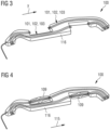
- Figure 3 shows the drive cable holder 100 as an independent component.
- the drive cable holder 100 is in Figure 3 shown without component 110.
- the drive cable holder 100 is manufactured in the mold 105 as a separate component and only subsequently attached to the component 110.
- corresponding fastening tabs are provided on the drive cable holder 100 and in particular on the holding body 116.
- FIG 4 shows the drive cable holder 100 according to a further exemplary embodiment.
- the drive cable holder 100 has brackets 109.
- the holders 109 are used in particular to attach one or more drives to the drive cable holder 100.
- the holders 109 are in particular connected to the holding body 116 in a materially bonded manner. It is therefore possible, for example, to form the drive cable holder 100 with the holder 109 and the guide tubes 101, 102, 103 directly on the component 110.
- the drive is in particular an electric drive and has, for example, an electric motor.
- the electric motor When ready for operation, the electric motor is in engagement with the drive cable 104, so that the drive can move the drive cable 104 relative to the corresponding guide tube 101, 102, 103 along the main direction of expansion 115.
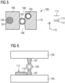
- Figure 5 shows a cross section transverse to the main extension direction 115 of the drive cable holder 100 according to an exemplary embodiment.
- the guide tubes 101, 102, 103 are arranged offset from one another along a Z direction.
- the Z direction is arranged transversely to the main propagation direction 115 and corresponds to the vertical in the normal operating position.
- the guide tube 102 in the normal operating position, is arranged in sections in a plane 112 closest to the ground.
- the guide tube 101 is arranged at least in sections in a plane 113 which is spaced apart from the plane 112 along the Z direction.
- the guide tube 103 is arranged at least in sections in a plane 114 which runs along the Z direction is spaced from the plane 113 and from the plane 112.
- the guide tubes 101, 102, 103 are each held at certain points by holding elements 107 ( Figure 6 ) held.
- free accesses 108 to the guide tubes 101, 102, 103 are formed at the points that correspond to the positions of the holding elements 107. However, these are only formed in a small proportion of the guide tubes 101, 102, 103, so that the holding body 116 provides sufficient support for the guide tubes 101, 102, 103.
- inserts made of metal or other rigid materials can be foamed into the holding body 116. Stabilization of the holding body 116 is therefore possible, for example. It is also possible to achieve the necessary compressive strength and creep resistance at specified locations using the inserts.
- the holding body 116 is designed, in particular from the plastic foam, to be so elastic and energy-absorbing that the foam body of the holding body 116 acts as an absorber to achieve predetermined head impact values (HIC) in the area of the vehicle roof 200 and in particular in the area of the component 201.
- HIC head impact values
- Figure 6 shows a schematic representation of the mold 105 according to an exemplary embodiment.
- the component 110 is used together with the guide tube 102 and, if necessary additional guide tubes are introduced into the mold 105.
- the guide tube 102 is held in a predetermined position relative to the component 110 by the holding elements 107.
- the inner walls of the mold 105 have the shape that the holding body 116 should later have.
- further elements such as inserts and/or the holder 109 or several holders 109 are introduced into the mold 105.
- the plastic to be foamed which consists, for example, of several components, is introduced into the mold 105.
- the plastic 106 is introduced into the mold 105 under a low pressure of less than 10 bar, in particular under a pressure between 1 bar and 6 bar. There the components react and foam up to form polyurethane. The plastic 106 spreads out so that it surrounds the guide tube 102 and forms the cohesive connection with the component 110, particularly on the surface 111.
Landscapes
- Engineering & Computer Science (AREA)
- Mechanical Engineering (AREA)
- Manufacturing & Machinery (AREA)
- Chemical & Material Sciences (AREA)
- Combustion & Propulsion (AREA)
- Transportation (AREA)
- Architecture (AREA)
- Civil Engineering (AREA)
- Structural Engineering (AREA)
- Injection Moulding Of Plastics Or The Like (AREA)
- Moulds For Moulding Plastics Or The Like (AREA)
- Supports For Pipes And Cables (AREA)
Description
- Es wird ein Verfahren zum Herstellen einer Antriebskabelhalterung für ein Fahrzeugdach angegeben. Außerdem wird ein Bauteil für ein Fahrzeugdach angegeben, dass eine Antriebskabelhalterung aufweist.
- Ein Kraftfahrzeug kann eine Dachöffnung aufweisen, die mittels eines beweglichen Deckels verschließbar und zumindest teilweise freigebbar ist. Beispielsweise wird die Bewegung des Deckels mittels eines Antriebs angetrieben, der mittels eines Antriebskabels mit dem Deckel gekoppelt ist. Auch ist es möglich, ein Rollo in einem Kraftfahrzeug vorzusehen, dass mittels eines Antriebs und eines Antriebskabels bewegbar ist. Das Antriebskabel ist beispielsweise in einem Führungsrohr geführt wie in der
DE 101 44 742 A1 beschrieben. - Die
DE 201 22 831 U1 betrifft ein Antriebskabel, das in einem Kabelrohr geführt ist, welches in einen Trägerrahmen eingeschäumt ist. -
US 2004/169400 A1 beschreibt ein Fahrzeugdachmodul, das fest mit einem Karosserierahmen des Fahrzeugs verbunden ist. -
DE 10 2015 119 405 A1 betrifft ein Schiebedachmodul mit einem Querteil, an dem eine Antriebsvorrichtung angeordnet ist. -
DE 100 39 522 A1 betrifft ein Sonnenrollo, das mittels in eine rahmenartig geformte Innenschale eingeschäumter Elemente an der Innenschale gehalten ist. - Es ist wünschenswert, ein Verfahren zum Herstellen einer Antriebskabelhalterung für ein Fahrzeugdach anzugeben, dass eine einfache Herstellung mit einem guten Integrationsgrad aufweist. Es ist zudem wünschenswert, ein Bauteil für ein Fahrzeugdach anzugeben, dass eine Antriebskabelhalterung aufweist, wobei das Bauteil kostengünstig und vergleichsweise einfach herstellbar ist.
- Die Erfindung betriff ein Verfahren mit den Merkmalen gemäß Anspruch 1 und ein Bauteil mit den Merkmalen gemäß Anspruch 8.
- Erfindungsgemäß umfasst ein Verfahren zum Herstellen einer Antriebskabelhalterung für ein Fahrzeugdach ein Bereitstellen eines Bauteils für das Fahrzeugdach. Das Bauteil wird in einem Formwerkzeug positioniert. Ein Führungsrohr für ein Antriebskabel wird bereitgestellt. Das Führungsrohr wird in dem Formwerkzeug positioniert. Insbesondere werden das Führungsrohr und das Bauteil relativ zueinander und relativ zu dem Formwerkzeug positioniert, sodass vorgegebene Positionen erreicht werden. Ein Kunststoff wird in das Formwerkzeug eingebracht. Der Kunststoff umgibt im Formwerkzeug das Führungsrohr zumindest abschnittsweise radial vollständig. Der Kunststoff gelangt im Formwerkzeug in Kontakt mit einer Oberfläche des Bauteils. Dadurch wird die Antriebskabelhalterung ausgebildet, die an dem Bauteil befestigt ist. Insbesondere ist die Antriebskabelhalterung ausgebildet, nachdem der Kunststoff ausgehärtet ist.
- Das Verfahren ermöglicht ein unmittelbares Anbinden des Führungsrohres an dem Bauteil. Auf weitere Befestigungselemente wie Nieten oder Schrauben oder Klebeverbindungen kann verzichtet werden. Zudem reichen wenige Verfahrensschritte aus. Im Vergleich zu herkömmlichen Herstellungsverfahren, bei denen das Führungsrohr in spritzgießtechnisch hergestellten Kunststoffteilen nachträglich befestigt wird, werden Verfahrensschritte und damit Kosten eingespart. Zudem werden keine Hilfsmittel benötigt, die herkömmlich zum Einführen der Rohre in das Kunststoffteil nötig sind. Die Antriebskabelhalterung ist zudem platzsparender als herkömmliche Kunststoffteile. Zudem weist die Antriebskabelhalterung einen vergleichsweise geringen Bauraumbedarf auf. Somit kann beispielsweise bei einem transparenten Fahrzeugdach die Durchsicht vergrößert werden.
- Erfindungsgemäß wird ein Halteelement zum Halten des Führungsrohres in dem Formwerkzeug bereitgestellt. Das Halteelement wird nach dem Einbringen des Kunststoffs entfernt. Dadurch wird ein freier Zugang zu dem Führungsrohr an einer zu dem Halteelement korrespondierten Position der Antriebskabelhalterung ausgebildet. Die Halterung des Führungsrohrs in dem Formwerkzeug ist nur in kurzen Abschnitten erforderlich, in denen die Halteelemente angeordnet werden. Zwischen den Halteelementen ist das Führungsrohr im Formwerkzeug frei zugänglich. Folglich ist in den Bereichen außerhalb der Halteelemente das radial vollständige Umgeben des Führungsrohrs mit dem Kunststoff möglich. An den Halteelementen ist das Führungsrohr nicht vollständig von dem Kunststoff umgeben, sondern nur teilweise. Somit bleibt der freie Zugang, der jedoch auf die Stabilität der Antriebskabelhalterung keine negativen Einflüsse hat.
- Gemäß zumindest einer Ausführungsform wird eine Halterung für einen Antrieb bereitgestellt. Die Halterung wird in dem Formwerkzeug vor dem Einbringen des Kunststoffs positioniert. Der Kunststoff wird in das Formwerkzeug eingebracht, sodass der Kunststoff die Halterung hält, wenn die Antriebshalterung ausgebildet ist. Die Halterung wird insbesondere relativ zu dem Bauteil und dem Führungsrohr an einer vorgegebenen Position positioniert, an der in der fertigen Antriebskabelhalterung der Antrieb montiert werden soll. Der Antriebs ist beispielsweise ein elektrischer Antrieb und weist beispielsweise einen elektrischen Motor auf. Der elektrische Motor ist im betriebsfertigen Zustand, insbesondere so in Kontakt mit einem Antriebskabel, das in dem Führungsrohr geführt ist, dass der Antrieb das Führungskabel entlang dem Führungsrohr bewegen kann.
- Gemäß zumindest einer Ausführungsform wird eine stoffschlüssige Verbindung zwischen dem Kunststoff und dem Bauteil zum Befestigen der Antriebskabelhalterung an dem Bauteil ausgebildet. Insbesondere wird der Kunststoff in dem Formwerkzeug so eingebracht, dass sich die stoffschlüssige Verbindung ausbildet. Somit ist es möglich, auf weitere mechanische Verbindungen zum Halten der Antriebskabelhalterung an dem Bauteil zu verzichten.
- Gemäß zumindest einer Ausführungsform wird eine Mehrzahl von Führungsrohren bereitgestellt, die jeweils ausgebildet sind, ein Antriebskabel zu führen. Die Mehrzahl der Führungsrohre wird in dem Formwerkzeug zumindest teilweise in unterschiedlichen Ebenen positioniert. Die Ebenen sind parallel zu einer Haupterstreckungsrichtung der Führungsrohre beabstandet zueinander. Insbesondere sind die Führungsrohre relativ zueinander im betriebsfertigen Zustand vertikal in den unterschiedlichen Ebenen angeordnet. Somit ist ein geringer Bauraumbedarf für die Antriebskabelhalterung realisierbar. Zudem ist ein enger Abstand der Führungsrohre zueinander realisierbar.
- Gemäß zumindest einer Ausführungsform werden die Führungsrohre in dem Formwerkzeug zumindest teilweise überlappend positioniert. Somit sind ein Überkreuzen und ein Übereinanderanordnen der Führungsrohre möglich. Dadurch wird ein geringer Bauraumbedarf der Antriebskabelhalterung realisiert.
- Gemäß zumindest einer Ausführungsform wird das Antriebskabel bereitgestellt. Das Antriebskabel wird nach dem Ausbilden der Antriebskabelhalterung in das Führungsrohr eingeführt. Es ist möglich, zunächst die Antriebskabelhalterung an dem Bauteil auszubilden, die das Führungsrohr oder mehrere Führungsrohre aufweist. Nachträglich kann das Antriebskabel oder mehrere Antriebskabel einfach in die jeweiligen Führungsrohre eingebracht werden.
- Gemäß zumindest einer Ausführungsform umfasst das Ausbilden der Antriebskabelhalterung ein Schäumverfahren. Insbesondere wird der Kunststoff gegen dem Formwerkzeug aufgeschäumt. Der Kunststoff ist beispielsweise ein Polyurethan. Das Führungsrohr wird in dem Formwerkzeug von dem Kunststoff umschäumt. Beispielsweise wird ein sogenanntes RIM-Verfahren (Reaktion Injektion Moulding) verwendet oder ein anderes Niederdruckverfahren. Beispielsweise werden zwei unterschiedliche Komponenten, beispielsweise Isocyanat und Polyol, in flüssiger Form in einen Gegenstrommischkopf eingebracht, homogenisiert und unter einem geringen Druck von beispielsweise bis zu maximal 6 Bar in das Formwerkzeug eingebracht. Dort reagieren die Komponenten zu Polyurethan. Aufgrund des geringen Drucks, der bei dem Schäumverfahren eingesetzt wird, wird das Führungsrohr nicht verformt. Das Führungsrohr ist beispielsweise ein Kunststoffrohr. Somit ist es möglich, ein biegeelastisches, relativ dünnwandiges Führungsrohr zu verwenden. Die niedrigen Innendrücke im Formwerkzeug vermeiden ein Nachgeben und Verformen des Führungsrohrs beim Ausbilden der Antriebskabelhalterung.
- Erfindungsgemäß weist ein Bauteil für ein Fahrzeugdach eine Antriebskabelhalterung auf. Beispielsweise ist das Bauteil mit der Antriebskabelhalterung gemäß einem hier beschriebenen Herstellungsverfahren hergestellt. Die Antriebskabelhalterung weist einen Haltekörper aus einem Kunststoff auf. Die Antriebskabelhalterung weist ein Führungsrohr auf. Das Führungsrohr ist zumindest abschnittsweise radial vollständig von dem Haltekörper umgeben. Der Haltekörper ist einstückig ausgebildet und stoffschlüssig mit dem Bauteil verbunden. Beispielsweise ist der Haltekörper aus einem aufgeschäumten Kunststoff wie einem Polyurethan gebildet.
- Die für das Verfahren erläuterten Merkmale und Vorteile gelten auch für das Bauteil und umgekehrt.
- Das Bauteil mit dem direkt angeschäumten Haltekörper ermöglicht einen vergleichsweise geringen Bauraumbedarf und dabei eine zuverlässige Abstützung des Führungsrohrs. Zudem ist eine flexible Ausgestaltung der Lage des Führungsrohrs relativ zu dem Bauteil möglich. Es sind keine weiteren Befestigungselemente nötig, um die Antriebskabelhalterung an dem Bauteil zu befestigen. Somit ist ein hoher Integrationsgrad erreichbar.
- Gemäß zumindest einer Ausführungsform weist das Bauteil eine Halterung für einen Antrieb auf, die von dem Haltekörper gehalten ist. Somit ist auch eine Schnittstelle zur Montage des Antriebs in die Antriebskabelhalterung integriert.
- Gemäß zumindest einer Ausführungsform ist der Haltekörper so elastisch ausgebildet, dass die Antriebskabelhalterung einen Kopfverletzungsfaktor von unter 1500 aufweist. Insbesondere durch die Verwendung eines PUR-Schaums ist es möglich, den Haltekörper mit einer elastischen, energieabsorbierenden Härte auszubilden, sodass der Haltekörper aus dem Kunststoffschaum als Absorber ausgebildet ist. Somit ist der Kopfverletzungsfaktor von unter 1500 im Fahrzeugdachbereich realisierbar. Der Kopfverletzungsfaktor (HIC, Head Injury Criterion) ist beispielsweise gesetzlich vorgegeben. Beispielsweise ist es möglich, mittels des Haltekörpers aus aufgeschäumtem Kunststoff einen Kopfverletzungsfaktor von unter 1000 zu ermöglichen. Somit dient die Antriebskabelhalterung sowohl zum Halten des Führungsrohrs und gegebenenfalls des Antriebs als auch als Absorber um im Fahrzeugdachbereich den geforderten Kopfverletzungsfaktor zu ermöglichen. Somit lassen sich ansonsten erforderliche zusätzliche Absorberschaumteile einsparen, wodurch Montagekosten und Bauteilkosten reduziert werden können. Zudem ist so ein hoher Integrationsgrad erreichbar.
- Gemäß zumindest einer Ausführungsform weist das Bauteil eine Mehrzahl von Führungsrohren auf. Die Führungsrohre sind in der Antriebskabelhalterung zumindest teilweise in unterschiedlichen Ebenen angeordnet. Die Ebenen sind jeweils parallel zu einer Haupterstreckungsrichtung der Führungsrohre beabstandet zueinander. Somit ist in normaler Betriebsposition eine Anordnung der Führungsrohre vertikal und horizontal beabstandet zueinander möglich. Beispielsweise überlappen und/oder überkreuzen sich die Führungsrohre zumindest teilweise. Somit lässt sich Bauraum einsparen.
- Gemäß zumindest einer Ausführungsform ist das Bauteil ein Rahmenelement für eine Dachöffnung des Fahrzeugdachs. Insbesondere ist das Bauteil das Rahmenelement, das quer zur Hauptfahrtrichtung des Fahrzeugs entlang der Windschutzscheibe angeordnet ist.
- Weitere Vorteile, Merkmale und Weiterbildungen ergeben sich aus den nachfolgenden, in Zusammenhang mit den Figuren erläuterten Ausführungsbeispielen. Gleiche, gleichartige oder gleichwirkende Elemente können figurenübergreifend mit den gleichen Bezugszeichen versehen sein. Es zeigen:
-
Figur 1 eine schematische Darstellung eines Kraftfahrzeug gemäß einem Ausführungsbeispiel, -
Figur 2 eine schematische Darstellung eines Bauteils gemäß einem Ausführungsbeispiel, -
Figur 3 eine schematische Darstellung einer Antriebskabelhalterung gemäß einem Ausführungsbeispiel, -
Figur 4 eine schematische Darstellung einer Antriebskabelhalterung gemäß einem Ausführungsbeispiel, -
Figur 5 eine schematische Darstellung eines Querschnitts durch eine Antriebskabelhalterung gemäß einem Ausführungsbeispiel, und -
Figur 6 eine schematische Darstellung einer Herstellung gemäß einem Ausführungsbeispiel. -
Figur 1 zeigt ein Kraftfahrzeug mit einem Fahrzeugdach 200. Das Fahrzeugdach weist eine Dachöffnung 201 auf, die mittels eines Deckels 202 verschließbar ist. Gemäß Ausführungsbeispiel ist der Deckel 202 relativ zum übrigen Fahrzeugdach 200 beweglich, beispielsweise nach Art eines Schiebedachs. Gemäß weiteren Ausführungsformen ist der Deckel 202 ein sogenanntes Festdachelement, das relativ zum übrigen Fahrzeugdach 200 unbeweglich mit dem Kraftfahrzeug gekoppelt ist. - An der Dachöffnung 201 ist ein Bauteil 101 angeordnet, dass insbesondere ein Rahmenelement ist. Der Rahmen mit dem Bauteil 110 dient beispielsweise zum Führen und Halten des Deckels 202. Alternativ oder zusätzlich dient der Rahmen mit dem Bauteil 110 zum Führen und Halten eines Rollos (nicht explizit gezeigt).
-
Figur 2 zeigt das Bauteil 110 gemäß einem Ausführungsbeispiel. Das Bauteil 110 weist eine Antriebskabelhalterung 100 auf. Die Antriebskabelhalterung 100 ist unmittelbar an eine Oberfläche 111 des Bauteils 110 angeschäumt. Die Antriebskabelhalterung 100 weist einen Haltekörper 116 aus Kunststoff auf. Der Haltekörper 116 ist beispielsweise aus Polyurethan gebildet. Der Haltekörper 116 ist stoffschlüssig mit dem Bauteil 110 verbunden. - Die Antriebskabelhalterung 100 weist Führungsrohre 101, 102, 103 auf. Die Führungsrohre 101, 102, 103 sind jeweils dazu ausgebildet, ein Antriebskabel 104 (
Figur 5 ) zu führen. Gemäß weiteren Ausführungsbeispielen sind mehr oder weniger Führungsrohre vorgesehen. - Die Führungsrohre 101, 102, 103 sind beispielsweise jeweils Kunststoffrohre. Die Führungsrohre 101, 102, 103 sind stoffschlüssig mit dem Haltekörper 116 verbunden. Der Haltekörper 116 umgibt die Führungsrohre 101, 102, 103 abschnittsweise vollständig, um die Führungsrohre 101, 102, 103 zu halten. Insbesondere quer zu einer Haupterstreckungsrichtung 115 sind die Führungsrohre 101, 102, 103 jeweils abschnittsweise radial vollständig von dem Haltekörper 116 umgeben.
- Der Haltekörper 116 ist insbesondere aus einem aufgeschäumten Kunststoff 106 (
Figur 5 ) ausgebildet. Somit ist es möglich, auf spritzgießtechnisch hergestellte Kunststoffteile zu verzichten. Durch das Befestigen der Führungsrohre 101, 102, 103 unmittelbar in dem aufgeschäumten Kunststoff 106 des Haltekörpers 116 sind die Führungsrohre 101, 102, 103 gehalten, ohne dass sie nachträglich in den Haltekörper 116 eingeführt werden müssen. Somit kann auf bauliche Hilfsmittel zum nachträglichen Einführen der Führungsrohre verzichtet werden. Somit ein geringerer Bauraumbedarf realisierbar und die Herstellung und Montage insgesamt weniger aufwendig und damit effizienter. - Der Bauraum, der für das Bauteil 110 und die Antriebskabelhalterung 100 benötigt wird, wird reduziert. Somit wird die Durchsicht bei einem transparenten Deckel 202 erhöht. Die von dem Bauteil 110 belegte Fläche innerhalb der Dachöffnung 201 wird reduziert.
- Die Führungsrohre 101, 102, 103 können quer zur Hauptausbreitungsrichtung 115 versetzt angeordnet werden (
Figur 5 ). Zudem ist es möglich, die Führungsrohre 101, 102, 103 in geringem Abstand zueinander, überlappend und/oder überkreuzend anzuordnen. Somit ist es möglich, eine Vielzahl von Führungsrohren 101, 102, 103 in engem Abstand zueinander und übereinander anzuordnen und dabei einen flexiblen Gestaltungsspielraum zu realisieren. Der Haltekörper 116 stützt dabei nach dem Aushärten des Kunststoffs 106 die Führungsrohre 101, 102, 103 ausreichend ab, sodass im Betrieb eine verlässliche Führung der Antriebskabel 104 möglich ist. Zug- und/oder Druckkräfte werden verlässlich abgestützt. - Der Haltekörper 116 ist insbesondere nicht mittels eines Spritzgussverfahrens hergestellt, bei dem vergleichsweise hohe Innendrücke in dem Formwerkzeug herrschen. Die vergleichsweise hohen Innendrücke würden dazu führen, dass die vergleichsweise dünnwandigen Führungsrohre 101, 102, 103 nachgeben und verformt würden. Der Haltekörper 116 ist mittels eines Schaumverfahrens hergestellt, bei dem in einem Formwerkzeug 105 (
Figur 6 ) vergleichsweise geringe Drücke von bis zu maximal 6 Bar herrschen. Beim Aufschäumen der Komponenten in dem Formwerkzeug 105 breitet sich der Kunststoff 106 so aus, dass er die Führungsrohre 101, 102, 103 ausreichend umgibt, um diese zu halten. Dabei ist es auch möglich, drei, vier oder mehr Rohre übereinander mit geringem Abstand anzuordnen, da der Kunststoff auch derartige Geometrien umgeben kann mittels des Aufschäumens. Die Führungsrohre 101, 102, 103 müssen während dem Schäumverfahren lediglich an einigen wenigen Stellen in dem Formwerkzeug 105 gehalten werden. An den übrigen Bereichen umgibt der Kunststoff 106 nach dem Aushärten die Führungsrohre 101, 102, 103 radial vollständig. - Somit ist es möglich, bei relativ niedrigem Verarbeitungsdruck übereinanderliegende dünnwandige Führungsrohre 101, 102, 103 vollflächig einzuschließen und miteinander zu verbinden. Durch die nahezu vollflächige Umgebung mit dem Kunststoff 106 wird ein Ausknicken der Führungsrohre 101, 102, 103 unter Last verhindert. Es ist möglich, ein vergleichsweise sehr geringes Bauraummaß für mehrere, eng aneinander und/oder übereinanderliegende Führungsrohre 101, 102, 103 zu realisieren.
-
Figur 3 zeigt die Antriebskabelhalterung 100 als eigenständiges Bauelement. Die Antriebskabelhalterung 100 ist inFigur 3 ohne das Bauteil 110 dargestellt. Beispielsweise wird die Antriebskabelhalterung 100 in dem Formwerkzeug 105 als separates Bauteil gefertigt und erst nachträglich an dem Bauteil 110 befestigt. Dazu werden an der Antriebskabelhalterung 100 und insbesondere an dem Haltekörper 116 entsprechende Befestigungslaschen vorgesehen. -
Figur 4 zeigt die Antriebskabelhalterung 100 gemäß einem weiteren Ausführungsbeispiel. Die Antriebskabelhalterung 100 weist Halterungen 109 auf. Die Halterungen 109 dienen insbesondere zum Befestigen eines Antriebs oder mehrerer Antriebe an der Antriebskabelhalterung 100. Die Halterungen 109 sind insbesondere stoffschlüssig mit dem Haltekörper 116 verbunden. Somit ist es beispielsweise möglich, die Antriebskabelhalterung 100 mit den Halterung 109 und den Führungsrohren 101, 102, 103 unmittelbar an dem Bauteil 110 anzuformen. - Der Antrieb ist insbesondere ein elektrischer Antrieb und weist beispielsweise einen Elektromotor auf. Der Elektromotor ist im betriebsfertigen Zustand im Eingriff mit dem Antriebskabel 104, sodass der Antrieb die Antriebskabel 104 relativ zu dem entsprechenden Führungsrohr 101, 102, 103 entlang der Hauptausdehnungsrichtung 115 verschieben kann.
-
Figur 5 zeigt einen Querschnitt quer zur Haupterstreckungsrichtung 115 der Antriebskabelhalterung 100 gemäß einem Ausführungsbeispiel. Die Führungsrohre 101, 102, 103 sind entlang einer Z-Richtung versetzt zueinander angeordnet. Beispielsweise ist die Z-Richtung quer zur Hauptausbreitungsrichtung 115 angeordnet und entspricht in normaler Betriebsposition der Vertikalen. Beispielsweise ist das Führungsrohr 102 im gezeigten Ausführungsbeispiel in normaler Betriebsposition am nächsten am Boden abschnittsweise in einer Ebene 112 angeordnet. Das Führungsrohr 101 ist zumindest abschnittsweise in einer Ebene 113 angeordnet, die entlang der Z-Richtung beabstandet zur Ebene 112 ist. Das Führungsrohr 103 ist zumindest abschnittsweise in einer Ebene 114 angeordnet, die entlang der Z-Richtung beabstandet zu der Ebene 113 und zu der Ebene 112 ist. - In dem Formwerkzeug 105 werden die Führungsrohre 101, 102, 103 jeweils punktuell von Halteelementen 107 (
Figur 6 ) gehalten. In dem fertigen Haltekörper 116 sind an den Stellen, die mit den Positionen der Halteelemente 107 korrespondieren, freie Zugänge 108 zu den Führungsrohren 101, 102, 103 ausgebildet. Diese sind jedoch nur in einem geringen Anteil der Führungsrohre 101, 102, 103 ausgebildet, sodass durch den Haltekörper 116 eine ausreichende Abstützung der Führungsrohre 101, 102, 103 gegeben ist. - Gemäß Ausführungsbeispielen können Einleger beispielsweise aus Metall oder anderen steifen Materialien mit in den Haltekörper 116 eingeschäumt werden. Somit ist beispielsweise eine Stabilisierung des Haltekörpers 116 möglich. Zudem ist es möglich, mittels den Einlegern eine nötige Druckfestigkeit und Kriechfestigkeit an vorgegebenen Stellen zu erreichen.
- Der Haltekörper 116 ist insbesondere aus dem Kunststoffschaum so elastisch und energieabsorbierend ausgebildet, dass der Schaumkörper des Haltekörpers 116 als Absorber zur Erlangung von vorgegebenen Kopfaufprallwerten (HIC) im Bereich des Fahrzeugdachs 200 und insbesondere im Bereich des Bauteils 201 wirksam wird. Somit lassen sich die ansonsten erforderlichen zusätzlichen Absorberbauteile einsparen, wodurch weitere Bauteilkosten und Montagekosten vermieden werden können.
-
Figur 6 zeigt eine schematische Darstellung des Formwerkzeugs 105 gemäß einem Ausführungsführungsbeispiel. Das Bauteil 110 wird gemeinsam mit dem Führungsrohr 102 und gegebenenfalls weiteren Führungsrohren in das Formwerkzeug 105 eingebracht. Das Führungsrohr 102 wird von den Halteelementen 107 relativ zu dem Bauteil 110 in einer vorgegebenen Position gehalten. Die Innenwände des Formwerkzeugs 105 weisen die Form auf, die später der Haltekörper 116 aufweisen soll. Gemäß weiteren Ausführungsformen werden weitere Elemente wie Einleger und/oder die Halterung 109 oder mehrere Halterungen 109 in das Formwerkzeug 105 eingebracht. Nachfolgend wird das auszuschäumende Kunststoff, das beispielsweise aus mehreren Komponenten besteht, in das Formwerkzeug 105 eingebracht. Insbesondere wird der Kunststoff 106 unter einem geringen Druck von unter 10 Bar, insbesondere unter einem Druck zwischen 1 Bar und 6 Bar in das Formwerkzeug 105 eingebracht. Dort reagieren die Komponenten und schäumen sich zu Polyurethan auf. Dabei breitet sich der Kunststoff 106 so aus, dass er das Führungsrohr 102 umgibt und mit dem Bauteil 110 insbesondere an der Oberfläche 111 die stoffschlüssige Verbindung ausbildet. - Somit ist es möglich, bei relativ niedrigem Verarbeitungsdruck übereinanderliegende dünnwandige Führungsrohre 101, 102, 103 vollflächig einzuschließen und miteinander zu verbinden. Durch das unmittelbare Anschäumen der Antriebskabelhalterung 100 an dem Bauteil 110 sind eine kostengünstige Herstellung und ein hoher Integrationsgrad ermöglicht.
-
- 100 Antriebskabelhalterung
- 101, 102, 103 Führungsrohr
- 104 Antriebskabel
- 105 Formwerkzeug
- 106 Kunststoff
- 107 Halteelement
- 108 Zugang
- 109 Halterung
- 110 Bauteil
- 111 Oberfläche
- 112, 113, 114 Ebene
- 115 Haupterstreckungsrichtung
- 116 Haltekörper
- 200 Fahrzeugdach
- 201 Dachöffnung
- 202 Deckel
Claims (13)
- Verfahren zum Herstellen einer Antriebskabelhalterung (100) für ein Fahrzeugdach (200), umfassend:- Bereitstellen eines Bauteils (110) für das Fahrzeugdach (200),- Positionieren des Bauteils (110) in einem Formwerkzeug (105),- Bereitstellen eines Führungsrohres (101) für ein Antriebskabel (104),- Positionieren des Führungsrohres (101) in dem Formwerkzeug (105),- Einbringen eines Kunststoffs (106) in das Formwerkzeug (105), sodass der Kunststoff (106) das Führungsrohr (101) zumindest abschnittsweise radial vollständig umgibt und sodass der Kunststoff (106) in Kontakt mit einer Oberfläche (111) des Bauteils (110) gelangt, und dadurch- Ausbilden der Antriebskabelhalterung (100), die an dem Bauteil (110) befestigt ist, gekennzeichnet durch:- Bereitstellen eines Halteelements (107) zum Halten des Führungsrohres (101) in dem Formwerkzeug (105),- Entfernen des Halteelements (107) nach dem Einbringen des Kunststoffs (106), und dadurch- Ausbilden eines freien Zugangs (108) zu dem Führungsrohr (101) an einer zu dem Halteelement (107) korrespondierenden Position der Antriebskabelhalterung (100).
- Verfahren nach Anspruch 1, umfassend:- Bereitstellen einer Halterung (109) für einen Antrieb,- Positionieren der Halterung (109) in dem Formwerkzeug (105) vor dem Einbringen des Kunststoffs (106),- Einbringen des Kunststoffs (106) in das Formwerkzeug (105), sodass der Kunststoff (106) die Halterung (109) hält, wenn die Antriebskabelhalterung (100) ausgebildet ist.
- Verfahren nach Anspruch 1 oder 2, umfassend:- Ausbilden einer stoffschlüssigen Verbindung zwischen dem Kunststoff (106) und dem Bauteil (110) zum Befestigen der Antriebskabelhalterung (100) an dem Bauteil (110).
- Verfahren nach einem der Ansprüche 1 bis 3, umfassend:- Bereitstellen einer Mehrzahl von Führungsrohren (101, 102, 103) jeweils für ein Antriebskabel (104),- Positionieren der Mehrzahl von Führungsrohren (101, 102, 103) in dem Formwerkzeug (105) zumindest teilweise in unterschiedlichen Ebenen (112, 113, 114), die jeweils parallel zu einer Haupterstreckungsrichtung (115) der Führungsrohre (101, 102, 103) beabstandet zueinander sind.
- Verfahren nach Anspruch 4, umfassend:- Positionieren der Mehrzahl von Führungsrohren (101, 102, 103) in dem Formwerkzeug (105) zumindest teilweise überlappend.
- Verfahren nach einem der Ansprüche 1 bis 5, umfassend:- Bereitstellen des Antriebskabels (104),- Einführen des Antriebskabels (104) in das Führungsrohr (101, 102, 103) nach dem Ausbilden der Antriebkabelhalterung (100) .
- Verfahren nach einem der Ansprüche 1 bis 6, bei dem das Ausbilden der Antriebskabelhalterung (100) ein Schäumverfahren umfasst.
- Bauteil für ein Fahrzeugdach (200), aufweisend eine Antriebskabelhalterung (100), die aufweist:- einen Haltekörper (116) aus einem Kunststoff (106),- ein Führungsrohr (101), wobei- das Führungsrohr (101) zumindest abschnittsweise radial vollständig von dem Haltekörper (116) umgeben ist, und- der Haltekörper (116) einstückig ausgebildet ist und stoffschlüssig mit dem Bauteil (110) verbunden ist, gekennzeichnet dadurch, dass- in dem Haltekörper freie Zugänge (108) zu dem Führungsrohr (101) ausgebildet sind.
- Bauteil nach Anspruch 8, aufweisend eine Halterung (109) für einen Antrieb, die von dem Haltekörper (116) gehalten ist.
- Bauteil nach Anspruch 8 oder 9, bei dem der Haltekörper (116) so elastisch ausgebildet ist, dass die Antriebkabelhalterung (100) einen Kopf-Verletzungs-Faktor von unter 1500 aufweist.
- Bauteil nach einem der Ansprüche 9 bis 10, aufweisend eine Mehrzahl von Führungsrohren (101, 102, 103), wobei die Führungsrohre (101, 102, 103) in der Antriebskabelhalterung (100) zumindest teilweise in unterschiedlichen Ebenen (112, 113, 114) angeordnet sind, die jeweils parallel zu einer Haupterstreckungsrichtung (115) der Führungsrohre (101, 102, 103) beabstandet zueinander sind.
- Bauteil nach Anspruch 11, bei dem die Führungsrohre (101, 102, 103) in der Antriebskabelhalterung (100) zumindest teilweise überlappend.
- Bauteil nach einem der Ansprüche 9 bis 12, das ein Rahmenelement für eine Dachöffnung (201) des Fahrzeugdachs (200) ist.
Applications Claiming Priority (2)
| Application Number | Priority Date | Filing Date | Title |
|---|---|---|---|
| DE102018110124.4A DE102018110124A1 (de) | 2018-04-26 | 2018-04-26 | Verfahren zum Herstellen einer Antriebskabelhalterung für ein Fahrzeugdach und Bauteil für ein Fahrzeugdach |
| PCT/EP2019/060113 WO2019206812A1 (de) | 2018-04-26 | 2019-04-18 | Verfahren zum herstellen einer antriebskabelhalterung für ein fahrzeugdach und bauteil für ein fahrzeugdach |
Publications (2)
| Publication Number | Publication Date |
|---|---|
| EP3784510A1 EP3784510A1 (de) | 2021-03-03 |
| EP3784510B1 true EP3784510B1 (de) | 2024-03-13 |
Family
ID=66334430
Family Applications (1)
| Application Number | Title | Priority Date | Filing Date |
|---|---|---|---|
| EP19720506.5A Active EP3784510B1 (de) | 2018-04-26 | 2019-04-18 | Verfahren zum herstellen einer antriebskabelhalterung für ein fahrzeugdach und bauteil für ein fahrzeugdach |
Country Status (5)
| Country | Link |
|---|---|
| US (1) | US12077040B2 (de) |
| EP (1) | EP3784510B1 (de) |
| CN (1) | CN111902302B (de) |
| DE (1) | DE102018110124A1 (de) |
| WO (1) | WO2019206812A1 (de) |
Families Citing this family (1)
| Publication number | Priority date | Publication date | Assignee | Title |
|---|---|---|---|---|
| DE102020133729B4 (de) * | 2020-12-16 | 2025-03-06 | Webasto SE | Verfahren zum Herstellen einer Antriebskabelhalterung für ein Fahrzeugdach und Bauteil für ein Fahrzeugdach |
Citations (1)
| Publication number | Priority date | Publication date | Assignee | Title |
|---|---|---|---|---|
| DE10039522A1 (de) * | 2000-08-08 | 2002-02-28 | Meritor Automotive Gmbh | Modulartiges Fahrzeugdach |
Family Cites Families (10)
| Publication number | Priority date | Publication date | Assignee | Title |
|---|---|---|---|---|
| DE3727719C2 (de) * | 1987-08-20 | 1994-07-21 | Webasto Ag Fahrzeugtechnik | Rahmenanordnung für ein Fahrzeugdach |
| DE20122834U1 (de) * | 2001-04-12 | 2008-03-27 | Voith Patent Gmbh | Auftragsvorrichtung |
| DE10144742C2 (de) | 2001-09-11 | 2003-06-26 | Arvinmeritor Gmbh | Rahmen für ein Fahrzeug-Schiebedach oder -Schiebehebedach |
| DE10150011B4 (de) * | 2001-10-11 | 2007-03-15 | Webasto Ag | Deckel für ein Fahrzeugdach und Verfahren zu dessen Herstellung |
| DE20122831U1 (de) * | 2001-12-28 | 2008-06-12 | Webasto Ag | Öffnungsfähiges Fahrzeugdach mit Antriebskabeln |
| DE10308582A1 (de) * | 2003-02-27 | 2004-09-30 | Arvinmeritor Gmbh | Verfahren zum Herstellen eines Fahrzeug-Karosserieteils |
| DE102004050107B4 (de) * | 2004-10-14 | 2008-08-21 | Webasto Ag | Fahrzeugdach |
| JP2011156938A (ja) * | 2010-01-29 | 2011-08-18 | Yachiyo Industry Co Ltd | 車両ルーフ構造 |
| DE102013210470B4 (de) | 2013-06-05 | 2017-11-02 | Bos Gmbh & Co. Kg | Antriebsübertragungssystem und Verfahren zur Montage eines derartigen Antriebsübertragungssystems |
| DE102015119405A1 (de) * | 2015-11-11 | 2017-05-11 | Roof Systems Germany Gmbh | Schiebedachmodul und Verfahren zur Herstellung des Schiebedachmoduls |
-
2018
- 2018-04-26 DE DE102018110124.4A patent/DE102018110124A1/de not_active Ceased
-
2019
- 2019-04-18 WO PCT/EP2019/060113 patent/WO2019206812A1/de not_active Ceased
- 2019-04-18 CN CN201980022112.8A patent/CN111902302B/zh active Active
- 2019-04-18 EP EP19720506.5A patent/EP3784510B1/de active Active
- 2019-04-18 US US16/969,731 patent/US12077040B2/en active Active
Patent Citations (1)
| Publication number | Priority date | Publication date | Assignee | Title |
|---|---|---|---|---|
| DE10039522A1 (de) * | 2000-08-08 | 2002-02-28 | Meritor Automotive Gmbh | Modulartiges Fahrzeugdach |
Non-Patent Citations (1)
| Title |
|---|
| KLEIVEN SVEIN: "A parametric study of energy absorbing foams for head injury prevention", RESEARCH GATE, 31 January 2007 (2007-01-31), pages 1 - 13, XP093023098, Retrieved from the Internet <URL:https://www.researchgate.net/publication/266286015_A_parametric_study_of_energy_absorbing_foams_for_head_injury_prevention> [retrieved on 20230213] * |
Also Published As
| Publication number | Publication date |
|---|---|
| US20210001698A1 (en) | 2021-01-07 |
| CN111902302B (zh) | 2024-05-28 |
| EP3784510A1 (de) | 2021-03-03 |
| CN111902302A (zh) | 2020-11-06 |
| DE102018110124A1 (de) | 2019-10-31 |
| WO2019206812A1 (de) | 2019-10-31 |
| US12077040B2 (en) | 2024-09-03 |
Similar Documents
| Publication | Publication Date | Title |
|---|---|---|
| EP2181016B1 (de) | Struktur für einen fahrzeugsitz | |
| EP2591193B1 (de) | Führungsschiene für einen fensterheber und türsystem für eine fahrzeugtür | |
| EP2459432B1 (de) | Baukastensystem und verfahren zum herstellen eines dachmoduls | |
| EP3221168B1 (de) | Rahmen eines fahrzeugdachs und dessen herstellung | |
| DE102011014989A1 (de) | Kunststoffbauelement eines Dachöffnungssystems | |
| DE10327839A1 (de) | Fahrzeugdachmodul | |
| EP2025424A1 (de) | Verfahren zur Herstellung eines rohrförmigen Tragprofils für einen Instrumententräger | |
| EP3784510B1 (de) | Verfahren zum herstellen einer antriebskabelhalterung für ein fahrzeugdach und bauteil für ein fahrzeugdach | |
| DE102007053961A1 (de) | Struktur für einen Fahrzeugsitz | |
| DE102011054866A1 (de) | Verfahren zur Herstellung eines warmumgeformten und pressgehärteten Kraftfahrzeugkarosseriebauteils sowie Kraftfahrzeugkarosseriebauteil | |
| EP1100667A1 (de) | Zentriereinrichtung für flache bauteile, insbesondere glastafeln | |
| EP4465309A1 (de) | Verfahren zur herstellung einer form und form zur herstellung eines kabelbaums | |
| DE102009058559A1 (de) | Halteanordnung eines Anbauteils an einem Kraftwagen sowie Verfahren zur Montage eines Anbauteils an einem Kraftwagen | |
| DE2826258A1 (de) | Verfahren zur herstellung einer sonnenblende | |
| DE10237756A1 (de) | Verfahren zum Herstellen eines höhenverstellbaren Fahrzeugfensters und höhenverstellbares Fahrzeugfenster | |
| DE102010014538B4 (de) | Querträger, insbesondere Instrumenten-Querträger | |
| DE102020133729B4 (de) | Verfahren zum Herstellen einer Antriebskabelhalterung für ein Fahrzeugdach und Bauteil für ein Fahrzeugdach | |
| DE102014218774A1 (de) | Kraftfahrzeugtür mit einem Hohlprofil und Verfahren zur Herstellung einer Kraftfahrzeugtür | |
| DE102010014537B4 (de) | Strukturbauteil für einen Kraftwagen und Verfahren zu dessen Herstellung | |
| DE202015105325U1 (de) | Formwerkzeug mit Werkzeugwand | |
| DE102012004955A1 (de) | Halteanordnung eines Kühlmoduls an einem Aufbauelement eines Kraftwagenaufbaus | |
| DE102023204240B4 (de) | Verfahren zur Montage eines Lautsprechergehäuses in einem Kraftfahrzeugbauteil, Lautsprechergehäuse und Kraftfahrzeugbauteil mit Lautsprechergehäuse | |
| DE102015202420A1 (de) | Türinnenverkleidung, Fahrzeugtür mit einer Türinnenverkleidung sowie Fahrzeug mit einer Fahrzeugtür | |
| DE102011011815A1 (de) | Halteanordnung eines Anbauteils an einem Kraftwagenteil | |
| DE102013201613A1 (de) | Verfahren und System zur Herstellung einer Baugruppe |
Legal Events
| Date | Code | Title | Description |
|---|---|---|---|
| STAA | Information on the status of an ep patent application or granted ep patent |
Free format text: STATUS: UNKNOWN |
|
| STAA | Information on the status of an ep patent application or granted ep patent |
Free format text: STATUS: THE INTERNATIONAL PUBLICATION HAS BEEN MADE |
|
| PUAI | Public reference made under article 153(3) epc to a published international application that has entered the european phase |
Free format text: ORIGINAL CODE: 0009012 |
|
| STAA | Information on the status of an ep patent application or granted ep patent |
Free format text: STATUS: REQUEST FOR EXAMINATION WAS MADE |
|
| 17P | Request for examination filed |
Effective date: 20200924 |
|
| AK | Designated contracting states |
Kind code of ref document: A1 Designated state(s): AL AT BE BG CH CY CZ DE DK EE ES FI FR GB GR HR HU IE IS IT LI LT LU LV MC MK MT NL NO PL PT RO RS SE SI SK SM TR |
|
| AX | Request for extension of the european patent |
Extension state: BA ME |
|
| DAV | Request for validation of the european patent (deleted) | ||
| DAX | Request for extension of the european patent (deleted) | ||
| STAA | Information on the status of an ep patent application or granted ep patent |
Free format text: STATUS: EXAMINATION IS IN PROGRESS |
|
| 17Q | First examination report despatched |
Effective date: 20211202 |
|
| GRAP | Despatch of communication of intention to grant a patent |
Free format text: ORIGINAL CODE: EPIDOSNIGR1 |
|
| STAA | Information on the status of an ep patent application or granted ep patent |
Free format text: STATUS: GRANT OF PATENT IS INTENDED |
|
| INTG | Intention to grant announced |
Effective date: 20231025 |
|
| GRAS | Grant fee paid |
Free format text: ORIGINAL CODE: EPIDOSNIGR3 |
|
| GRAA | (expected) grant |
Free format text: ORIGINAL CODE: 0009210 |
|
| STAA | Information on the status of an ep patent application or granted ep patent |
Free format text: STATUS: THE PATENT HAS BEEN GRANTED |
|
| AK | Designated contracting states |
Kind code of ref document: B1 Designated state(s): AL AT BE BG CH CY CZ DE DK EE ES FI FR GB GR HR HU IE IS IT LI LT LU LV MC MK MT NL NO PL PT RO RS SE SI SK SM TR |
|
| REG | Reference to a national code |
Ref country code: GB Ref legal event code: FG4D Free format text: NOT ENGLISH |
|
| REG | Reference to a national code |
Ref country code: CH Ref legal event code: EP |
|
| REG | Reference to a national code |
Ref country code: DE Ref legal event code: R096 Ref document number: 502019010792 Country of ref document: DE |
|
| REG | Reference to a national code |
Ref country code: IE Ref legal event code: FG4D Free format text: LANGUAGE OF EP DOCUMENT: GERMAN |
|
| PG25 | Lapsed in a contracting state [announced via postgrant information from national office to epo] |
Ref country code: LT Free format text: LAPSE BECAUSE OF FAILURE TO SUBMIT A TRANSLATION OF THE DESCRIPTION OR TO PAY THE FEE WITHIN THE PRESCRIBED TIME-LIMIT Effective date: 20240313 |
|
| REG | Reference to a national code |
Ref country code: LT Ref legal event code: MG9D |
|
| PG25 | Lapsed in a contracting state [announced via postgrant information from national office to epo] |
Ref country code: GR Free format text: LAPSE BECAUSE OF FAILURE TO SUBMIT A TRANSLATION OF THE DESCRIPTION OR TO PAY THE FEE WITHIN THE PRESCRIBED TIME-LIMIT Effective date: 20240614 |
|
| REG | Reference to a national code |
Ref country code: NL Ref legal event code: MP Effective date: 20240313 |
|
| PG25 | Lapsed in a contracting state [announced via postgrant information from national office to epo] |
Ref country code: HR Free format text: LAPSE BECAUSE OF FAILURE TO SUBMIT A TRANSLATION OF THE DESCRIPTION OR TO PAY THE FEE WITHIN THE PRESCRIBED TIME-LIMIT Effective date: 20240313 Ref country code: RS Free format text: LAPSE BECAUSE OF FAILURE TO SUBMIT A TRANSLATION OF THE DESCRIPTION OR TO PAY THE FEE WITHIN THE PRESCRIBED TIME-LIMIT Effective date: 20240613 |
|
| PG25 | Lapsed in a contracting state [announced via postgrant information from national office to epo] |
Ref country code: ES Free format text: LAPSE BECAUSE OF FAILURE TO SUBMIT A TRANSLATION OF THE DESCRIPTION OR TO PAY THE FEE WITHIN THE PRESCRIBED TIME-LIMIT Effective date: 20240313 |
|
| PG25 | Lapsed in a contracting state [announced via postgrant information from national office to epo] |
Ref country code: RS Free format text: LAPSE BECAUSE OF FAILURE TO SUBMIT A TRANSLATION OF THE DESCRIPTION OR TO PAY THE FEE WITHIN THE PRESCRIBED TIME-LIMIT Effective date: 20240613 Ref country code: NO Free format text: LAPSE BECAUSE OF FAILURE TO SUBMIT A TRANSLATION OF THE DESCRIPTION OR TO PAY THE FEE WITHIN THE PRESCRIBED TIME-LIMIT Effective date: 20240613 Ref country code: LT Free format text: LAPSE BECAUSE OF FAILURE TO SUBMIT A TRANSLATION OF THE DESCRIPTION OR TO PAY THE FEE WITHIN THE PRESCRIBED TIME-LIMIT Effective date: 20240313 Ref country code: HR Free format text: LAPSE BECAUSE OF FAILURE TO SUBMIT A TRANSLATION OF THE DESCRIPTION OR TO PAY THE FEE WITHIN THE PRESCRIBED TIME-LIMIT Effective date: 20240313 Ref country code: GR Free format text: LAPSE BECAUSE OF FAILURE TO SUBMIT A TRANSLATION OF THE DESCRIPTION OR TO PAY THE FEE WITHIN THE PRESCRIBED TIME-LIMIT Effective date: 20240614 Ref country code: FI Free format text: LAPSE BECAUSE OF FAILURE TO SUBMIT A TRANSLATION OF THE DESCRIPTION OR TO PAY THE FEE WITHIN THE PRESCRIBED TIME-LIMIT Effective date: 20240313 Ref country code: ES Free format text: LAPSE BECAUSE OF FAILURE TO SUBMIT A TRANSLATION OF THE DESCRIPTION OR TO PAY THE FEE WITHIN THE PRESCRIBED TIME-LIMIT Effective date: 20240313 Ref country code: BG Free format text: LAPSE BECAUSE OF FAILURE TO SUBMIT A TRANSLATION OF THE DESCRIPTION OR TO PAY THE FEE WITHIN THE PRESCRIBED TIME-LIMIT Effective date: 20240313 |
|
| PG25 | Lapsed in a contracting state [announced via postgrant information from national office to epo] |
Ref country code: SE Free format text: LAPSE BECAUSE OF FAILURE TO SUBMIT A TRANSLATION OF THE DESCRIPTION OR TO PAY THE FEE WITHIN THE PRESCRIBED TIME-LIMIT Effective date: 20240313 Ref country code: LV Free format text: LAPSE BECAUSE OF FAILURE TO SUBMIT A TRANSLATION OF THE DESCRIPTION OR TO PAY THE FEE WITHIN THE PRESCRIBED TIME-LIMIT Effective date: 20240313 |
|
| PG25 | Lapsed in a contracting state [announced via postgrant information from national office to epo] |
Ref country code: NL Free format text: LAPSE BECAUSE OF FAILURE TO SUBMIT A TRANSLATION OF THE DESCRIPTION OR TO PAY THE FEE WITHIN THE PRESCRIBED TIME-LIMIT Effective date: 20240313 |
|
| PG25 | Lapsed in a contracting state [announced via postgrant information from national office to epo] |
Ref country code: NL Free format text: LAPSE BECAUSE OF FAILURE TO SUBMIT A TRANSLATION OF THE DESCRIPTION OR TO PAY THE FEE WITHIN THE PRESCRIBED TIME-LIMIT Effective date: 20240313 |
|
| PG25 | Lapsed in a contracting state [announced via postgrant information from national office to epo] |
Ref country code: IS Free format text: LAPSE BECAUSE OF FAILURE TO SUBMIT A TRANSLATION OF THE DESCRIPTION OR TO PAY THE FEE WITHIN THE PRESCRIBED TIME-LIMIT Effective date: 20240713 |
|
| PG25 | Lapsed in a contracting state [announced via postgrant information from national office to epo] |
Ref country code: PT Free format text: LAPSE BECAUSE OF FAILURE TO SUBMIT A TRANSLATION OF THE DESCRIPTION OR TO PAY THE FEE WITHIN THE PRESCRIBED TIME-LIMIT Effective date: 20240715 Ref country code: SM Free format text: LAPSE BECAUSE OF FAILURE TO SUBMIT A TRANSLATION OF THE DESCRIPTION OR TO PAY THE FEE WITHIN THE PRESCRIBED TIME-LIMIT Effective date: 20240313 |
|
| PG25 | Lapsed in a contracting state [announced via postgrant information from national office to epo] |
Ref country code: EE Free format text: LAPSE BECAUSE OF FAILURE TO SUBMIT A TRANSLATION OF THE DESCRIPTION OR TO PAY THE FEE WITHIN THE PRESCRIBED TIME-LIMIT Effective date: 20240313 Ref country code: CZ Free format text: LAPSE BECAUSE OF FAILURE TO SUBMIT A TRANSLATION OF THE DESCRIPTION OR TO PAY THE FEE WITHIN THE PRESCRIBED TIME-LIMIT Effective date: 20240313 |
|
| PG25 | Lapsed in a contracting state [announced via postgrant information from national office to epo] |
Ref country code: PL Free format text: LAPSE BECAUSE OF FAILURE TO SUBMIT A TRANSLATION OF THE DESCRIPTION OR TO PAY THE FEE WITHIN THE PRESCRIBED TIME-LIMIT Effective date: 20240313 |
|
| PG25 | Lapsed in a contracting state [announced via postgrant information from national office to epo] |
Ref country code: SK Free format text: LAPSE BECAUSE OF FAILURE TO SUBMIT A TRANSLATION OF THE DESCRIPTION OR TO PAY THE FEE WITHIN THE PRESCRIBED TIME-LIMIT Effective date: 20240313 |
|
| PG25 | Lapsed in a contracting state [announced via postgrant information from national office to epo] |
Ref country code: SM Free format text: LAPSE BECAUSE OF FAILURE TO SUBMIT A TRANSLATION OF THE DESCRIPTION OR TO PAY THE FEE WITHIN THE PRESCRIBED TIME-LIMIT Effective date: 20240313 Ref country code: SK Free format text: LAPSE BECAUSE OF FAILURE TO SUBMIT A TRANSLATION OF THE DESCRIPTION OR TO PAY THE FEE WITHIN THE PRESCRIBED TIME-LIMIT Effective date: 20240313 Ref country code: RO Free format text: LAPSE BECAUSE OF FAILURE TO SUBMIT A TRANSLATION OF THE DESCRIPTION OR TO PAY THE FEE WITHIN THE PRESCRIBED TIME-LIMIT Effective date: 20240313 Ref country code: PT Free format text: LAPSE BECAUSE OF FAILURE TO SUBMIT A TRANSLATION OF THE DESCRIPTION OR TO PAY THE FEE WITHIN THE PRESCRIBED TIME-LIMIT Effective date: 20240715 Ref country code: PL Free format text: LAPSE BECAUSE OF FAILURE TO SUBMIT A TRANSLATION OF THE DESCRIPTION OR TO PAY THE FEE WITHIN THE PRESCRIBED TIME-LIMIT Effective date: 20240313 Ref country code: IS Free format text: LAPSE BECAUSE OF FAILURE TO SUBMIT A TRANSLATION OF THE DESCRIPTION OR TO PAY THE FEE WITHIN THE PRESCRIBED TIME-LIMIT Effective date: 20240713 Ref country code: EE Free format text: LAPSE BECAUSE OF FAILURE TO SUBMIT A TRANSLATION OF THE DESCRIPTION OR TO PAY THE FEE WITHIN THE PRESCRIBED TIME-LIMIT Effective date: 20240313 Ref country code: CZ Free format text: LAPSE BECAUSE OF FAILURE TO SUBMIT A TRANSLATION OF THE DESCRIPTION OR TO PAY THE FEE WITHIN THE PRESCRIBED TIME-LIMIT Effective date: 20240313 |
|
| REG | Reference to a national code |
Ref country code: CH Ref legal event code: PL |
|
| PG25 | Lapsed in a contracting state [announced via postgrant information from national office to epo] |
Ref country code: IT Free format text: LAPSE BECAUSE OF FAILURE TO SUBMIT A TRANSLATION OF THE DESCRIPTION OR TO PAY THE FEE WITHIN THE PRESCRIBED TIME-LIMIT Effective date: 20240313 |
|
| PG25 | Lapsed in a contracting state [announced via postgrant information from national office to epo] |
Ref country code: LU Free format text: LAPSE BECAUSE OF NON-PAYMENT OF DUE FEES Effective date: 20240418 |
|
| REG | Reference to a national code |
Ref country code: DE Ref legal event code: R097 Ref document number: 502019010792 Country of ref document: DE |
|
| REG | Reference to a national code |
Ref country code: BE Ref legal event code: MM Effective date: 20240430 |
|
| PG25 | Lapsed in a contracting state [announced via postgrant information from national office to epo] |
Ref country code: LU Free format text: LAPSE BECAUSE OF NON-PAYMENT OF DUE FEES Effective date: 20240418 Ref country code: IT Free format text: LAPSE BECAUSE OF FAILURE TO SUBMIT A TRANSLATION OF THE DESCRIPTION OR TO PAY THE FEE WITHIN THE PRESCRIBED TIME-LIMIT Effective date: 20240313 |
|
| PG25 | Lapsed in a contracting state [announced via postgrant information from national office to epo] |
Ref country code: MC Free format text: LAPSE BECAUSE OF FAILURE TO SUBMIT A TRANSLATION OF THE DESCRIPTION OR TO PAY THE FEE WITHIN THE PRESCRIBED TIME-LIMIT Effective date: 20240313 |
|
| PG25 | Lapsed in a contracting state [announced via postgrant information from national office to epo] |
Ref country code: DK Free format text: LAPSE BECAUSE OF FAILURE TO SUBMIT A TRANSLATION OF THE DESCRIPTION OR TO PAY THE FEE WITHIN THE PRESCRIBED TIME-LIMIT Effective date: 20240313 |
|
| PG25 | Lapsed in a contracting state [announced via postgrant information from national office to epo] |
Ref country code: BE Free format text: LAPSE BECAUSE OF NON-PAYMENT OF DUE FEES Effective date: 20240430 |
|
| PLBE | No opposition filed within time limit |
Free format text: ORIGINAL CODE: 0009261 |
|
| STAA | Information on the status of an ep patent application or granted ep patent |
Free format text: STATUS: NO OPPOSITION FILED WITHIN TIME LIMIT |
|
| PG25 | Lapsed in a contracting state [announced via postgrant information from national office to epo] |
Ref country code: MC Free format text: LAPSE BECAUSE OF FAILURE TO SUBMIT A TRANSLATION OF THE DESCRIPTION OR TO PAY THE FEE WITHIN THE PRESCRIBED TIME-LIMIT Effective date: 20240313 Ref country code: DK Free format text: LAPSE BECAUSE OF FAILURE TO SUBMIT A TRANSLATION OF THE DESCRIPTION OR TO PAY THE FEE WITHIN THE PRESCRIBED TIME-LIMIT Effective date: 20240313 Ref country code: BE Free format text: LAPSE BECAUSE OF NON-PAYMENT OF DUE FEES Effective date: 20240430 Ref country code: CH Free format text: LAPSE BECAUSE OF NON-PAYMENT OF DUE FEES Effective date: 20240430 |
|
| 26N | No opposition filed |
Effective date: 20241216 |
|
| PG25 | Lapsed in a contracting state [announced via postgrant information from national office to epo] |
Ref country code: IE Free format text: LAPSE BECAUSE OF NON-PAYMENT OF DUE FEES Effective date: 20240418 |
|
| PG25 | Lapsed in a contracting state [announced via postgrant information from national office to epo] |
Ref country code: SI Free format text: LAPSE BECAUSE OF FAILURE TO SUBMIT A TRANSLATION OF THE DESCRIPTION OR TO PAY THE FEE WITHIN THE PRESCRIBED TIME-LIMIT Effective date: 20240313 |
|
| REG | Reference to a national code |
Ref country code: AT Ref legal event code: MM01 Ref document number: 1665437 Country of ref document: AT Kind code of ref document: T Effective date: 20240418 |
|
| PGFP | Annual fee paid to national office [announced via postgrant information from national office to epo] |
Ref country code: DE Payment date: 20250417 Year of fee payment: 7 |
|
| PGFP | Annual fee paid to national office [announced via postgrant information from national office to epo] |
Ref country code: FR Payment date: 20250422 Year of fee payment: 7 |
|
| PG25 | Lapsed in a contracting state [announced via postgrant information from national office to epo] |
Ref country code: AT Free format text: LAPSE BECAUSE OF NON-PAYMENT OF DUE FEES Effective date: 20240418 |
|
| PG25 | Lapsed in a contracting state [announced via postgrant information from national office to epo] |
Ref country code: CY Free format text: LAPSE BECAUSE OF FAILURE TO SUBMIT A TRANSLATION OF THE DESCRIPTION OR TO PAY THE FEE WITHIN THE PRESCRIBED TIME-LIMIT; INVALID AB INITIO Effective date: 20190418 |
|
| PG25 | Lapsed in a contracting state [announced via postgrant information from national office to epo] |
Ref country code: HU Free format text: LAPSE BECAUSE OF FAILURE TO SUBMIT A TRANSLATION OF THE DESCRIPTION OR TO PAY THE FEE WITHIN THE PRESCRIBED TIME-LIMIT; INVALID AB INITIO Effective date: 20190418 |
|
| PGFP | Annual fee paid to national office [announced via postgrant information from national office to epo] |
Ref country code: GB Payment date: 20260324 Year of fee payment: 8 |