EP3784066B1 - Mehrschichtiges rohr der tabakverarbeitenden industrie und verfahren zur herstellung des mehrschichtigen rohres - Google Patents
Mehrschichtiges rohr der tabakverarbeitenden industrie und verfahren zur herstellung des mehrschichtigen rohres Download PDFInfo
- Publication number
- EP3784066B1 EP3784066B1 EP19726750.3A EP19726750A EP3784066B1 EP 3784066 B1 EP3784066 B1 EP 3784066B1 EP 19726750 A EP19726750 A EP 19726750A EP 3784066 B1 EP3784066 B1 EP 3784066B1
- Authority
- EP
- European Patent Office
- Prior art keywords
- web
- layer
- folding
- layers
- longitudinal
- Prior art date
- Legal status (The legal status is an assumption and is not a legal conclusion. Google has not performed a legal analysis and makes no representation as to the accuracy of the status listed.)
- Active
Links
Images


Classifications
-
- A—HUMAN NECESSITIES
- A24—TOBACCO; CIGARS; CIGARETTES; SIMULATED SMOKING DEVICES; SMOKERS' REQUISITES
- A24C—MACHINES FOR MAKING CIGARS OR CIGARETTES
- A24C5/00—Making cigarettes; Making tipping materials for, or attaching filters or mouthpieces to, cigars or cigarettes
- A24C5/46—Making paper tubes for cigarettes
-
- B—PERFORMING OPERATIONS; TRANSPORTING
- B31—MAKING ARTICLES OF PAPER, CARDBOARD OR MATERIAL WORKED IN A MANNER ANALOGOUS TO PAPER; WORKING PAPER, CARDBOARD OR MATERIAL WORKED IN A MANNER ANALOGOUS TO PAPER
- B31C—MAKING WOUND ARTICLES, e.g. WOUND TUBES, OF PAPER, CARDBOARD OR MATERIAL WORKED IN A MANNER ANALOGOUS TO PAPER
- B31C5/00—Making tubes or pipes without using mandrels
Definitions
- This invention relates to a multilayer tube of the tobacco industry and to a method for making it.
- tube-shaped elements of paper material in particular for use as components of "HNB” (heat-not-burn) cigarettes.
- HNB heat-not-burn
- the tube-shaped elements are made by superposing and gluing two paper webs in such a way as to obtain, on one or both of the longitudinal edges, suitable joining zones intended to be spliced to each other to form a tube-like configuration.
- the two webs are offset during superposing and gluing, so that, when the tube is formed, the splices between the corresponding end edges of the two layers are angularly spaced from each other about the axis of the tube itself.
- Two-layer tubes known in the art are disclosed by GB1538452 and GB1556728 . These tubes are formed by longitudinally enfolding a two-layered web obtained by folding a web about a longitudinal folding line.
- the basic technical purpose of this invention is to provide a multilayer tube of the tobacco industry, as well as a method for making it, to overcome the above mentioned disadvantages of the prior art.
- this invention has for an aim to provide a multilayer tube of the tobacco industry, as well as a method for making it, capable of guaranteeing a high level of dimensional precision of the end product.
- the object of this invention is a multilayer tube of the tobacco industry, which has an internally hollow cylindrical shape extending round a longitudinal axis and whose cross section transverse to the longitudinal axis has a multilayer thickness defined by at least three superposed layers, the tube being obtained by winding a (preferably flat) multilayer material around the longitudinal axis until juxtaposing and coupling to each other opposite lateral edges of the flat multilayer material, wherein the flat multilayer material is obtained by folding a single sheet or web about at least two fold lines parallel to the longitudinal axis to superpose corresponding longitudinal zones of the sheet or web and define the multilayer thickness.
- the multilayer tube is obtained by cutting a continuous tube made from a continuous multilayer (three-layer) web.
- the multilayer tube may be obtained from a multilayer (three-layer) sheet or piece of material which may in turn be obtained by cutting a continuous multilayer (three-layer) web.
- the superposed layers of the tube extend along paths which are concentric about the longitudinal axis.
- the concentric paths are defined by respective cylindrical surfaces of each layer and, in particular, the flat multilayer material is wound around the longitudinal axis "X" in such a way that mutually juxtaposing and coupling the opposite lateral edges of the flat multilayer material causes each layer to lie on a respective closed cylindrical positioning surface. That means the cylindrical positioning surfaces of the layers are concentric about the longitudinal axis. Thanks to this, in the splicing zone between the two lateral edges of the multilayer material, there is a "flush" join between the two lateral edges at least on the outside of the tube and preferably also on the inside of it. In other words, there is no step in the splicing zone on the outside, and preferably also on the inside, so as to obtain a circumferentially smooth tube.
- each layer constitutes an extension of at least one adjacent layer.
- the layers are defined by folding a single sheet or web and each layer of adjacent layers defines an extension of the other through a respective curvature/folding zone disposed on one side of, and parallel to, the longitudinal axis. That means the layers are not disposed spirally; in other words, the multilayer structure of the tube is not obtained by a spiral configuration of a single sheet or web.
- the initial sheet or web has a single layer configuration and is made, for example, of paper material.
- one of the layers has, along a first lateral edge of the multilayer web, a lateral border protruding from an adjacent layer, the protruding lateral border defining an element for joining the opposite lateral edges of the multilayer material so as to circumferentially close the tube.
- the first protruding lateral border is a lateral border of the initial web from which the multilayer web was made.
- the protruding lateral border defining the joining element has a single layer configuration and is defined by an extension of only one of the layers.
- the multilayer web is provided, on the second lateral edge of it, opposite to and facing the first lateral edge, with a recess corresponding to the protruding lateral border so that the protruding lateral border is positioned in the recess, giving the tube a smooth, crease-free circular configuration at the zone where the lateral edges are spliced.
- the cross section of the tube transverse to the longitudinal axis has a thickness defined by two superposed layers and the flat multilayer material is obtained by folding a single sheet or web about a fold line parallel to the longitudinal axis to superpose a pair of adjacent longitudinal zones of that sheet or web.
- the cross section of the tube transverse to the longitudinal axis has a thickness defined by three superposed layers and the flat multilayer material is obtained by folding a single sheet or web about two fold lines parallel to the longitudinal axis to superpose corresponding longitudinal zones of that sheet or web, which are adjacent to each other and separated by those fold lines.
- the multilayer material is obtained by folding a single sheet or web about the parallel fold lines in such a way that the layers follow each other along an S-shaped path, where the outer layers correspond to outer longitudinal areas of the sheet or web while the intermediate layer corresponds to a central longitudinal area of the sheet or web.
- a first of the outer layers is larger in width than the intermediate layer to define a protruding lateral border defining an element for joining the opposite sides of the multilayer material so as to circumferentially close the tube.
- the second outer layer is smaller in width than the intermediate layer and defines a retracted edge behind a folding and splicing zone between the other two layers and the folding and splicing zone adopts, in that tube, a deformed, double notch configuration (that is to say, an inner notch and an outer notch) to define, on one side, a recessed zone designed to receive the protruding lateral border of the first outer layer and, on the other side, a relief feature designed to be aligned with the second outer layer.
- a deformed, double notch configuration that is to say, an inner notch and an outer notch
- the multilayer material is obtained by folding a single sheet or web about the parallel fold lines in such a way that the layers follow each other along a spiral path, where the outer layers correspond to a first outer longitudinal area and a central longitudinal area of the sheet or web, respectively, while the intermediate layer corresponds to a second outer longitudinal area of the sheet or web.
- the central layer is smaller in width than the outer layers so that the free inner edge of the central layer is spaced from the fold line between the outer layers to define a recessed zone of a first of the outer layers; the first outer layer having, on the side opposite to the recessed zone, a protruding lateral border coupled to the recessed zone of the first layer to define an element for joining the opposite sides of the multilayer material so as to circumferentially close the tube.
- the first layer may define the innermost layer of the three-layer tube.
- the first layer may define the outermost layer of the three-layer tube.
- the layers are permanently connected to each other by applying an adhesive substance, specifically according to a predetermined pattern and preferably by applying an uninterrupted layer of glue.
- the adhesive substance is applied between each pair of adjacent layers in such a way that the multilayer structure is defined before winding around the longitudinal axis to define the tube, which will adopt a stable configuration after being formed and when the glue dries.
- the joining element too, is used to close the tube made from the multilayer web by means of a line or layer of glue (laminating glue).
- the glue used to join the layers to each other and the glue used to fix the joining element may be different kinds of glue.
- This invention also has for an object a method for making a multilayer tube of the tobacco industry and, in particular, a tube of the type described above.
- the method comprises the steps of:
- the step of folding the continuous web along the at least one first longitudinal fold line is carried out while the web is being fed.
- folding means such as, for example, a progressively-acting, fixed diverter which folds a longitudinal band of the web against a fixed laminator such as, for example, a fixed plate.
- the continuous web is folded about a single longitudinal fold line to obtain a two-layer web.
- the continuous web is folded about two longitudinal fold lines to obtain a three-layer web.
- the step of folding the continuous web is accomplished by folding the web a first time about a first longitudinal fold line and folding the web again about a second longitudinal fold line in such a way as to obtain a three-layer web, the first and second fold lines being parallel to each other and parallel to the feed direction of the continuous web.
- the step of folding is accomplished by folding the web around at least one laminator, preferably a thin, longitudinal plate, so that the respective fold line is located at a respective longitudinal edge of the rigid laminator.
- each step of folding is preceded by a step of making at least one longitudinal line of weakness to coincide with a respective longitudinal fold line during the step of folding.
- This longitudinal line of weakness is operatively disposed at the respective longitudinal edge of the rigid laminator so as to maximize folding precision.
- both of the fold lines are preferably located at respective longitudinal lines of weakness made previously by a single scoring tool, specifically a single scoring roller having at least two discs or ridges which are axially spaced from each other to make corresponding parallel lines of weakness (scores) on the web. This ensures obtaining an optimum geometry for folding the web to make the three-layer web.
- the step of folding the web is accomplished by folding the web about the two fold lines in such a way that a central area of the web lying between the two fold lines defines the intermediate layer of the final three-layer web, while the remaining longitudinal areas of the web, which are on the outer sides of the two fold lines, define the outer layers of the three-layer web.
- the layers follow each other along an S-shaped path.
- a first of the outer layers is larger in width than the intermediate layer (perpendicularly to the direction of web extension or feed) to define a protruding lateral border defining an element for joining the opposite sides of the multilayer material so as to circumferentially close the tube.
- the second outer layer is, in an embodiment, smaller in width than the intermediate layer and defines a retracted edge behind a folding and splicing zone between the other two layers and the step of winding the multilayer web includes a step of deforming the folding and splicing zone in such a way as to obtain a deformed, double notch configuration (that is to say, an inward facing notch and an outward facing notch) to define, on one side, a recessed zone designed to receive the protruding lateral border of the first outer layer and, on the other side, a relief feature designed to be aligned with the second outer layer.
- a deformed, double notch configuration that is to say, an inward facing notch and an outward facing notch
- the step of folding the web is accomplished by folding the web about the two fold lines in such a way that the outer layers of the three-layer web correspond, respectively, to a first outer longitudinal area and a central longitudinal area of the web, while the intermediate layer corresponds to a second outer longitudinal area of the three-layer web.
- the layers follow each other along a spiral path.
- a first of the outer layers is larger in width than the intermediate layer (perpendicularly to the direction of web extension or feed) to define a protruding lateral border defining an element for joining the opposite sides of the multilayer material so as to circumferentially close the tube to define a cavity.
- the central layer is, in an embodiment, smaller in width than the outer layers so that the free inner edge of the central layer is spaced from the fold and splicing line between the outer layers.
- the step of winding the multilayer web includes a step of deforming the three-layer web at the cavity by flattening to obtain a recessed zone, while one of the two outer layers has, on the side opposite to the recessed zone, a protruding lateral border coupled to the recessed zone of the first layer to define an element for joining the opposite sides of the three-layer material so as to circumferentially close the tube.
- the recessed zone defined by flattening at the cavity produces a notch intended to receive the protruding lateral border so that after being wound into a tube, the tube has a smooth, regular, crease-free shape.
- the outer layer defining the protruding lateral border may be the layer intended to be the outside layer of the tube or, alternatively, the layer intended to be the inside layer of the tube.
- the step of folding the continuous web on itself about at least a first longitudinal fold line is associated with a step of applying adhesive, preferably an uninterrupted intermediate layer of adhesive, between adjacent layers of the multilayer web.
- adhesive preferably an uninterrupted intermediate layer of adhesive
- This layer of glue is applied on each superposed layer in order to stabilize the multilayer configuration of the web.
- the initial web has a double width and is cut longitudinally into two juxtaposed webs which are then offset in a direction transverse to the position plane of the initial web (that is to say, by raising one of the two webs relative to the other). In this situation, the two webs are each folded according to the process described above to obtain two multilayer webs that are preferably identical.
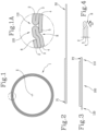
- Figure 1 shows a cross section of a first embodiment of a tube according to this invention, denoted by the reference numeral 1.
- the tube 1 has an internally hollow, cylindrical shape which extends around a longitudinal axis "X" and whose cross section transverse to the longitudinal axis "X" has a three-layer thickness defined by three superposed layers, specifically an outside layer 2, an intermediate layer 3 and an inside layer 4.
- the superposed layers 2, 3, 4 extend along paths which are concentric to each other.
- the tube 1 is obtained by winding a flat, three-layer material 100 ( Figure 3 ) around the longitudinal axis "X" until juxtaposing and coupling to each other opposite lateral edges 110, 120 of the flat multilayer material 100.
- the flat, three-layer material 100 is in turn obtained by folding a single sheet or web 50 about a first fold line "P1" and a second fold line "P2", which are parallel to each other and to the longitudinal axis "X”, in such a way as to mutually superpose corresponding longitudinal areas of the sheet or web 50 to define the three-layer material.
- the inner and outer layers 2, 4 correspond to longitudinal outside areas of the sheet or web 50
- the intermediate layer 3 corresponds to a longitudinal, central area of the sheet or web 50.
- the multilayer material 100 is obtained by folding the sheet or web 50 about the two fold lines "P1 ", "P2" in such a way that the layers 2, 3, 4 follow each other along an S-shaped path.
- the initial sheet or web 50 preferably has a single layer configuration and is made, for example, of paper material.
- the layers 2, 3, 4 of the three-layer material 100 are disposed in such a way that mutually adjacent layers are joined together along a respective folding zone extending parallel to the longitudinal axis "X" and integral with the adjacent layers in such a way that each layer constitutes an extension of at least one adjacent layer.
- the end edges 110, 120 each have a respective folding zone between two adjacent layers 2, 3; 3, 4.
- One of the layers specifically the inside layer 4 has, along a first lateral edge 110 of the multilayer web 100, a lateral border 5 protruding from the intermediate layer 3 to define an element for joining the opposite lateral edges 110, 120 of the multilayer material 100 so as to circumferentially close the tube 1.
- the protruding border 5 has a single layer configuration and is defined by an extension of only one of the layers, specifically the inside layer 4 (or alternatively, in an equivalent embodiment not illustrated, the outside layer).
- the opposite layer (specifically, the outside layer 2 in the configuration of Figures 1-4 ) is smaller in width than the intermediate layer 3 to define a retracted lateral edge 6 behind a folding and splicing zone between the other two layers 3, 4 (that is to say, behind the corresponding lateral edge 120).
- the aforesaid folding and splicing zone associated with the retracted edge 6 adopts a deformed, double notch configuration ( Figures 1A-4 ) to define, on the inside, a recessed zone "R" designed to receive the protruding lateral border 5 of the inside layer 4 and, on the outside, a relief feature designed to be substantially aligned with the retracted edge 6 of the outside layer 2.
- Figures 5-8 show a second embodiment of the tube 1 according to the invention.
- This embodiment differs from the embodiment of Figures 1-4 in that the multilayer material 100 is obtained by folding a single sheet or web 50 about the two fold lines "P1", "P2" in such a way that the layers 2, 3, 4 follow each other along a spiral path.
- the outer layers 2, 4 correspond to a first longitudinal outer area and to a longitudinal, central area of the sheet or web 50, respectively, whilst the intermediate layer 3 corresponds to a second longitudinal outer area of the sheet or web 50.
- the intermediate layer 3 is smaller in width than the outer layers 2, 4 so that the free inner edge 7 of the central layer is spaced from the fold line "P2" between the outer layers 2, 4 (that is to say, from the corresponding lateral edge 120 of the three-layer material 100) to allow making a recessed zone "R" of a first of the outer layers 2, 4, where the latter has, on the side opposite to the recessed zone "R” a protruding lateral border 5 intended to be coupled to the recessed zone "R” to define an element for joining the opposite lateral edges 110, 120 of the multilayer material 100 so as to circumferentially close the tube 1.
- the retracted edge 7 thanks to its distance from the respective folding zone, defines a cavity 8 which is interposed between the two outer layers 2, 4.
- the cavity 8 defines a flattening zone where one of the two outer layers 2, 4 is deformed to create the recessed zone "R".
- the recessed zone "R" and the protruding lateral border 5 are defined on the outside layer 2 of the tube 1. Under the protruding lateral border 5, the two folding zones of the other two layers 3, 4 are disposed close together or in abutment to enable closing the tube 1.
- FIG. 9-12 differs from the embodiment of figures 5-8 in that the recessed zone "R" and the protruding lateral border 5 are defined on the inside layer 4 of the tube 1.
- the two folding zones of the other two layers 2, 3 are disposed close together or in abutment to enable closing the tube 1.
- the layers 2, 3, 4 are connected to each other by adhesive, preferably by an uninterrupted intermediate layer of adhesive or, alternatively, according to a specific, predetermined pattern.
- the adhesive may be the same adhesive as that used to fix the protruding lateral border 5 or it may be a different type of adhesive.
- Figure 13 shows a schematic view of a portion of a machine used for making the tube 1 and, specifically, for making the three-layer material 100.
- the machine initially comprises a scoring tool 200 defined in particular by a pair of opposed rollers, at least one of which is provided with a pair of discs or ridges 210 which are axially spaced from each other to make corresponding parallel lines of weakness "L1", "L2" on the initial web 50.
- the number of discs or ridges 210 depends on the number of lines of weakness to be made and hence on the number of layers of the multilayer material to be obtained and may therefore be different from two, as in the embodiments shown in the accompanying drawings.
- the machine Downstream of the scoring tool 200, the machine comprises two laminating or folding elements 300, 400, each of which is intended to fold the web 50 along a corresponding fold line coinciding with one of the aforementioned lines of weakness "L1", "L2".
- the two folding elements 300, 400 are disposed one after the other to make successive folds on the web 50.
- each folding element 300, 400 has a rigid structure comprising a thin plate lying in a plane parallel to the web 50 so as to be interposed between two adjacent layers being formed.
- each folding element 300, 400 has a shelf-like structure, supported on one side and having a suspended portion defining a respective folding edge 310, 410 intended to be exactly superposed on the respective fold line to define a laminator for folding the web 50.
- each folding element 300, 400 may be associated with a corresponding fixed diverter for progressively flattening a longitudinal area of the web 50 over an adjacent longitudinal area while folding the web 50 around the fold lines.
- the position and structure of the scoring tool 200 is determined in such a way as to make the lines of weakness "L1", “L2" (hence the fold lines) at the desired position, specifically in such a way as to make both the protruding lateral border of one of the two outer layers and the retracted edge of the inner layer.
- the present invention achieves the preset aims, overcoming the disadvantages of the prior art.
- making all the lines of weakness on the web using a single scoring tool allows planning the lines of weakness in advance according to an extremely precise predetermined geometry repeatable over time.
Landscapes
- Making Paper Articles (AREA)
- Laminated Bodies (AREA)
Claims (23)
- Mehrschichtiges Rohr der tabakverarbeitenden Industrie, das eine innenseitig hohle zylindrische Form aufweist, sich erstreckend rund um eine Längsachse (X), und dessen Querschnitt quer zur Längsachse (X) eine mehrschichtige Dicke aufweist, die durch mindestens drei übereinandergelagerte Schichten (2, 3, 4) definiert ist, dadurch gekennzeichnet, dass es erhalten wird, indem ein flaches mehrschichtiges Material (100) rund um die Längsachse gewickelt wird, bis entgegengesetzte seitliche Kanten (110, 120) des flachen mehrschichtigen Materials (100) nebeneinander angeordnet und miteinander gekuppelt sind, wobei das flache mehrschichtige Material (100) durch Falten einer einzigen Folie oder Bahn (50) um mindestens zwei Faltlinien (P1, P2) erhalten wird, die parallel zur Längsachse (X) verlaufen, um entsprechende Längszonen der Folie oder Bahn (50) übereinanderzulagern und die mehrschichtige Dicke zu definieren.
- Rohr nach Anspruch 1, wobei sich die übereinandergelagerten Schichten (2, 3, 4) entlang konzentrischer Wege erstrecken und wobei gegenseitig angrenzende Schichten (2, 3, 4) der mehrschichtigen Dicke entlang einer Faltzone zusammengefügt sind, die sich parallel zur Längsachse (X) erstreckt und in einem Stück mit den angrenzenden Schichten (2, 3, 4) ausgebildet ist, sodass eine jede Schicht (2, 3, 4) eine Ausdehnung von mindestens einer angrenzenden Schicht (2, 3, 4) darstellt.
- Rohr nach Anspruch 2, wobei die konzentrischen Wege durch jeweilige zylindrische Oberflächen einer jeden Schicht (2, 3, 4) definiert sind, wobei das Rohr insbesondere durch Wickeln des flachen mehrschichtigen Materials (100) rund um die Längsachse (X) erhalten wird, sodass das Nebeneinanderanordnen und Koppeln der entgegengesetzten seitlichen Kanten (110, 120) des flachen mehrschichtigen Materials (100) bewirkt, dass eine jede Schicht (2, 3, 4) auf einer jeweiligen geschlossenen zylindrischen Positionierungsoberfläche liegt, wobei die zylindrische Positionierungsoberflächen der Schicht (2, 3, 4) konzentrisch um die Längsachse (X) angeordnet sind.
- Rohr nach einem der vorhergehenden Ansprüche, wobei die Folie oder die Bahn (50) eine einschichtige Auslegung aufweist und vorzugsweise aus Papiermaterial besteht.
- Rohr nach einem der vorhergehenden Ansprüche, wobei eine der Schichten (2, 3, 4) entlang einer ersten seitlichen Kante (110, 120) der mehrschichtigen Bahn (100) einen seitlichen Rand (5) aufweist, der aus einer angrenzenden Schicht (2, 3, 4) hervorsteht, wobei der hervorstehende seitliche Rand (5) ein Element zum Zusammenfügen der entgegengesetzten seitlichen Kanten (110, 120) des mehrschichtigen Materials (100) definiert, sodass das Rohr (1) umfangseitig geschlossen ist.
- Rohr nach Anspruch 5, wobei die mehrschichtige Bahn (100) auf ihrer zweiten seitlichen Kante (110, 120), die gegenständig zur ersten seitlichen Kante (110, 120) und dieser zugewandt angeordnet ist, mit einer Ausnehmung versehen ist, die passend zum hervorstehenden seitlichen Rand (5) ausgebildet ist, sodass der hervorstehende seitliche Rand (5) in der Ausnehmung positioniert ist und dem Rohr eine glatte, knickfreie kreisförmige Auslegung an der Zone, an der die seitlichen Kanten (110, 120) verspleißt sind, verleiht.
- Rohr nach Anspruch 5 oder 6, wobei der hervorstehende seitliche Rand (5), der das Zusammenfügungselement definiert, eine einschichtige Auslegung aufweist und durch eine Ausdehnung von nur einer der Schichten (2, 3, 4) definiert ist.
- Rohr nach einem der vorhergehenden Ansprüche, wobei das mehrschichtige Material (100) erhalten wird, indem eine einzelne Folie oder Bahn (50) um die parallelen Faltlinien (P1, P2) gefaltet wird, sodass die Schichten (2, 3, 4) entlang eines S-förmigen Wegs aufeinanderfolgen, wobei die äußeren Schichten (2, 4) den äußeren Längsbereichen der Folie oder Bahn (50) entsprechen, während mindestens eine Zwischenschicht (3) einem zentralen Längsbereich der Folie oder Bahn (50) entspricht.
- Rohr nach Anspruch 8, wobei eine erste der äußeren Schichten (2, 4) breiter ist als die Zwischenschicht (3), um einen hervorstehenden seitlichen Rand (5) zu definieren, der ein Element definiert, um die entgegengesetzten seitlichen Kanten (110, 120) des mehrschichtigen Materials (100) zusammenzufügen, sodass das Rohr (1) umfangseitig geschlossen ist.
- Rohr nach Anspruch 9, wobei die zweite äußere Schicht (2, 4) schmäler ist als die Zwischenschicht (3) und eine eingezogene Kante (6) hinter einer Falt- und Spleißzone zwischen den anderen beiden Schichten (2, 3, 4) definiert, und wobei die Falt- und Spleißzone im Rohr (1) eine verformte Doppelkerbenauslegung einnimmt, um auf einer Seite eine vertiefte Zone (R) zu definieren, die ausgestaltet ist, um den hervorstehenden seitlichen Rand (5) der ersten äußeren Schicht (2, 4) aufzunehmen, und auf der anderen Seite ein erhabenes Teil, das ausgestaltet ist, um im Wesentlichen fluchtend zur eingezogenen Kante (6) der zweiten äußeren Schicht (2, 4) angeordnet zu sein.
- Rohr nach einem der Ansprüche 1 bis 7, wobei das mehrschichtige Material (100) erhalten wird, indem eine einzelne Folie oder Bahn (50) um die parallelen Faltlinien (P1, P2) gefaltet wird, sodass die Schichten (2, 3, 4) entlang eines spiralförmigen Wegs aufeinanderfolgen, wobei die äußeren Schichten (2, 4) jeweils einem ersten äußeren Längsbereich und einem zentralen Längsbereich der Folie oder Bahn (50) entsprechen, während mindestens eine Zwischenschicht (3) einem zweiten äußeren Längsbereich der Folie oder Bahn (50) entspricht.
- Rohr nach Anspruch 11, wobei die mindestens eine Zwischenschicht (3) schmäler ist als die äußeren Schichten (2, 4), sodass die freie innere Kante (7) der Zwischenschicht (3) von der Faltlinie zwischen den äußeren Schichten (2, 4) beabstandet ist, um eine vertiefte Zone (R) einer ersten der äußeren Schichten (2, 4) zu definieren, wobei die erste äußere Schicht (2, 4) auf der der vertieften Zone (R) entgegengesetzten Seite einen hervorstehenden seitlichen Rand (5) aufweist, der mit der vertieften Zone (R) der ersten Schicht (2, 4) gekoppelt ist, um ein Element zum Zusammenfügen der entgegengesetzten seitlichen Kanten (110, 120) des mehrschichtigen Materials (100) zu definieren, sodass das Rohr (1) umfangseitig geschlossen ist.
- Rohr nach einem der vorhergehenden Ansprüche, wobei die übereinandergelagerten Schichten (2, 3, 4) miteinander durch Klebstoff verbunden sind, vorzugsweise durch mindestens eine ununterbrochene Zwischenschicht aus Klebstoff und noch bevorzugter durch eine Zwischenschicht aus Klebstoff für ein jedes Paar angrenzender Schichten (2, 3, 4).
- Verfahren zur Herstellung eines mehrschichtigen Rohrs der tabakverarbeitenden Industrie, umfassend die folgenden Schritte:- Zuführen einer durchgehenden Bahn (50) entlang einer Zuführungsrichtung;- Falten der durchgehenden Bahn (50) um sich selbst um mindestens eine erste Längsfaltlinie (P1, P2) parallel zur Zuführungsrichtung, während die durchgehende Bahn (50) zugeführt wird, bis eine mehrschichtige Bahn (100) erhalten wird, die durch Übereinanderlagern von mindestens einem ersten Längsbereich und einem zweiten Längsbereich der durchgehenden Bahn (50) definiert ist;- Wickeln der mehrschichtigen Bahn (100) rund um eine Längsachse (X) parallel zur Zuführungsrichtung, bis entgegengesetzte seitliche Kanten (110, 120) der mehrschichtigen Bahn (100) nebeneinander angeordnet sind;- stabiles Verbinden der entgegengesetzten seitlichen Kanten (110, 120) der mehrschichtigen Bahn (100) miteinander,dadurch gekennzeichnet, dass der Schritt zum Falten der durchgehenden Bahn (50) durchgeführt wird, indem die Bahn (50) ein erstes Mal um eine erste Längsfaltlinie (P1) gefaltet wird und die Bahn (50) dann erneut um eine zweite Längsfaltlinie (P2) gefaltet wird, sodass eine mindestens dreischichtige Bahn (100) erhalten wird, wobei die Faltlinien (P1, P2) parallel zueinander und parallel zur Zuführungsrichtung der durchgehenden Bahn angeordnet sind.
- Verfahren nach Anspruch 14, wobei der Schritt zum Falten durchgeführt wird, indem die Bahn (50) rund um mindestens ein Faltelement (300, 400) gefaltet wird, bei dem es sich vorzugsweise um eine dünne Längsplatte handelt, sodass die mindestens eine Faltlinie (P1, P2) an einer jeweiligen Längskante (310, 410) des mindestens einen Faltelements (300, 400) platziert ist.
- Verfahren nach Anspruch 14 oder 15, wobei vor dem Schritt zum Falten ein Schritt zum Herstellen von mindestens einer Längsschwächungslinie (L1, L2) erfolgt, um mit einer jeweiligen Längsfaltlinie (P1, P2) während des Schritts zum Falten übereinzustimmen.
- Verfahren nach Anspruch 16, wobei der Schritt zum Falten der durchgehenden Bahn (50) durch Falten der Bahn (50) um sich selbst um mindestens zwei parallele Längsfaltlinien (P1, P2) erfolgt, um mindestens eine dreischichtige Bahn (100) zu definieren, wobei der Schritt zum Herstellen von mindestens einer Längsschwächungslinie (L1, L2) durchgeführt wird, indem mindestens zwei Längsschwächungslinien (L1, L2) unter Nutzung eines einzelnen Rillwerkzeugs (200), insbesondere einer Rillwalze, ausgebildet werden, aufweisend mindestens zwei Scheiben oder Rippen (210), die axial voneinander beabstandet sind, um entsprechende parallele Schwächungslinien (L1, L2) auf der Bahn (50) auszubilden.
- Verfahren nach Anspruch 17, wobei der Schritt zum Falten der Bahn (50) durchgeführt wird, indem die Bahn (50) um mindestens zwei Faltlinien (P1, P2) gefaltet wird, sodass ein zentraler Bereich der Bahn (50), der zwischen den beiden Faltlinien (P1, P2) liegt, eine Zwischenschicht (3) der dreischichtigen Bahn (100) definiert, während die verbleibenden Längsbereiche der Bahn (50), die sich auf den äußeren Seiten der beiden Faltlinien (P1, P2) befinden, die äußeren Schichten (2, 4) der mindestens dreischichtigen Bahn (100) definieren, und wobei die Schichten (2, 3, 4) der mindestens dreischichtigen Bahn (100) jeweils entlang eines S-förmigen Wegs aufeinanderfolgen.
- Verfahren nach Anspruch 18, wobei eine erste der äußeren Schichten (2, 4) der mindestens dreischichtigen Bahn (100) breiter ist als die Zwischenschicht (3), um einen hervorstehenden seitlichen Rand (5) zu definieren, definierend ein Element zum Zusammenfügen der entgegengesetzten seitlichen Kanten (110, 120) der mindestens dreischichtigen Bahn (100), sodass das Rohr (1) umfangseitig geschlossen ist.
- Verfahren nach Anspruch 19, wobei die zweite äußere Schicht (2, 4) schmäler ist als die Zwischenschicht (3) und eine eingezogene Kante (6) hinter einer Falt- und Spleißzone zwischen den anderen beiden Schichten (2, 3, 4) definiert, und wobei der Schritt zum Wickeln der mehrschichtigen Bahn (100) rund um die Achse (X) einen Schritt zum Verformen der Falt- und Spleißzone einschließt, sodass eine verformte Doppelkerbenauslegung erhalten wird, um auf einer Seite eine vertiefte Zone (R) zu definieren, die ausgestaltet ist, um den hervorstehenden seitlichen Rand (5) der ersten äußeren Schicht (2, 4) aufzunehmen, und auf der anderen Seite ein erhabenes Teil, das ausgestaltet ist, um fluchtend zur eingezogenen Kante (6) der zweiten äußeren Schicht (2, 4) angeordnet zu sein.
- Verfahren nach Anspruch 17, wobei der Schritt zum Falten der Bahn (50) durchgeführt wird, indem die Bahn (50) um die Faltlinien (P1, P2) gefaltet wird, sodass die äußeren Schichten (2, 4) der mindestens dreischichtigen Bahn (100) jeweils einem ersten äußeren Längsbereich und einem zentralen Längsbereich der Bahn (50) entsprechen, während die mindestens eine Zwischenschicht (3) einem zweiten äußeren Längsbereich der Bahn (50) entspricht, und wobei die Schichten (2, 3, 4) der mindestens dreischichtigen Bahn (100) entlang eines spiralförmigen Wegs aufeinanderfolgen.
- Verfahren nach Anspruch 21, wobei die mindestens eine Zwischenschicht (3) schmäler ist als die äußeren Schichten (2, 4), sodass die freie innere Kante (7) der Zwischenschicht (3) von der Falt- und Spleißlinie zwischen den äußeren Schichten (2, 4) beabstandet ist, um einen Hohlraum (8) zu definieren, und wobei der Schritt zum Wickeln der mehrschichtigen Bahn (100) rund um die Achse (X) einen Schritt zum Verformen der mindestens dreischichtigen Bahn (100) am Hohlraum (8) durch Abflachen einschließt, um eine vertiefte Zone (R) zu erhalten, wobei die erste äußere Schicht (2, 4) auf der der vertieften Zone (R) entgegengesetzten Seite einen vorstehenden seitlichen Rand (5) aufweist, der mit der vertieften Zone (R) gekoppelt ist, um ein Element zum Zusammenfügen der entgegengesetzten seitlichen Kanten (110, 120) des mindestens dreischichtigen Materials (100) zu definieren, sodass das Rohr (1) umfangseitig geschlossen ist.
- Verfahren nach einem der Ansprüche 14 bis 22, wobei der Schritt zum Falten der durchgehenden Bahn (50) um sich selbst um mindestens eine erste Längsfaltlinie (P1, P2) mit einem Schritt zum Auftragen von Klebstoff zwischen angrenzenden Schichten (2, 3, 4) der mehrschichtigen Bahn (100) assoziiert ist, wobei es sich vorzugsweise um mindestens eine ununterbrochene Zwischenschicht aus Klebstoff und noch bevorzugter eine Schicht aus Klebstoff für ein jedes Paar angrenzender Schichten (2, 3, 4) handelt.
Applications Claiming Priority (2)
| Application Number | Priority Date | Filing Date | Title |
|---|---|---|---|
| IT102018000004715A IT201800004715A1 (it) | 2018-04-24 | 2018-04-24 | Tubolare multistrato dell’industria del tabacco e metodo per la realizzazione di detto tubolare multistrato |
| PCT/IB2019/053326 WO2019207471A1 (en) | 2018-04-24 | 2019-04-23 | Multilayer tube of the tobacco industry and method for making the multilayer tube |
Publications (2)
| Publication Number | Publication Date |
|---|---|
| EP3784066A1 EP3784066A1 (de) | 2021-03-03 |
| EP3784066B1 true EP3784066B1 (de) | 2023-07-05 |
Family
ID=62875236
Family Applications (1)
| Application Number | Title | Priority Date | Filing Date |
|---|---|---|---|
| EP19726750.3A Active EP3784066B1 (de) | 2018-04-24 | 2019-04-23 | Mehrschichtiges rohr der tabakverarbeitenden industrie und verfahren zur herstellung des mehrschichtigen rohres |
Country Status (4)
| Country | Link |
|---|---|
| EP (1) | EP3784066B1 (de) |
| IT (1) | IT201800004715A1 (de) |
| PL (1) | PL3784066T3 (de) |
| WO (1) | WO2019207471A1 (de) |
Families Citing this family (3)
| Publication number | Priority date | Publication date | Assignee | Title |
|---|---|---|---|---|
| IT202000003943A1 (it) * | 2020-02-26 | 2021-08-26 | Gd Spa | Macchina e metodo per la realizzazione di un tubolare continuo da materiale in nastro |
| DE102020134003A1 (de) * | 2020-12-17 | 2022-06-23 | Hauni Maschinenbau Gmbh | Vorrichtung und Verfahren zur Herstellung eines stab- oder rohrförmigen Artikels |
| IT202300009255A1 (it) | 2023-05-09 | 2024-11-09 | Gd Spa | Metodo e macchina per la formazione di tubolari multistrato |
Family Cites Families (4)
| Publication number | Priority date | Publication date | Assignee | Title |
|---|---|---|---|---|
| DE2505788C2 (de) * | 1975-02-12 | 1985-03-28 | Hauni-Werke Körber & Co KG, 2050 Hamburg | Verfahren und Maschine zum Herstellen eines mehrwandigen Papierrohres für Rauchartikel-Mundstückhülsen |
| DE2542041A1 (de) * | 1975-09-20 | 1977-03-24 | Hauni Werke Koerber & Co Kg | Verfahren und vorrichtung zum herstellen eines papierrohres fuer rauchartikel-mundstueckhuelsen |
| ITBO20120212A1 (it) * | 2012-04-17 | 2013-10-18 | Emmeci Spa | Sbozzato per la realizzazione di scatole tonde |
| DE102014226019A1 (de) * | 2014-12-16 | 2016-06-16 | Hauni Maschinenbau Ag | Doppellagiges Röhrchen der Tabak verarbeitenden Industrie sowie Vorrichtung und Verfahren zur Herstellung eines derartigen Röhrchens |
-
2018
- 2018-04-24 IT IT102018000004715A patent/IT201800004715A1/it unknown
-
2019
- 2019-04-23 EP EP19726750.3A patent/EP3784066B1/de active Active
- 2019-04-23 PL PL19726750.3T patent/PL3784066T3/pl unknown
- 2019-04-23 WO PCT/IB2019/053326 patent/WO2019207471A1/en not_active Ceased
Also Published As
| Publication number | Publication date |
|---|---|
| EP3784066A1 (de) | 2021-03-03 |
| WO2019207471A1 (en) | 2019-10-31 |
| PL3784066T3 (pl) | 2023-10-23 |
| IT201800004715A1 (it) | 2019-10-24 |
Similar Documents
| Publication | Publication Date | Title |
|---|---|---|
| RU2746381C2 (ru) | Двухслойная трубочка перерабатывающей табак промышленности, а также способ изготовления подобной трубочки | |
| EP3784066B1 (de) | Mehrschichtiges rohr der tabakverarbeitenden industrie und verfahren zur herstellung des mehrschichtigen rohres | |
| EP3636424B1 (de) | Verfahren und vorrichtung zum herstellen von mehrlagigen hülsen für produkte der tabakindustrie | |
| CN108371342B (zh) | 用于制造烟草加工业的条的方法以及条成形装置 | |
| EP0681963B1 (de) | Unterteilung für faltbare Pappschachteln und Verfahren zur Herstellung dieser Unterteilung | |
| EP3033952B1 (de) | Doppellagiges röhrchen der tabak verarbeitenden industrie sowie vorrichtung und verfahren zur herstellung eines derartigen röhrchens | |
| EP3407742B1 (de) | Verfahren und maschine zur herstellung von teilen eines mehrschichtigen, zylindrischen rohrförmigen stabes zur herstellung von im wesentlichen zylindrischen raucher artikeln und anhand des verfahrens und der maschine hergestellte teile | |
| EP3142951B1 (de) | Vorrichtung und verfahren zum spleissen | |
| US3732790A (en) | Corrugated container and method and apparatus for manufacturing the same | |
| JPH08500067A (ja) | 連続的なチューブ状箱体、特にボール箱用の連続チューブ状箱体を製造する方法 | |
| CN108685162B (zh) | 用于制造烟草加工业的至少双层管状的条的方法及用于制造烟草加工业的至少双层条的装置 | |
| CA2448797C (en) | Tube made out of pre-adhered plies | |
| US3280709A (en) | Container and manufacture thereof | |
| EP1574466B1 (de) | Stapelbarer Wickelkern und Verfahren zu seiner Herstellung | |
| EP3636082A2 (de) | Mehrlagige hülse sowie vorrichtung und verfahren zu deren herstellung | |
| JPH0629106B2 (ja) | ウエブの接合方法及び装置 | |
| JP6434962B2 (ja) | 喫煙者商品を生産するための装置 | |
| JP7842781B2 (ja) | 溶接部が印刷内に隠されたパッケージおよび製造方法 | |
| WO2013156912A1 (en) | Blank for making round boxes | |
| JP2005104046A (ja) | 二つ折り書類およびその製本方法 | |
| IT202300009255A1 (it) | Metodo e macchina per la formazione di tubolari multistrato |
Legal Events
| Date | Code | Title | Description |
|---|---|---|---|
| STAA | Information on the status of an ep patent application or granted ep patent |
Free format text: STATUS: THE INTERNATIONAL PUBLICATION HAS BEEN MADE |
|
| PUAI | Public reference made under article 153(3) epc to a published international application that has entered the european phase |
Free format text: ORIGINAL CODE: 0009012 |
|
| STAA | Information on the status of an ep patent application or granted ep patent |
Free format text: STATUS: REQUEST FOR EXAMINATION WAS MADE |
|
| 17P | Request for examination filed |
Effective date: 20201007 |
|
| AK | Designated contracting states |
Kind code of ref document: A1 Designated state(s): AL AT BE BG CH CY CZ DE DK EE ES FI FR GB GR HR HU IE IS IT LI LT LU LV MC MK MT NL NO PL PT RO RS SE SI SK SM TR |
|
| AX | Request for extension of the european patent |
Extension state: BA ME |
|
| DAV | Request for validation of the european patent (deleted) | ||
| DAX | Request for extension of the european patent (deleted) | ||
| GRAP | Despatch of communication of intention to grant a patent |
Free format text: ORIGINAL CODE: EPIDOSNIGR1 |
|
| STAA | Information on the status of an ep patent application or granted ep patent |
Free format text: STATUS: GRANT OF PATENT IS INTENDED |
|
| INTG | Intention to grant announced |
Effective date: 20230307 |
|
| GRAS | Grant fee paid |
Free format text: ORIGINAL CODE: EPIDOSNIGR3 |
|
| GRAA | (expected) grant |
Free format text: ORIGINAL CODE: 0009210 |
|
| STAA | Information on the status of an ep patent application or granted ep patent |
Free format text: STATUS: THE PATENT HAS BEEN GRANTED |
|
| AK | Designated contracting states |
Kind code of ref document: B1 Designated state(s): AL AT BE BG CH CY CZ DE DK EE ES FI FR GB GR HR HU IE IS IT LI LT LU LV MC MK MT NL NO PL PT RO RS SE SI SK SM TR |
|
| P01 | Opt-out of the competence of the unified patent court (upc) registered |
Effective date: 20230527 |
|
| REG | Reference to a national code |
Ref country code: CH Ref legal event code: EP |
|
| REG | Reference to a national code |
Ref country code: AT Ref legal event code: REF Ref document number: 1583963 Country of ref document: AT Kind code of ref document: T Effective date: 20230715 |
|
| REG | Reference to a national code |
Ref country code: DE Ref legal event code: R096 Ref document number: 602019032137 Country of ref document: DE |
|
| REG | Reference to a national code |
Ref country code: IE Ref legal event code: FG4D |
|
| REG | Reference to a national code |
Ref country code: NL Ref legal event code: FP |
|
| REG | Reference to a national code |
Ref country code: LT Ref legal event code: MG9D |
|
| REG | Reference to a national code |
Ref country code: AT Ref legal event code: MK05 Ref document number: 1583963 Country of ref document: AT Kind code of ref document: T Effective date: 20230705 |
|
| PG25 | Lapsed in a contracting state [announced via postgrant information from national office to epo] |
Ref country code: GR Free format text: LAPSE BECAUSE OF FAILURE TO SUBMIT A TRANSLATION OF THE DESCRIPTION OR TO PAY THE FEE WITHIN THE PRESCRIBED TIME-LIMIT Effective date: 20231006 |
|
| PG25 | Lapsed in a contracting state [announced via postgrant information from national office to epo] |
Ref country code: ES Free format text: LAPSE BECAUSE OF FAILURE TO SUBMIT A TRANSLATION OF THE DESCRIPTION OR TO PAY THE FEE WITHIN THE PRESCRIBED TIME-LIMIT Effective date: 20230705 |
|
| PG25 | Lapsed in a contracting state [announced via postgrant information from national office to epo] |
Ref country code: IS Free format text: LAPSE BECAUSE OF FAILURE TO SUBMIT A TRANSLATION OF THE DESCRIPTION OR TO PAY THE FEE WITHIN THE PRESCRIBED TIME-LIMIT Effective date: 20231105 |
|
| PG25 | Lapsed in a contracting state [announced via postgrant information from national office to epo] |
Ref country code: SE Free format text: LAPSE BECAUSE OF FAILURE TO SUBMIT A TRANSLATION OF THE DESCRIPTION OR TO PAY THE FEE WITHIN THE PRESCRIBED TIME-LIMIT Effective date: 20230705 Ref country code: RS Free format text: LAPSE BECAUSE OF FAILURE TO SUBMIT A TRANSLATION OF THE DESCRIPTION OR TO PAY THE FEE WITHIN THE PRESCRIBED TIME-LIMIT Effective date: 20230705 Ref country code: PT Free format text: LAPSE BECAUSE OF FAILURE TO SUBMIT A TRANSLATION OF THE DESCRIPTION OR TO PAY THE FEE WITHIN THE PRESCRIBED TIME-LIMIT Effective date: 20231106 Ref country code: NO Free format text: LAPSE BECAUSE OF FAILURE TO SUBMIT A TRANSLATION OF THE DESCRIPTION OR TO PAY THE FEE WITHIN THE PRESCRIBED TIME-LIMIT Effective date: 20231005 Ref country code: LV Free format text: LAPSE BECAUSE OF FAILURE TO SUBMIT A TRANSLATION OF THE DESCRIPTION OR TO PAY THE FEE WITHIN THE PRESCRIBED TIME-LIMIT Effective date: 20230705 Ref country code: LT Free format text: LAPSE BECAUSE OF FAILURE TO SUBMIT A TRANSLATION OF THE DESCRIPTION OR TO PAY THE FEE WITHIN THE PRESCRIBED TIME-LIMIT Effective date: 20230705 Ref country code: IS Free format text: LAPSE BECAUSE OF FAILURE TO SUBMIT A TRANSLATION OF THE DESCRIPTION OR TO PAY THE FEE WITHIN THE PRESCRIBED TIME-LIMIT Effective date: 20231105 Ref country code: HR Free format text: LAPSE BECAUSE OF FAILURE TO SUBMIT A TRANSLATION OF THE DESCRIPTION OR TO PAY THE FEE WITHIN THE PRESCRIBED TIME-LIMIT Effective date: 20230705 Ref country code: GR Free format text: LAPSE BECAUSE OF FAILURE TO SUBMIT A TRANSLATION OF THE DESCRIPTION OR TO PAY THE FEE WITHIN THE PRESCRIBED TIME-LIMIT Effective date: 20231006 Ref country code: FI Free format text: LAPSE BECAUSE OF FAILURE TO SUBMIT A TRANSLATION OF THE DESCRIPTION OR TO PAY THE FEE WITHIN THE PRESCRIBED TIME-LIMIT Effective date: 20230705 Ref country code: ES Free format text: LAPSE BECAUSE OF FAILURE TO SUBMIT A TRANSLATION OF THE DESCRIPTION OR TO PAY THE FEE WITHIN THE PRESCRIBED TIME-LIMIT Effective date: 20230705 Ref country code: AT Free format text: LAPSE BECAUSE OF FAILURE TO SUBMIT A TRANSLATION OF THE DESCRIPTION OR TO PAY THE FEE WITHIN THE PRESCRIBED TIME-LIMIT Effective date: 20230705 |
|
| REG | Reference to a national code |
Ref country code: DE Ref legal event code: R097 Ref document number: 602019032137 Country of ref document: DE |
|
| PG25 | Lapsed in a contracting state [announced via postgrant information from national office to epo] |
Ref country code: SM Free format text: LAPSE BECAUSE OF FAILURE TO SUBMIT A TRANSLATION OF THE DESCRIPTION OR TO PAY THE FEE WITHIN THE PRESCRIBED TIME-LIMIT Effective date: 20230705 Ref country code: RO Free format text: LAPSE BECAUSE OF FAILURE TO SUBMIT A TRANSLATION OF THE DESCRIPTION OR TO PAY THE FEE WITHIN THE PRESCRIBED TIME-LIMIT Effective date: 20230705 Ref country code: EE Free format text: LAPSE BECAUSE OF FAILURE TO SUBMIT A TRANSLATION OF THE DESCRIPTION OR TO PAY THE FEE WITHIN THE PRESCRIBED TIME-LIMIT Effective date: 20230705 Ref country code: DK Free format text: LAPSE BECAUSE OF FAILURE TO SUBMIT A TRANSLATION OF THE DESCRIPTION OR TO PAY THE FEE WITHIN THE PRESCRIBED TIME-LIMIT Effective date: 20230705 Ref country code: CZ Free format text: LAPSE BECAUSE OF FAILURE TO SUBMIT A TRANSLATION OF THE DESCRIPTION OR TO PAY THE FEE WITHIN THE PRESCRIBED TIME-LIMIT Effective date: 20230705 Ref country code: SK Free format text: LAPSE BECAUSE OF FAILURE TO SUBMIT A TRANSLATION OF THE DESCRIPTION OR TO PAY THE FEE WITHIN THE PRESCRIBED TIME-LIMIT Effective date: 20230705 |
|
| PLBE | No opposition filed within time limit |
Free format text: ORIGINAL CODE: 0009261 |
|
| STAA | Information on the status of an ep patent application or granted ep patent |
Free format text: STATUS: NO OPPOSITION FILED WITHIN TIME LIMIT |
|
| PG25 | Lapsed in a contracting state [announced via postgrant information from national office to epo] |
Ref country code: IT Free format text: LAPSE BECAUSE OF FAILURE TO SUBMIT A TRANSLATION OF THE DESCRIPTION OR TO PAY THE FEE WITHIN THE PRESCRIBED TIME-LIMIT Effective date: 20230705 |
|
| 26N | No opposition filed |
Effective date: 20240408 |
|
| PG25 | Lapsed in a contracting state [announced via postgrant information from national office to epo] |
Ref country code: SI Free format text: LAPSE BECAUSE OF FAILURE TO SUBMIT A TRANSLATION OF THE DESCRIPTION OR TO PAY THE FEE WITHIN THE PRESCRIBED TIME-LIMIT Effective date: 20230705 |
|
| PG25 | Lapsed in a contracting state [announced via postgrant information from national office to epo] |
Ref country code: BG Free format text: LAPSE BECAUSE OF FAILURE TO SUBMIT A TRANSLATION OF THE DESCRIPTION OR TO PAY THE FEE WITHIN THE PRESCRIBED TIME-LIMIT Effective date: 20230705 |
|
| PG25 | Lapsed in a contracting state [announced via postgrant information from national office to epo] |
Ref country code: MC Free format text: LAPSE BECAUSE OF FAILURE TO SUBMIT A TRANSLATION OF THE DESCRIPTION OR TO PAY THE FEE WITHIN THE PRESCRIBED TIME-LIMIT Effective date: 20230705 |
|
| PG25 | Lapsed in a contracting state [announced via postgrant information from national office to epo] |
Ref country code: MC Free format text: LAPSE BECAUSE OF FAILURE TO SUBMIT A TRANSLATION OF THE DESCRIPTION OR TO PAY THE FEE WITHIN THE PRESCRIBED TIME-LIMIT Effective date: 20230705 Ref country code: BG Free format text: LAPSE BECAUSE OF FAILURE TO SUBMIT A TRANSLATION OF THE DESCRIPTION OR TO PAY THE FEE WITHIN THE PRESCRIBED TIME-LIMIT Effective date: 20230705 |
|
| REG | Reference to a national code |
Ref country code: CH Ref legal event code: PL |
|
| PG25 | Lapsed in a contracting state [announced via postgrant information from national office to epo] |
Ref country code: LU Free format text: LAPSE BECAUSE OF NON-PAYMENT OF DUE FEES Effective date: 20240423 |
|
| GBPC | Gb: european patent ceased through non-payment of renewal fee |
Effective date: 20240423 |
|
| REG | Reference to a national code |
Ref country code: BE Ref legal event code: MM Effective date: 20240430 |
|
| PG25 | Lapsed in a contracting state [announced via postgrant information from national office to epo] |
Ref country code: LU Free format text: LAPSE BECAUSE OF NON-PAYMENT OF DUE FEES Effective date: 20240423 |
|
| PG25 | Lapsed in a contracting state [announced via postgrant information from national office to epo] |
Ref country code: BE Free format text: LAPSE BECAUSE OF NON-PAYMENT OF DUE FEES Effective date: 20240430 |
|
| PG25 | Lapsed in a contracting state [announced via postgrant information from national office to epo] |
Ref country code: GB Free format text: LAPSE BECAUSE OF NON-PAYMENT OF DUE FEES Effective date: 20240423 |
|
| PG25 | Lapsed in a contracting state [announced via postgrant information from national office to epo] |
Ref country code: FR Free format text: LAPSE BECAUSE OF NON-PAYMENT OF DUE FEES Effective date: 20240430 |
|
| PG25 | Lapsed in a contracting state [announced via postgrant information from national office to epo] |
Ref country code: GB Free format text: LAPSE BECAUSE OF NON-PAYMENT OF DUE FEES Effective date: 20240423 Ref country code: FR Free format text: LAPSE BECAUSE OF NON-PAYMENT OF DUE FEES Effective date: 20240430 Ref country code: BE Free format text: LAPSE BECAUSE OF NON-PAYMENT OF DUE FEES Effective date: 20240430 Ref country code: CH Free format text: LAPSE BECAUSE OF NON-PAYMENT OF DUE FEES Effective date: 20240430 |
|
| PG25 | Lapsed in a contracting state [announced via postgrant information from national office to epo] |
Ref country code: IE Free format text: LAPSE BECAUSE OF NON-PAYMENT OF DUE FEES Effective date: 20240423 |
|
| PGFP | Annual fee paid to national office [announced via postgrant information from national office to epo] |
Ref country code: NL Payment date: 20250427 Year of fee payment: 7 |
|
| PGFP | Annual fee paid to national office [announced via postgrant information from national office to epo] |
Ref country code: DE Payment date: 20250429 Year of fee payment: 7 Ref country code: PL Payment date: 20250401 Year of fee payment: 7 |
|
| PG25 | Lapsed in a contracting state [announced via postgrant information from national office to epo] |
Ref country code: CY Free format text: LAPSE BECAUSE OF FAILURE TO SUBMIT A TRANSLATION OF THE DESCRIPTION OR TO PAY THE FEE WITHIN THE PRESCRIBED TIME-LIMIT; INVALID AB INITIO Effective date: 20190423 |
|
| PG25 | Lapsed in a contracting state [announced via postgrant information from national office to epo] |
Ref country code: HU Free format text: LAPSE BECAUSE OF FAILURE TO SUBMIT A TRANSLATION OF THE DESCRIPTION OR TO PAY THE FEE WITHIN THE PRESCRIBED TIME-LIMIT; INVALID AB INITIO Effective date: 20190423 |