EP3781828B1 - Générateur à turbines et procédé d'opération d'un générateur à turbine - Google Patents
Générateur à turbines et procédé d'opération d'un générateur à turbine Download PDFInfo
- Publication number
- EP3781828B1 EP3781828B1 EP19719474.9A EP19719474A EP3781828B1 EP 3781828 B1 EP3781828 B1 EP 3781828B1 EP 19719474 A EP19719474 A EP 19719474A EP 3781828 B1 EP3781828 B1 EP 3781828B1
- Authority
- EP
- European Patent Office
- Prior art keywords
- turbine
- generator
- coils
- axial
- bearing
- Prior art date
- Legal status (The legal status is an assumption and is not a legal conclusion. Google has not performed a legal analysis and makes no representation as to the accuracy of the status listed.)
- Active
Links
- 238000000034 method Methods 0.000 title claims description 12
- 238000007789 sealing Methods 0.000 claims description 44
- 230000008859 change Effects 0.000 claims description 18
- 230000000694 effects Effects 0.000 claims description 17
- 230000001105 regulatory effect Effects 0.000 claims description 8
- 230000001276 controlling effect Effects 0.000 claims description 7
- 230000000670 limiting effect Effects 0.000 claims description 2
- 230000008569 process Effects 0.000 description 6
- 238000001816 cooling Methods 0.000 description 5
- 230000002829 reductive effect Effects 0.000 description 5
- 230000033228 biological regulation Effects 0.000 description 3
- 239000002826 coolant Substances 0.000 description 3
- 230000002596 correlated effect Effects 0.000 description 3
- 238000013461 design Methods 0.000 description 3
- 238000005259 measurement Methods 0.000 description 3
- 230000000875 corresponding effect Effects 0.000 description 2
- 238000011161 development Methods 0.000 description 2
- 230000018109 developmental process Effects 0.000 description 2
- 238000012546 transfer Methods 0.000 description 2
- MMOXZBCLCQITDF-UHFFFAOYSA-N N,N-diethyl-m-toluamide Chemical compound CCN(CC)C(=O)C1=CC=CC(C)=C1 MMOXZBCLCQITDF-UHFFFAOYSA-N 0.000 description 1
- 240000001439 Opuntia Species 0.000 description 1
- 235000004727 Opuntia ficus indica Nutrition 0.000 description 1
- 241000307523 Xenostegia media Species 0.000 description 1
- 238000013459 approach Methods 0.000 description 1
- 230000004323 axial length Effects 0.000 description 1
- 238000005452 bending Methods 0.000 description 1
- 230000007423 decrease Effects 0.000 description 1
- 230000003247 decreasing effect Effects 0.000 description 1
- 238000009795 derivation Methods 0.000 description 1
- 238000010586 diagram Methods 0.000 description 1
- 238000006073 displacement reaction Methods 0.000 description 1
- 239000007789 gas Substances 0.000 description 1
- 230000000977 initiatory effect Effects 0.000 description 1
- 238000004519 manufacturing process Methods 0.000 description 1
- 230000036961 partial effect Effects 0.000 description 1
- 230000001681 protective effect Effects 0.000 description 1
- 238000011084 recovery Methods 0.000 description 1
- 230000009467 reduction Effects 0.000 description 1
- 239000003507 refrigerant Substances 0.000 description 1
- 239000013589 supplement Substances 0.000 description 1
- 230000007704 transition Effects 0.000 description 1
- 238000011144 upstream manufacturing Methods 0.000 description 1
- 239000002918 waste heat Substances 0.000 description 1
- 238000004804 winding Methods 0.000 description 1
Images


Classifications
-
- F—MECHANICAL ENGINEERING; LIGHTING; HEATING; WEAPONS; BLASTING
- F01—MACHINES OR ENGINES IN GENERAL; ENGINE PLANTS IN GENERAL; STEAM ENGINES
- F01D—NON-POSITIVE DISPLACEMENT MACHINES OR ENGINES, e.g. STEAM TURBINES
- F01D15/00—Adaptations of machines or engines for special use; Combinations of engines with devices driven thereby
- F01D15/10—Adaptations for driving, or combinations with, electric generators
-
- F—MECHANICAL ENGINEERING; LIGHTING; HEATING; WEAPONS; BLASTING
- F16—ENGINEERING ELEMENTS AND UNITS; GENERAL MEASURES FOR PRODUCING AND MAINTAINING EFFECTIVE FUNCTIONING OF MACHINES OR INSTALLATIONS; THERMAL INSULATION IN GENERAL
- F16C—SHAFTS; FLEXIBLE SHAFTS; ELEMENTS OR CRANKSHAFT MECHANISMS; ROTARY BODIES OTHER THAN GEARING ELEMENTS; BEARINGS
- F16C32/00—Bearings not otherwise provided for
- F16C32/04—Bearings not otherwise provided for using magnetic or electric supporting means
- F16C32/0406—Magnetic bearings
- F16C32/044—Active magnetic bearings
- F16C32/0442—Active magnetic bearings with devices affected by abnormal, undesired or non-standard conditions such as shock-load, power outage, start-up or touchdown
-
- F—MECHANICAL ENGINEERING; LIGHTING; HEATING; WEAPONS; BLASTING
- F01—MACHINES OR ENGINES IN GENERAL; ENGINE PLANTS IN GENERAL; STEAM ENGINES
- F01D—NON-POSITIVE DISPLACEMENT MACHINES OR ENGINES, e.g. STEAM TURBINES
- F01D25/00—Component parts, details, or accessories, not provided for in, or of interest apart from, other groups
- F01D25/16—Arrangement of bearings; Supporting or mounting bearings in casings
-
- F—MECHANICAL ENGINEERING; LIGHTING; HEATING; WEAPONS; BLASTING
- F01—MACHINES OR ENGINES IN GENERAL; ENGINE PLANTS IN GENERAL; STEAM ENGINES
- F01D—NON-POSITIVE DISPLACEMENT MACHINES OR ENGINES, e.g. STEAM TURBINES
- F01D25/00—Component parts, details, or accessories, not provided for in, or of interest apart from, other groups
- F01D25/18—Lubricating arrangements
- F01D25/183—Sealing means
-
- F—MECHANICAL ENGINEERING; LIGHTING; HEATING; WEAPONS; BLASTING
- F02—COMBUSTION ENGINES; HOT-GAS OR COMBUSTION-PRODUCT ENGINE PLANTS
- F02C—GAS-TURBINE PLANTS; AIR INTAKES FOR JET-PROPULSION PLANTS; CONTROLLING FUEL SUPPLY IN AIR-BREATHING JET-PROPULSION PLANTS
- F02C1/00—Gas-turbine plants characterised by the use of hot gases or unheated pressurised gases, as the working fluid
- F02C1/04—Gas-turbine plants characterised by the use of hot gases or unheated pressurised gases, as the working fluid the working fluid being heated indirectly
- F02C1/05—Gas-turbine plants characterised by the use of hot gases or unheated pressurised gases, as the working fluid the working fluid being heated indirectly characterised by the type or source of heat, e.g. using nuclear or solar energy
-
- F—MECHANICAL ENGINEERING; LIGHTING; HEATING; WEAPONS; BLASTING
- F16—ENGINEERING ELEMENTS AND UNITS; GENERAL MEASURES FOR PRODUCING AND MAINTAINING EFFECTIVE FUNCTIONING OF MACHINES OR INSTALLATIONS; THERMAL INSULATION IN GENERAL
- F16C—SHAFTS; FLEXIBLE SHAFTS; ELEMENTS OR CRANKSHAFT MECHANISMS; ROTARY BODIES OTHER THAN GEARING ELEMENTS; BEARINGS
- F16C32/00—Bearings not otherwise provided for
- F16C32/04—Bearings not otherwise provided for using magnetic or electric supporting means
- F16C32/0406—Magnetic bearings
- F16C32/0408—Passive magnetic bearings
- F16C32/041—Passive magnetic bearings with permanent magnets on one part attracting the other part
- F16C32/0417—Passive magnetic bearings with permanent magnets on one part attracting the other part for axial load mainly
-
- F—MECHANICAL ENGINEERING; LIGHTING; HEATING; WEAPONS; BLASTING
- F16—ENGINEERING ELEMENTS AND UNITS; GENERAL MEASURES FOR PRODUCING AND MAINTAINING EFFECTIVE FUNCTIONING OF MACHINES OR INSTALLATIONS; THERMAL INSULATION IN GENERAL
- F16C—SHAFTS; FLEXIBLE SHAFTS; ELEMENTS OR CRANKSHAFT MECHANISMS; ROTARY BODIES OTHER THAN GEARING ELEMENTS; BEARINGS
- F16C32/00—Bearings not otherwise provided for
- F16C32/04—Bearings not otherwise provided for using magnetic or electric supporting means
- F16C32/0406—Magnetic bearings
- F16C32/044—Active magnetic bearings
- F16C32/0444—Details of devices to control the actuation of the electromagnets
-
- F—MECHANICAL ENGINEERING; LIGHTING; HEATING; WEAPONS; BLASTING
- F16—ENGINEERING ELEMENTS AND UNITS; GENERAL MEASURES FOR PRODUCING AND MAINTAINING EFFECTIVE FUNCTIONING OF MACHINES OR INSTALLATIONS; THERMAL INSULATION IN GENERAL
- F16J—PISTONS; CYLINDERS; SEALINGS
- F16J15/00—Sealings
- F16J15/44—Free-space packings
- F16J15/447—Labyrinth packings
-
- H—ELECTRICITY
- H02—GENERATION; CONVERSION OR DISTRIBUTION OF ELECTRIC POWER
- H02K—DYNAMO-ELECTRIC MACHINES
- H02K5/00—Casings; Enclosures; Supports
- H02K5/04—Casings or enclosures characterised by the shape, form or construction thereof
- H02K5/20—Casings or enclosures characterised by the shape, form or construction thereof with channels or ducts for flow of cooling medium
- H02K5/203—Casings or enclosures characterised by the shape, form or construction thereof with channels or ducts for flow of cooling medium specially adapted for liquids, e.g. cooling jackets
-
- H—ELECTRICITY
- H02—GENERATION; CONVERSION OR DISTRIBUTION OF ELECTRIC POWER
- H02K—DYNAMO-ELECTRIC MACHINES
- H02K7/00—Arrangements for handling mechanical energy structurally associated with dynamo-electric machines, e.g. structural association with mechanical driving motors or auxiliary dynamo-electric machines
- H02K7/08—Structural association with bearings
- H02K7/09—Structural association with bearings with magnetic bearings
-
- H—ELECTRICITY
- H02—GENERATION; CONVERSION OR DISTRIBUTION OF ELECTRIC POWER
- H02K—DYNAMO-ELECTRIC MACHINES
- H02K7/00—Arrangements for handling mechanical energy structurally associated with dynamo-electric machines, e.g. structural association with mechanical driving motors or auxiliary dynamo-electric machines
- H02K7/18—Structural association of electric generators with mechanical driving motors, e.g. with turbines
- H02K7/1807—Rotary generators
- H02K7/1823—Rotary generators structurally associated with turbines or similar engines
-
- F—MECHANICAL ENGINEERING; LIGHTING; HEATING; WEAPONS; BLASTING
- F05—INDEXING SCHEMES RELATING TO ENGINES OR PUMPS IN VARIOUS SUBCLASSES OF CLASSES F01-F04
- F05D—INDEXING SCHEME FOR ASPECTS RELATING TO NON-POSITIVE-DISPLACEMENT MACHINES OR ENGINES, GAS-TURBINES OR JET-PROPULSION PLANTS
- F05D2220/00—Application
- F05D2220/60—Application making use of surplus or waste energy
- F05D2220/62—Application making use of surplus or waste energy with energy recovery turbines
-
- F—MECHANICAL ENGINEERING; LIGHTING; HEATING; WEAPONS; BLASTING
- F05—INDEXING SCHEMES RELATING TO ENGINES OR PUMPS IN VARIOUS SUBCLASSES OF CLASSES F01-F04
- F05D—INDEXING SCHEME FOR ASPECTS RELATING TO NON-POSITIVE-DISPLACEMENT MACHINES OR ENGINES, GAS-TURBINES OR JET-PROPULSION PLANTS
- F05D2220/00—Application
- F05D2220/70—Application in combination with
- F05D2220/76—Application in combination with an electrical generator
-
- F—MECHANICAL ENGINEERING; LIGHTING; HEATING; WEAPONS; BLASTING
- F05—INDEXING SCHEMES RELATING TO ENGINES OR PUMPS IN VARIOUS SUBCLASSES OF CLASSES F01-F04
- F05D—INDEXING SCHEME FOR ASPECTS RELATING TO NON-POSITIVE-DISPLACEMENT MACHINES OR ENGINES, GAS-TURBINES OR JET-PROPULSION PLANTS
- F05D2240/00—Components
- F05D2240/50—Bearings
- F05D2240/51—Magnetic
-
- F—MECHANICAL ENGINEERING; LIGHTING; HEATING; WEAPONS; BLASTING
- F05—INDEXING SCHEMES RELATING TO ENGINES OR PUMPS IN VARIOUS SUBCLASSES OF CLASSES F01-F04
- F05D—INDEXING SCHEME FOR ASPECTS RELATING TO NON-POSITIVE-DISPLACEMENT MACHINES OR ENGINES, GAS-TURBINES OR JET-PROPULSION PLANTS
- F05D2240/00—Components
- F05D2240/50—Bearings
- F05D2240/52—Axial thrust bearings
-
- F—MECHANICAL ENGINEERING; LIGHTING; HEATING; WEAPONS; BLASTING
- F05—INDEXING SCHEMES RELATING TO ENGINES OR PUMPS IN VARIOUS SUBCLASSES OF CLASSES F01-F04
- F05D—INDEXING SCHEME FOR ASPECTS RELATING TO NON-POSITIVE-DISPLACEMENT MACHINES OR ENGINES, GAS-TURBINES OR JET-PROPULSION PLANTS
- F05D2250/00—Geometry
- F05D2250/80—Size or power range of the machines
-
- F—MECHANICAL ENGINEERING; LIGHTING; HEATING; WEAPONS; BLASTING
- F16—ENGINEERING ELEMENTS AND UNITS; GENERAL MEASURES FOR PRODUCING AND MAINTAINING EFFECTIVE FUNCTIONING OF MACHINES OR INSTALLATIONS; THERMAL INSULATION IN GENERAL
- F16C—SHAFTS; FLEXIBLE SHAFTS; ELEMENTS OR CRANKSHAFT MECHANISMS; ROTARY BODIES OTHER THAN GEARING ELEMENTS; BEARINGS
- F16C2300/00—Application independent of particular apparatuses
- F16C2300/20—Application independent of particular apparatuses related to type of movement
- F16C2300/22—High-speed rotation
-
- F—MECHANICAL ENGINEERING; LIGHTING; HEATING; WEAPONS; BLASTING
- F16—ENGINEERING ELEMENTS AND UNITS; GENERAL MEASURES FOR PRODUCING AND MAINTAINING EFFECTIVE FUNCTIONING OF MACHINES OR INSTALLATIONS; THERMAL INSULATION IN GENERAL
- F16C—SHAFTS; FLEXIBLE SHAFTS; ELEMENTS OR CRANKSHAFT MECHANISMS; ROTARY BODIES OTHER THAN GEARING ELEMENTS; BEARINGS
- F16C2360/00—Engines or pumps
-
- F—MECHANICAL ENGINEERING; LIGHTING; HEATING; WEAPONS; BLASTING
- F16—ENGINEERING ELEMENTS AND UNITS; GENERAL MEASURES FOR PRODUCING AND MAINTAINING EFFECTIVE FUNCTIONING OF MACHINES OR INSTALLATIONS; THERMAL INSULATION IN GENERAL
- F16C—SHAFTS; FLEXIBLE SHAFTS; ELEMENTS OR CRANKSHAFT MECHANISMS; ROTARY BODIES OTHER THAN GEARING ELEMENTS; BEARINGS
- F16C2380/00—Electrical apparatus
- F16C2380/26—Dynamo-electric machines or combinations therewith, e.g. electro-motors and generators
-
- F—MECHANICAL ENGINEERING; LIGHTING; HEATING; WEAPONS; BLASTING
- F16—ENGINEERING ELEMENTS AND UNITS; GENERAL MEASURES FOR PRODUCING AND MAINTAINING EFFECTIVE FUNCTIONING OF MACHINES OR INSTALLATIONS; THERMAL INSULATION IN GENERAL
- F16C—SHAFTS; FLEXIBLE SHAFTS; ELEMENTS OR CRANKSHAFT MECHANISMS; ROTARY BODIES OTHER THAN GEARING ELEMENTS; BEARINGS
- F16C32/00—Bearings not otherwise provided for
- F16C32/04—Bearings not otherwise provided for using magnetic or electric supporting means
- F16C32/0406—Magnetic bearings
- F16C32/044—Active magnetic bearings
- F16C32/047—Details of housings; Mounting of active magnetic bearings
-
- F—MECHANICAL ENGINEERING; LIGHTING; HEATING; WEAPONS; BLASTING
- F16—ENGINEERING ELEMENTS AND UNITS; GENERAL MEASURES FOR PRODUCING AND MAINTAINING EFFECTIVE FUNCTIONING OF MACHINES OR INSTALLATIONS; THERMAL INSULATION IN GENERAL
- F16C—SHAFTS; FLEXIBLE SHAFTS; ELEMENTS OR CRANKSHAFT MECHANISMS; ROTARY BODIES OTHER THAN GEARING ELEMENTS; BEARINGS
- F16C32/00—Bearings not otherwise provided for
- F16C32/04—Bearings not otherwise provided for using magnetic or electric supporting means
- F16C32/0406—Magnetic bearings
- F16C32/044—Active magnetic bearings
- F16C32/0474—Active magnetic bearings for rotary movement
- F16C32/0489—Active magnetic bearings for rotary movement with active support of five degrees of freedom, e.g. two radial magnetic bearings combined with an axial bearing
-
- H—ELECTRICITY
- H02—GENERATION; CONVERSION OR DISTRIBUTION OF ELECTRIC POWER
- H02K—DYNAMO-ELECTRIC MACHINES
- H02K11/00—Structural association of dynamo-electric machines with electric components or with devices for shielding, monitoring or protection
- H02K11/20—Structural association of dynamo-electric machines with electric components or with devices for shielding, monitoring or protection for measuring, monitoring, testing, protecting or switching
- H02K11/21—Devices for sensing speed or position, or actuated thereby
-
- H—ELECTRICITY
- H02—GENERATION; CONVERSION OR DISTRIBUTION OF ELECTRIC POWER
- H02K—DYNAMO-ELECTRIC MACHINES
- H02K2205/00—Specific aspects not provided for in the other groups of this subclass relating to casings, enclosures, supports
- H02K2205/03—Machines characterised by thrust bearings
Definitions
- the invention relates to a small turbine generator with the features of the preamble of claim 1.
- the invention also relates to a method for operating such a small turbine generator with the features of the preamble of claim 11.
- Such a turbine generator is for example in the EP 1 930 567 A2 described.
- Such turbine generators are sold by the applicant under the brand name "GET”. From the applicant's information brochure "GET turbine generator - an innovation that pays off!” further information on the structure and areas of application of such turbine generators can be found.
- the turbine generator is used to generate electrical energy, specifically to (recover) energy from a medium, for example in industrial processes.
- the turbine generator is a structural unit made up of an expansion turbine, hereinafter generally referred to as the turbine part, and a generator, hereinafter generally referred to as the generator part.
- a gaseous medium is generally passed through the turbine part, thereby driving the generator part to generate electrical energy.
- Direct use is possible, in which a pressure gradient in the medium is used directly.
- ORC process Organic Rankine Cycle
- One area of application for this is, for example, energy recovery from exhaust gas in a motor vehicle as shown in the DE 10 2012 211 578 B4 is described.
- the turbine generators are comparatively small and designed for electrical outputs of - depending on the application - greater than or equal to 30 kW up to a maximum of 300 kW.
- the diameter of a turbine wheel of the turbine part is - depending on the application - more than 50 mm and less than 500 mm and in particular less than 400 mm.
- the total length of the turbine generator that is to say the length in the axial direction of the turbine part plus the length of the generator part, is in the range between 350 mm and 1500 mm.
- small turbine generators are used whose electrical power is only in the range from 30 kW to 200 kW and in which the turbine wheel has a correspondingly smaller diameter, for example between 50 to 400 mm.
- the usable pressure differences of the medium are below 1 bar, starting, for example, at 0.2 bar and extending up to a maximum of several 10 bar, for example up to a maximum of 100 bar.
- the temperatures of the gaseous media from which the energy is obtained are in a range between minus 50 ° and 400 ° C, typically in the range between 0 ° and 250 ° C, depending on the area of application.
- the turbine generator is characterized by a very high speed in operation.
- the speeds during operation are typically over 4,000 rpm.
- an operating speed that is to say a speed for which the turbine generator is designed and which is also achieved during operation, is in the range between 8,000 and 40,000 rpm.
- the turbine part and the generator part extend along a common longitudinal axis and are typically connected to one another via a common generator shaft connected.
- a sealing arrangement usually designed as a labyrinth seal, is arranged between a turbine wheel of the turbine part that rotates during operation and a stationary housing part.
- the medium flowing through the turbine part can penetrate into an interior of the generator part via leakage currents. On the one hand, this leads to components of the generator part being exposed to the medium.
- this also means that a pressure is established in the generator part which is between the pressure at an inlet for the medium and the pressure at an outlet for the medium of the turbine part.
- the generator shaft is typically supported with the help of a thrust bearing and two radial bearings. Varying operating states can lead to a change in a pressure difference between a front side of the turbine wheel and a rear side of the turbine wheel oriented towards the generator part, as a result of which a varying axial force is generated. The axial force is absorbed by the axial bearing.
- the invention is based on the object of enabling reliable operation of a turbine generator even with varying operating conditions.
- the turbine generator is designed for speeds of more than 4,000 rpm. It has the dimensions and parameters as specified in the introduction to the description and is also designed for the purposes described there and is used there.
- the turbine generator is specially designed for an operating speed in the range between 8,000 and 40,000 rpm and is also operated at such speeds during operation.
- a turbine part has a diameter preferably in the range between 50 mm and 500 mm.
- the turbine generator has the turbine part and a generator part, which extend along an axis of rotation in an axial direction from the turbine part to the generator part.
- the generator part has a rotating part and a stationary part.
- the turbine part has a turbine wheel and an inlet and an outlet for a medium which flows through the turbine wheel during operation.
- the turbine part is preferably designed as a radial turbine with a radial inlet and an axial outlet or, alternatively, as an axial turbine in which both the inlet and the outlet are axially oriented.
- a housing part of the turbine part e.g. in the case of an axial turbine
- a housing part of the generator part e.g.
- the generator part also has a generator shaft which comprises at least one bearing ring. This is preferably connected to the generator shaft as a separate component.
- the generator shaft extends into the turbine part and the turbine wheel is attached to the generator shaft.
- the generator shaft is supported by an axial bearing designed as a magnetic bearing and typically by several radial bearings.
- the axial bearing can be arranged at different positions along the generator shaft. It is preferably arranged in the generator part and there in particular directly adjoining the turbine part. Alternatively, it is arranged between a first radial bearing and a rotor or at the end of the generator part after the rotor.
- the axial bearing generally has two coils spaced apart from one another, namely one coil facing the generator part and one coil facing away from the generator part (turbine-side). Viewed in the axial direction, the axial bearing therefore has a front (turbine-side) and a rear (generator-side) coil.
- the at least one bearing ring is arranged between the coils at a respective axial distance from the coils.
- the two coils are assigned to exactly one (single) bearing ring and are arranged directly on both sides, that is to say in particular without the interposition of further components, to this one bearing ring with the respective spacing.
- a front, turbine-side and a rear, generator-side bearing ring are therefore provided.
- a stator / rotor of the generator for example, is arranged between the two bearing rings.
- Each of the coils is assigned to exactly one bearing ring, one coil being arranged in the axial direction in front of and the other coil in the axial direction after the bearing ring assigned to it.
- the front coil is preferably arranged in the axial direction in front of the front bearing ring and the rear coil in the axial direction behind the rear bearing ring.
- the axial bearing is therefore designed in the manner of a split axial bearing, in which the two coils of the axial bearing are assigned to the two spaced-apart bearing rings.
- a control device is arranged for the operation of the turbine generator in general and specifically also for controlling the axial bearing. This is designed such that the axial distance between the at least one bearing ring and at least one of the coils is regulated to a target value. The regulation of the distance between the at least one bearing ring and the other coil results typically automatically through the structural, mechanical fixed assignment between the individual bearing rings and the coils.
- the control device is set up to apply a coil current to the coils during operation.
- the coils are designed for a maximum coil current.
- the control device is also designed to carry out at least one and preferably both of the measures listed below:
- the setpoint to which the axial distance between the bearing ring and the coils is regulated is varied as a function of the current operating state, that is to say if necessary when a certain operating state occurs.
- a control signal for controlling the flow of the medium or the speed of the turbine generator is emitted.
- the axial forces are influenced by control interventions on the part of the medium or by limiting the speed.
- the two measures serve to improve reliable and safe operation of the turbine generator. They are based on the knowledge that the sealing effect of the sealing arrangement varies during operation, which leads to a change in a pressure difference between a front side of the turbine wheel and a rear side of the turbine wheel. The back of the turbine wheel is oriented towards the generator part.
- the sealing arrangement is usually designed in such a way that, during operation, an effective equal pressure is established on the front side and the rear side of the turbine wheel, so that the generator shaft is supported free of axial load or at least largely free of axial load during operation.
- the changing axial force is intercepted via the axial bearing.
- the coil currents are suitably set so that the two parts of the axial bearing offset in the axial direction are acted upon by different coil currents, so that the bearing parts exert different axial forces on the bearing ring and thus the generator shaft.
- the two measures described prevent such a critical operating state or at least ensure that the turbine generator is transferred to a safe state.
- Different trigger criteria are preferably used for the two measures.
- Preferred the first variant is carried out with the change in the setpoint value and the second variant is only implemented in the event of a critical state. In the present case, a distinction is made in particular between a normal operating mode, an optimized operating mode and a safety mode.
- the axial bearing is regulated to a standard setpoint value for the distance specified by the manufacturer, for example, or, alternatively, the turbine generator is regulated to a maximum efficiency, with changes in the distance in a specified range preferably being permissible.
- the measure according to the first variant is carried out and the setpoint value for the distance is changed.
- a first trigger criterion is preferably provided for this purpose.
- the measure is carried out according to the second variant.
- the safety mode is initiated when one of the coil currents exceeds the specified current threshold value.
- At least one of the two variants is provided in safety mode.
- different current threshold values are preferably provided, namely a lower, first current threshold value for the introduction of the first variant (change in the setpoint value) and a higher, second current threshold value for the introduction of the second variant (change in the flow conditions of the medium).
- quantities correlated with the coil currents for example relative or absolute difference values between the coil currents or also absolute or relative distance measurements, are used as (current) threshold values for initiating the measures.
- Both the optimized mode and the safety mode are preferably switched back to the normal operating mode if the operating parameters allow this, for example if the turbine generator after a Start-up changes to a quasi-steady-state operating state.
- the transition from the optimized mode to the normal operating mode preferably takes place automatically, namely when - for example, after the steady-state operating state has been reached - the setpoint value is automatically changed again in the direction of the predetermined setpoint value.
- the second variant intervenes in a speed control of the turbine generator or in a control of the flow conditions of the medium, so that the operating parameters, such as mass flow, pressure, speed, temperature, change and, in particular, are reduced so that the turbine generator can be switched back on to transfer a safe operating state.
- the first-mentioned variant is based on the knowledge that the sealing effect of the sealing arrangement depends largely on the distance and the gap between the turbine wheel and the stationary housing part, in particular the stationary part of the generator part, in the area of the sealing arrangement.
- This gap dimension is therefore preferably varied deliberately, namely by varying the setpoint value for the axial bearing.
- the variation of the setpoint is preferably selected in such a way that the sealing effect is changed in such a way that an equalization of the pressure conditions on the front and rear of the turbine wheel is achieved in order to achieve the desired axial force-free or at least largely axial-force-free mounting of the generator shaft.
- the setpoint is varied in such a way that the axial forces generated by the two coils are matched.
- the nominal value is furthermore preferably varied in a maximum permissible working range which is in the range of ⁇ 0.5 mm. This means that the maximum permissible change in the distance value between the bearing ring and the respective coil, which is decisive for the setpoint value, lies in this working range.
- the optimized operating mode carried out by varying the setpoint value is initiated when - as a triggering criterion - a difference between the coil currents of the two coils of the axial bearing and / or an absolute value of these coil currents or an associated variable exceeds a predetermined threshold.
- the optimized operating mode is preferably initiated when the difference between the coil currents is greater than 20% or greater than 30% of the, for example, averaged coil current of the two coils (mean value of the coil currents of the two coils).
- the optimized operating mode is initiated when the difference is between 20% and 60% of the averaged coil current.
- an absolute value of the coil currents is used as the trigger criterion, for example if the coil current of one of the two coils is greater than 20%, greater than 30% and preferably in the range between 20% and 50% of the maximum permissible coil current.
- Both trigger criteria are an indication of an increased axial force to be absorbed by the axial bearing.
- the safety mode is expediently initiated and the second variant initiated when at least one of the coil currents of the two coils is greater than 60% and in particular greater than 75% of the maximum permissible coil current, ie the current threshold as a triggering criterion lies in these ranges, preferably in the range between 60% and 85% of the maximum permissible coil current.
- the sealing arrangement is also preferably designed as a labyrinth seal.
- ring webs of a sealing element preferably engage in corresponding ring grooves on the rear side of the turbine wheel.
- a measuring device is generally provided, by means of which this axial distance is determined.
- at least one distance sensor is arranged which measures a reference distance between a rotating part and a stationary part.
- the measurement is preferably carried out in the axial direction on a special measuring surface, which is formed, for example, by a measuring ring attached to the generator shaft.
- the distance sensor is connected to the stationary part of the generator part. The axial distance between the respective coil of the axial bearing and the bearing ring is therefore preferably recorded indirectly and indirectly via the distance measurement of this measuring arrangement.
- the turbine generator 2 shown extends along an axis of rotation 4 in the axial direction 6 and has a turbine part 8, to which a generator part 10 is connected. At its front end, the generator part 10 has an annular flange 12 by means of which it is fastened to the turbine part 8.
- the turbine part 8 and the generator part 10 have a common, continuous generator shaft 14.
- a turbine wheel 16 which has blades distributed around the circumference and which includes flow channels to a turbine housing 18, is fastened to this in the turbine part 8.
- a medium M is supplied via inlet 20, flows through the turbine part 8 and leaves it via an outlet 22.
- the turbine part 8 shown in the figure is a radial turbine in which the inlet 20 is oriented radially and the outlet 22 oriented axially are.
- the turbine part 8 is designed as an axial turbine, in which the inlet 20 and the outlet 22 are axially oriented.
- the turbine wheel 16 is sealed to the generator part 10, specifically to the stationary annular flange 12, via a sealing arrangement, which in the exemplary embodiment is designed as a labyrinth seal 24.
- a sealing arrangement which in the exemplary embodiment is designed as a labyrinth seal 24.
- the generator part 10 generally has a fixed part 28 and a rotating part 30.
- the stationary part 28 includes, among other things, a generator housing 32 with the annular flange 12 already described.
- the rotating part 30 is mounted via a bearing arrangement which, in the exemplary embodiment, has an axial bearing 36 and two radial bearings 38.
- the axial bearing 36 is arranged between the annular flange 12 and the front, turbine-side radial bearing 38.
- the rear radial bearing 38 supports the generator shaft 14 in its end area.
- a rotor 40 is arranged between the two radial bearings 38.
- the axial bearing 36 and the two radial bearings 38 are each designed as magnetic bearings.
- the radial bearings 38 have a stationary outer part 42 and an inner part 44 which is fastened to the generator shaft 14 and rotates during operation.
- the axial bearing 36 has two coils 46 which are axially spaced apart from one another and which are each housed in a coil housing 48.
- a bearing ring 50 is fastened on the generator shaft 14 and penetrates into the space between the two coils 46.
- a thin air gap is formed between the one bearing ring 50 and the two coils.
- the axial bearing is designed as a divided axial bearing, in which each of the two coils 46 is assigned its own bearing ring, which are spaced apart from one another.
- the second bearing ring for example arranged downstream of the rotor 40 and, for example, in the area of the rear radial bearing 38 viewed in the axial direction 6.
- position sensors are formed, namely at least one axial position sensor 52a and, in the exemplary embodiment, at least two radial position sensors 52b. These position sensors 52a, b each measure on a rotating measuring ring 54a, b of the rotating part 30. Two axial position sensors 52a, which are arranged offset from one another, are preferably arranged on the circumferential side.
- the rotor 40 is surrounded by a stator 56. This has - in a manner not shown here - coil windings that are wound around coil cores designed as laminated cores., On the circumferential side, the stator 56 is surrounded by a cooling jacket 60, which in turn has cooling channels 62 on its outer circumferential side, through which coolant flows during operation become.
- the cooling channels 62 are closed to the outside by a housing sleeve of the generator housing 32.
- the housing sleeve has a coolant inlet and a coolant outlet.
- the bearing arrangement also has two axially spaced emergency bearings 66, which each support the rotating part 30 radially to the generator housing 32, preferably at the opposite ends of the generator part 10, as shown in FIG Fig. 1 is shown. They are used for emergency storage, for example in the event of a power failure. That in the Fig. 1
- the right emergency bearing 66 shown is mounted in an end wall of the generator housing 32. This end wall accordingly has a bearing bore which is closed to the outside by means of a cover 68. This is sealed off from the end face of the generator housing 32, in particular by means of at least one O-ring 70.
- a gap 72 is formed between the rotating part 30 and the stationary part 28.
- a sealing tube 74 is arranged in this. This preferably extends over the rotor 40 between the two radial bearings 38. Preferably the sealing tube 74 extends over almost the entire axial length of the rotating part 30. It is sealed off in the radial direction at its opposite ends by means of seals, which are designed in particular as O-rings 70. At the front end, the seal to the coil housing 48 takes place. At the right end, the sealing tube 74 dips into a recess in the end wall of the generator housing 32 and is sealed there radially from a circumferential wall area of the recess.
- the stationary part 28 is hermetically sealed with respect to the interior space via the sealing tube 74. Furthermore, the components arranged on the generator shaft 14 are also sealed off from the interior space.
- the medium M flows through the turbine part 8 and drives it and the generator shaft 14 and thus also the rotor 40 to generate electrical energy.
- the turbine wheel 16 rotates at a speed in the range between 4,000 and 40,000 rpm.
- the turbine wheel has a diameter d, which is between 50mm and 500mm depending on the size of the output.
- the entire turbine generator 2 has a length I which, depending on the power size, is between 350 mm and 1500 mm.
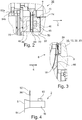
- the structure of the axial bearing 36 is based on the Fig. 2 to recognize.
- the two coils 46 are each arranged in a coil housing 48 which is approximately U-shaped when viewed in cross section.
- the bearing ring 50 penetrates into the space between the two coils 46.
- a distance a is formed between the bearing ring 50 and a respective coil 46.
- the coil housings 48 also seal the space between them in the radial direction.
- an intermediate piece 84 is arranged for this purpose, which is designed as a ring that adjoins the bearing ring 50 on the circumferential side.
- the intermediate piece 84 is arranged between the two coil housings 48 and sealed with sealing elements, especially O-rings 70.
- the left bobbin case 48 is still Sealed by an O-ring 70 to a further housing part of the generator housing 32.
- the axial position sensor 52a detects an axial distance value from the axial measuring ring 54a. This distance value is directly correlated to the distance a between the two coils 46 and the bearing ring 50.Based on the geometric relationships, the measured distance value can be clearly converted into the distance a between the turbine-side coil 46 and the bearing ring 50 on the one hand and the generator-side coil on the other to the bearing ring 50 assumes.
- the two distances can also differ. In the normal operating state, the distance is typically set such that the distance a to the two coils 46 is identical.
- a sealing element is arranged between the turbine wheel 16 and the annular flange 12 and has annular webs protruding in the axial direction. These annular webs engage in corresponding annular grooves on the back of the turbine wheel 16 and form the aforementioned labyrinth seal 24.
- the annular webs and the annular grooves are only arranged in the outermost circumferential area of the turbine wheel 16.
- a further gap 86 with a gap dimension s is formed between the turbine wheel 16 and the generator housing 32, that is to say specifically the annular flange 12.
- the sealing effect of the labyrinth seal 24 is defined by a gap, not shown here, between the annular webs and the annular grooves. This varies with a change in the gap dimension s of the gap 86, that is to say it is correlated with the gap dimension s.
- the turbine generator 2 is assigned a control device 90 which is preferably a direct component of the turbine generator 2.
- a control device 90 On the turbine part 8 there is a supply line 92 on the inlet side and a discharge line 94 on the outlet side for the Medium M connected.
- An example is in the Fig. 4 a flow valve 96 is arranged in the supply line 92.
- such a device can be arranged in addition or as an alternative in the discharge line 94.
- a pressure is formed on the rear side of the turbine wheel 16 on the generator side and a differential pressure ratio is established between the front side on the turbine side and this rear side of the turbine wheel 16.
- Different pressures lead to an axial force acting on the turbine wheel 16 and the generator shaft 14.
- the sealing arrangement 24 is preferably designed in such a way that the pressure conditions in normal operation on the front side and rear side are the same or as similar as possible, so that no differential pressure or, if possible, no differential pressure develops. As a result, no axial force or, if possible, no axial force is generated, and the axial bearing 36 does not have to absorb any or only small axial forces.
- varying process parameters such as varying speeds, varying pressure ratios, varying flow rates, varying temperatures, etc. can result in the gap dimension s between the turbine wheel 16 and the annular flange 12 varying.
- Varying process parameters i.e. unsteady operating states, occur, for example, when starting up. This can lead to a slight bending of the turbine wheel 16, which has a direct influence on the gap dimension s and the sealing effect of the labyrinth seal 24.
- the leakage current flowing through the further gap 86 changes, which leads to a change in the pressure conditions and especially the pressure difference between the front and the rear of the turbine wheel 16 and ultimately to an axial force resulting on the generator shaft 14.
- a regulation is first integrated in the control device 90, which controls the coil currents of the two coils 46 accordingly in order to set the distance a between the respective coils 46 and the bearing ring 50 to a desired predetermined setpoint. This is preferably selected such that the bearing ring 50 is arranged exactly in the middle between the coils 46.
- the control device 90 first switches from a normal operating mode to the optimized operating mode if, for example, a difference in the coil currents of the coils 46 of the axial bearing 36 is greater than 20% or greater than 30% of an average value of the coil currents of the two coils 46. If this measure is not sufficient, the safety mode is preferably initiated when a special safety-critical operating situation is reached.
- control device switches to the safety mode and emits the control signal S when one of the two coil currents of the two coils 46 exceeds a predetermined threshold, also referred to as the current threshold, of, for example, 75% of a maximum permissible coil current.
- a predetermined threshold also referred to as the current threshold
- the target value for the distance a is changed.
- an axial force is deliberately generated by changing the coil currents, so that the bearing ring 50 and thus the entire generator shaft 14 is displaced in or against the axial direction 6 relative to the stationary part 28.
- the change in the setpoint value for the distance a is such that - depending on the current operating situation - the gap dimension s is increased or decreased, specifically in such a way that the coil currents of the two coils 46 are equal.
- the new setpoint value a is set in such a way that the gap dimension s is reduced again. That is, the bearing ring 50 is deliberately offset in the axial direction 6 relative to the turbine part 8 by the axial bearing.
- This measure therefore directly influences the sealing effect of the labyrinth seal 24 via the variation of the setpoint value for the distance a, preferably in the direction of a bearing that is as free from axial forces as possible, or it is regulated to a maximum efficiency of the turbine generator 2.
- the control device 90 emits a control signal S with which the flow valve 96 is activated, for example, in order to reduce the mass flow for the medium M, for example.
- the speed of the turbine generator 2 is limited by the control.
- both variants are used, in particular, in combination, the setpoint value being varied initially - when the first triggering criterion is reached. Since this can only be varied within a limited range, since a distance must remain between the coils and the bearing ring 50, the additional measure according to the second variant may be necessary in unfavorable situations. This is therefore additionally initiated in particular when the setpoint has already reached a maximum permissible value and the second triggering criterion, namely the exceeding of the current threshold for the coil current, is also exceeded.
Landscapes
- Engineering & Computer Science (AREA)
- General Engineering & Computer Science (AREA)
- Mechanical Engineering (AREA)
- Power Engineering (AREA)
- Physics & Mathematics (AREA)
- Sustainable Development (AREA)
- Life Sciences & Earth Sciences (AREA)
- High Energy & Nuclear Physics (AREA)
- Electromagnetism (AREA)
- Sustainable Energy (AREA)
- Chemical & Material Sciences (AREA)
- Combustion & Propulsion (AREA)
- Connection Of Motors, Electrical Generators, Mechanical Devices, And The Like (AREA)
- Turbine Rotor Nozzle Sealing (AREA)
- Sealing Using Fluids, Sealing Without Contact, And Removal Of Oil (AREA)
- Magnetic Bearings And Hydrostatic Bearings (AREA)
- Sealing Of Bearings (AREA)
Claims (11)
- Générateur à turbine (2), conçu pour des vitesses supérieures à 4 000 tr/min, qui comporte une partie de turbine (8) et une partie de générateur (10) et s'étend le long d'un axe de rotation de la partie de turbine (8) à la partie de générateur (10), dans lequel- la partie de générateur (10) comporte une partie rotative (30) et une partie fixe (28),- la partie de turbine (8) comporte une roue de turbine (16) et une entrée (20) et une sortie (22) pour un milieu (M),- un dispositif d'étanchéité (24) est disposé entre la roue de turbine (16) et une partie fixe du boîtier,- la partie de générateur (10) comporte un arbre de générateur (14) avec au moins une bague de roulement (50),
caractérisé en ce
que- l'arbre de générateur (14) est monté par l'intermédiaire d'un palier axial (36) conçu comme un palier magnétique et, à cet effet, le palier magnétique comporte deux bobines (46) espacées axialement l'une de l'autre, entre lesquelles l'au moins une bague de palier (50) est disposée à une distance axiale (a) respective des bobines (46),- il est prévu un dispositif de commande (90) pour commander le palier axial (36), qui est configuré de telle sorte que la distance axiale (a) entre l'au moins une bague de palier (50) et l'une des bobines (46) est régulée à une valeur de consigne, et à cet effet, le dispositif de commande (90) est conçu pour appliquer un courant de bobine aux bobines (46) pendant le fonctionnement, les bobines (46) étant conçues pour un courant de bobine maximal,- dans lequel le dispositif de commande (90) est en outre configuré pour initier au moins une des deux actions suivantes selon les besoins, à savoir- il fait varier la valeur de consigne de telle sorte que l'effet d'étanchéité du dispositif d'étanchéité (24) est modifié et/ou- il émet un signal de commande (S) pour commander le débit du fluide (M) ou la vitesse du générateur à turbine (2) lorsqu'un seuil de courant pour le courant de la bobine est dépassé. - Générateur de turbine (2) selon la revendication 1, dans lequel par la modification de la valeur de consigne une dimension de fente (s) entre la partie de turbine (8) et la partie de boîtier fixe dans la zone du dispositif d'étanchéité (24) est modifiée.
- Générateur de turbine (2) selon l'une des revendications précédentes, dans lequel, pendant le fonctionnement, les deux bobines (46) génèrent respectivement des forces axiales, qui agissent sur l'au moins une bague de roulement (50), et le dispositif de commande (90) est configuré de telle sorte que la valeur de consigne est régulée de telle sorte que les forces axiales générées par les deux bobines (46) sont amenées en alignement.
- Générateur à turbine (2) selon l'une des revendications précédentes, dans lequel une variation maximale admissible dans la plage de +/- 0,5 mm est prédéterminée pour la modification de la consigne.
- Générateur à turbine (2) selon l'une des revendications précédentes, dans lequel le dispositif de commande (90) est conçu pour faire varier la consigne lorsqu'une différence entre les courants de bobine et/ou une valeur absolue d'au moins un des courants de bobine dépasse un seuil prédéterminé.
- Générateur à turbine (2) selon la revendication précédente, dans lequel le dispositif de commande (90) est configuré de telle sorte que la variation de la valeur de consigne est effectuée lorsque la différence entre les courants de bobine est supérieure à 20%, de préférence supérieure à 30% et en particulier dans la plage comprise entre 20% et 60% d'un courant de bobine moyen des deux bobines.
- Générateur de turbine (2) selon l'une des revendications précédentes, dans lequel le seuil de courant pour la sortie du signal de commande (S) est compris entre 60% et 85% et notamment à 75% du courant maximal admissible de la bobine.
- Générateur de turbine (2) selon l'une des revendications précédentes, dans lequel le dispositif de commande (90) est conçu de telle sorte que, lorsque la valeur seuil actuelle est dépassée, au moins l'une des mesures suivantes est initiée par le signal de commande (S) :- réduction du débit du fluide (M) en contrôlant une vanne de débit pour le fluide,- limitation et/ou réduction la vitesse actuelle- variation des conditions de pression à l'entrée et/ou à la sortie.
- Générateur à turbine (2) selon l'une des revendications précédentes, dans lequel un joint à labyrinthe (24) est formé en tant que dispositif d'étanchéité.
- Générateur à turbine (2) selon l'une des revendications précédentes, caractérisé en ce qu'il est conçu pour une vitesse de fonctionnement comprise entre 4 000 et 40 000 tr/min et en particulier la partie de turbine a un diamètre (d) compris entre 50 mm et 500 mm.
- Procédé de fonctionnement d'un générateur à turbine (2), qui comporte une partie de turbine (8) et une partie de générateur (10) et qui s'étend le long d'un axe de rotation de la partie de turbine (8) à la partie de générateur (10), dans lequel- la partie de générateur (10) a une partie rotative (30) et une partie fixe (28), et la partie rotative (30) tourne à une vitesse supérieure à 4 000 tr/min,- la partie de turbine (8) comporte une roue de turbine (16) et une entrée (20) et une sortie (22) pour un fluide (M), et un fluide (M) entre par l'entrée (20) et sort par la sortie (22),- un dispositif d'étanchéité (24) est disposé entre la partie de turbine (8) et une partie de boîtier fixe,- la partie de générateur (10) comporte un arbre de générateur (14) avec au moins une bague de roulement (50) et l'arbre de générateur (14) est monté par l'intermédiaire d'un palier axial (36) configuré comme un palier magnétique et, à cet effet, le palier axial (36) comporte deux bobines (46) espacées axialement l'une de l'autre, entre lesquelles la au moins une bague de roulement (50) est disposée à une distance axiale (a) respective des bobines (46),- dans lequel la distance axiale (a) entre la au moins une bague de roulement (50) et l'une des bobines est régulée à une valeur de consigne et, à cet effet, un courant de bobine est appliqué aux bobines (46), dans lequel les bobines (46) sont conçues pour un courant de bobine maximal et dans lequel, en outre, au moins l'une des mesures suivantes est réalisée :- la valeur de consigne est varié pour modifier l'effet d'étanchéité du dispositif d'étanchéité (24) et/ou- lorsqu'un seuil de courant pour le courant de bobine est dépassé, un signal de commande (S) est émis pour commander l'écoulement du milieu (M) ou la vitesse du générateur à turbine (2).
Applications Claiming Priority (2)
| Application Number | Priority Date | Filing Date | Title |
|---|---|---|---|
| DE102018206158.0A DE102018206158B4 (de) | 2018-04-20 | 2018-04-20 | Turbinengenerator sowie Verfahren zum Betrieb eines Turbinengenerators |
| PCT/EP2019/060033 WO2019202055A1 (fr) | 2018-04-20 | 2019-04-18 | Générateur à turbines et procédé de fonctionnement d'un générateur à turbine |
Publications (2)
| Publication Number | Publication Date |
|---|---|
| EP3781828A1 EP3781828A1 (fr) | 2021-02-24 |
| EP3781828B1 true EP3781828B1 (fr) | 2021-08-04 |
Family
ID=66286328
Family Applications (1)
| Application Number | Title | Priority Date | Filing Date |
|---|---|---|---|
| EP19719474.9A Active EP3781828B1 (fr) | 2018-04-20 | 2019-04-18 | Générateur à turbines et procédé d'opération d'un générateur à turbine |
Country Status (5)
| Country | Link |
|---|---|
| US (1) | US11105217B2 (fr) |
| EP (1) | EP3781828B1 (fr) |
| JP (1) | JP2021522460A (fr) |
| DE (1) | DE102018206158B4 (fr) |
| WO (1) | WO2019202055A1 (fr) |
Families Citing this family (1)
| Publication number | Priority date | Publication date | Assignee | Title |
|---|---|---|---|---|
| US11781556B2 (en) * | 2018-08-27 | 2023-10-10 | The Texas A&M University System | High energy density turbomachines |
Family Cites Families (12)
| Publication number | Priority date | Publication date | Assignee | Title |
|---|---|---|---|---|
| US4254312A (en) * | 1978-12-29 | 1981-03-03 | Eaton Corporation | Temperature compensated fill valve/pressure switch |
| DE3343186A1 (de) * | 1983-11-29 | 1985-06-05 | Fraunhofer-Gesellschaft zur Förderung der angewandten Forschung e.V., 8000 München | Magnetische rotorlagerung |
| WO1987000360A1 (fr) * | 1985-06-29 | 1987-01-15 | Hartmut Griepentrog | Machine comportant un rotor a paliers magnetiques et une machine electrique a champ radial |
| DE9215696U1 (de) * | 1992-11-18 | 1994-03-17 | Piller Gmbh Co Kg Anton | Stromgewinnungsanlage |
| DE4427153A1 (de) * | 1994-08-01 | 1996-02-08 | Balzers Pfeiffer Gmbh | Fluteinrichtung für magnetisch gelagerte Vakuumpumpen |
| JP3696398B2 (ja) * | 1997-04-28 | 2005-09-14 | Ntn株式会社 | 静圧磁気複合軸受およびスピンドル装置 |
| DE10005246C1 (de) * | 2000-02-05 | 2001-10-18 | Daimler Chrysler Ag | Abgasturbolader |
| JP2006230145A (ja) * | 2005-02-18 | 2006-08-31 | Ebara Corp | サブマージドタービン発電機 |
| DE202006018288U1 (de) * | 2006-12-01 | 2008-04-10 | Deprag Schulz Gmbh U. Co | Turbinengenerator zur Erzeugung elektrischer Energie sowie industrielle Anlage |
| DE102008035086B4 (de) * | 2008-07-28 | 2013-01-31 | Continental Automotive Gmbh | Turbolader mit einer Magnetlageranordnung zur Lagerung einer Welle des Turboladers und ein Verfahren zur Lagerung der Welle |
| US9234522B2 (en) * | 2012-01-03 | 2016-01-12 | United Technologies Corporation | Hybrid bearing turbomachine |
| DE102012211578B4 (de) * | 2012-07-04 | 2015-02-19 | Bmw Ag | Vorrichtung und Verfahren zur Nutzung von Abwärme eines Verbrennungsmotors insbesondere eines Kraftfahrzeugs sowie Turbine für eine solche Vorrichtung |
-
2018
- 2018-04-20 DE DE102018206158.0A patent/DE102018206158B4/de not_active Expired - Fee Related
-
2019
- 2019-04-18 EP EP19719474.9A patent/EP3781828B1/fr active Active
- 2019-04-18 WO PCT/EP2019/060033 patent/WO2019202055A1/fr active Application Filing
- 2019-04-18 JP JP2021506058A patent/JP2021522460A/ja active Pending
-
2020
- 2020-10-19 US US17/074,104 patent/US11105217B2/en active Active
Also Published As
| Publication number | Publication date |
|---|---|
| JP2021522460A (ja) | 2021-08-30 |
| WO2019202055A1 (fr) | 2019-10-24 |
| DE102018206158B4 (de) | 2020-02-06 |
| US11105217B2 (en) | 2021-08-31 |
| US20210033000A1 (en) | 2021-02-04 |
| EP3781828A1 (fr) | 2021-02-24 |
| DE102018206158A1 (de) | 2019-10-24 |
Similar Documents
| Publication | Publication Date | Title |
|---|---|---|
| EP2435664B1 (fr) | Système de contrôle de jeu pour une turbomachine | |
| DE69827318T2 (de) | Kombinierte, von aussen mit Druck beaufschlagte Gas-magnetische Lagervorrichtung und damit ausgestattete Spindeleinrichtung | |
| EP1945911B1 (fr) | Turbine à gaz | |
| WO2010136018A2 (fr) | Système de contrôle de jeu, turbomachine et procédé de réglage d'un jeu fonctionnel entre un rotor et une enveloppe d'une turbomachine | |
| DE60203959T2 (de) | Luftgekühltes Abgasgehäuse für eine Gasturbine | |
| CH697962B1 (de) | Innengehäuse für eine Rotationsmaschine, Rotationsmaschine und Verfahren zur Regelung eines Masses eines Mantelrings in einer Rotationsmaschine. | |
| EP2169282A1 (fr) | Agencement doté d'un joint d'étanchéité d'arbre | |
| EP1224381B1 (fr) | Dispositif pour compenser la poussee axiale dans des turbomachines | |
| DE3925403C2 (de) | Trockengasdichtung | |
| EP3781828B1 (fr) | Générateur à turbines et procédé d'opération d'un générateur à turbine | |
| DE102016207232A1 (de) | Elektrische Maschine | |
| DE69819293T2 (de) | Hydraulikdichtung | |
| EP1222400A1 (fr) | Procede et dispositif de refroidissement indirect de l'ecoulement dans des entrefers radiaux formes entre les rotors et les stators de turbomachines | |
| CH708441A2 (de) | Systeme und Verfahren betreffend die axiale Positionierung von Turbinengehäusen und den Schaufelspitzenspalt in Gasturbinen. | |
| EP0891471B1 (fr) | Procede et dispositif compensateurs de la poussee d'une turbomachine | |
| EP1154123A1 (fr) | Procédé de refroidissement pour l'arbre d'une turbine à vapeur à haute pression | |
| DE19609308A1 (de) | Vakuumpumpe mit Gewindekanal | |
| EP0173803B1 (fr) | Machine d'écoulement | |
| EP2347101B1 (fr) | Turbine à gaz et moteur à turbine à gaz associé | |
| EP0690204B1 (fr) | Turbine à vapeur ayant au moins deux joint pour assurer l'étanchéité du carter | |
| DE102012207019B4 (de) | Strömungsmaschine sowie Verfahren zur Kühlen einer solchen | |
| EP2318727B1 (fr) | Palier magnétique et procédé d'opération du palier magnétique | |
| EP3921523A1 (fr) | Installation de détente et installation de récupération d'énergie électrique à partir de chaleur | |
| WO2019001961A1 (fr) | Machine de compression | |
| DE3309812C2 (de) | Äußeres Gehäuse für ein Gasturbinentriebwerk |
Legal Events
| Date | Code | Title | Description |
|---|---|---|---|
| STAA | Information on the status of an ep patent application or granted ep patent |
Free format text: STATUS: UNKNOWN |
|
| STAA | Information on the status of an ep patent application or granted ep patent |
Free format text: STATUS: THE INTERNATIONAL PUBLICATION HAS BEEN MADE |
|
| PUAI | Public reference made under article 153(3) epc to a published international application that has entered the european phase |
Free format text: ORIGINAL CODE: 0009012 |
|
| STAA | Information on the status of an ep patent application or granted ep patent |
Free format text: STATUS: REQUEST FOR EXAMINATION WAS MADE |
|
| 17P | Request for examination filed |
Effective date: 20201029 |
|
| AK | Designated contracting states |
Kind code of ref document: A1 Designated state(s): AL AT BE BG CH CY CZ DE DK EE ES FI FR GB GR HR HU IE IS IT LI LT LU LV MC MK MT NL NO PL PT RO RS SE SI SK SM TR |
|
| AX | Request for extension of the european patent |
Extension state: BA ME |
|
| GRAP | Despatch of communication of intention to grant a patent |
Free format text: ORIGINAL CODE: EPIDOSNIGR1 |
|
| STAA | Information on the status of an ep patent application or granted ep patent |
Free format text: STATUS: GRANT OF PATENT IS INTENDED |
|
| INTG | Intention to grant announced |
Effective date: 20210315 |
|
| GRAS | Grant fee paid |
Free format text: ORIGINAL CODE: EPIDOSNIGR3 |
|
| GRAA | (expected) grant |
Free format text: ORIGINAL CODE: 0009210 |
|
| STAA | Information on the status of an ep patent application or granted ep patent |
Free format text: STATUS: THE PATENT HAS BEEN GRANTED |
|
| DAV | Request for validation of the european patent (deleted) | ||
| DAX | Request for extension of the european patent (deleted) | ||
| AK | Designated contracting states |
Kind code of ref document: B1 Designated state(s): AL AT BE BG CH CY CZ DE DK EE ES FI FR GB GR HR HU IE IS IT LI LT LU LV MC MK MT NL NO PL PT RO RS SE SI SK SM TR |
|
| REG | Reference to a national code |
Ref country code: GB Ref legal event code: FG4D Free format text: NOT ENGLISH |
|
| REG | Reference to a national code |
Ref country code: AT Ref legal event code: REF Ref document number: 1417267 Country of ref document: AT Kind code of ref document: T Effective date: 20210815 |
|
| REG | Reference to a national code |
Ref country code: CH Ref legal event code: EP |
|
| REG | Reference to a national code |
Ref country code: DE Ref legal event code: R096 Ref document number: 502019001970 Country of ref document: DE |
|
| REG | Reference to a national code |
Ref country code: IE Ref legal event code: FG4D Free format text: LANGUAGE OF EP DOCUMENT: GERMAN |
|
| REG | Reference to a national code |
Ref country code: SE Ref legal event code: TRGR |
|
| REG | Reference to a national code |
Ref country code: LT Ref legal event code: MG9D |
|
| REG | Reference to a national code |
Ref country code: NL Ref legal event code: MP Effective date: 20210804 |
|
| PG25 | Lapsed in a contracting state [announced via postgrant information from national office to epo] |
Ref country code: ES Free format text: LAPSE BECAUSE OF FAILURE TO SUBMIT A TRANSLATION OF THE DESCRIPTION OR TO PAY THE FEE WITHIN THE PRESCRIBED TIME-LIMIT Effective date: 20210804 Ref country code: RS Free format text: LAPSE BECAUSE OF FAILURE TO SUBMIT A TRANSLATION OF THE DESCRIPTION OR TO PAY THE FEE WITHIN THE PRESCRIBED TIME-LIMIT Effective date: 20210804 Ref country code: NO Free format text: LAPSE BECAUSE OF FAILURE TO SUBMIT A TRANSLATION OF THE DESCRIPTION OR TO PAY THE FEE WITHIN THE PRESCRIBED TIME-LIMIT Effective date: 20211104 Ref country code: PT Free format text: LAPSE BECAUSE OF FAILURE TO SUBMIT A TRANSLATION OF THE DESCRIPTION OR TO PAY THE FEE WITHIN THE PRESCRIBED TIME-LIMIT Effective date: 20211206 Ref country code: HR Free format text: LAPSE BECAUSE OF FAILURE TO SUBMIT A TRANSLATION OF THE DESCRIPTION OR TO PAY THE FEE WITHIN THE PRESCRIBED TIME-LIMIT Effective date: 20210804 Ref country code: FI Free format text: LAPSE BECAUSE OF FAILURE TO SUBMIT A TRANSLATION OF THE DESCRIPTION OR TO PAY THE FEE WITHIN THE PRESCRIBED TIME-LIMIT Effective date: 20210804 Ref country code: LT Free format text: LAPSE BECAUSE OF FAILURE TO SUBMIT A TRANSLATION OF THE DESCRIPTION OR TO PAY THE FEE WITHIN THE PRESCRIBED TIME-LIMIT Effective date: 20210804 Ref country code: BG Free format text: LAPSE BECAUSE OF FAILURE TO SUBMIT A TRANSLATION OF THE DESCRIPTION OR TO PAY THE FEE WITHIN THE PRESCRIBED TIME-LIMIT Effective date: 20211104 |
|
| PG25 | Lapsed in a contracting state [announced via postgrant information from national office to epo] |
Ref country code: PL Free format text: LAPSE BECAUSE OF FAILURE TO SUBMIT A TRANSLATION OF THE DESCRIPTION OR TO PAY THE FEE WITHIN THE PRESCRIBED TIME-LIMIT Effective date: 20210804 Ref country code: LV Free format text: LAPSE BECAUSE OF FAILURE TO SUBMIT A TRANSLATION OF THE DESCRIPTION OR TO PAY THE FEE WITHIN THE PRESCRIBED TIME-LIMIT Effective date: 20210804 Ref country code: GR Free format text: LAPSE BECAUSE OF FAILURE TO SUBMIT A TRANSLATION OF THE DESCRIPTION OR TO PAY THE FEE WITHIN THE PRESCRIBED TIME-LIMIT Effective date: 20211105 |
|
| PG25 | Lapsed in a contracting state [announced via postgrant information from national office to epo] |
Ref country code: NL Free format text: LAPSE BECAUSE OF FAILURE TO SUBMIT A TRANSLATION OF THE DESCRIPTION OR TO PAY THE FEE WITHIN THE PRESCRIBED TIME-LIMIT Effective date: 20210804 |
|
| PG25 | Lapsed in a contracting state [announced via postgrant information from national office to epo] |
Ref country code: DK Free format text: LAPSE BECAUSE OF FAILURE TO SUBMIT A TRANSLATION OF THE DESCRIPTION OR TO PAY THE FEE WITHIN THE PRESCRIBED TIME-LIMIT Effective date: 20210804 |
|
| REG | Reference to a national code |
Ref country code: DE Ref legal event code: R097 Ref document number: 502019001970 Country of ref document: DE |
|
| PG25 | Lapsed in a contracting state [announced via postgrant information from national office to epo] |
Ref country code: SM Free format text: LAPSE BECAUSE OF FAILURE TO SUBMIT A TRANSLATION OF THE DESCRIPTION OR TO PAY THE FEE WITHIN THE PRESCRIBED TIME-LIMIT Effective date: 20210804 Ref country code: SK Free format text: LAPSE BECAUSE OF FAILURE TO SUBMIT A TRANSLATION OF THE DESCRIPTION OR TO PAY THE FEE WITHIN THE PRESCRIBED TIME-LIMIT Effective date: 20210804 Ref country code: RO Free format text: LAPSE BECAUSE OF FAILURE TO SUBMIT A TRANSLATION OF THE DESCRIPTION OR TO PAY THE FEE WITHIN THE PRESCRIBED TIME-LIMIT Effective date: 20210804 Ref country code: EE Free format text: LAPSE BECAUSE OF FAILURE TO SUBMIT A TRANSLATION OF THE DESCRIPTION OR TO PAY THE FEE WITHIN THE PRESCRIBED TIME-LIMIT Effective date: 20210804 Ref country code: CZ Free format text: LAPSE BECAUSE OF FAILURE TO SUBMIT A TRANSLATION OF THE DESCRIPTION OR TO PAY THE FEE WITHIN THE PRESCRIBED TIME-LIMIT Effective date: 20210804 Ref country code: AL Free format text: LAPSE BECAUSE OF FAILURE TO SUBMIT A TRANSLATION OF THE DESCRIPTION OR TO PAY THE FEE WITHIN THE PRESCRIBED TIME-LIMIT Effective date: 20210804 |
|
| PLBE | No opposition filed within time limit |
Free format text: ORIGINAL CODE: 0009261 |
|
| STAA | Information on the status of an ep patent application or granted ep patent |
Free format text: STATUS: NO OPPOSITION FILED WITHIN TIME LIMIT |
|
| 26N | No opposition filed |
Effective date: 20220506 |
|
| PG25 | Lapsed in a contracting state [announced via postgrant information from national office to epo] |
Ref country code: IT Free format text: LAPSE BECAUSE OF FAILURE TO SUBMIT A TRANSLATION OF THE DESCRIPTION OR TO PAY THE FEE WITHIN THE PRESCRIBED TIME-LIMIT Effective date: 20210804 |
|
| PGFP | Annual fee paid to national office [announced via postgrant information from national office to epo] |
Ref country code: SE Payment date: 20220422 Year of fee payment: 4 |
|
| PGFP | Annual fee paid to national office [announced via postgrant information from national office to epo] |
Ref country code: IS Payment date: 20220413 Year of fee payment: 4 |
|
| REG | Reference to a national code |
Ref country code: CH Ref legal event code: PL |
|
| REG | Reference to a national code |
Ref country code: BE Ref legal event code: MM Effective date: 20220430 |
|
| PG25 | Lapsed in a contracting state [announced via postgrant information from national office to epo] |
Ref country code: MC Free format text: LAPSE BECAUSE OF FAILURE TO SUBMIT A TRANSLATION OF THE DESCRIPTION OR TO PAY THE FEE WITHIN THE PRESCRIBED TIME-LIMIT Effective date: 20210804 Ref country code: LU Free format text: LAPSE BECAUSE OF NON-PAYMENT OF DUE FEES Effective date: 20220418 Ref country code: LI Free format text: LAPSE BECAUSE OF NON-PAYMENT OF DUE FEES Effective date: 20220430 Ref country code: FR Free format text: LAPSE BECAUSE OF NON-PAYMENT OF DUE FEES Effective date: 20220430 Ref country code: CH Free format text: LAPSE BECAUSE OF NON-PAYMENT OF DUE FEES Effective date: 20220430 |
|
| PG25 | Lapsed in a contracting state [announced via postgrant information from national office to epo] |
Ref country code: BE Free format text: LAPSE BECAUSE OF NON-PAYMENT OF DUE FEES Effective date: 20220430 |
|
| PG25 | Lapsed in a contracting state [announced via postgrant information from national office to epo] |
Ref country code: IE Free format text: LAPSE BECAUSE OF NON-PAYMENT OF DUE FEES Effective date: 20220418 |
|
| P01 | Opt-out of the competence of the unified patent court (upc) registered |
Effective date: 20230527 |
|
| PGFP | Annual fee paid to national office [announced via postgrant information from national office to epo] |
Ref country code: DE Payment date: 20230424 Year of fee payment: 5 |
|
| REG | Reference to a national code |
Ref country code: SE Ref legal event code: EUG |
|
| GBPC | Gb: european patent ceased through non-payment of renewal fee |
Effective date: 20230418 |
|
| PG25 | Lapsed in a contracting state [announced via postgrant information from national office to epo] |
Ref country code: GB Free format text: LAPSE BECAUSE OF NON-PAYMENT OF DUE FEES Effective date: 20230418 |
|
| PG25 | Lapsed in a contracting state [announced via postgrant information from national office to epo] |
Ref country code: SE Free format text: LAPSE BECAUSE OF NON-PAYMENT OF DUE FEES Effective date: 20230419 Ref country code: GB Free format text: LAPSE BECAUSE OF NON-PAYMENT OF DUE FEES Effective date: 20230418 |
|
| PG25 | Lapsed in a contracting state [announced via postgrant information from national office to epo] |
Ref country code: MK Free format text: LAPSE BECAUSE OF FAILURE TO SUBMIT A TRANSLATION OF THE DESCRIPTION OR TO PAY THE FEE WITHIN THE PRESCRIBED TIME-LIMIT Effective date: 20210804 Ref country code: CY Free format text: LAPSE BECAUSE OF FAILURE TO SUBMIT A TRANSLATION OF THE DESCRIPTION OR TO PAY THE FEE WITHIN THE PRESCRIBED TIME-LIMIT Effective date: 20210804 |