EP1154123A1 - Procédé de refroidissement pour l'arbre d'une turbine à vapeur à haute pression - Google Patents
Procédé de refroidissement pour l'arbre d'une turbine à vapeur à haute pression Download PDFInfo
- Publication number
- EP1154123A1 EP1154123A1 EP00109911A EP00109911A EP1154123A1 EP 1154123 A1 EP1154123 A1 EP 1154123A1 EP 00109911 A EP00109911 A EP 00109911A EP 00109911 A EP00109911 A EP 00109911A EP 1154123 A1 EP1154123 A1 EP 1154123A1
- Authority
- EP
- European Patent Office
- Prior art keywords
- steam
- cooling
- expansion section
- pressure
- pressure expansion
- Prior art date
- Legal status (The legal status is an assumption and is not a legal conclusion. Google has not performed a legal analysis and makes no representation as to the accuracy of the status listed.)
- Withdrawn
Links
Images


Classifications
-
- F—MECHANICAL ENGINEERING; LIGHTING; HEATING; WEAPONS; BLASTING
- F01—MACHINES OR ENGINES IN GENERAL; ENGINE PLANTS IN GENERAL; STEAM ENGINES
- F01K—STEAM ENGINE PLANTS; STEAM ACCUMULATORS; ENGINE PLANTS NOT OTHERWISE PROVIDED FOR; ENGINES USING SPECIAL WORKING FLUIDS OR CYCLES
- F01K13/00—General layout or general methods of operation of complete plants
- F01K13/006—Auxiliaries or details not otherwise provided for
-
- F—MECHANICAL ENGINEERING; LIGHTING; HEATING; WEAPONS; BLASTING
- F01—MACHINES OR ENGINES IN GENERAL; ENGINE PLANTS IN GENERAL; STEAM ENGINES
- F01D—NON-POSITIVE DISPLACEMENT MACHINES OR ENGINES, e.g. STEAM TURBINES
- F01D25/00—Component parts, details, or accessories, not provided for in, or of interest apart from, other groups
- F01D25/08—Cooling; Heating; Heat-insulation
- F01D25/12—Cooling
-
- F—MECHANICAL ENGINEERING; LIGHTING; HEATING; WEAPONS; BLASTING
- F01—MACHINES OR ENGINES IN GENERAL; ENGINE PLANTS IN GENERAL; STEAM ENGINES
- F01D—NON-POSITIVE DISPLACEMENT MACHINES OR ENGINES, e.g. STEAM TURBINES
- F01D5/00—Blades; Blade-carrying members; Heating, heat-insulating, cooling or antivibration means on the blades or the members
- F01D5/02—Blade-carrying members, e.g. rotors
- F01D5/08—Heating, heat-insulating or cooling means
- F01D5/081—Cooling fluid being directed on the side of the rotor disc or at the roots of the blades
- F01D5/084—Cooling fluid being directed on the side of the rotor disc or at the roots of the blades the fluid circulating at the periphery of a multistage rotor, e.g. of drum type
Definitions
- the present invention relates to a method for cooling a shaft in a high pressure expansion section Steam turbine, with live steam in a steam generator a temperature and a pressure generated and the high pressure expansion section is fed. It continues to affect one High pressure expansion section of a steam turbine with one rotatably mounted shaft and a housing surrounding the shaft, the high pressure expansion section with a feed for supplying live steam at a temperature and a pressure from a steam generator.
- Each section becomes a high-pressure expansion section Steam turbine understood, in which live steam expands.
- Under an HD sub-turbine is understood to mean any sub-turbine, which is immediately supplied with live steam.
- the label "HD sub-turbine” therefore extends to Steam turbines in which the high pressure expansion with subsequent Expansion steps take place in a common housing, especially on a combined high-pressure medium-pressure turbine (HD / MD sub-turbine).
- One end face of the piston is used for thrust compensation charged with live steam. It is a relatively large one Area of exposure and thus a comparatively large Piston diameter required. Because of the high High centrifugal acceleration.
- the live steam is above that on the outer surface of the piston located shaft seal throttled and also wetted the rear bulkhead.
- the piston is therefore in operation exposed to high temperatures.
- the high temperatures lead to reduced strength of the piston. It lies therefore a high load with reduced strength.
- the piston is therefore subject to significant restrictions the material selection. As a rule, a high quality Material can be used. Because the piston in general is produced in one piece with the shaft, arise essentially increased costs.
- the live steam temperature can be reduced.
- the turbine output is reduced accordingly.
- a constant pressure stage can be installed which lowers the inlet temperature of the live steam. If this constant pressure level is not required for other reasons is, it represents an elaborate and at the same time only limited Solution represents.
- Another variant provides that Design pistons as stepped pistons. The necessary thrust compensation in the axial direction by several piston stages with increasing diameter. This increasing piston diameter can be realized because the temperature of the Live steam decreases during throttling. However, leads this solution for a widespread wetting of the housing Live steam, which makes this more expensive, or requires equalization lines with a large cross section for blading to a to ensure safe functioning.
- the thrust acting in the axial direction can also be constructive be circumvented.
- there is a double-flow HD turbine for this required the two outflows as well two separate blades on a continuous shaft having.
- the inflow is approximately in the middle of the Turbine arranged.
- the axial thrust that occurs during operation the left and right viewed along the turbine axis Half of the turbine balances each other. It is therefore no piston required for thrust compensation.
- the cost of blading and housing a double flow Turbine relatively high.
- the object of the present invention is therefore a cooling to enable a shaft of a high-pressure turbine, in particular cooling a piston for thrust compensation.
- this object is achieved in a method of type mentioned solved in that the steam generator cooling steam is removed for cooling, the temperature of which is lower and whose pressure is greater than that of live steam.
- the device according to the invention provides a solution to the problem before that the high pressure expansion section another feed for supplying cooling steam to the steam generator is taken and a lower temperature and one has greater pressure than the live steam.
- the cooling steam can be between a separator and a superheater of the steam generator. Alternative is also a withdrawal from a superheater of the steam generator possible between individual superheater elements.
- the pressure difference between the cooling steam and the live steam about the pressure loss of the bypassed superheater elements.
- the pressure of the cooling steam is around 1 to 10 bar, especially about 2 to 7 bar higher than that Live steam pressure.
- the temperature of the cooling steam is corresponding to the number of superheater elements bypassed than the temperature of the live steam. In both configurations becomes a cooling steam with a lower temperature and greater pressure than the live steam provided.
- the temperature of the cooling steam can, for example be between about 350 ° C to 500 ° C.
- the cooling steam is advantageous to the high-pressure expansion section in the vicinity of a feed for the live steam.
- the necessary cooling takes place in one area in which the temperature of the live steam is still relative is high. As a result, a high cooling effect is achieved.
- the cooling steam is in front of the Removal from the steam generator overheated. This prevents one impermissible condensation of water drops from the cooling steam.
- the extent of overheating depends on the particular one Boundary conditions.
- the high-pressure expansion section opens the supply for the cooling steam advantageously in a Ring groove on the housing, which is guided around the shaft.
- the Cooling steam is thus evenly spread over the entire circumference Distributed shaft and housing.
- the shaft is in the range of further feed designed as a piston to compensate of forces acting on blades in the axial direction the wave.
- the for Thrust compensation required pistons cooled directly. It can therefore a higher inlet temperature for the live steam or another material for the piston and thus the shaft to get voted.
- the leakage of live steam blocked or at least reduced via the shaft seal and thereby the efficiency of the high pressure expansion section improved.
- the feeder for the live steam and the further supply for the cooling steam arranged closely side by side.
- the seal lengths correspond the existing pressure conditions. This gives even with only slight temperature differences between Cooling steam and live steam provide an optimal cooling effect minimal cooling steam flow. Further cooling takes place in the thermally most stressed area of the HD wave.
- shielding of the Live steam from the shaft for example through a control stage, a diagonal step or a different cover.
- the cooling steam is advantageously added only immediately before or within the HD blading. In this way, further thermal Highly stressed areas of the HD wave and the HD blading cool.
- the housing advantageously has an outer part and an inner part on, and the feed runs at least partially between the outer part and the inner part. This will make the construction the housing and the supply of cooling steam enabled with little effort. In addition, a Cooling effect between the housing parts, that is between the Inner part and the outer part causes.
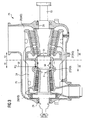
- FIG 1 is a steam turbine system with a Steam turbine 10 shown.
- the steam turbine 10 has one HP sub-turbine 11 and an MD / LP sub-turbine 12 with a common one Wave 13 on.
- the shaft 13 rotates as indicated schematically and drives a generator 14.
- Die Shaft 13 and generator 14 are not shown Connection coupled with each other.
- the one for operating the high-pressure turbine section 11 and the MD / LP turbine section 12 required steam is in a steam generator 15 generated with associated superheater.
- the steam flows through the HP partial turbine 11, possibly an intermediate overheating 21 and then the MD / ND sub-turbine 12.
- the one from the MD / ND sub-turbine 12 emerging steam is in a condenser 16 condensed and via pumps 17 through MD / ND preheaters 18 and HD preheater 19, 20 passed back to the steam generator 15.
- For Improving the efficiency of the steam turbine 10 is one Feed water preheating A, B, C, D, E, n provided.
- For loading the HD sub-turbine 11 and the MD / ND sub-turbine 12 serve schematically illustrated valves. It should be on this Place only the valves 43 and 44 described in more detail become.
- a mass flow m is fed to the steam generator 15.
- the main part of this mass flow m emerges from the steam generator 15 as live steam m 1 .
- the application of the HP sub-turbine 11 can be adjusted via the valve 43.
- cooling steam m 2 is taken from the steam generator 15 for cooling the HP sub-turbine 11.
- the amount of cooling steam m 2 is adjusted via the valve 44. In this way, the application of live steam m 1 and cooling steam m 2 to the HP partial turbine 11 can be optimally adapted to the prevailing boundary conditions.
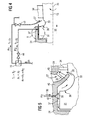
- FIG. 2 schematically shows a longitudinal section through the HP sub-turbine 11
- FIG. 3 shows a longitudinal section through a combined HD / MD sub-turbine 25 with an HD sub-turbine 11 and an MD sub-turbine 12.
- the shaft 13 is in a housing 22 with an outer part 23, an inner part 24 and a cover 26 added (so-called drum design of the high-pressure turbine section).
- An inflow 27 for the live steam m 1 and an outflow 28 are provided.
- inflow 27 and outflow 28 are correspondingly provided for the high-pressure turbine section 11 and the MD-section turbine 12.
- the assignment is made by specifying HD or MD after the respective reference symbol. Sealing from the environment is carried out by means of schematically illustrated seals 29.
- the live steam m 1 flows through the blading of the high-pressure sub-turbine 11 or the high-pressure / low-pressure sub-turbine 25 in the direction of the arrow 32.
- a force is generated in the direction of the arrow 32 in the axial direction the shaft 13 acts.
- a piston 31 is provided to compensate for the thrust generated from the HP blading.
- the piston 31 has a comparatively large diameter and is supplied with the fresh steam m 1 supplied. According to the invention, cooling of the piston 31 is therefore provided.
- the cooling steam m 2 is guided according to arrow 30 through the outer part 23. It then flows between the outer part 23 and the inner part 24 and is then guided radially inwards to the piston 31 and the piston 31 is acted upon by the cooling steam m 2 . In this way, effective cooling of the piston 31 is achieved.
- leakage of live steam m 1 via the piston 31 is blocked or at least reduced, and the efficiency of the high-pressure turbine section 11 is thus improved.
- FIG. 4 shows an enlarged representation of the detail X from FIG. 3 or FIG. 4 and FIG. 5 shows an enlarged representation of the detail Y from FIG. 4 with additional shielding of the live steam m 1 .
- the supply of live steam m 1 and cooling steam m 2 is also shown schematically.
- the temperature T 1 of the live steam m 1 is higher than the temperature T 2 of the cooling steam m 2 .
- the pressure p 2 of the cooling steam m 2 is greater than the pressure p 1 of the live steam m 1 .
- the live steam m 1 and the cooling steam m 2 together produce the mass flow m fed to the steam generator 15.
- the live steam flow m 1 is supplied as shown via the valve 43 and an inflow 27.
- the shaft 13 has a circumferential groove 33 next to the piston 31.
- the inflow 27 is limited by the inner part 24 and a shield 46.
- Guide blades 45 of the high-pressure turbine section 11 are arranged between the inner part 24 and the shield 46.
- the cooling steam m 2 flows according to arrow 30 between the shield 46 and the shaft 13 to the rotor blades 34 and prevents leaks of the live steam m 1 .
- a portion of the cooling steam m 2 emerges immediately before or in the area of the guide vanes 45.
- the shield 46 prevents direct wetting of the HD shaft 13 in the region of the circumferential groove 33.
- the live steam m 1 flows through the blading and thereby causes a force in the direction of the arrow 32. At the same time, it presses on an end face 36 of the groove 33 and thereby generates a counterforce.
- the end face 36 is chosen so that the force on the blades 34 and the force on the end face 36 approximately or completely equalize.
- the piston 31 must therefore absorb forces in the direction of the arrow 32 and is simultaneously subjected to live steam m 1 at high temperature T 1 .
- cooling by means of cooling steam m 2 is therefore provided, the cooling steam m 2 being removed from the steam generator 15.
- the amount of cooling steam m 2 is adjusted via the valve 44.
- the cooling steam m 2 then flows into an annular gap 37 between the piston 31 and the inner part 24 of the housing 22.
- One or more feeds 42 for the cooling steam m 2 are provided which open into an annular groove 38 of the inner part 24.
- the cooling steam m 2 is thus distributed uniformly over the entire circumference of the piston 31.
- the exact location and dimensions of the annular groove 38 depend on the individual case.
- the position of the annular groove 38 is advantageously chosen so that the incoming cooling steam m 2 is thrust-neutral. This variant is particularly advantageous when retrofitting in existing steam turbines 10.
- the steam mass flow of cooling steam m 2 is kept as small as possible for reasons of efficiency. It is advantageously chosen so that a safe blocking of the live steam m 1 is just achieved.
- the ratio of cooling steam mass flow to live steam mass flow is set here between approximately 0.1% to 1.5%, in particular between approximately 0.5% to 0.8%, depending on the performance class of the steam turbine system.
- the inflow 27 for the live steam m 1 and the feed 42 for the cooling steam m 2 are arranged closely next to one another.
- the cooling steam m 2 thus effects efficient cooling of the thermally highly stressed piston 31. Furthermore, leakage currents of live steam m 1 through the gap 37 between the piston 31 and the inner part 24 of the housing 22 are reliably prevented by utilizing the blocking effect of the cooling steam m 2 . Therefore, the efficiency of the high-pressure turbine section 11 increases.
- the supply 42 for the cooling steam m 2 through the housing 22 is designed to be heat-mobile.
- thermal deformations of the outer part 23 and the inner part 24 are compensated, in particular also possible thermally induced stresses (thermal stresses) between the housing 22 and the feed 42 are limited.
- Such feeds are known to a person skilled in the art in a number of configurations and are therefore not explained in more detail.
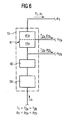
- FIG. 6 schematically shows a steam generator 15 with an evaporator 39, a separator 40 and a superheater 41.
- the mass flow m supplied is converted into the vapor phase. Any water drops contained are separated in the separator 40.
- the steam is then fed to the superheater 41 with superheater elements 41a, 41b.
- the temperature of the steam is increased in the superheater 41.
- the pressure decreases due to the flow resistance of the superheater elements 41a, 41b.
- the cooling steam can be removed from the steam generator 15, for example, between the superheater elements 41a, 41b.
- the cooling steam m 2a is overheated and has a temperature T 2a and a pressure p 2a .
- Overheating of the cooling steam m 2a before removal from the steam generator 15 prevents inadmissible condensation of water drops from the cooling steam m 2a .
- the extent of the overheating required depends on the boundary conditions.
- the difference between the temperatures T 1 , T 2a and the pressures P 1 and p 2a of the live steam m 1 and the cooling steam m 2a depends on the number of bypassed (not flowed through) superheater elements 41b.
- the cooling steam m 2b between the separator 40 and the superheater 42 can be removed from the steam generator 15.
- the differences in temperature T 1 , T 2b and pressure p 1 and p 2b again result from the number of bypassed (not flowed through) superheater elements 41a, 41b.
- the temperature T 2a , T 2b of the cooling steam m 2a , m 2b is lower than the temperature T 1 of the live steam m 1 .
- the cooling steam m 2a , m 2b has a greater pressure p 2a , p 2b than the live steam m 1 .
- the removal of cooling steam m 2 from the steam generator 15 is provided for the first time with the method and the device of the invention.
- the temperature T 2 of the cooling steam m 2 is lower and the pressure p 2 higher than that of the live steam m 1 . This enables simple cooling of the high-pressure shaft 13, in particular very efficient cooling of the piston 31 for thrust compensation.
Landscapes
- Engineering & Computer Science (AREA)
- Mechanical Engineering (AREA)
- General Engineering & Computer Science (AREA)
- Chemical & Material Sciences (AREA)
- Combustion & Propulsion (AREA)
- Turbine Rotor Nozzle Sealing (AREA)
Priority Applications (3)
| Application Number | Priority Date | Filing Date | Title |
|---|---|---|---|
| EP00109911A EP1154123A1 (fr) | 2000-05-10 | 2000-05-10 | Procédé de refroidissement pour l'arbre d'une turbine à vapeur à haute pression |
| PCT/EP2001/004795 WO2001086121A1 (fr) | 2000-05-10 | 2001-04-27 | Procede pour le refroidissement d'un arbre dans un segment d'expansion haute pression d'une turbine a vapeur |
| EP01936293A EP1280980A1 (fr) | 2000-05-10 | 2001-04-27 | Procede pour le refroidissement d'un arbre dans un segment d'expansion haute pression d'une turbine a vapeur |
Applications Claiming Priority (1)
| Application Number | Priority Date | Filing Date | Title |
|---|---|---|---|
| EP00109911A EP1154123A1 (fr) | 2000-05-10 | 2000-05-10 | Procédé de refroidissement pour l'arbre d'une turbine à vapeur à haute pression |
Publications (1)
| Publication Number | Publication Date |
|---|---|
| EP1154123A1 true EP1154123A1 (fr) | 2001-11-14 |
Family
ID=8168668
Family Applications (2)
| Application Number | Title | Priority Date | Filing Date |
|---|---|---|---|
| EP00109911A Withdrawn EP1154123A1 (fr) | 2000-05-10 | 2000-05-10 | Procédé de refroidissement pour l'arbre d'une turbine à vapeur à haute pression |
| EP01936293A Withdrawn EP1280980A1 (fr) | 2000-05-10 | 2001-04-27 | Procede pour le refroidissement d'un arbre dans un segment d'expansion haute pression d'une turbine a vapeur |
Family Applications After (1)
| Application Number | Title | Priority Date | Filing Date |
|---|---|---|---|
| EP01936293A Withdrawn EP1280980A1 (fr) | 2000-05-10 | 2001-04-27 | Procede pour le refroidissement d'un arbre dans un segment d'expansion haute pression d'une turbine a vapeur |
Country Status (2)
| Country | Link |
|---|---|
| EP (2) | EP1154123A1 (fr) |
| WO (1) | WO2001086121A1 (fr) |
Cited By (12)
| Publication number | Priority date | Publication date | Assignee | Title |
|---|---|---|---|---|
| EP1455066A1 (fr) * | 2003-03-06 | 2004-09-08 | Siemens Aktiengesellschaft | Méthode et dispositif de refroidissement d'une turbomachine |
| EP1674669A1 (fr) * | 2004-12-21 | 2006-06-28 | Siemens Aktiengesellschaft | Procédé de refroidissement de turbine à vapeur |
| US7086828B2 (en) | 2003-02-05 | 2006-08-08 | Siemens Aktiengesellschaft | Steam turbine and method for operating a steam turbine |
| US7101144B2 (en) | 2003-02-05 | 2006-09-05 | Siemens Aktiengesellschaft | Steam turbine rotor, steam turbine and method for actively cooling a steam turbine rotor and use of active cooling |
| EP1780376A1 (fr) * | 2005-10-31 | 2007-05-02 | Siemens Aktiengesellschaft | Turbine à vapeur |
| EP1788191A1 (fr) * | 2005-11-18 | 2007-05-23 | Siemens Aktiengesellschaft | Turbine à vapeur et procédé pour le refroidissement d'une turbine à vapeur |
| EP2031183A1 (fr) * | 2007-08-28 | 2009-03-04 | Siemens Aktiengesellschaft | Arbre de turbine à vapeur doté d'une couche d'isolation thermique |
| FR2934312A1 (fr) * | 2008-07-24 | 2010-01-29 | Gen Electric | Systeme et procede pour fournir de la vapeur de refroidissement surcritique dans l'espace de passage de roue d'une turbine |
| CH701914A1 (de) * | 2009-09-30 | 2011-03-31 | Alstom Technology Ltd | Dampfturbine mit Entlastungsnut am Rotor im Bereich des Schubausgleichskolbens. |
| US20110247330A1 (en) * | 2010-04-07 | 2011-10-13 | Kabushiki Kaisha Toshiba | Steam turbine plant |
| US8202037B2 (en) | 2004-08-02 | 2012-06-19 | Siemens Aktiengesellschaft | Steam turbine and method for operation of a steam turbine |
| EP2518277A4 (fr) * | 2009-12-21 | 2017-04-19 | Mitsubishi Hitachi Power Systems, Ltd. | Procédé et dispositif de refroidissement dans une turbine simple flux |
Families Citing this family (1)
| Publication number | Priority date | Publication date | Assignee | Title |
|---|---|---|---|---|
| EP2565419A1 (fr) * | 2011-08-30 | 2013-03-06 | Siemens Aktiengesellschaft | Refroidissement d'une turbomachine |
Citations (7)
| Publication number | Priority date | Publication date | Assignee | Title |
|---|---|---|---|---|
| DE6809708U (de) | 1968-12-03 | 1973-03-08 | Siemens Ag | Mehrschalige axiale, drosselgeregelte dampfturbine fuer hohe druecke und temperaturen. |
| JPS5510058A (en) * | 1978-07-10 | 1980-01-24 | Hitachi Ltd | Revolution-shaft cooling method for high pressure turbine |
| JPS58113501A (ja) * | 1981-12-28 | 1983-07-06 | Toshiba Corp | 蒸気タ−ビンの冷却装置 |
| JPS58202311A (ja) * | 1982-05-21 | 1983-11-25 | Hitachi Ltd | 蒸気タ−ビン冷却系統 |
| JPH09317405A (ja) * | 1996-05-29 | 1997-12-09 | Toshiba Corp | 蒸気タービンの高圧初段動翼植込部の冷却装置 |
| DE19701020A1 (de) | 1997-01-14 | 1998-07-23 | Siemens Ag | Dampfturbine |
| DE19823251C1 (de) | 1998-05-26 | 1999-07-08 | Siemens Ag | Verfahren und Vorrichtung zur Kühlung einer Niederdruckstufe einer Dampfturbine |
-
2000
- 2000-05-10 EP EP00109911A patent/EP1154123A1/fr not_active Withdrawn
-
2001
- 2001-04-27 EP EP01936293A patent/EP1280980A1/fr not_active Withdrawn
- 2001-04-27 WO PCT/EP2001/004795 patent/WO2001086121A1/fr not_active Application Discontinuation
Patent Citations (7)
| Publication number | Priority date | Publication date | Assignee | Title |
|---|---|---|---|---|
| DE6809708U (de) | 1968-12-03 | 1973-03-08 | Siemens Ag | Mehrschalige axiale, drosselgeregelte dampfturbine fuer hohe druecke und temperaturen. |
| JPS5510058A (en) * | 1978-07-10 | 1980-01-24 | Hitachi Ltd | Revolution-shaft cooling method for high pressure turbine |
| JPS58113501A (ja) * | 1981-12-28 | 1983-07-06 | Toshiba Corp | 蒸気タ−ビンの冷却装置 |
| JPS58202311A (ja) * | 1982-05-21 | 1983-11-25 | Hitachi Ltd | 蒸気タ−ビン冷却系統 |
| JPH09317405A (ja) * | 1996-05-29 | 1997-12-09 | Toshiba Corp | 蒸気タービンの高圧初段動翼植込部の冷却装置 |
| DE19701020A1 (de) | 1997-01-14 | 1998-07-23 | Siemens Ag | Dampfturbine |
| DE19823251C1 (de) | 1998-05-26 | 1999-07-08 | Siemens Ag | Verfahren und Vorrichtung zur Kühlung einer Niederdruckstufe einer Dampfturbine |
Non-Patent Citations (4)
| Title |
|---|
| PATENT ABSTRACTS OF JAPAN vol. 004, no. 037 (M - 004) 27 March 1980 (1980-03-27) * |
| PATENT ABSTRACTS OF JAPAN vol. 007, no. 221 (M - 246) 30 September 1983 (1983-09-30) * |
| PATENT ABSTRACTS OF JAPAN vol. 008, no. 047 (M - 280) 2 March 1984 (1984-03-02) * |
| PATENT ABSTRACTS OF JAPAN vol. 1998, no. 04 31 March 1998 (1998-03-31) * |
Cited By (22)
| Publication number | Priority date | Publication date | Assignee | Title |
|---|---|---|---|---|
| US7086828B2 (en) | 2003-02-05 | 2006-08-08 | Siemens Aktiengesellschaft | Steam turbine and method for operating a steam turbine |
| US7101144B2 (en) | 2003-02-05 | 2006-09-05 | Siemens Aktiengesellschaft | Steam turbine rotor, steam turbine and method for actively cooling a steam turbine rotor and use of active cooling |
| US7264438B2 (en) | 2003-03-06 | 2007-09-04 | Siemens Aktiengesellschaft | Method for cooling a turbo machine and turbo machine |
| EP1455066A1 (fr) * | 2003-03-06 | 2004-09-08 | Siemens Aktiengesellschaft | Méthode et dispositif de refroidissement d'une turbomachine |
| CN100420835C (zh) * | 2003-03-06 | 2008-09-24 | 西门子公司 | 用于冷却涡轮机的方法以及实施该方法的涡轮机 |
| US8202037B2 (en) | 2004-08-02 | 2012-06-19 | Siemens Aktiengesellschaft | Steam turbine and method for operation of a steam turbine |
| EP1674669A1 (fr) * | 2004-12-21 | 2006-06-28 | Siemens Aktiengesellschaft | Procédé de refroidissement de turbine à vapeur |
| US8128341B2 (en) | 2005-10-31 | 2012-03-06 | Siemens Aktiengesellschaft | Steam turbine |
| CN101300405B (zh) * | 2005-10-31 | 2013-05-29 | 西门子公司 | 汽轮机 |
| EP1780376A1 (fr) * | 2005-10-31 | 2007-05-02 | Siemens Aktiengesellschaft | Turbine à vapeur |
| WO2007051733A1 (fr) * | 2005-10-31 | 2007-05-10 | Siemens Aktiengesellschaft | Turbine à gaz |
| KR101014151B1 (ko) * | 2005-10-31 | 2011-02-14 | 지멘스 악티엔게젤샤프트 | 증기 터빈 |
| EP1788191A1 (fr) * | 2005-11-18 | 2007-05-23 | Siemens Aktiengesellschaft | Turbine à vapeur et procédé pour le refroidissement d'une turbine à vapeur |
| EP2031183A1 (fr) * | 2007-08-28 | 2009-03-04 | Siemens Aktiengesellschaft | Arbre de turbine à vapeur doté d'une couche d'isolation thermique |
| FR2934312A1 (fr) * | 2008-07-24 | 2010-01-29 | Gen Electric | Systeme et procede pour fournir de la vapeur de refroidissement surcritique dans l'espace de passage de roue d'une turbine |
| CH701914A1 (de) * | 2009-09-30 | 2011-03-31 | Alstom Technology Ltd | Dampfturbine mit Entlastungsnut am Rotor im Bereich des Schubausgleichskolbens. |
| JP2011074920A (ja) * | 2009-09-30 | 2011-04-14 | Alstom Technology Ltd | ロータに応力緩和溝を有する蒸気タービン |
| US8684663B2 (en) | 2009-09-30 | 2014-04-01 | Alstom Technology Ltd. | Steam turbine with relief groove on the rotor |
| DE102010046714B4 (de) | 2009-09-30 | 2021-07-29 | General Electric Technology Gmbh | Dampfturbine mit Entlastungsnut am Rotor |
| EP2518277A4 (fr) * | 2009-12-21 | 2017-04-19 | Mitsubishi Hitachi Power Systems, Ltd. | Procédé et dispositif de refroidissement dans une turbine simple flux |
| US20110247330A1 (en) * | 2010-04-07 | 2011-10-13 | Kabushiki Kaisha Toshiba | Steam turbine plant |
| US9664071B2 (en) * | 2010-04-07 | 2017-05-30 | Kabushiki Kaisha Toshiba | Steam turbine plant |
Also Published As
| Publication number | Publication date |
|---|---|
| WO2001086121A1 (fr) | 2001-11-15 |
| EP1280980A1 (fr) | 2003-02-05 |
Similar Documents
| Publication | Publication Date | Title |
|---|---|---|
| EP0900322B1 (fr) | Arbre de turbine et procede de refroidissement d'un arbre de turbine | |
| EP1154123A1 (fr) | Procédé de refroidissement pour l'arbre d'une turbine à vapeur à haute pression | |
| DE102014115962A1 (de) | Ansaugdichtungsanordnung einer Rotationsmaschine und Verfahren zur Montage derselben | |
| DE1961321A1 (de) | Dichtung fuer eine Gasturbine | |
| DE69203782T2 (de) | Zusammenbau eines Stators für eine rotierende Maschine. | |
| WO2013127837A1 (fr) | Turbomachine avec chapeau de carter équilibré en température | |
| EP1206627A1 (fr) | Turbine et procede pour evacuer du fluide de fuite | |
| DE102013219771B4 (de) | Dampfturbine | |
| WO2004003346A1 (fr) | Turbine a vapeur | |
| DE102010036071A1 (de) | Gehäuseseitige Struktur einer Turbomaschine | |
| WO1997038209A1 (fr) | Procede et dispositif compensateurs de la poussee d'une turbomachine | |
| WO2010091941A1 (fr) | Turbine à vapeur à triple enveloppe | |
| EP2324208B1 (fr) | Support d'aube directrice de turbine pour une turbine à gaz | |
| EP2310633B1 (fr) | Réduction de la charge thermique d'un boîtier extérieur pour une turbomachine | |
| EP1788191B1 (fr) | Turbine à vapeur et procédé pour le refroidissement d'une turbine à vapeur | |
| EP2274504B1 (fr) | Turbine à vapeur dotée d'un dispositif de refroidissement | |
| DE69013212T2 (de) | Pumpe mit Kühlungsmitteln für die Abdichtung. | |
| EP3183426B1 (fr) | Refroidissement contrôlé d'arbres de turbines | |
| EP3850194B1 (fr) | Turbine à vapeur et procédé permettant de faire fonctionner celle-ci | |
| EP2173973B1 (fr) | Conduite de vapeur pour une turbine à vapeur | |
| EP1674669A1 (fr) | Procédé de refroidissement de turbine à vapeur | |
| DE3218805A1 (de) | Dampfturbine | |
| WO2010023036A1 (fr) | Support d'aubes directrices pour une turbine à gaz | |
| EP2336506A1 (fr) | Turbine a vapeur dans une construction à trois coque | |
| EP2487337A1 (fr) | Turbine à vapeur en construction à trois coquilles |
Legal Events
| Date | Code | Title | Description |
|---|---|---|---|
| PUAI | Public reference made under article 153(3) epc to a published international application that has entered the european phase |
Free format text: ORIGINAL CODE: 0009012 |
|
| AK | Designated contracting states |
Kind code of ref document: A1 Designated state(s): AT BE CH CY DE DK ES FI FR GB GR IE IT LI LU MC NL PT SE |
|
| AX | Request for extension of the european patent |
Free format text: AL;LT;LV;MK;RO;SI |
|
| AKX | Designation fees paid | ||
| REG | Reference to a national code |
Ref country code: DE Ref legal event code: 8566 |
|
| STAA | Information on the status of an ep patent application or granted ep patent |
Free format text: STATUS: THE APPLICATION IS DEEMED TO BE WITHDRAWN |
|
| 18D | Application deemed to be withdrawn |
Effective date: 20020515 |