EP3781828B1 - Turbine generator and method for operating a turbine generator - Google Patents
Turbine generator and method for operating a turbine generator Download PDFInfo
- Publication number
- EP3781828B1 EP3781828B1 EP19719474.9A EP19719474A EP3781828B1 EP 3781828 B1 EP3781828 B1 EP 3781828B1 EP 19719474 A EP19719474 A EP 19719474A EP 3781828 B1 EP3781828 B1 EP 3781828B1
- Authority
- EP
- European Patent Office
- Prior art keywords
- turbine
- generator
- coils
- axial
- bearing
- Prior art date
- Legal status (The legal status is an assumption and is not a legal conclusion. Google has not performed a legal analysis and makes no representation as to the accuracy of the status listed.)
- Active
Links
- 238000000034 method Methods 0.000 title claims description 12
- 238000007789 sealing Methods 0.000 claims description 44
- 230000008859 change Effects 0.000 claims description 18
- 230000000694 effects Effects 0.000 claims description 17
- 230000001105 regulatory effect Effects 0.000 claims description 8
- 230000001276 controlling effect Effects 0.000 claims description 7
- 230000000670 limiting effect Effects 0.000 claims description 2
- 230000008569 process Effects 0.000 description 6
- 238000001816 cooling Methods 0.000 description 5
- 230000002829 reductive effect Effects 0.000 description 5
- 230000033228 biological regulation Effects 0.000 description 3
- 239000002826 coolant Substances 0.000 description 3
- 230000002596 correlated effect Effects 0.000 description 3
- 238000013461 design Methods 0.000 description 3
- 238000005259 measurement Methods 0.000 description 3
- 230000000875 corresponding effect Effects 0.000 description 2
- 238000011161 development Methods 0.000 description 2
- 230000018109 developmental process Effects 0.000 description 2
- 238000012546 transfer Methods 0.000 description 2
- MMOXZBCLCQITDF-UHFFFAOYSA-N N,N-diethyl-m-toluamide Chemical compound CCN(CC)C(=O)C1=CC=CC(C)=C1 MMOXZBCLCQITDF-UHFFFAOYSA-N 0.000 description 1
- 240000001439 Opuntia Species 0.000 description 1
- 235000004727 Opuntia ficus indica Nutrition 0.000 description 1
- 241000307523 Xenostegia media Species 0.000 description 1
- 238000013459 approach Methods 0.000 description 1
- 230000004323 axial length Effects 0.000 description 1
- 238000005452 bending Methods 0.000 description 1
- 230000007423 decrease Effects 0.000 description 1
- 230000003247 decreasing effect Effects 0.000 description 1
- 238000009795 derivation Methods 0.000 description 1
- 238000010586 diagram Methods 0.000 description 1
- 238000006073 displacement reaction Methods 0.000 description 1
- 239000007789 gas Substances 0.000 description 1
- 230000000977 initiatory effect Effects 0.000 description 1
- 238000004519 manufacturing process Methods 0.000 description 1
- 230000036961 partial effect Effects 0.000 description 1
- 230000001681 protective effect Effects 0.000 description 1
- 238000011084 recovery Methods 0.000 description 1
- 230000009467 reduction Effects 0.000 description 1
- 239000003507 refrigerant Substances 0.000 description 1
- 239000013589 supplement Substances 0.000 description 1
- 230000007704 transition Effects 0.000 description 1
- 238000011144 upstream manufacturing Methods 0.000 description 1
- 239000002918 waste heat Substances 0.000 description 1
- 238000004804 winding Methods 0.000 description 1
Images


Classifications
-
- F—MECHANICAL ENGINEERING; LIGHTING; HEATING; WEAPONS; BLASTING
- F01—MACHINES OR ENGINES IN GENERAL; ENGINE PLANTS IN GENERAL; STEAM ENGINES
- F01D—NON-POSITIVE DISPLACEMENT MACHINES OR ENGINES, e.g. STEAM TURBINES
- F01D15/00—Adaptations of machines or engines for special use; Combinations of engines with devices driven thereby
- F01D15/10—Adaptations for driving, or combinations with, electric generators
-
- F—MECHANICAL ENGINEERING; LIGHTING; HEATING; WEAPONS; BLASTING
- F16—ENGINEERING ELEMENTS AND UNITS; GENERAL MEASURES FOR PRODUCING AND MAINTAINING EFFECTIVE FUNCTIONING OF MACHINES OR INSTALLATIONS; THERMAL INSULATION IN GENERAL
- F16C—SHAFTS; FLEXIBLE SHAFTS; ELEMENTS OR CRANKSHAFT MECHANISMS; ROTARY BODIES OTHER THAN GEARING ELEMENTS; BEARINGS
- F16C32/00—Bearings not otherwise provided for
- F16C32/04—Bearings not otherwise provided for using magnetic or electric supporting means
- F16C32/0406—Magnetic bearings
- F16C32/044—Active magnetic bearings
- F16C32/0442—Active magnetic bearings with devices affected by abnormal, undesired or non-standard conditions such as shock-load, power outage, start-up or touchdown
-
- F—MECHANICAL ENGINEERING; LIGHTING; HEATING; WEAPONS; BLASTING
- F01—MACHINES OR ENGINES IN GENERAL; ENGINE PLANTS IN GENERAL; STEAM ENGINES
- F01D—NON-POSITIVE DISPLACEMENT MACHINES OR ENGINES, e.g. STEAM TURBINES
- F01D25/00—Component parts, details, or accessories, not provided for in, or of interest apart from, other groups
- F01D25/16—Arrangement of bearings; Supporting or mounting bearings in casings
-
- F—MECHANICAL ENGINEERING; LIGHTING; HEATING; WEAPONS; BLASTING
- F01—MACHINES OR ENGINES IN GENERAL; ENGINE PLANTS IN GENERAL; STEAM ENGINES
- F01D—NON-POSITIVE DISPLACEMENT MACHINES OR ENGINES, e.g. STEAM TURBINES
- F01D25/00—Component parts, details, or accessories, not provided for in, or of interest apart from, other groups
- F01D25/18—Lubricating arrangements
- F01D25/183—Sealing means
-
- F—MECHANICAL ENGINEERING; LIGHTING; HEATING; WEAPONS; BLASTING
- F02—COMBUSTION ENGINES; HOT-GAS OR COMBUSTION-PRODUCT ENGINE PLANTS
- F02C—GAS-TURBINE PLANTS; AIR INTAKES FOR JET-PROPULSION PLANTS; CONTROLLING FUEL SUPPLY IN AIR-BREATHING JET-PROPULSION PLANTS
- F02C1/00—Gas-turbine plants characterised by the use of hot gases or unheated pressurised gases, as the working fluid
- F02C1/04—Gas-turbine plants characterised by the use of hot gases or unheated pressurised gases, as the working fluid the working fluid being heated indirectly
- F02C1/05—Gas-turbine plants characterised by the use of hot gases or unheated pressurised gases, as the working fluid the working fluid being heated indirectly characterised by the type or source of heat, e.g. using nuclear or solar energy
-
- F—MECHANICAL ENGINEERING; LIGHTING; HEATING; WEAPONS; BLASTING
- F16—ENGINEERING ELEMENTS AND UNITS; GENERAL MEASURES FOR PRODUCING AND MAINTAINING EFFECTIVE FUNCTIONING OF MACHINES OR INSTALLATIONS; THERMAL INSULATION IN GENERAL
- F16C—SHAFTS; FLEXIBLE SHAFTS; ELEMENTS OR CRANKSHAFT MECHANISMS; ROTARY BODIES OTHER THAN GEARING ELEMENTS; BEARINGS
- F16C32/00—Bearings not otherwise provided for
- F16C32/04—Bearings not otherwise provided for using magnetic or electric supporting means
- F16C32/0406—Magnetic bearings
- F16C32/0408—Passive magnetic bearings
- F16C32/041—Passive magnetic bearings with permanent magnets on one part attracting the other part
- F16C32/0417—Passive magnetic bearings with permanent magnets on one part attracting the other part for axial load mainly
-
- F—MECHANICAL ENGINEERING; LIGHTING; HEATING; WEAPONS; BLASTING
- F16—ENGINEERING ELEMENTS AND UNITS; GENERAL MEASURES FOR PRODUCING AND MAINTAINING EFFECTIVE FUNCTIONING OF MACHINES OR INSTALLATIONS; THERMAL INSULATION IN GENERAL
- F16C—SHAFTS; FLEXIBLE SHAFTS; ELEMENTS OR CRANKSHAFT MECHANISMS; ROTARY BODIES OTHER THAN GEARING ELEMENTS; BEARINGS
- F16C32/00—Bearings not otherwise provided for
- F16C32/04—Bearings not otherwise provided for using magnetic or electric supporting means
- F16C32/0406—Magnetic bearings
- F16C32/044—Active magnetic bearings
- F16C32/0444—Details of devices to control the actuation of the electromagnets
-
- F—MECHANICAL ENGINEERING; LIGHTING; HEATING; WEAPONS; BLASTING
- F16—ENGINEERING ELEMENTS AND UNITS; GENERAL MEASURES FOR PRODUCING AND MAINTAINING EFFECTIVE FUNCTIONING OF MACHINES OR INSTALLATIONS; THERMAL INSULATION IN GENERAL
- F16J—PISTONS; CYLINDERS; SEALINGS
- F16J15/00—Sealings
- F16J15/44—Free-space packings
- F16J15/447—Labyrinth packings
-
- H—ELECTRICITY
- H02—GENERATION; CONVERSION OR DISTRIBUTION OF ELECTRIC POWER
- H02K—DYNAMO-ELECTRIC MACHINES
- H02K5/00—Casings; Enclosures; Supports
- H02K5/04—Casings or enclosures characterised by the shape, form or construction thereof
- H02K5/20—Casings or enclosures characterised by the shape, form or construction thereof with channels or ducts for flow of cooling medium
- H02K5/203—Casings or enclosures characterised by the shape, form or construction thereof with channels or ducts for flow of cooling medium specially adapted for liquids, e.g. cooling jackets
-
- H—ELECTRICITY
- H02—GENERATION; CONVERSION OR DISTRIBUTION OF ELECTRIC POWER
- H02K—DYNAMO-ELECTRIC MACHINES
- H02K7/00—Arrangements for handling mechanical energy structurally associated with dynamo-electric machines, e.g. structural association with mechanical driving motors or auxiliary dynamo-electric machines
- H02K7/08—Structural association with bearings
- H02K7/09—Structural association with bearings with magnetic bearings
-
- H—ELECTRICITY
- H02—GENERATION; CONVERSION OR DISTRIBUTION OF ELECTRIC POWER
- H02K—DYNAMO-ELECTRIC MACHINES
- H02K7/00—Arrangements for handling mechanical energy structurally associated with dynamo-electric machines, e.g. structural association with mechanical driving motors or auxiliary dynamo-electric machines
- H02K7/18—Structural association of electric generators with mechanical driving motors, e.g. with turbines
- H02K7/1807—Rotary generators
- H02K7/1823—Rotary generators structurally associated with turbines or similar engines
-
- F—MECHANICAL ENGINEERING; LIGHTING; HEATING; WEAPONS; BLASTING
- F05—INDEXING SCHEMES RELATING TO ENGINES OR PUMPS IN VARIOUS SUBCLASSES OF CLASSES F01-F04
- F05D—INDEXING SCHEME FOR ASPECTS RELATING TO NON-POSITIVE-DISPLACEMENT MACHINES OR ENGINES, GAS-TURBINES OR JET-PROPULSION PLANTS
- F05D2220/00—Application
- F05D2220/60—Application making use of surplus or waste energy
- F05D2220/62—Application making use of surplus or waste energy with energy recovery turbines
-
- F—MECHANICAL ENGINEERING; LIGHTING; HEATING; WEAPONS; BLASTING
- F05—INDEXING SCHEMES RELATING TO ENGINES OR PUMPS IN VARIOUS SUBCLASSES OF CLASSES F01-F04
- F05D—INDEXING SCHEME FOR ASPECTS RELATING TO NON-POSITIVE-DISPLACEMENT MACHINES OR ENGINES, GAS-TURBINES OR JET-PROPULSION PLANTS
- F05D2220/00—Application
- F05D2220/70—Application in combination with
- F05D2220/76—Application in combination with an electrical generator
-
- F—MECHANICAL ENGINEERING; LIGHTING; HEATING; WEAPONS; BLASTING
- F05—INDEXING SCHEMES RELATING TO ENGINES OR PUMPS IN VARIOUS SUBCLASSES OF CLASSES F01-F04
- F05D—INDEXING SCHEME FOR ASPECTS RELATING TO NON-POSITIVE-DISPLACEMENT MACHINES OR ENGINES, GAS-TURBINES OR JET-PROPULSION PLANTS
- F05D2240/00—Components
- F05D2240/50—Bearings
- F05D2240/51—Magnetic
-
- F—MECHANICAL ENGINEERING; LIGHTING; HEATING; WEAPONS; BLASTING
- F05—INDEXING SCHEMES RELATING TO ENGINES OR PUMPS IN VARIOUS SUBCLASSES OF CLASSES F01-F04
- F05D—INDEXING SCHEME FOR ASPECTS RELATING TO NON-POSITIVE-DISPLACEMENT MACHINES OR ENGINES, GAS-TURBINES OR JET-PROPULSION PLANTS
- F05D2240/00—Components
- F05D2240/50—Bearings
- F05D2240/52—Axial thrust bearings
-
- F—MECHANICAL ENGINEERING; LIGHTING; HEATING; WEAPONS; BLASTING
- F05—INDEXING SCHEMES RELATING TO ENGINES OR PUMPS IN VARIOUS SUBCLASSES OF CLASSES F01-F04
- F05D—INDEXING SCHEME FOR ASPECTS RELATING TO NON-POSITIVE-DISPLACEMENT MACHINES OR ENGINES, GAS-TURBINES OR JET-PROPULSION PLANTS
- F05D2250/00—Geometry
- F05D2250/80—Size or power range of the machines
-
- F—MECHANICAL ENGINEERING; LIGHTING; HEATING; WEAPONS; BLASTING
- F16—ENGINEERING ELEMENTS AND UNITS; GENERAL MEASURES FOR PRODUCING AND MAINTAINING EFFECTIVE FUNCTIONING OF MACHINES OR INSTALLATIONS; THERMAL INSULATION IN GENERAL
- F16C—SHAFTS; FLEXIBLE SHAFTS; ELEMENTS OR CRANKSHAFT MECHANISMS; ROTARY BODIES OTHER THAN GEARING ELEMENTS; BEARINGS
- F16C2300/00—Application independent of particular apparatuses
- F16C2300/20—Application independent of particular apparatuses related to type of movement
- F16C2300/22—High-speed rotation
-
- F—MECHANICAL ENGINEERING; LIGHTING; HEATING; WEAPONS; BLASTING
- F16—ENGINEERING ELEMENTS AND UNITS; GENERAL MEASURES FOR PRODUCING AND MAINTAINING EFFECTIVE FUNCTIONING OF MACHINES OR INSTALLATIONS; THERMAL INSULATION IN GENERAL
- F16C—SHAFTS; FLEXIBLE SHAFTS; ELEMENTS OR CRANKSHAFT MECHANISMS; ROTARY BODIES OTHER THAN GEARING ELEMENTS; BEARINGS
- F16C2360/00—Engines or pumps
-
- F—MECHANICAL ENGINEERING; LIGHTING; HEATING; WEAPONS; BLASTING
- F16—ENGINEERING ELEMENTS AND UNITS; GENERAL MEASURES FOR PRODUCING AND MAINTAINING EFFECTIVE FUNCTIONING OF MACHINES OR INSTALLATIONS; THERMAL INSULATION IN GENERAL
- F16C—SHAFTS; FLEXIBLE SHAFTS; ELEMENTS OR CRANKSHAFT MECHANISMS; ROTARY BODIES OTHER THAN GEARING ELEMENTS; BEARINGS
- F16C2380/00—Electrical apparatus
- F16C2380/26—Dynamo-electric machines or combinations therewith, e.g. electro-motors and generators
-
- F—MECHANICAL ENGINEERING; LIGHTING; HEATING; WEAPONS; BLASTING
- F16—ENGINEERING ELEMENTS AND UNITS; GENERAL MEASURES FOR PRODUCING AND MAINTAINING EFFECTIVE FUNCTIONING OF MACHINES OR INSTALLATIONS; THERMAL INSULATION IN GENERAL
- F16C—SHAFTS; FLEXIBLE SHAFTS; ELEMENTS OR CRANKSHAFT MECHANISMS; ROTARY BODIES OTHER THAN GEARING ELEMENTS; BEARINGS
- F16C32/00—Bearings not otherwise provided for
- F16C32/04—Bearings not otherwise provided for using magnetic or electric supporting means
- F16C32/0406—Magnetic bearings
- F16C32/044—Active magnetic bearings
- F16C32/047—Details of housings; Mounting of active magnetic bearings
-
- F—MECHANICAL ENGINEERING; LIGHTING; HEATING; WEAPONS; BLASTING
- F16—ENGINEERING ELEMENTS AND UNITS; GENERAL MEASURES FOR PRODUCING AND MAINTAINING EFFECTIVE FUNCTIONING OF MACHINES OR INSTALLATIONS; THERMAL INSULATION IN GENERAL
- F16C—SHAFTS; FLEXIBLE SHAFTS; ELEMENTS OR CRANKSHAFT MECHANISMS; ROTARY BODIES OTHER THAN GEARING ELEMENTS; BEARINGS
- F16C32/00—Bearings not otherwise provided for
- F16C32/04—Bearings not otherwise provided for using magnetic or electric supporting means
- F16C32/0406—Magnetic bearings
- F16C32/044—Active magnetic bearings
- F16C32/0474—Active magnetic bearings for rotary movement
- F16C32/0489—Active magnetic bearings for rotary movement with active support of five degrees of freedom, e.g. two radial magnetic bearings combined with an axial bearing
-
- H—ELECTRICITY
- H02—GENERATION; CONVERSION OR DISTRIBUTION OF ELECTRIC POWER
- H02K—DYNAMO-ELECTRIC MACHINES
- H02K11/00—Structural association of dynamo-electric machines with electric components or with devices for shielding, monitoring or protection
- H02K11/20—Structural association of dynamo-electric machines with electric components or with devices for shielding, monitoring or protection for measuring, monitoring, testing, protecting or switching
- H02K11/21—Devices for sensing speed or position, or actuated thereby
-
- H—ELECTRICITY
- H02—GENERATION; CONVERSION OR DISTRIBUTION OF ELECTRIC POWER
- H02K—DYNAMO-ELECTRIC MACHINES
- H02K2205/00—Specific aspects not provided for in the other groups of this subclass relating to casings, enclosures, supports
- H02K2205/03—Machines characterised by thrust bearings
Definitions
- the invention relates to a small turbine generator with the features of the preamble of claim 1.
- the invention also relates to a method for operating such a small turbine generator with the features of the preamble of claim 11.
- Such a turbine generator is for example in the EP 1 930 567 A2 described.
- Such turbine generators are sold by the applicant under the brand name "GET”. From the applicant's information brochure "GET turbine generator - an innovation that pays off!” further information on the structure and areas of application of such turbine generators can be found.
- the turbine generator is used to generate electrical energy, specifically to (recover) energy from a medium, for example in industrial processes.
- the turbine generator is a structural unit made up of an expansion turbine, hereinafter generally referred to as the turbine part, and a generator, hereinafter generally referred to as the generator part.
- a gaseous medium is generally passed through the turbine part, thereby driving the generator part to generate electrical energy.
- Direct use is possible, in which a pressure gradient in the medium is used directly.
- ORC process Organic Rankine Cycle
- One area of application for this is, for example, energy recovery from exhaust gas in a motor vehicle as shown in the DE 10 2012 211 578 B4 is described.
- the turbine generators are comparatively small and designed for electrical outputs of - depending on the application - greater than or equal to 30 kW up to a maximum of 300 kW.
- the diameter of a turbine wheel of the turbine part is - depending on the application - more than 50 mm and less than 500 mm and in particular less than 400 mm.
- the total length of the turbine generator that is to say the length in the axial direction of the turbine part plus the length of the generator part, is in the range between 350 mm and 1500 mm.
- small turbine generators are used whose electrical power is only in the range from 30 kW to 200 kW and in which the turbine wheel has a correspondingly smaller diameter, for example between 50 to 400 mm.
- the usable pressure differences of the medium are below 1 bar, starting, for example, at 0.2 bar and extending up to a maximum of several 10 bar, for example up to a maximum of 100 bar.
- the temperatures of the gaseous media from which the energy is obtained are in a range between minus 50 ° and 400 ° C, typically in the range between 0 ° and 250 ° C, depending on the area of application.
- the turbine generator is characterized by a very high speed in operation.
- the speeds during operation are typically over 4,000 rpm.
- an operating speed that is to say a speed for which the turbine generator is designed and which is also achieved during operation, is in the range between 8,000 and 40,000 rpm.
- the turbine part and the generator part extend along a common longitudinal axis and are typically connected to one another via a common generator shaft connected.
- a sealing arrangement usually designed as a labyrinth seal, is arranged between a turbine wheel of the turbine part that rotates during operation and a stationary housing part.
- the medium flowing through the turbine part can penetrate into an interior of the generator part via leakage currents. On the one hand, this leads to components of the generator part being exposed to the medium.
- this also means that a pressure is established in the generator part which is between the pressure at an inlet for the medium and the pressure at an outlet for the medium of the turbine part.
- the generator shaft is typically supported with the help of a thrust bearing and two radial bearings. Varying operating states can lead to a change in a pressure difference between a front side of the turbine wheel and a rear side of the turbine wheel oriented towards the generator part, as a result of which a varying axial force is generated. The axial force is absorbed by the axial bearing.
- the invention is based on the object of enabling reliable operation of a turbine generator even with varying operating conditions.
- the turbine generator is designed for speeds of more than 4,000 rpm. It has the dimensions and parameters as specified in the introduction to the description and is also designed for the purposes described there and is used there.
- the turbine generator is specially designed for an operating speed in the range between 8,000 and 40,000 rpm and is also operated at such speeds during operation.
- a turbine part has a diameter preferably in the range between 50 mm and 500 mm.
- the turbine generator has the turbine part and a generator part, which extend along an axis of rotation in an axial direction from the turbine part to the generator part.
- the generator part has a rotating part and a stationary part.
- the turbine part has a turbine wheel and an inlet and an outlet for a medium which flows through the turbine wheel during operation.
- the turbine part is preferably designed as a radial turbine with a radial inlet and an axial outlet or, alternatively, as an axial turbine in which both the inlet and the outlet are axially oriented.
- a housing part of the turbine part e.g. in the case of an axial turbine
- a housing part of the generator part e.g.
- the generator part also has a generator shaft which comprises at least one bearing ring. This is preferably connected to the generator shaft as a separate component.
- the generator shaft extends into the turbine part and the turbine wheel is attached to the generator shaft.
- the generator shaft is supported by an axial bearing designed as a magnetic bearing and typically by several radial bearings.
- the axial bearing can be arranged at different positions along the generator shaft. It is preferably arranged in the generator part and there in particular directly adjoining the turbine part. Alternatively, it is arranged between a first radial bearing and a rotor or at the end of the generator part after the rotor.
- the axial bearing generally has two coils spaced apart from one another, namely one coil facing the generator part and one coil facing away from the generator part (turbine-side). Viewed in the axial direction, the axial bearing therefore has a front (turbine-side) and a rear (generator-side) coil.
- the at least one bearing ring is arranged between the coils at a respective axial distance from the coils.
- the two coils are assigned to exactly one (single) bearing ring and are arranged directly on both sides, that is to say in particular without the interposition of further components, to this one bearing ring with the respective spacing.
- a front, turbine-side and a rear, generator-side bearing ring are therefore provided.
- a stator / rotor of the generator for example, is arranged between the two bearing rings.
- Each of the coils is assigned to exactly one bearing ring, one coil being arranged in the axial direction in front of and the other coil in the axial direction after the bearing ring assigned to it.
- the front coil is preferably arranged in the axial direction in front of the front bearing ring and the rear coil in the axial direction behind the rear bearing ring.
- the axial bearing is therefore designed in the manner of a split axial bearing, in which the two coils of the axial bearing are assigned to the two spaced-apart bearing rings.
- a control device is arranged for the operation of the turbine generator in general and specifically also for controlling the axial bearing. This is designed such that the axial distance between the at least one bearing ring and at least one of the coils is regulated to a target value. The regulation of the distance between the at least one bearing ring and the other coil results typically automatically through the structural, mechanical fixed assignment between the individual bearing rings and the coils.
- the control device is set up to apply a coil current to the coils during operation.
- the coils are designed for a maximum coil current.
- the control device is also designed to carry out at least one and preferably both of the measures listed below:
- the setpoint to which the axial distance between the bearing ring and the coils is regulated is varied as a function of the current operating state, that is to say if necessary when a certain operating state occurs.
- a control signal for controlling the flow of the medium or the speed of the turbine generator is emitted.
- the axial forces are influenced by control interventions on the part of the medium or by limiting the speed.
- the two measures serve to improve reliable and safe operation of the turbine generator. They are based on the knowledge that the sealing effect of the sealing arrangement varies during operation, which leads to a change in a pressure difference between a front side of the turbine wheel and a rear side of the turbine wheel. The back of the turbine wheel is oriented towards the generator part.
- the sealing arrangement is usually designed in such a way that, during operation, an effective equal pressure is established on the front side and the rear side of the turbine wheel, so that the generator shaft is supported free of axial load or at least largely free of axial load during operation.
- the changing axial force is intercepted via the axial bearing.
- the coil currents are suitably set so that the two parts of the axial bearing offset in the axial direction are acted upon by different coil currents, so that the bearing parts exert different axial forces on the bearing ring and thus the generator shaft.
- the two measures described prevent such a critical operating state or at least ensure that the turbine generator is transferred to a safe state.
- Different trigger criteria are preferably used for the two measures.
- Preferred the first variant is carried out with the change in the setpoint value and the second variant is only implemented in the event of a critical state. In the present case, a distinction is made in particular between a normal operating mode, an optimized operating mode and a safety mode.
- the axial bearing is regulated to a standard setpoint value for the distance specified by the manufacturer, for example, or, alternatively, the turbine generator is regulated to a maximum efficiency, with changes in the distance in a specified range preferably being permissible.
- the measure according to the first variant is carried out and the setpoint value for the distance is changed.
- a first trigger criterion is preferably provided for this purpose.
- the measure is carried out according to the second variant.
- the safety mode is initiated when one of the coil currents exceeds the specified current threshold value.
- At least one of the two variants is provided in safety mode.
- different current threshold values are preferably provided, namely a lower, first current threshold value for the introduction of the first variant (change in the setpoint value) and a higher, second current threshold value for the introduction of the second variant (change in the flow conditions of the medium).
- quantities correlated with the coil currents for example relative or absolute difference values between the coil currents or also absolute or relative distance measurements, are used as (current) threshold values for initiating the measures.
- Both the optimized mode and the safety mode are preferably switched back to the normal operating mode if the operating parameters allow this, for example if the turbine generator after a Start-up changes to a quasi-steady-state operating state.
- the transition from the optimized mode to the normal operating mode preferably takes place automatically, namely when - for example, after the steady-state operating state has been reached - the setpoint value is automatically changed again in the direction of the predetermined setpoint value.
- the second variant intervenes in a speed control of the turbine generator or in a control of the flow conditions of the medium, so that the operating parameters, such as mass flow, pressure, speed, temperature, change and, in particular, are reduced so that the turbine generator can be switched back on to transfer a safe operating state.
- the first-mentioned variant is based on the knowledge that the sealing effect of the sealing arrangement depends largely on the distance and the gap between the turbine wheel and the stationary housing part, in particular the stationary part of the generator part, in the area of the sealing arrangement.
- This gap dimension is therefore preferably varied deliberately, namely by varying the setpoint value for the axial bearing.
- the variation of the setpoint is preferably selected in such a way that the sealing effect is changed in such a way that an equalization of the pressure conditions on the front and rear of the turbine wheel is achieved in order to achieve the desired axial force-free or at least largely axial-force-free mounting of the generator shaft.
- the setpoint is varied in such a way that the axial forces generated by the two coils are matched.
- the nominal value is furthermore preferably varied in a maximum permissible working range which is in the range of ⁇ 0.5 mm. This means that the maximum permissible change in the distance value between the bearing ring and the respective coil, which is decisive for the setpoint value, lies in this working range.
- the optimized operating mode carried out by varying the setpoint value is initiated when - as a triggering criterion - a difference between the coil currents of the two coils of the axial bearing and / or an absolute value of these coil currents or an associated variable exceeds a predetermined threshold.
- the optimized operating mode is preferably initiated when the difference between the coil currents is greater than 20% or greater than 30% of the, for example, averaged coil current of the two coils (mean value of the coil currents of the two coils).
- the optimized operating mode is initiated when the difference is between 20% and 60% of the averaged coil current.
- an absolute value of the coil currents is used as the trigger criterion, for example if the coil current of one of the two coils is greater than 20%, greater than 30% and preferably in the range between 20% and 50% of the maximum permissible coil current.
- Both trigger criteria are an indication of an increased axial force to be absorbed by the axial bearing.
- the safety mode is expediently initiated and the second variant initiated when at least one of the coil currents of the two coils is greater than 60% and in particular greater than 75% of the maximum permissible coil current, ie the current threshold as a triggering criterion lies in these ranges, preferably in the range between 60% and 85% of the maximum permissible coil current.
- the sealing arrangement is also preferably designed as a labyrinth seal.
- ring webs of a sealing element preferably engage in corresponding ring grooves on the rear side of the turbine wheel.
- a measuring device is generally provided, by means of which this axial distance is determined.
- at least one distance sensor is arranged which measures a reference distance between a rotating part and a stationary part.
- the measurement is preferably carried out in the axial direction on a special measuring surface, which is formed, for example, by a measuring ring attached to the generator shaft.
- the distance sensor is connected to the stationary part of the generator part. The axial distance between the respective coil of the axial bearing and the bearing ring is therefore preferably recorded indirectly and indirectly via the distance measurement of this measuring arrangement.
- the turbine generator 2 shown extends along an axis of rotation 4 in the axial direction 6 and has a turbine part 8, to which a generator part 10 is connected. At its front end, the generator part 10 has an annular flange 12 by means of which it is fastened to the turbine part 8.
- the turbine part 8 and the generator part 10 have a common, continuous generator shaft 14.
- a turbine wheel 16 which has blades distributed around the circumference and which includes flow channels to a turbine housing 18, is fastened to this in the turbine part 8.
- a medium M is supplied via inlet 20, flows through the turbine part 8 and leaves it via an outlet 22.
- the turbine part 8 shown in the figure is a radial turbine in which the inlet 20 is oriented radially and the outlet 22 oriented axially are.
- the turbine part 8 is designed as an axial turbine, in which the inlet 20 and the outlet 22 are axially oriented.
- the turbine wheel 16 is sealed to the generator part 10, specifically to the stationary annular flange 12, via a sealing arrangement, which in the exemplary embodiment is designed as a labyrinth seal 24.
- a sealing arrangement which in the exemplary embodiment is designed as a labyrinth seal 24.
- the generator part 10 generally has a fixed part 28 and a rotating part 30.
- the stationary part 28 includes, among other things, a generator housing 32 with the annular flange 12 already described.
- the rotating part 30 is mounted via a bearing arrangement which, in the exemplary embodiment, has an axial bearing 36 and two radial bearings 38.
- the axial bearing 36 is arranged between the annular flange 12 and the front, turbine-side radial bearing 38.
- the rear radial bearing 38 supports the generator shaft 14 in its end area.
- a rotor 40 is arranged between the two radial bearings 38.
- the axial bearing 36 and the two radial bearings 38 are each designed as magnetic bearings.
- the radial bearings 38 have a stationary outer part 42 and an inner part 44 which is fastened to the generator shaft 14 and rotates during operation.
- the axial bearing 36 has two coils 46 which are axially spaced apart from one another and which are each housed in a coil housing 48.
- a bearing ring 50 is fastened on the generator shaft 14 and penetrates into the space between the two coils 46.
- a thin air gap is formed between the one bearing ring 50 and the two coils.
- the axial bearing is designed as a divided axial bearing, in which each of the two coils 46 is assigned its own bearing ring, which are spaced apart from one another.
- the second bearing ring for example arranged downstream of the rotor 40 and, for example, in the area of the rear radial bearing 38 viewed in the axial direction 6.
- position sensors are formed, namely at least one axial position sensor 52a and, in the exemplary embodiment, at least two radial position sensors 52b. These position sensors 52a, b each measure on a rotating measuring ring 54a, b of the rotating part 30. Two axial position sensors 52a, which are arranged offset from one another, are preferably arranged on the circumferential side.
- the rotor 40 is surrounded by a stator 56. This has - in a manner not shown here - coil windings that are wound around coil cores designed as laminated cores., On the circumferential side, the stator 56 is surrounded by a cooling jacket 60, which in turn has cooling channels 62 on its outer circumferential side, through which coolant flows during operation become.
- the cooling channels 62 are closed to the outside by a housing sleeve of the generator housing 32.
- the housing sleeve has a coolant inlet and a coolant outlet.
- the bearing arrangement also has two axially spaced emergency bearings 66, which each support the rotating part 30 radially to the generator housing 32, preferably at the opposite ends of the generator part 10, as shown in FIG Fig. 1 is shown. They are used for emergency storage, for example in the event of a power failure. That in the Fig. 1
- the right emergency bearing 66 shown is mounted in an end wall of the generator housing 32. This end wall accordingly has a bearing bore which is closed to the outside by means of a cover 68. This is sealed off from the end face of the generator housing 32, in particular by means of at least one O-ring 70.
- a gap 72 is formed between the rotating part 30 and the stationary part 28.
- a sealing tube 74 is arranged in this. This preferably extends over the rotor 40 between the two radial bearings 38. Preferably the sealing tube 74 extends over almost the entire axial length of the rotating part 30. It is sealed off in the radial direction at its opposite ends by means of seals, which are designed in particular as O-rings 70. At the front end, the seal to the coil housing 48 takes place. At the right end, the sealing tube 74 dips into a recess in the end wall of the generator housing 32 and is sealed there radially from a circumferential wall area of the recess.
- the stationary part 28 is hermetically sealed with respect to the interior space via the sealing tube 74. Furthermore, the components arranged on the generator shaft 14 are also sealed off from the interior space.
- the medium M flows through the turbine part 8 and drives it and the generator shaft 14 and thus also the rotor 40 to generate electrical energy.
- the turbine wheel 16 rotates at a speed in the range between 4,000 and 40,000 rpm.
- the turbine wheel has a diameter d, which is between 50mm and 500mm depending on the size of the output.
- the entire turbine generator 2 has a length I which, depending on the power size, is between 350 mm and 1500 mm.
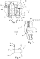
- the structure of the axial bearing 36 is based on the Fig. 2 to recognize.
- the two coils 46 are each arranged in a coil housing 48 which is approximately U-shaped when viewed in cross section.
- the bearing ring 50 penetrates into the space between the two coils 46.
- a distance a is formed between the bearing ring 50 and a respective coil 46.
- the coil housings 48 also seal the space between them in the radial direction.
- an intermediate piece 84 is arranged for this purpose, which is designed as a ring that adjoins the bearing ring 50 on the circumferential side.
- the intermediate piece 84 is arranged between the two coil housings 48 and sealed with sealing elements, especially O-rings 70.
- the left bobbin case 48 is still Sealed by an O-ring 70 to a further housing part of the generator housing 32.
- the axial position sensor 52a detects an axial distance value from the axial measuring ring 54a. This distance value is directly correlated to the distance a between the two coils 46 and the bearing ring 50.Based on the geometric relationships, the measured distance value can be clearly converted into the distance a between the turbine-side coil 46 and the bearing ring 50 on the one hand and the generator-side coil on the other to the bearing ring 50 assumes.
- the two distances can also differ. In the normal operating state, the distance is typically set such that the distance a to the two coils 46 is identical.
- a sealing element is arranged between the turbine wheel 16 and the annular flange 12 and has annular webs protruding in the axial direction. These annular webs engage in corresponding annular grooves on the back of the turbine wheel 16 and form the aforementioned labyrinth seal 24.
- the annular webs and the annular grooves are only arranged in the outermost circumferential area of the turbine wheel 16.
- a further gap 86 with a gap dimension s is formed between the turbine wheel 16 and the generator housing 32, that is to say specifically the annular flange 12.
- the sealing effect of the labyrinth seal 24 is defined by a gap, not shown here, between the annular webs and the annular grooves. This varies with a change in the gap dimension s of the gap 86, that is to say it is correlated with the gap dimension s.
- the turbine generator 2 is assigned a control device 90 which is preferably a direct component of the turbine generator 2.
- a control device 90 On the turbine part 8 there is a supply line 92 on the inlet side and a discharge line 94 on the outlet side for the Medium M connected.
- An example is in the Fig. 4 a flow valve 96 is arranged in the supply line 92.
- such a device can be arranged in addition or as an alternative in the discharge line 94.
- a pressure is formed on the rear side of the turbine wheel 16 on the generator side and a differential pressure ratio is established between the front side on the turbine side and this rear side of the turbine wheel 16.
- Different pressures lead to an axial force acting on the turbine wheel 16 and the generator shaft 14.
- the sealing arrangement 24 is preferably designed in such a way that the pressure conditions in normal operation on the front side and rear side are the same or as similar as possible, so that no differential pressure or, if possible, no differential pressure develops. As a result, no axial force or, if possible, no axial force is generated, and the axial bearing 36 does not have to absorb any or only small axial forces.
- varying process parameters such as varying speeds, varying pressure ratios, varying flow rates, varying temperatures, etc. can result in the gap dimension s between the turbine wheel 16 and the annular flange 12 varying.
- Varying process parameters i.e. unsteady operating states, occur, for example, when starting up. This can lead to a slight bending of the turbine wheel 16, which has a direct influence on the gap dimension s and the sealing effect of the labyrinth seal 24.
- the leakage current flowing through the further gap 86 changes, which leads to a change in the pressure conditions and especially the pressure difference between the front and the rear of the turbine wheel 16 and ultimately to an axial force resulting on the generator shaft 14.
- a regulation is first integrated in the control device 90, which controls the coil currents of the two coils 46 accordingly in order to set the distance a between the respective coils 46 and the bearing ring 50 to a desired predetermined setpoint. This is preferably selected such that the bearing ring 50 is arranged exactly in the middle between the coils 46.
- the control device 90 first switches from a normal operating mode to the optimized operating mode if, for example, a difference in the coil currents of the coils 46 of the axial bearing 36 is greater than 20% or greater than 30% of an average value of the coil currents of the two coils 46. If this measure is not sufficient, the safety mode is preferably initiated when a special safety-critical operating situation is reached.
- control device switches to the safety mode and emits the control signal S when one of the two coil currents of the two coils 46 exceeds a predetermined threshold, also referred to as the current threshold, of, for example, 75% of a maximum permissible coil current.
- a predetermined threshold also referred to as the current threshold
- the target value for the distance a is changed.
- an axial force is deliberately generated by changing the coil currents, so that the bearing ring 50 and thus the entire generator shaft 14 is displaced in or against the axial direction 6 relative to the stationary part 28.
- the change in the setpoint value for the distance a is such that - depending on the current operating situation - the gap dimension s is increased or decreased, specifically in such a way that the coil currents of the two coils 46 are equal.
- the new setpoint value a is set in such a way that the gap dimension s is reduced again. That is, the bearing ring 50 is deliberately offset in the axial direction 6 relative to the turbine part 8 by the axial bearing.
- This measure therefore directly influences the sealing effect of the labyrinth seal 24 via the variation of the setpoint value for the distance a, preferably in the direction of a bearing that is as free from axial forces as possible, or it is regulated to a maximum efficiency of the turbine generator 2.
- the control device 90 emits a control signal S with which the flow valve 96 is activated, for example, in order to reduce the mass flow for the medium M, for example.
- the speed of the turbine generator 2 is limited by the control.
- both variants are used, in particular, in combination, the setpoint value being varied initially - when the first triggering criterion is reached. Since this can only be varied within a limited range, since a distance must remain between the coils and the bearing ring 50, the additional measure according to the second variant may be necessary in unfavorable situations. This is therefore additionally initiated in particular when the setpoint has already reached a maximum permissible value and the second triggering criterion, namely the exceeding of the current threshold for the coil current, is also exceeded.
Description
Die Erfindung betrifft einen klein bauenden Turbinengenerator mit den Merkmalen des Oberbegriffs des Anspruchs 1. Die Erfindung betrifft weiterhin ein Verfahren zum Betrieb eines solchen klein bauenden Turbinengenerators mit den Merkmalen des Oberbegriffs des Anspruchs 11.The invention relates to a small turbine generator with the features of the preamble of claim 1. The invention also relates to a method for operating such a small turbine generator with the features of the preamble of claim 11.
Ein derartiger Turbinengenerator ist beispielsweise in der
Der Turbinengenerator dient zur Gewinnung von elektrischer Energie, speziell zur Energie(rück)gewinnung aus einem Medium, beispielsweise bei industriellen Prozessen. Der Turbinengenerator ist eine Baueinheit aus einer Entspannungsturbine, nachfolgend allgemein als Turbinenteil bezeichnet und einem Generator, nachfolgend allgemein als Generatorteil bezeichnet. Zur Gewinnung von Energie wird allgemein ein gasförmiges Medium durch den Turbinenteil geleitet und dadurch der Generatorteil zur Erzeugung von elektrischer Energie angetrieben. Es ist eine direkte Nutzung möglich, bei der unmittelbar ein Druckgefälle im Medium ausgenutzt wird. Daneben besteht auch die Möglichkeit einer indirekten Nutzung, bei der ein derartiger Turbinengenerator beispielsweise zur Energierückgewinnung aus Abwärme in einem geschlossenen Kreislaufprozess, beispielsweise in einem sogenannten ORC-Prozess (Organic Rankine Cycle) eingesetzt wird. Ein Anwendungsgebiet hierfür ist beispielsweise die Energierückgewinnung aus Abgas in einem Kraftfahrzeug, wie sie in der
Die Turbinengeneratoren sind vergleichsweise klein bauend und für elektrische Leistungen von - je nach Anwendungsfall - größer oder gleich 30 kW bis maximal 300 kW ausgebildet. Der Durchmesser eines Turbinenrads des Turbinenteils liegt - je nach Anwendungsfall - über 50mm und unter 500 mm und insbesondere unter 400 mm. Die Gesamtlänge des Turbinengenerators, also die Länge in Axialrichtung des Turbinenteils zuzüglich der Länge des Generatorteils, liegt im Bereich zwischen 350mm und 1500mm.The turbine generators are comparatively small and designed for electrical outputs of - depending on the application - greater than or equal to 30 kW up to a maximum of 300 kW. The diameter of a turbine wheel of the turbine part is - depending on the application - more than 50 mm and less than 500 mm and in particular less than 400 mm. The total length of the turbine generator, that is to say the length in the axial direction of the turbine part plus the length of the generator part, is in the range between 350 mm and 1500 mm.
Je nach Anwendungsfall werden kleine Turbinengeneratoren eingesetzt, deren elektrische Leistung lediglich im Bereich von 30 kW bis 200 kW liegen und bei denen das Turbinenrad entsprechend einen kleineren Durchmesser, beispielsweise zwischen 50 bis 400 mm aufweist. Je nach Anwendungsgebiet liegen die ausnutzbaren Druckdifferenzen des Mediums unter 1 bar, beginnen beispielsweise bei 0,2 bar und reichen bis maximal mehrere 10 bar, beispielsweise bis maximal 100 bar. Weiterhin liegen die Temperaturen der gasförmigen Medien, aus denen die Energie gewonnen wird, je nach Anwendungsgebiet in einem Bereich zwischen minus 50° und 400°C, typischerweise im Bereich zwischen 0° und 250°C.Depending on the application, small turbine generators are used whose electrical power is only in the range from 30 kW to 200 kW and in which the turbine wheel has a correspondingly smaller diameter, for example between 50 to 400 mm. Depending on the area of application, the usable pressure differences of the medium are below 1 bar, starting, for example, at 0.2 bar and extending up to a maximum of several 10 bar, for example up to a maximum of 100 bar. Furthermore, the temperatures of the gaseous media from which the energy is obtained are in a range between
Der Turbinengenerator zeichnet sich im Betrieb durch eine sehr hohe Drehzahl aus. Die Drehzahlen im Betrieb liegen dabei typischerweise über 4.000 U/min. Insbesondere liegt eine Betriebsdrehzahl, also eine Drehzahl, für die der Turbinengenerator ausgelegt ist und die im Betrieb auch erreicht wird, im Bereich zwischen 8.000 bis 40.000 U/min.The turbine generator is characterized by a very high speed in operation. The speeds during operation are typically over 4,000 rpm. In particular, an operating speed, that is to say a speed for which the turbine generator is designed and which is also achieved during operation, is in the range between 8,000 and 40,000 rpm.
Für das durch den Turbinenteil strömende Medium werden in Abhängigkeit des speziellen Anwendungsgebiets unterschiedliche, teilweise auch aggressive Medien und beispielsweise auch Kältemittel eingesetzt.For the medium flowing through the turbine part, different, sometimes aggressive media and, for example, also refrigerants, are used depending on the specific area of application.
Der Turbinenteil und der Generatorteil erstrecken sich entlang einer gemeinsamen Längsachse und sind typischerweise über eine gemeinsame Generatorwelle miteinander verbunden. Zwischen einem im Betrieb rotierenden Turbinenrad des Turbinenteils und einem feststehenden Gehäuseteil ist eine üblicherweise als Labyrinthdichtung ausgebildete Dichtanordnung angeordnet. Über Leckströme kann das den Turbinenteil durchströmende Medium in einen Innenraum des Generatorteils eindringen. Dies führt zum einen dazu, dass Bauteile des Generatorteils dem Medium ausgesetzt sind.The turbine part and the generator part extend along a common longitudinal axis and are typically connected to one another via a common generator shaft connected. A sealing arrangement, usually designed as a labyrinth seal, is arranged between a turbine wheel of the turbine part that rotates during operation and a stationary housing part. The medium flowing through the turbine part can penetrate into an interior of the generator part via leakage currents. On the one hand, this leads to components of the generator part being exposed to the medium.
Weiterhin führt dies auch dazu, dass sich im Generatorteil ein Druck einstellt, welcher zwischen dem Druck an einem Einlass für das Medium und dem Druck an einem Auslass für das Medium des Turbinenteils liegt. Die Generatorwelle ist typischerweise mithilfe eines Axiallagers sowie mithilfe zweier Radiallager gelagert. Variierende Betriebszustände können zu einer Veränderung eines Druckunterschieds zwischen einer Vorderseite des Turbinenrads und einer zum Generatorteil orientierten Rückseite des Turbinenrads führen, wodurch eine variierende Axialkraft erzeugt wird. Die Axialkraft wird von dem Axiallager abgefangen.Furthermore, this also means that a pressure is established in the generator part which is between the pressure at an inlet for the medium and the pressure at an outlet for the medium of the turbine part. The generator shaft is typically supported with the help of a thrust bearing and two radial bearings. Varying operating states can lead to a change in a pressure difference between a front side of the turbine wheel and a rear side of the turbine wheel oriented towards the generator part, as a result of which a varying axial force is generated. The axial force is absorbed by the axial bearing.
Aus der
In der
Ausgehend hiervon liegt der Erfindung die Aufgabe zugrunde, einen zuverlässigen Betrieb eines Turbinengenerators auch bei variierenden Betriebszuständen zu ermöglichen.Proceeding from this, the invention is based on the object of enabling reliable operation of a turbine generator even with varying operating conditions.
Die Aufgabe wird gemäß der Erfindung gelöst durch einen kleinbauenden Turbinengenerator mit den Merkmalen des Anspruchs 1 sowie durch ein Verfahren zum Betrieb eines kleinbauenden Turbinengenerators mit den Merkmalen des Anspruchs 11. Die nachfolgend im Hinblick auf den Turbinengenerator angeführten Vorteile und bevorzugten Ausgestaltungen sind sinngemäß auch auf das Verfahren zu übertragen.The object is achieved according to the invention by a compact turbine generator with the features of claim 1 and by a method for operating a compact turbine generator with the features of claim 11. The advantages and preferred embodiments cited below with regard to the turbine generator are analogously also to the Transfer procedure.
Der Turbinengenerator ist ausgelegt für Drehzahlen von größer 4.000 U/min. Er weist dabei die Abmessungen und Kenngrößen auf, wie sie eingangs in der Beschreibungseinleitung angegeben sind und ist auch für die dort beschriebenen Einsatzzwecke ausgelegt und wird dort eingesetzt. Speziell ist der Turbinengenerator für eine Betriebsdrehzahl im Bereich zwischen 8 000 und 40 000 U/min ausgelegt und wird im Betrieb auch bei derartigen Drehzahlen betrieben. Weiterhin weist ein Turbinenteil einen Durchmesser vorzugsweise im Bereich zwischen 50 mm und 500 mm auf.The turbine generator is designed for speeds of more than 4,000 rpm. It has the dimensions and parameters as specified in the introduction to the description and is also designed for the purposes described there and is used there. The turbine generator is specially designed for an operating speed in the range between 8,000 and 40,000 rpm and is also operated at such speeds during operation. Farther a turbine part has a diameter preferably in the range between 50 mm and 500 mm.
Der Turbinengenerator weist den Turbinenteil sowie einen Generatorteil auf, die sich entlang einer Rotationsachse in einer Axialrichtung vom Turbinenteil zum Generatorteil erstrecken. Der Generatorteil weist einen rotierenden Teil sowie einen feststehenden Teil auf. Der Turbinenteil weist ein Turbinenrad sowie einen Einlass und einen Auslass für ein Medium auf, welches im Betrieb durch das Turbinenrad strömt. Der Turbinenteil ist bevorzugt als Radialturbine mit einem radialen Einlass und einem axialen Auslass ausgebildet oder alternativ als Axialturbine, bei dem sowohl der Einlass als auch der Auslass axial orientiert sind. Zwischen dem Turbinenteil und einem feststehenden (Gehäuse-)Teil -je nach Ausgestaltung entweder ein Gehäuseteil des Turbinenteils (z.B. bei einer Axialturbine) oder ein Gehäuseteil des Generatorteils (z.B. bei einer Radialturbine) ist eine Dichtanordnung vorgesehen, die im Betrieb das rotierende Turbinenrad gegenüber dem feststehenden Teil abdichtet. Prinzip- und bauartbedingt strömt ein Teil des Mediums im Betrieb über die Dichtanordnung als Leckstrom hinweg und dringt beispielsweise in einen Innenraum des Generatorteils ein. Je nach Betriebssituation kann dabei die Dichtwirkung der Dichtanordnung im Betrieb variieren. Der Generatorteil weist weiterhin eine Generatorwelle auf, die zumindest einen Lagerring umfasst. Dieser ist vorzugsweise als separates Bauteil mit der Generatorwelle verbunden. Die Generatorwelle erstreckt sich bis in den Turbinenteil und das Turbinenrad ist auf der Generatorwelle befestigt. Die Generatorwelle ist über ein als Magnetlager ausgebildetes Axiallager sowie typischerweise über mehrere Radiallager gelagert. Das Axiallager kann an unterschiedlichen Positionen entlang der Generatorwelle angeordnet sein. Es ist vorzugsweise im Generatorteil angeordnet und dort insbesondere unmittelbar anschließend an den Turbinenteil. Alternativ ist es zwischen einem ersten Radiallager und einem Rotor oder am Ende des Generatorteils nach dem Rotor angeordnet.The turbine generator has the turbine part and a generator part, which extend along an axis of rotation in an axial direction from the turbine part to the generator part. The generator part has a rotating part and a stationary part. The turbine part has a turbine wheel and an inlet and an outlet for a medium which flows through the turbine wheel during operation. The turbine part is preferably designed as a radial turbine with a radial inlet and an axial outlet or, alternatively, as an axial turbine in which both the inlet and the outlet are axially oriented. Between the turbine part and a stationary (housing) part - depending on the design, either a housing part of the turbine part (e.g. in the case of an axial turbine) or a housing part of the generator part (e.g. in the case of a radial turbine), a sealing arrangement is provided which, when in operation, the rotating turbine wheel opposite the fixed part seals. Due to the principle and design, part of the medium flows over the sealing arrangement as a leakage current during operation and penetrates, for example, into an interior of the generator part. Depending on the operating situation, the sealing effect of the sealing arrangement can vary during operation. The generator part also has a generator shaft which comprises at least one bearing ring. This is preferably connected to the generator shaft as a separate component. The generator shaft extends into the turbine part and the turbine wheel is attached to the generator shaft. The generator shaft is supported by an axial bearing designed as a magnetic bearing and typically by several radial bearings. The axial bearing can be arranged at different positions along the generator shaft. It is preferably arranged in the generator part and there in particular directly adjoining the turbine part. Alternatively, it is arranged between a first radial bearing and a rotor or at the end of the generator part after the rotor.
Das Axiallager weist allgemein zwei zueinander beabstandete Spulen auf, nämlich eine dem Generatorteil zugewandte und eine dem Generatorteil abgewandte (turbinenseitige) Spule. In Axialrichtung betrachtet weist das Axiallager daher eine vordere (turbinenseitige) und eine hintere (generatorseitige) Spule auf. Zwischen den Spulen ist der zumindest eine Lagerring mit einem jeweiligen axialen Abstand zu den Spulen angeordnet.The axial bearing generally has two coils spaced apart from one another, namely one coil facing the generator part and one coil facing away from the generator part (turbine-side). Viewed in the axial direction, the axial bearing therefore has a front (turbine-side) and a rear (generator-side) coil. The at least one bearing ring is arranged between the coils at a respective axial distance from the coils.
Gemäß einer bevorzugten Variante sind die beiden Spulen genau einem (einzigen) Lagerring zugeordnet und beidseitig unmittelbar, also insbesondere ohne Zwischenschaltung von weiteren Komponenten, zu diesem einen Lagerring mit dem jeweiligen Abstand angeordnet.According to a preferred variant, the two coils are assigned to exactly one (single) bearing ring and are arranged directly on both sides, that is to say in particular without the interposition of further components, to this one bearing ring with the respective spacing.
Alternativ besteht auch die Möglichkeit, dass zwei voneinander in Axialrichtung beabstandete Lagerringe ausgebildet sind. In Axialrichtung betrachtet sind daher eine vorderer, turbinenseitiger sowie ein hinterer, generatorseitiger Lagerring vorgesehen. Zwischen den beiden Lagerringen ist beispielsweise ein Stator / Rotor des Generators angeordnet. Jede der Spulen ist dabei genau einem Lagerring zugeordnet, wobei die eine Spule in Axialrichtung vor und die andere Spule in Axialrichtung nach dem ihr zugeordneten Lagerring angeordnet ist. Bevorzugt ist die vordere Spule in Axialrichtung vor dem vorderen Lagerring und die hintere Spule in Axialrichtung hinter dem hinteren Lagerring angeordnet. Das Axiallager ist bei dieser alternativen Ausgestaltung daher nach Art eines geteilten Axiallagers ausgebildet, bei dem die beiden Spulen des Axiallagers den beiden voneinander beabstandeten Lagerringen zugeordnet sind.Alternatively, there is also the possibility that two bearing rings spaced apart from one another in the axial direction are formed. Viewed in the axial direction, a front, turbine-side and a rear, generator-side bearing ring are therefore provided. A stator / rotor of the generator, for example, is arranged between the two bearing rings. Each of the coils is assigned to exactly one bearing ring, one coil being arranged in the axial direction in front of and the other coil in the axial direction after the bearing ring assigned to it. The front coil is preferably arranged in the axial direction in front of the front bearing ring and the rear coil in the axial direction behind the rear bearing ring. In this alternative embodiment, the axial bearing is therefore designed in the manner of a split axial bearing, in which the two coils of the axial bearing are assigned to the two spaced-apart bearing rings.
Nachfolgend wird die Erfindung ohne Beschränkung der Allgemeinheit im Zusammenhang mit dem Axiallager mit dem einen Lagerring und den beidseitig angeordneten Spulen beschrieben. Die Ausführungen gelten gleichermaßen auch für die alternative Variante eines geteilten Axiallagers.The invention is described below, without restricting the generality, in connection with the axial bearing with the one bearing ring and the coils arranged on both sides. The explanations apply equally to the alternative variant of a split axial bearing.
Für den Betrieb des Turbinengenerators allgemein und speziell auch zum Steuern des Axiallagers ist eine Steuereinrichtung angeordnet. Diese ist derart ausgebildet, dass der axiale Abstand zwischen dem zumindest einen Lagerring und zumindest einer der Spulen auf einen Sollwert geregelt wird. Die Regelung des Abstands zwischen dem zumindest einen Lagerring und der anderen Spule ergibt sich typischerweise automatisch durch die konstruktive, mechanische feste Zuordnung zwischen den einzelnen Lagerringen und den Spulen.A control device is arranged for the operation of the turbine generator in general and specifically also for controlling the axial bearing. This is designed such that the axial distance between the at least one bearing ring and at least one of the coils is regulated to a target value. The regulation of the distance between the at least one bearing ring and the other coil results typically automatically through the structural, mechanical fixed assignment between the individual bearing rings and the coils.
Zu diesem Zweck ist die Steuereinrichtung dazu eingerichtet, im Betrieb die Spulen mit einem Spulenstrom zu beaufschlagen. Die Spulen sind für einen maximalen Spulenstrom ausgelegt. Um einen zuverlässigen Betrieb zu gewährleisten ist die Steuereinrichtung weiterhin zur Durchführung zumindest einer und vorzugsweise beider der nachfolgend angeführten Maßnahmen ausgebildet:
Gemäß einer ersten Variante wird in Abhängigkeit des aktuellen Betriebszustands, also bei Bedarf, wenn ein bestimmter Betriebszustand auftritt, der Sollwert variiert, auf den der axiale Abstand zwischen Lagerring und Spulen geregelt wird. Durch die Variation des Sollwerts wird das Ziel erreicht, die Dichtwirkung der Dichtanordnung und damit die am Turbinenrad wirkenden Axialkräfte zu beeinflussen.For this purpose, the control device is set up to apply a coil current to the coils during operation. The coils are designed for a maximum coil current. In order to ensure reliable operation, the control device is also designed to carry out at least one and preferably both of the measures listed below:
According to a first variant, the setpoint to which the axial distance between the bearing ring and the coils is regulated is varied as a function of the current operating state, that is to say if necessary when a certain operating state occurs. By varying the setpoint, the aim of influencing the sealing effect of the sealing arrangement and thus the axial forces acting on the turbine wheel is achieved.
Gemäß der zweiten Variante wird bei der Erfassung einer Überschreitung einer Stromschwelle für den Spulenstrom zumindest einer der beiden Spulen ein Steuersignal zum Steuern der Strömung des Mediums oder der Drehzahl des Turbinengenerators abgegeben. Bei dieser Maßnahme werden die Axialkräfte durch Steuereingriffe auf Seiten des Mediums oder durch eine Begrenzung der Drehzahl beeinflusst.According to the second variant, when a current threshold is detected for the coil current at least one of the two coils, a control signal for controlling the flow of the medium or the speed of the turbine generator is emitted. With this measure, the axial forces are influenced by control interventions on the part of the medium or by limiting the speed.
Die beiden Maßnahmen dienen der Verbesserung eines zuverlässigen und sicheren Betriebs des Turbinengenerators. Sie beruhen auf der Erkenntnis, dass die Dichtwirkung der Dichtanordnung im Betrieb variiert, was zu einer Veränderung einer Druckdifferenz zwischen einer Vorderseite des Turbinenrads und einer Rückseite des Turbinenrads führt. Die Rückseite des Turbinenrads ist dabei zum Generatorteil hin orientiert. Die Dichtanordnung ist üblicherweise derart ausgelegt, dass im Betrieb sich auf der Vorderseite und der Rückseite des Turbinenrads ein wirksamer gleicher Druck einstellt, sodass die Generatorwelle im Betrieb axiallastfrei oder zumindest weitgehend axiallastfrei gelagert ist.The two measures serve to improve reliable and safe operation of the turbine generator. They are based on the knowledge that the sealing effect of the sealing arrangement varies during operation, which leads to a change in a pressure difference between a front side of the turbine wheel and a rear side of the turbine wheel. The back of the turbine wheel is oriented towards the generator part. The sealing arrangement is usually designed in such a way that, during operation, an effective equal pressure is established on the front side and the rear side of the turbine wheel, so that the generator shaft is supported free of axial load or at least largely free of axial load during operation.
Von dem Axiallager und den Spulen ist daher im Idealfall keine nennenswerte Axialkraft auf den Lagerring auszuüben, um diesen in einer gewünschten Position zu halten. Variierende Betriebszustände, wie Drehzahl, Massenstrom, Temperatur und Druck, führen jedoch - speziell bei Lastwechseln, wie beispielsweise beim Anfahren oder Herunterfahren des Turbinengenerators - zu Veränderungen in der Geometrie des Turbinenrads und der Dichtanordnung, sodass deren Dichtwirkung variiert. Durch die Variation der Dichtwirkung erhöht oder erniedrigt sich der Leckstrom und damit auch der Druck auf der Rückseite. Dies hat unmittelbaren Einfluss auf den zwischen der Vorderseite und der Rückseite des Turbinenrads herrschenden wirksamen Differenzdruck. Dadurch wird eine Veränderung der auf das Turbinenrad und damit der auf die Generatorwelle wirkenden Axialkraft hervorgerufen, welche von dem Axiallager abgefangen werden muss.In the ideal case, therefore, no significant axial force needs to be exerted on the bearing ring by the axial bearing and the coils in order to hold it in a desired position. Varying operating conditions, such as speed, mass flow, temperature and pressure, however, lead to changes in the geometry of the turbine wheel and the sealing arrangement - especially in the event of load changes, such as when starting up or shutting down the turbine generator, so that their sealing effect varies. The variation in the sealing effect increases or decreases the leakage current and thus also the pressure on the rear side. This has a direct influence on the effective differential pressure prevailing between the front and the rear of the turbine wheel. This causes a change in the axial force acting on the turbine wheel and thus in the axial force acting on the generator shaft, which must be absorbed by the axial bearing.
Durch die Regelung des Axiallagers auf den gewünschten Sollwert, der für normale Betriebszustände üblicherweise fest vorgegeben ist, wird die sich verändernde Axialkraft über das Axiallager abgefangen. Hierzu werden die Spulenströme geeignet eingestellt, sodass die beiden in Axialrichtung versetzten Teile des Axiallagers mit unterschiedlichen Spulenströmen beaufschlagt werden, sodass die Lagerteile unterschiedliche Axialkräfte auf den Lagerring und damit die Generatorwelle ausüben.By regulating the axial bearing to the desired setpoint, which is usually fixed for normal operating conditions, the changing axial force is intercepted via the axial bearing. For this purpose, the coil currents are suitably set so that the two parts of the axial bearing offset in the axial direction are acted upon by different coil currents, so that the bearing parts exert different axial forces on the bearing ring and thus the generator shaft.
Werden jedoch die aufgrund der variierenden Dichtwirkung turbinenseitig auf die Generatorwelle ausgeübten Axialkräfte zu groß, nähert sich der Spulenstrom dem maximalen Spulenstrom an und es wird ein kritischer Betriebszustand erreicht. Über eine weitere Regelung des Axiallagers auf den vorgegebenen Sollwert kann dann unter Umständen eine ordnungsgemäße Lagerung nicht mehr sichergestellt sein und es kann zum Ausfall und Schaden des Lagers kommen.However, if the axial forces exerted on the generator shaft on the turbine side due to the varying sealing effect are too great, the coil current approaches the maximum coil current and a critical operating state is reached. A further regulation of the axial bearing to the specified target value can then possibly no longer ensure proper storage and the bearing can fail and be damaged.
Durch die beiden beschriebenen Maßnahmen wird ein derartiger kritischer Betriebszustand vermieden oder zumindest sichergestellt, dass der Turbinengenerator in einen sicheren Zustand überführt wird. Für die beiden Maßnahmen werden dabei vorzugsweise unterschiedliche Auslösekriterien herangezogen. Bevorzugt wird zunächst die erste Variante mit der Veränderung des Sollwerts durchgeführt und erst im Falle eines kritischen Zustands wird die zweite Variante umgesetzt. Vorliegend wird insbesondere unterschieden zwischen einem normalen Betriebsmodus, einem optimierten Betriebs-modus und einem Sicherheits-Modus.The two measures described prevent such a critical operating state or at least ensure that the turbine generator is transferred to a safe state. Different trigger criteria are preferably used for the two measures. Preferred the first variant is carried out with the change in the setpoint value and the second variant is only implemented in the event of a critical state. In the present case, a distinction is made in particular between a normal operating mode, an optimized operating mode and a safety mode.
Im normalen Betriebsmodus wird das Axiallager auf einen z.B. herstellerseitig vorgegebenen Normal-Sollwert für den Abstand geregelt oder alternativ wird der Turbinengenerator auf einen maximalen Wirkungsgrad geregelt, wobei Änderungen des Abstands in einem vorgegebenen Bereich vorzugsweise zulässig sind.In the normal operating mode, the axial bearing is regulated to a standard setpoint value for the distance specified by the manufacturer, for example, or, alternatively, the turbine generator is regulated to a maximum efficiency, with changes in the distance in a specified range preferably being permissible.
Im optimierten Betriebsmodus wird die Maßnahme gemäß der ersten Variante durchgeführt und der Sollwert für den Abstand verändert. Hierzu ist vorzugsweise ein erstes Auslösekriterium vorgesehen.In the optimized operating mode, the measure according to the first variant is carried out and the setpoint value for the distance is changed. A first trigger criterion is preferably provided for this purpose.
Im Sicherheits-Modus wird die Maßnahme gemäß der zweiten Variante durchgeführt. Der Sicherheits-Modus wird eingeleitet, wenn einer der Spulenströme den vorgegebenen Stromschwellwert überschreitet.In the safety mode, the measure is carried out according to the second variant. The safety mode is initiated when one of the coil currents exceeds the specified current threshold value.
Im Sicherheits-Modus ist zumindest eine der beiden Varianten vorgesehen. Insbesondere wenn beide Varianten vorgesehen sind und ausgeführt werden, sind vorzugsweise unterschiedliche Stromschwellwerte vorgesehen, und zwar ein niedriger, erster Stromschwellwert für die Einleitung der ersten Variante (Veränderung des Sollwertes) und ein höherer, zweiter Stromschwellwert für die Einleitung der zweiten Variante (Veränderung der Strömungsverhältnisse des Mediums). Anstelle von absoluten Stromschwellwerten der Spulenströme werden alternativ mit den Spulenströmen korrelierte Größen, beispielsweise relative oder absolute Differenzwerte zwischen den Spulenströmen oder auch absolute oder relative Abstandsmaße als (Strom) Schwellwerte für die Einleitung der Maßnahmen herangezogen.At least one of the two variants is provided in safety mode. In particular, if both variants are provided and implemented, different current threshold values are preferably provided, namely a lower, first current threshold value for the introduction of the first variant (change in the setpoint value) and a higher, second current threshold value for the introduction of the second variant (change in the flow conditions of the medium). Instead of absolute current threshold values of the coil currents, quantities correlated with the coil currents, for example relative or absolute difference values between the coil currents or also absolute or relative distance measurements, are used as (current) threshold values for initiating the measures.
Sowohl aus dem optimierten Modus als auch aus dem Sicherheits-Modus wird vorzugsweise wieder in den normalen Betriebsmodus übergegangen, wenn die Betriebsparameter dies zulassen, wenn z.B. der Turbinengenerator nach einem Anfahren in einen quasi stationären Betriebszustand übergeht. Bei der ersten Variante geschieht der Übergang aus dem optimierten Modus in den normalen Betriebsmodus vorzugsweise automatisch, wenn nämlich - z.B. nach Erreichen des stationären Betriebszustands - der Sollwert automatisch wieder in Richtung zum vorgegebenen Sollwert verändert wird.Both the optimized mode and the safety mode are preferably switched back to the normal operating mode if the operating parameters allow this, for example if the turbine generator after a Start-up changes to a quasi-steady-state operating state. In the first variant, the transition from the optimized mode to the normal operating mode preferably takes place automatically, namely when - for example, after the steady-state operating state has been reached - the setpoint value is automatically changed again in the direction of the predetermined setpoint value.
Die zweitgenannte Variante greift in einem kritischen Betriebszustand in eine Drehzahlregelung des Turbinengenerators oder in eine Steuerung der Strömungsverhältnisse des Mediums ein, sodass sich die Betriebsparameter, wie beispielsweise Massenstrom, Druck, Drehzahl, Temperatur, verändern und insbesondere reduziert werden, um also den Turbinengenerator wieder in einen sicheren Betriebszustand zu überführen.In a critical operating state, the second variant intervenes in a speed control of the turbine generator or in a control of the flow conditions of the medium, so that the operating parameters, such as mass flow, pressure, speed, temperature, change and, in particular, are reduced so that the turbine generator can be switched back on to transfer a safe operating state.
Die erstgenannte Variante setzt demgegenüber an der Erkenntnis an, dass die Dichtwirkung der Dichtanordnung maßgebend von dem Abstand und dem Spaltmaß zwischen dem Turbinenrad und dem stehenden Gehäuseteil, insbesondere dem feststehenden Teil des Generatorteils, im Bereich der Dichtanordnung abhängt.In contrast, the first-mentioned variant is based on the knowledge that the sealing effect of the sealing arrangement depends largely on the distance and the gap between the turbine wheel and the stationary housing part, in particular the stationary part of the generator part, in the area of the sealing arrangement.
Dieses Spaltmaß wird also bevorzugt bewusst variiert, und zwar durch eine Variation des Sollwerts für das Axiallager. Durch diese Maßnahme wird daher quasi aktiv über die von dem Axiallager ausgeübten Axialkräfte der Lagerring und mit ihm die Generatorwelle relativ zum feststehenden Teil des Generatorteils axial verschoben. Dadurch wird unmittelbar das Spaltmaß zwischen Turbinenrad und dem feststehenden Teil und damit die Dichtwirkung beeinflusst.This gap dimension is therefore preferably varied deliberately, namely by varying the setpoint value for the axial bearing. As a result of this measure, the bearing ring, and with it the generator shaft, is moved axially relative to the stationary part of the generator part, as it were, via the axial forces exerted by the axial bearing. This directly influences the size of the gap between the turbine wheel and the stationary part and thus the sealing effect.
Die Variation des Sollwerts wird dabei vorzugsweise derart gewählt, dass die Dichtwirkung derart verändert wird, dass eine Angleichung der Druckverhältnisse auf der Vorderseite und der Rückseite des Turbinenrads erzielt wird, um die gewünschte axialkraftfreie oder zumindest weitgehend axialkraftfreie Lagerung der Generatorwelle zu erzielen.The variation of the setpoint is preferably selected in such a way that the sealing effect is changed in such a way that an equalization of the pressure conditions on the front and rear of the turbine wheel is achieved in order to achieve the desired axial force-free or at least largely axial-force-free mounting of the generator shaft.
Gemäß einer bevorzugten Weiterbildung wird der Sollwert dabei derart variiert, dass eine Angleichung der von den beiden Spulen erzeugten Axialkräfte bewirkt wird.According to a preferred development, the setpoint is varied in such a way that the axial forces generated by the two coils are matched.
Der Sollwert wird weiterhin vorzugsweise in einem maximal zulässigen Arbeitsbereich variiert, der im Bereich von ± 0,5mm liegt. Das heißt, die maximal zulässige Änderung des für den Sollwert maßgebenden Abstandswerts zwischen Lagerring und jeweiliger Spule liegt in diesem Arbeitsbereich.The nominal value is furthermore preferably varied in a maximum permissible working range which is in the range of ± 0.5 mm. This means that the maximum permissible change in the distance value between the bearing ring and the respective coil, which is decisive for the setpoint value, lies in this working range.
In bevorzugter Weiterbildung wird der durch die Variation des Sollwerts durchgeführte optimierte Betriebsmodus dann eingeleitet, wenn - als Auslösekriterium - eine Differenz zwischen den Spulenströmen der beiden Spulen des Axiallagers und/oder ein Absolut-Wert dieser Spulenströme oder eine damit verbundene Größe eine vorgegebene Schwelle überschreitet.In a preferred development, the optimized operating mode carried out by varying the setpoint value is initiated when - as a triggering criterion - a difference between the coil currents of the two coils of the axial bearing and / or an absolute value of these coil currents or an associated variable exceeds a predetermined threshold.
Vorzugsweise wird der optimierte Betriebsmodus dann eingeleitet, wenn die Differenz zwischen den Spulenströmen größer 20% oder größer 30% des beispielsweise gemittelten Spulenstroms der beiden Spulen (Mittelwert der Spulenströme der beiden Spulen) ist. Insbesondere wird der optimierte Betriebsmodus eingeleitet, wenn die Differenz zwischen 20% und 60% des gemittelten Spulenstroms liegt.The optimized operating mode is preferably initiated when the difference between the coil currents is greater than 20% or greater than 30% of the, for example, averaged coil current of the two coils (mean value of the coil currents of the two coils). In particular, the optimized operating mode is initiated when the difference is between 20% and 60% of the averaged coil current.
Alternativ oder ergänzend wird als Auslösekriterium ein Absolutwert der Spulenströme verwendet, beispielsweise wenn der Spulenstrom einer der beiden Spulen größer 20%, größer 30% und vorzugsweise im Bereich zwischen 20% und 50% des maximal zulässigen Spulenstroms liegt.Alternatively or in addition, an absolute value of the coil currents is used as the trigger criterion, for example if the coil current of one of the two coils is greater than 20%, greater than 30% and preferably in the range between 20% and 50% of the maximum permissible coil current.
Beide Auslösekriterien sind ein Indiz für eine erhöhte von dem Axiallager abzufangende Axialkraft.Both trigger criteria are an indication of an increased axial force to be absorbed by the axial bearing.
Zweckdienlicherweise wird der Sicherheits-Modus initiiert und die zweite Variante eingeleitet, wenn zumindest einer der Spulenströme der beiden Spulen größer als 60% und insbesondere größer als 75% des maximal zulässigen Spulenstroms ist, d.h. die Stromschwelle als Auslösekriterium liegt in diesen Bereichen, vorzugsweise im Bereich zwischen 60% und 85% des maximal zulässigen Spulenstroms.The safety mode is expediently initiated and the second variant initiated when at least one of the coil currents of the two coils is greater than 60% and in particular greater than 75% of the maximum permissible coil current, ie the current threshold as a triggering criterion lies in these ranges, preferably in the range between 60% and 85% of the maximum permissible coil current.
Allgemein liegt die Auslöseschwelle für den Sicherheits-Modus höher als für den optimierten Modus.
Für die zweitgenannte Maßnahme, gemäß der bei Überschreiten der Stromschwelle ein Steuersignal abgegeben wird, wird zweckdienlicherweise eine oder es werden mehrere der nachfolgenden Maßnahmen veranlasst:
- Es wird der Massenstroms des Mediums verringert, speziell durch Ansteuern eines Strömungsventils für das Medium oder indem das Medium über einen Bypass an dem Turbinenteil vorbeigeführt wird,
- es wird die aktuelle Drehzahl beispielsweise auf einen vorgegebenen Wert begrenzt oder sie wird reduziert,
- die Druckverhältnisse am Einlass- und/oder Auslass des Turbinenrads werden verändert. Dies erfolgt wiederum vorzugsweise durch das Ansteuern von Klappen oder Ventilen, oder durch Veränderung von übergeordneten Prozessparametern eines vorgelagerten Betriebsprozesses, welcher Einfluss auf diese Druckverhältnisse nimmt.
For the second-mentioned measure, according to which a control signal is emitted when the current threshold is exceeded, one or more of the following measures are expediently initiated:
- The mass flow of the medium is reduced, especially by controlling a flow valve for the medium or by leading the medium past the turbine part via a bypass,
- the current speed is limited, for example, to a specified value or it is reduced,
- the pressure conditions at the inlet and / or outlet of the turbine wheel are changed. This in turn is preferably done by controlling flaps or valves, or by changing higher-level process parameters of an upstream operating process that influences these pressure conditions.
Die Dichtanordnung ist weiterhin vorzugsweise als eine Labyrinthdichtung ausgebildet. Bei dieser greifen vorzugsweise Ringstege eines Dichtelements in entsprechende Ringnuten an der Rückseite des Turbinenrads ein.The sealing arrangement is also preferably designed as a labyrinth seal. In this case, ring webs of a sealing element preferably engage in corresponding ring grooves on the rear side of the turbine wheel.
Zur Steuerung und Regelung des axialen Abstands ist allgemein eine Messeinrichtung vorgesehen, über die dieser axiale Abstand ermittelt wird. Speziell ist zumindest ein Abstandssensor angeordnet, der einen Referenzabstand zwischen einem rotierenden Teil und einem feststehenden Teil misst. Die Messung erfolgt vorzugsweise in axialer Richtung auf eine spezielle Messfläche, die beispielsweise durch einen an der Generatorwelle angebrachten Messring ausgebildet ist. Der Abstandssensor ist mit dem feststehenden Teil des Generatorteils verbunden. Der axiale Abstand zwischen der jeweiligen Spule des Axiallagers und dem Lagerring wird daher vorzugsweise indirekt und mittelbar über die Abstandsmessung dieser Messanordnung erfasst.To control and regulate the axial distance, a measuring device is generally provided, by means of which this axial distance is determined. In particular, at least one distance sensor is arranged which measures a reference distance between a rotating part and a stationary part. The measurement is preferably carried out in the axial direction on a special measuring surface, which is formed, for example, by a measuring ring attached to the generator shaft. The distance sensor is connected to the stationary part of the generator part. The axial distance between the respective coil of the axial bearing and the bearing ring is therefore preferably recorded indirectly and indirectly via the distance measurement of this measuring arrangement.
Eine Ausführungsvariante der Erfindung wird nachfolgend anhand der Figuren näher erläutert. Diese zeigen teilweise in vereinfachten Darstellungen:
- Fig. 1
- eine teilweise Längsschnittdarstellung durch einen Turbinengenerator,
- Fig. 2
- eine vergrößerte Schnittdarstellung des in
Fig. 1 mit dem Buchstaben C gekennzeichneten Axiallagerbereichs, - Fig. 3
- eine vergrößerte Darstellung des in der
Fig. 1 mit dem Buchstaben D gekennzeichneten Bereichs mit einer Labyrinthdichtung sowie - Fig. 4
- eine stark vereinfachte Prinzipdarstellung des Turbinengenerators mit Zu- und Ableitung für das Medium.
- Fig. 1
- a partial longitudinal section through a turbine generator,
- Fig. 2
- an enlarged sectional view of the in
Fig. 1 the axial bearing area marked with the letter C, - Fig. 3
- an enlarged view of the in the
Fig. 1 area marked with the letter D with a labyrinth seal as well - Fig. 4
- a greatly simplified schematic diagram of the turbine generator with inlet and outlet for the medium.
In den Figuren sind gleich wirkende Bauteile mit den gleichen Bezugszeichen versehen.In the figures, components that have the same effect are provided with the same reference symbols.
Ein in der
Der Turbinenteil 8 sowie der Generatorteil 10 weisen eine gemeinsame durchgehende Generatorwelle 14 auf. Auf dieser ist im Turbinenteil 8 ein Turbinenrad 16 befestigt, welches um den Umfang verteilt Schaufeln aufweist und zu einem Turbinengehäuse 18 Strömungskanäle einschließt. Im Betrieb wird ein Medium M über Einlass 20 zugeführt, durchströmt den Turbinenteil 8 und verlässt diesen über einen Auslass 22. Bei dem in der Figur dargestellten Turbinenteil 8 handelt es sich um eine Radialturbine, bei der der Einlass 20 radial und der Auslass 22 axial orientiert sind. Alternativ ist der Turbinenteil 8 als Axialturbine ausgebildet, bei der der Einlass 20 und der Auslass 22 axial orientiert sind.The
Das Turbinenrad 16 ist zum Generatorteil 10 und zwar zu dem feststehenden Ringflansch 12 über eine Dichtanordnung abgedichtet, welche im Ausführungsbeispiel als eine Labyrinthdichtung 24 ausgebildet ist. Infolge von Leckströmen dringt im Betrieb ein Teil des Mediums M in einen Innenraum 26 des Generatorteils 10 ein. In diesem Innenraum 26 stellt sich ein Druck ein, welcher im Bereich zwischen dem Druck am Einlass 20 und dem Druck am Auslass 22 des Mediums M liegt.The
Der Generatorteil 10 weist allgemein einen feststehenden Teil 28 und einen rotierenden Teil 30 auf. Der feststehende Teil 28 umfasst unter anderem ein Generatorgehäuse 32 mit dem bereits beschriebenen Ringflansch 12.The
Der rotierende Teil 30 ist über eine Lageranordnung gelagert, die im Ausführungsbeispiel ein Axiallager 36 sowie zwei Radiallager 38 aufweist. Das Axiallager 36 ist zwischen dem Ringflansch 12 und dem vorderen, turbinenseitigen Radiallager 38, angeordnet. Das rückwärtige Radiallager 38 stützt die Generatorwelle 14 in deren Endbereich ab. Zwischen den beiden Radiallagern 38 ist ein Rotor 40 angeordnet.The
Im Ausführungsbeispiel sind das Axiallager 36 sowie die beiden Radiallager 38 jeweils als Magnetlager ausgebildet. Durch die Ausgestaltung als Magnetlager weisen die Radiallager 38 einen feststehenden Außenteil 42 sowie einen auf der Generatorwelle 14 befestigten und im Betrieb rotierenden Innenteil 44 auf.In the exemplary embodiment, the
Das Axiallager 36 weist zwei axial zueinander beabstandete Spulen 46 auf, die jeweils in einem Spulengehäuse 48 eingehaust sind. Auf der Generatorwelle 14 ist ein Lagerring 50 befestigt, welcher in den Zwischenraum zwischen die beiden Spulen 46 eindringt. Zwischen dem einen Lagerring 50 und den beiden Spulen ist jeweils ein dünner Luftspalt ausgebildet.The
Gemäß einer alternativen, hier nicht näher dargestellten Variante ist das Axiallager als ein geteiltes Axiallager ausgebildet, bei dem einer jeder der beiden Spulen 46 ein eigener Lagerring zugeordnet ist, die voneinander beabstandet sind. Ausgehend von der in der
Zur Überprüfung sowohl der axialen Position als auch der radialen Position des rotierenden Teils 30 gegenüber dem feststehenden Teil 28 sind mehrere Lagesensoren ausgebildet, nämlich zumindest ein axialer Lagesensor 52a, sowie im Ausführungsbeispiel zumindest zwei radiale Lagesensoren 52b. Diese Lagesensoren 52a, b messen jeweils auf einem rotierenden Messring 54a, b des rotierenden Teils 30. Vorzugsweise sind umfangsseitig zwei versetzt zueinander angeordnete axiale Lagesensoren 52a angeordnet.To check both the axial position and the radial position of the
Der Rotor 40 ist von einem Stator 56 umgeben. Dieser weist - in hier nicht näher dargestellter Weise - Spulenwicklungen auf, die um als Blechpakete ausgebildete Spulenkerne gewickelt sind., Umfangsseitig ist der Stator 56 von einem Kühlmantel 60 umgeben, welcher wiederum an seiner äußeren Umfangsseite Kühlkanäle 62 aufweist, die im Betrieb von Kühlmittel durchströmt werden. Die Kühlkanäle 62 sind nach außen von einer Gehäusehülse des Generatorgehäuses 32 abgeschlossen. Die Gehäusehülse weist einen Kühlmitteleinlass sowie einen Kühlmittelauslass auf.The
Die Lageranordnung weist weiterhin zwei axial voneinander beabstandete Notlager 66 auf, die den rotierenden Teil 30 jeweils zum Generatorgehäuse 32 radial lagern, und zwar vorzugsweise an den gegenüberliegenden Enden des Generatorteils 10, wie dies in der
Zwischen dem rotierenden Teil 30 und dem feststehenden Teil 28 ist ein Spalt 72 ausgebildet. In diesem ist ein Dichtrohr 74 angeordnet. Dieses erstreckt sich vorzugsweise über den Rotor 40 hinweg zwischen den beiden Radiallagern 38. Vorzugsweise erstreckt sich das Dichtrohr 74 über nahezu die gesamt axiale Länge des rotierenden Teils 30. Insbesondere erstreckt sich das Dichtrohr 74 ausgehend von dem Axiallager 36 bis zur Stirnseite des Generatorgehäuses 32. Das Dichtrohr 74 ist im Betrieb feststehend, zählt daher zu dem feststehenden Teil 28. Es ist an seinen gegenüberliegenden Enden jeweils über Dichtungen, die insbesondere als O-Ringe 70 ausgebildet sind, in radialer Richtung abgedichtet. Am vorderen Ende erfolgt die Abdichtung zum Spulengehäuse 48. Am rechten Ende taucht das Dichtrohr 74 in eine Aussparung in der Stirnwandung des Generatorgehäuses 32 ein und ist dort radial zu einem umlaufenden Wandungsbereich der Aussparung abgedichtet. Über das Dichtrohr 74 erfolgt eine hermetische Abdichtung des feststehenden Teils 28 gegenüber dem Innenraum 26. Weiterhin sind die auf der Generatorwelle 14 angeordneten Bauteile ebenfalls zum Innenraum hin abgedichtet.A
Im Betrieb durchströmt das Medium M den Turbinenteil 8 und treibt dieses sowie die Generatorwelle 14 und damit auch den Rotor 40 zur Gewinnung von elektrischer Energie an. Das Turbinenrad 16 rotiert mit einer Drehzahl im Bereich zwischen 4 000 bis 40 000 U/min. Das Turbinenrad weist einen Durchmesser d auf, der je nach Leistungsgröße zwischen 50mm und 500mm liegt. Der gesamte Turbinengenerator 2 weist eine Länge I auf, die je nach Leistungsgröße zwischen 350mm und 1500mm liegt.During operation, the medium M flows through the
Der Aufbau des Axiallagers 36 ist anhand der
Der axiale Lagesensor 52a erfasst einen axialen Abstandswert zu dem axialen Messring 54a. Dieser Abstandswert ist unmittelbar korreliert zu dem Abstand a zwischen den beiden Spulen 46 und dem Lagerring 50. Aufgrund der geometrischen Verhältnisse lässt sich der gemessene Abstandswert eindeutig umrechnen in den Abstand a, den einerseits die turbinenseitige Spule 46 zum Lagerring 50 und den andererseits die generatorseitige Spule zum Lagerring 50 einnimmt. Die beiden Abstände können sich auch unterscheiden. Im normalen Betriebszustand wird der Abstand typischerweise so eingestellt, dass der Abstand a zu den beiden Spulen 46 identisch ist.The
Anhand der vergrößerten Darstellung gemäß der
Anhand der stark vereinfachten Prinzipdarstellung der
Im Betrieb bildet sich auf der generatorseitigen Rückseite des Turbinenrads 16 ein Druck aus und es stellt sich ein Differenzdruckverhältnis zwischen der turbinenseitigen Vorderseite und dieser Rückseite des Turbinenrads 16 ein. Unterschiedliche Drücke führen zu einer auf das Turbinenrad 16 und die Generatorwelle 14 einwirkenden Axialkraft. Die Dichtanordnung 24 ist vorzugsweise derart ausgebildet, dass die Druckverhältnisse in einem Normalbetrieb auf der Vorderseite und Rückseite gleich oder möglichst gleich sind, so dass sich kein oder möglichst kein Differenzdruck ausbildet. Dadurch wird keine oder möglichst keine Axialkraft erzeugt und das Axiallager 36 muss keine oder nur geringe Axialkräfte abfangen.During operation, a pressure is formed on the rear side of the
Im Betrieb kann es durch variierende Prozessparameter, wie beispielsweise variierende Drehzahlen, variierende Druckverhältnisse, variierende Strömungsraten, variierende Temperaturen etc. dazu kommen, dass das Spaltmaß s zwischen dem Turbinenrad 16 und dem Ringflansch 12 variiert. Variierende Prozessparameter, also instationäre Betriebszustände treten beispielsweise beim Hochfahren auf. Diese können zu einer geringfügigen Verbiegung des Turbinenrads 16 führen, was unmittelbaren Einfluss auf das Spaltmaß s und die Dichtwirkung der Labyrinthdichtung 24 hat. Dadurch verändert sich der über den weiteren Spalt 86 strömende Leckstrom, was zu einer Veränderung der Druckverhältnisse und speziell der Druckdifferenz zwischen der Vorderseite und der Rückseite des Turbinenrads 16 und schließlich zu einer auf die Generatorwelle 14 resultierenden Axialkraft führt. Um weiterhin einen zuverlässigen Betrieb des Turbinengenerators 2 bei den sehr hohen Drehzahlen zu gewährleisten, muss eine derartige Axialkraft über das Axiallager 36 abgefangen werden. Hierzu ist zunächst eine Regelung in der Steuereinrichtung 90 integriert, welche die Spulenströme der beiden Spulen 46 entsprechend ansteuert, um den Abstand a zwischen den jeweiligen Spulen 46 und dem Lagerring 50 auf einen gewünschten vorgegebenen Sollwert einzustellen. Dieser ist vorzugsweise derart gewählt, dass der Lagerring 50 exakt mittig zwischen den Spulen 46 angeordnet ist.During operation, varying process parameters such as varying speeds, varying pressure ratios, varying flow rates, varying temperatures, etc. can result in the gap dimension s between the
Um einen sicheren Betrieb auch bei einer Veränderung des Spaltmaßes s und einer damit einhergehenden Veränderung der Dichtwirkung der Labyrinthdichtung und damit der Axialkräfte zu gewährleisten, ist die Umschaltung in den optimierten Betriebsmodus und ggf. auch in den Sicherheits-Modus vorgesehen. Die Steuereinrichtung 90 schaltet dabei zunächst von einem normalen Betriebsmodus in den optimierten Betriebsmodus um, wenn z.B. eine Differenz der Spulenströme der Spulen 46 des Axiallagers 36 größer als 20% oder größer als 30% eines Mittelwerts der Spulenströme der beiden Spulen 46 ist. Reicht diese Maßnahme nicht aus, wird vorzugsweise der Sicherheits-Modus eingeleitet, wenn eine spezielle sicherheitskritische Betriebssituation erreicht ist. Speziell schaltet die Steuervorrichtung in den Sicherheits-Modus und gibt das Steuersignal S ab, wenn einer der beiden Spulenströme der beiden Spulen 46 eine vorgegebene Schwelle, auch als Stromschwelle bezeichnet, von beispielsweise 75% eines maximal zulässigen Spulenstroms übersteigt.In order to ensure safe operation even if the gap dimension s changes and the sealing effect of the labyrinth seal and thus the axial forces change, switching to the optimized operating mode and possibly also to the safety mode is provided. The
Im optimierten Modus wird der Sollwert für den Abstand a verändert. Infolge des Regelalgorithmusses führt dies dazu, dass durch eine Veränderung der Spulenströme bewusst eine Axialkraft erzeugt wird, so dass der Lagerring 50 und damit die gesamte Generatorwelle 14 in - oder entgegen der Axialrichtung 6 relativ zum feststehenden Teil 28 verschoben wird. Dies führt unmittelbar zu einer axialen Relativverschiebung zwischen dem Turbinenrad 16 und dem Ringflansch 12 und damit zu einer Veränderung des Spaltmaßes s. Hierdurch wird unmittelbar Einfluss auf die Dichtwirkung der Labyrinthdichtung 24 und damit auf die Druckverhältnisse genommen. Die Veränderung des Sollwerts für den Abstand a ist dabei derart, dass - in Abhängigkeit der aktuellen Betriebssituation - das Spaltmaß s vergrößert oder verkleinert wird, und zwar derart, dass sich die Spulenströme der beiden Spulen 46 angleichen. Wenn also beispielsweise durch die Betriebssituation sich das Spaltmaß s zunächst vergrößert hat, sodass der Druck auf der Rückseite sich vergrößert und eine Axialkraft entgegen der Axialrichtung 6 ausgeübt wird, so wird der neue Sollwert a derart eingestellt, dass das Spaltmaß s wieder verringert wird. Das heißt, der Lagerring 50 wird durch das Axiallager bewusst in der Axialrichtung 6 zum Turbinenteil 8 versetzt.In the optimized mode, the target value for the distance a is changed. As a result of the control algorithm, an axial force is deliberately generated by changing the coil currents, so that the bearing
Bei einer im Regelbetrieb auftretenden Verringerung des Spaltmaßes s wird entsprechend umgekehrt vorgegangen.In the event of a reduction in the gap dimension s occurring during normal operation, the procedure is correspondingly reversed.
Durch diese Maßnahme wird daher über die Variation des Sollwerts für den Abstand a unmittelbar die Dichtwirkung der Labyrinthdichtung 24 beeinflusst, und zwar bevorzugt in Richtung einer möglichst axialkraftfreien Lagerung oder es wird auf einen maximalen Wirkungsgrad des Turbinengenerators 2 geregelt.This measure therefore directly influences the sealing effect of the
Alternativ zu dem optimierten Modus ist lediglich der Sicherheits-Modus vorgesehen. Vorzugsweise ist der Sicherheitsmodus jedoch ergänzend vorgesehen. Bei diesem wird von der Steuervorrichtung 90 ein Steuersignal S abgegeben, mit dem beispielsweise das Strömungsventil 96 angesteuert wird, um beispielsweise den Massenfluss für das Medium M zu verringern. Alternativ oder ergänzend wird die Drehzahl des Turbinengenerators 2 durch die Steuerung begrenzt. Durch den Eingriff in die Strömung des Mediums M oder in die Drehzahl wird eine Änderung der kritischen Druckverhältnisse am Turbinenrad 16 erreicht und damit werden auch die durch einen Differenzdruck hervorgerufenen Axialkräfte reduziert.As an alternative to the optimized mode, only the safety mode is provided. Preferably, however, the security mode is provided as a supplement. In this case, the
Wie erwähnt werden beide Varianten insbesondere in Kombination eingesetzt, wobei zunächst - bei Erreichen des ersten Auslösekriteriums - der Sollwert variiert wird. Da dieser lediglich innerhalb eines begrenzten Bereichs variiert werden kann, da ein Abstand zwischen den Spulen und dem Lagerring 50 verbleiben muss, kann bei ungünstigen Situationen die zusätzliche Maßnahme gemäß der zweiten Variante erforderlich werden. Diese wird daher insbesondere dann zusätzlich eingeleitet, wenn der Sollwert bereits einen maximal zulässigen Wert erreicht hat und zusätzlich das zweite Auslösekriterium, nämlich die Überschreitung der Stromschwelle für den Spulenstrom überschritten wird.
Claims (11)
- Turbine generator (2), designed for speeds greater than 4,000 rpm, which has a turbine part (8) and a generator part (10) and extends along an axis of rotation from the turbine part (8) to the generator part (10), wherein- the generator part (10) has a rotating part (30) and a fixed part (28)- the turbine part (8) has a turbine wheel (16) and an inlet (20) and an outlet (22) for a medium (M),- a sealing arrangement (24) is arranged between the turbine wheel (16) and a fixed stationary housing part,- the generator part (10) has a generator shaft (14) with at least one bearing ring (50),
characterized in
that- the generator shaft (14) is mounted via an axial bearing (36) configured as a magnetic bearing, and for this purpose the magnetic bearing has two coils (46), which are axially spaced apart from one another and between which the at least one bearing ring (50) is arranged at a respective axial distance (a) from the coils (46),- a control device (90) for controlling the axial bearing (36) is provided, which is configured in such a way that the axial distance (a) between the at least one bearing ring (50) and one of the coils (46) is regulated to a setpoint, and for this purpose the control device (90) is set up to apply a coil current to the coils (46) during operation, the coils (46) being designed for a maximum coil current,- wherein the control device (90) is further configured in such a way that it initiates at least one of the following two measures as required, namely- varies the setpoint in such a way that the sealing effect of the sealing arrangement (24) is changed and/or- upon exceeding a current threshold for the coil current, outputs a control signal (S) for controlling the flow of the medium (M) or the speed of the turbine generator (2). - Turbine generator (2) according to claim 1, wherein a gap dimension (s) between the turbine part (8) and the fixed stationary housing part in the region of the sealing arrangement (24) is changed by the change in the setpoint.
- Turbine generator (2) according to one of the preceding claims, wherein, during operation, axial forces are respectively generated via the two coils (46), said axial forces acting on the at least one bearing ring (50), and the control device (90) is configured in such a way that the setpoint is regulated in such a way that the axial forces generated by the two coils (46) are brought into alignment.
- Turbine generator (2) according to one of the preceding claims, wherein a maximum permissible change in the range of +/- 0.5 mm is specified for the change of the setpoint.
- Turbine generator (2) according to one of the preceding claims, wherein the control device (90) is designed such that a variation of the setpoint is effected when a difference between the coil currents and/or an absolute value of at least one of the coil currents exceeds a predetermined threshold.
- Turbine generator (2) according to the preceding claim, wherein the control device (90) is set up in such a way that the variation of the setpoint is effected when the difference between the coil currents is greater than 20%, preferably greater than 30% and in particular in the range between 20% and 60% of an averaged coil current of the two coils.
- Turbine generator (2) according to one of the preceding claims, wherein the current threshold for the output of the control signal (S) is in the range between 60% and 85% and in particular at 75% of the maximum permissible coil current
- Turbine generator (2) according to one of the preceding claims, wherein the control device (90) is set up in such a way that, upon exceeding the current threshold value, at least one of the following measures is initiated via the control signal (S):- reducing the flow rate of the medium (M) by controlling a flow valve for the medium,- limiting and/or reducing the current speed- varying the pressure conditions at the inlet and/or outlet.
- Turbine generator (2) according to one of the preceding claims, wherein a labyrinth seal (24) is formed as the sealing arrangement.
- Turbine generator (2) according to one of the preceding claims, characterized in that it is designed for an operating speed in the range between 4,000 and 40,000 rpm and in particular the turbine part has a diameter (d) in the range between 50 mm and 500 mm.
- Method of operating a turbine generator (2) having a turbine portion (8) and a generator portion (10) and extending along an axis of rotation from the turbine portion (8) to the generator portion (10), wherein- the generator part (10) has a rotating part (30) and a fixed part (28), and the rotating part (30) rotates at a speed greater than 4,000 rpm,- the turbine part (8) has a turbine wheel (16) and an inlet (20) and an outlet (22) for a medium (M), and a medium (M) flows in via the inlet (20) and flows out via the outlet (22),- a sealing arrangement (24) is arranged between the turbine part (8) and a fixed stationary housing part,- the generator part (10) has a generator shaft (14) with at least one bearing ring (50), and the generator shaft (14) is mounted via an axial bearing (36) configured as a magnetic bearing, and for this purpose the axial bearing (36) has two coils (46), which are spaced apart axially from one another and - between which the at least one bearing ring (50) is arranged at a respective axial distance (a) from the coils (46),- wherein the axial distance (a) between the at least one bearing ring (50) and one of the coils is controlled to a setpoint and wherein for this purpose a coil current is applied to the coils (46), wherein the coils (46) are designed for a maximum coil current and wherein furthermore at least one of the following measures is carried out:- the setpoint is varied to change the sealing effect of the sealing arrangement (24) and/or- when a current threshold for the coil current is exceeded, a control signal (S) is output to control the flow of the medium (M) or the speed of the turbine generator (2).
Applications Claiming Priority (2)
| Application Number | Priority Date | Filing Date | Title |
|---|---|---|---|
| DE102018206158.0A DE102018206158B4 (en) | 2018-04-20 | 2018-04-20 | Turbine generator and method for operating a turbine generator |
| PCT/EP2019/060033 WO2019202055A1 (en) | 2018-04-20 | 2019-04-18 | Turbine generator and method for operating a turbine generator |
Publications (2)
| Publication Number | Publication Date |
|---|---|
| EP3781828A1 EP3781828A1 (en) | 2021-02-24 |
| EP3781828B1 true EP3781828B1 (en) | 2021-08-04 |
Family
ID=66286328
Family Applications (1)
| Application Number | Title | Priority Date | Filing Date |
|---|---|---|---|
| EP19719474.9A Active EP3781828B1 (en) | 2018-04-20 | 2019-04-18 | Turbine generator and method for operating a turbine generator |
Country Status (5)
| Country | Link |
|---|---|
| US (1) | US11105217B2 (en) |
| EP (1) | EP3781828B1 (en) |
| JP (1) | JP2021522460A (en) |
| DE (1) | DE102018206158B4 (en) |
| WO (1) | WO2019202055A1 (en) |
Families Citing this family (1)
| Publication number | Priority date | Publication date | Assignee | Title |
|---|---|---|---|---|
| WO2020046799A1 (en) * | 2018-08-27 | 2020-03-05 | The Texas A&M University System | High energy density turbomachines |
Family Cites Families (12)
| Publication number | Priority date | Publication date | Assignee | Title |
|---|---|---|---|---|
| US4254312A (en) * | 1978-12-29 | 1981-03-03 | Eaton Corporation | Temperature compensated fill valve/pressure switch |
| DE3343186A1 (en) * | 1983-11-29 | 1985-06-05 | Fraunhofer-Gesellschaft zur Förderung der angewandten Forschung e.V., 8000 München | MAGNETIC ROTOR BEARING |
| DE3666115D1 (en) * | 1985-06-29 | 1989-11-09 | Hartmut Griepentrog | Machine with magnetic bearing rotor and electric radial field machine |
| DE9215696U1 (en) | 1992-11-18 | 1994-03-17 | Piller Gmbh Co Kg Anton | Power generation plant |
| DE4427153A1 (en) | 1994-08-01 | 1996-02-08 | Balzers Pfeiffer Gmbh | Flooding device for magnetically mounted vacuum pumps |
| JP3696398B2 (en) * | 1997-04-28 | 2005-09-14 | Ntn株式会社 | Hydrostatic magnetic compound bearing and spindle device |
| DE10005246C1 (en) * | 2000-02-05 | 2001-10-18 | Daimler Chrysler Ag | Exhaust gas turbocharger for IC engine has force acting on compressor shaft supported by magnetic bearing detected for controlling variable turbine geometry |
| JP2006230145A (en) * | 2005-02-18 | 2006-08-31 | Ebara Corp | Submerged turbine generator |
| DE202006018288U1 (en) | 2006-12-01 | 2008-04-10 | Deprag Schulz Gmbh U. Co | Turbine generator for generating electrical energy and industrial plant |
| DE102008035086B4 (en) * | 2008-07-28 | 2013-01-31 | Continental Automotive Gmbh | Turbocharger having a magnetic bearing assembly for supporting a shaft of the turbocharger and a method for supporting the shaft |
| US9234522B2 (en) * | 2012-01-03 | 2016-01-12 | United Technologies Corporation | Hybrid bearing turbomachine |
| DE102012211578B4 (en) | 2012-07-04 | 2015-02-19 | Bmw Ag | Device and method for using waste heat of an internal combustion engine, in particular of a motor vehicle, as well as a turbine for such a device |
-
2018
- 2018-04-20 DE DE102018206158.0A patent/DE102018206158B4/en not_active Expired - Fee Related
-
2019
- 2019-04-18 EP EP19719474.9A patent/EP3781828B1/en active Active
- 2019-04-18 WO PCT/EP2019/060033 patent/WO2019202055A1/en active Application Filing
- 2019-04-18 JP JP2021506058A patent/JP2021522460A/en active Pending
-
2020
- 2020-10-19 US US17/074,104 patent/US11105217B2/en active Active
Also Published As
| Publication number | Publication date |
|---|---|
| DE102018206158A1 (en) | 2019-10-24 |
| EP3781828A1 (en) | 2021-02-24 |
| WO2019202055A1 (en) | 2019-10-24 |
| JP2021522460A (en) | 2021-08-30 |
| US11105217B2 (en) | 2021-08-31 |
| US20210033000A1 (en) | 2021-02-04 |
| DE102018206158B4 (en) | 2020-02-06 |
Similar Documents
| Publication | Publication Date | Title |
|---|---|---|
| EP2435664B1 (en) | Clearance control system for a turbomachine | |
| DE69827318T2 (en) | Combined, externally pressurized gas-magnetic bearing device and thus equipped spindle device | |
| EP1945911B1 (en) | Steam turbine | |
| WO2010136018A2 (en) | Clearance control system, turbomachine and method for adjusting a running clearance between a rotor and a casing of a turbomachine | |
| DE60203959T2 (en) | Air-cooled exhaust gas housing for a gas turbine | |
| CH697962B1 (en) | Inner housing for a rotary machine, rotary machine and method for controlling a measure of a split ring in a rotary machine. | |
| EP2169282A1 (en) | Assembly with a shaft seal | |
| EP1224381B1 (en) | Device for compensating axial thrust in a turbomachine | |
| EP1761422B1 (en) | Retarder-rotary pump assembly | |
| DE3925403C2 (en) | Dry gas seal | |
| EP3781828B1 (en) | Turbine generator and method for operating a turbine generator | |
| DE102016207232A1 (en) | Electric machine | |
| DE69819293T2 (en) | hydraulic seal | |
| EP1222400A1 (en) | Method and device for the indirect cooling of a flow regime in radial slits formed between the rotors and stators of turbomachines | |
| CH708441A2 (en) | Systems and procedures relating to the axial positioning of turbine housings and the blade tip clearance in gas turbines. | |
| EP0891471B1 (en) | Thrust-compensating process and device for turbomachines | |
| EP1154123A1 (en) | Method of cooling the shaft of a high pressure steam turbine | |
| DE19609308A1 (en) | Vacuum pump with spiral channel, for use with fusion reactors | |
| EP0173803B1 (en) | Fluid engine | |
| EP0690204B1 (en) | Steamturbine with at least two seals in the casing for sealing the same | |
| EP3775567B1 (en) | Method for controlling at least one radial blower in a cooling system, and radial blower | |
| DE102016217107A1 (en) | Stator of an electric machine with a cooling jacket | |
| DE102012207019B4 (en) | Turbomachine and method for cooling such | |
| EP2318727B1 (en) | Magnetic bearing and method of operating the magnetic bearing | |
| WO2000052352A1 (en) | Hydrodynamic retarder with axially sliding rotor and restoring mechanism |
Legal Events
| Date | Code | Title | Description |
|---|---|---|---|
| STAA | Information on the status of an ep patent application or granted ep patent |
Free format text: STATUS: UNKNOWN |
|
| STAA | Information on the status of an ep patent application or granted ep patent |
Free format text: STATUS: THE INTERNATIONAL PUBLICATION HAS BEEN MADE |
|
| PUAI | Public reference made under article 153(3) epc to a published international application that has entered the european phase |
Free format text: ORIGINAL CODE: 0009012 |
|
| STAA | Information on the status of an ep patent application or granted ep patent |
Free format text: STATUS: REQUEST FOR EXAMINATION WAS MADE |
|
| 17P | Request for examination filed |
Effective date: 20201029 |
|
| AK | Designated contracting states |
Kind code of ref document: A1 Designated state(s): AL AT BE BG CH CY CZ DE DK EE ES FI FR GB GR HR HU IE IS IT LI LT LU LV MC MK MT NL NO PL PT RO RS SE SI SK SM TR |
|
| AX | Request for extension of the european patent |
Extension state: BA ME |
|
| GRAP | Despatch of communication of intention to grant a patent |
Free format text: ORIGINAL CODE: EPIDOSNIGR1 |
|
| STAA | Information on the status of an ep patent application or granted ep patent |
Free format text: STATUS: GRANT OF PATENT IS INTENDED |
|
| INTG | Intention to grant announced |
Effective date: 20210315 |
|
| GRAS | Grant fee paid |
Free format text: ORIGINAL CODE: EPIDOSNIGR3 |
|
| GRAA | (expected) grant |
Free format text: ORIGINAL CODE: 0009210 |
|
| STAA | Information on the status of an ep patent application or granted ep patent |
Free format text: STATUS: THE PATENT HAS BEEN GRANTED |
|
| DAV | Request for validation of the european patent (deleted) | ||
| DAX | Request for extension of the european patent (deleted) | ||
| AK | Designated contracting states |
Kind code of ref document: B1 Designated state(s): AL AT BE BG CH CY CZ DE DK EE ES FI FR GB GR HR HU IE IS IT LI LT LU LV MC MK MT NL NO PL PT RO RS SE SI SK SM TR |
|
| REG | Reference to a national code |
Ref country code: GB Ref legal event code: FG4D Free format text: NOT ENGLISH |
|
| REG | Reference to a national code |
Ref country code: AT Ref legal event code: REF Ref document number: 1417267 Country of ref document: AT Kind code of ref document: T Effective date: 20210815 |
|
| REG | Reference to a national code |
Ref country code: CH Ref legal event code: EP |
|
| REG | Reference to a national code |
Ref country code: DE Ref legal event code: R096 Ref document number: 502019001970 Country of ref document: DE |
|
| REG | Reference to a national code |
Ref country code: IE Ref legal event code: FG4D Free format text: LANGUAGE OF EP DOCUMENT: GERMAN |
|
| REG | Reference to a national code |
Ref country code: SE Ref legal event code: TRGR |
|
| REG | Reference to a national code |
Ref country code: LT Ref legal event code: MG9D |
|
| REG | Reference to a national code |
Ref country code: NL Ref legal event code: MP Effective date: 20210804 |
|
| PG25 | Lapsed in a contracting state [announced via postgrant information from national office to epo] |
Ref country code: ES Free format text: LAPSE BECAUSE OF FAILURE TO SUBMIT A TRANSLATION OF THE DESCRIPTION OR TO PAY THE FEE WITHIN THE PRESCRIBED TIME-LIMIT Effective date: 20210804 Ref country code: RS Free format text: LAPSE BECAUSE OF FAILURE TO SUBMIT A TRANSLATION OF THE DESCRIPTION OR TO PAY THE FEE WITHIN THE PRESCRIBED TIME-LIMIT Effective date: 20210804 Ref country code: NO Free format text: LAPSE BECAUSE OF FAILURE TO SUBMIT A TRANSLATION OF THE DESCRIPTION OR TO PAY THE FEE WITHIN THE PRESCRIBED TIME-LIMIT Effective date: 20211104 Ref country code: PT Free format text: LAPSE BECAUSE OF FAILURE TO SUBMIT A TRANSLATION OF THE DESCRIPTION OR TO PAY THE FEE WITHIN THE PRESCRIBED TIME-LIMIT Effective date: 20211206 Ref country code: HR Free format text: LAPSE BECAUSE OF FAILURE TO SUBMIT A TRANSLATION OF THE DESCRIPTION OR TO PAY THE FEE WITHIN THE PRESCRIBED TIME-LIMIT Effective date: 20210804 Ref country code: FI Free format text: LAPSE BECAUSE OF FAILURE TO SUBMIT A TRANSLATION OF THE DESCRIPTION OR TO PAY THE FEE WITHIN THE PRESCRIBED TIME-LIMIT Effective date: 20210804 Ref country code: LT Free format text: LAPSE BECAUSE OF FAILURE TO SUBMIT A TRANSLATION OF THE DESCRIPTION OR TO PAY THE FEE WITHIN THE PRESCRIBED TIME-LIMIT Effective date: 20210804 Ref country code: BG Free format text: LAPSE BECAUSE OF FAILURE TO SUBMIT A TRANSLATION OF THE DESCRIPTION OR TO PAY THE FEE WITHIN THE PRESCRIBED TIME-LIMIT Effective date: 20211104 |
|
| PG25 | Lapsed in a contracting state [announced via postgrant information from national office to epo] |
Ref country code: PL Free format text: LAPSE BECAUSE OF FAILURE TO SUBMIT A TRANSLATION OF THE DESCRIPTION OR TO PAY THE FEE WITHIN THE PRESCRIBED TIME-LIMIT Effective date: 20210804 Ref country code: LV Free format text: LAPSE BECAUSE OF FAILURE TO SUBMIT A TRANSLATION OF THE DESCRIPTION OR TO PAY THE FEE WITHIN THE PRESCRIBED TIME-LIMIT Effective date: 20210804 Ref country code: GR Free format text: LAPSE BECAUSE OF FAILURE TO SUBMIT A TRANSLATION OF THE DESCRIPTION OR TO PAY THE FEE WITHIN THE PRESCRIBED TIME-LIMIT Effective date: 20211105 |
|
| PG25 | Lapsed in a contracting state [announced via postgrant information from national office to epo] |
Ref country code: NL Free format text: LAPSE BECAUSE OF FAILURE TO SUBMIT A TRANSLATION OF THE DESCRIPTION OR TO PAY THE FEE WITHIN THE PRESCRIBED TIME-LIMIT Effective date: 20210804 |
|
| PG25 | Lapsed in a contracting state [announced via postgrant information from national office to epo] |
Ref country code: DK Free format text: LAPSE BECAUSE OF FAILURE TO SUBMIT A TRANSLATION OF THE DESCRIPTION OR TO PAY THE FEE WITHIN THE PRESCRIBED TIME-LIMIT Effective date: 20210804 |
|
| REG | Reference to a national code |
Ref country code: DE Ref legal event code: R097 Ref document number: 502019001970 Country of ref document: DE |
|
| PG25 | Lapsed in a contracting state [announced via postgrant information from national office to epo] |
Ref country code: SM Free format text: LAPSE BECAUSE OF FAILURE TO SUBMIT A TRANSLATION OF THE DESCRIPTION OR TO PAY THE FEE WITHIN THE PRESCRIBED TIME-LIMIT Effective date: 20210804 Ref country code: SK Free format text: LAPSE BECAUSE OF FAILURE TO SUBMIT A TRANSLATION OF THE DESCRIPTION OR TO PAY THE FEE WITHIN THE PRESCRIBED TIME-LIMIT Effective date: 20210804 Ref country code: RO Free format text: LAPSE BECAUSE OF FAILURE TO SUBMIT A TRANSLATION OF THE DESCRIPTION OR TO PAY THE FEE WITHIN THE PRESCRIBED TIME-LIMIT Effective date: 20210804 Ref country code: EE Free format text: LAPSE BECAUSE OF FAILURE TO SUBMIT A TRANSLATION OF THE DESCRIPTION OR TO PAY THE FEE WITHIN THE PRESCRIBED TIME-LIMIT Effective date: 20210804 Ref country code: CZ Free format text: LAPSE BECAUSE OF FAILURE TO SUBMIT A TRANSLATION OF THE DESCRIPTION OR TO PAY THE FEE WITHIN THE PRESCRIBED TIME-LIMIT Effective date: 20210804 Ref country code: AL Free format text: LAPSE BECAUSE OF FAILURE TO SUBMIT A TRANSLATION OF THE DESCRIPTION OR TO PAY THE FEE WITHIN THE PRESCRIBED TIME-LIMIT Effective date: 20210804 |
|
| PLBE | No opposition filed within time limit |
Free format text: ORIGINAL CODE: 0009261 |
|
| STAA | Information on the status of an ep patent application or granted ep patent |
Free format text: STATUS: NO OPPOSITION FILED WITHIN TIME LIMIT |
|
| 26N | No opposition filed |
Effective date: 20220506 |
|
| PG25 | Lapsed in a contracting state [announced via postgrant information from national office to epo] |
Ref country code: IT Free format text: LAPSE BECAUSE OF FAILURE TO SUBMIT A TRANSLATION OF THE DESCRIPTION OR TO PAY THE FEE WITHIN THE PRESCRIBED TIME-LIMIT Effective date: 20210804 |
|
| PGFP | Annual fee paid to national office [announced via postgrant information from national office to epo] |
Ref country code: SE Payment date: 20220422 Year of fee payment: 4 |
|
| PGFP | Annual fee paid to national office [announced via postgrant information from national office to epo] |
Ref country code: IS Payment date: 20220413 Year of fee payment: 4 |
|
| REG | Reference to a national code |
Ref country code: CH Ref legal event code: PL |
|
| REG | Reference to a national code |
Ref country code: BE Ref legal event code: MM Effective date: 20220430 |
|
| PG25 | Lapsed in a contracting state [announced via postgrant information from national office to epo] |
Ref country code: MC Free format text: LAPSE BECAUSE OF FAILURE TO SUBMIT A TRANSLATION OF THE DESCRIPTION OR TO PAY THE FEE WITHIN THE PRESCRIBED TIME-LIMIT Effective date: 20210804 Ref country code: LU Free format text: LAPSE BECAUSE OF NON-PAYMENT OF DUE FEES Effective date: 20220418 Ref country code: LI Free format text: LAPSE BECAUSE OF NON-PAYMENT OF DUE FEES Effective date: 20220430 Ref country code: FR Free format text: LAPSE BECAUSE OF NON-PAYMENT OF DUE FEES Effective date: 20220430 Ref country code: CH Free format text: LAPSE BECAUSE OF NON-PAYMENT OF DUE FEES Effective date: 20220430 |
|
| PG25 | Lapsed in a contracting state [announced via postgrant information from national office to epo] |
Ref country code: BE Free format text: LAPSE BECAUSE OF NON-PAYMENT OF DUE FEES Effective date: 20220430 |
|
| PG25 | Lapsed in a contracting state [announced via postgrant information from national office to epo] |
Ref country code: IE Free format text: LAPSE BECAUSE OF NON-PAYMENT OF DUE FEES Effective date: 20220418 |
|
| P01 | Opt-out of the competence of the unified patent court (upc) registered |
Effective date: 20230527 |
|
| PGFP | Annual fee paid to national office [announced via postgrant information from national office to epo] |
Ref country code: DE Payment date: 20230424 Year of fee payment: 5 |
|
| REG | Reference to a national code |
Ref country code: SE Ref legal event code: EUG |
|
| GBPC | Gb: european patent ceased through non-payment of renewal fee |
Effective date: 20230418 |
|
| PG25 | Lapsed in a contracting state [announced via postgrant information from national office to epo] |
Ref country code: GB Free format text: LAPSE BECAUSE OF NON-PAYMENT OF DUE FEES Effective date: 20230418 |
|
| PG25 | Lapsed in a contracting state [announced via postgrant information from national office to epo] |
Ref country code: SE Free format text: LAPSE BECAUSE OF NON-PAYMENT OF DUE FEES Effective date: 20230419 Ref country code: GB Free format text: LAPSE BECAUSE OF NON-PAYMENT OF DUE FEES Effective date: 20230418 |