EP3780352A1 - Motor - Google Patents
Motor Download PDFInfo
- Publication number
- EP3780352A1 EP3780352A1 EP19785912.7A EP19785912A EP3780352A1 EP 3780352 A1 EP3780352 A1 EP 3780352A1 EP 19785912 A EP19785912 A EP 19785912A EP 3780352 A1 EP3780352 A1 EP 3780352A1
- Authority
- EP
- European Patent Office
- Prior art keywords
- disposed
- magnet
- yoke
- flange
- shaft
- Prior art date
- Legal status (The legal status is an assumption and is not a legal conclusion. Google has not performed a legal analysis and makes no representation as to the accuracy of the status listed.)
- Granted
Links
Images


Classifications
-
- H—ELECTRICITY
- H02—GENERATION; CONVERSION OR DISTRIBUTION OF ELECTRIC POWER
- H02K—DYNAMO-ELECTRIC MACHINES
- H02K21/00—Synchronous motors having permanent magnets; Synchronous generators having permanent magnets
- H02K21/12—Synchronous motors having permanent magnets; Synchronous generators having permanent magnets with stationary armatures and rotating magnets
- H02K21/22—Synchronous motors having permanent magnets; Synchronous generators having permanent magnets with stationary armatures and rotating magnets with magnets rotating around the armatures, e.g. flywheel magnetos
-
- H—ELECTRICITY
- H02—GENERATION; CONVERSION OR DISTRIBUTION OF ELECTRIC POWER
- H02K—DYNAMO-ELECTRIC MACHINES
- H02K1/00—Details of the magnetic circuit
- H02K1/06—Details of the magnetic circuit characterised by the shape, form or construction
- H02K1/22—Rotating parts of the magnetic circuit
- H02K1/27—Rotor cores with permanent magnets
- H02K1/2786—Outer rotors
- H02K1/2787—Outer rotors the magnetisation axis of the magnets being perpendicular to the rotor axis
- H02K1/2789—Outer rotors the magnetisation axis of the magnets being perpendicular to the rotor axis the rotor consisting of two or more circumferentially positioned magnets
- H02K1/2791—Surface mounted magnets; Inset magnets
-
- H—ELECTRICITY
- H02—GENERATION; CONVERSION OR DISTRIBUTION OF ELECTRIC POWER
- H02K—DYNAMO-ELECTRIC MACHINES
- H02K11/00—Structural association of dynamo-electric machines with electric components or with devices for shielding, monitoring or protection
- H02K11/20—Structural association of dynamo-electric machines with electric components or with devices for shielding, monitoring or protection for measuring, monitoring, testing, protecting or switching
- H02K11/21—Devices for sensing speed or position, or actuated thereby
- H02K11/215—Magnetic effect devices, e.g. Hall-effect or magneto-resistive elements
-
- H—ELECTRICITY
- H02—GENERATION; CONVERSION OR DISTRIBUTION OF ELECTRIC POWER
- H02K—DYNAMO-ELECTRIC MACHINES
- H02K5/00—Casings; Enclosures; Supports
- H02K5/04—Casings or enclosures characterised by the shape, form or construction thereof
- H02K5/16—Means for supporting bearings, e.g. insulating supports or means for fitting bearings in the bearing-shields
- H02K5/173—Means for supporting bearings, e.g. insulating supports or means for fitting bearings in the bearing-shields using bearings with rolling contact, e.g. ball bearings
- H02K5/1732—Means for supporting bearings, e.g. insulating supports or means for fitting bearings in the bearing-shields using bearings with rolling contact, e.g. ball bearings radially supporting the rotary shaft at both ends of the rotor
-
- H—ELECTRICITY
- H02—GENERATION; CONVERSION OR DISTRIBUTION OF ELECTRIC POWER
- H02K—DYNAMO-ELECTRIC MACHINES
- H02K5/00—Casings; Enclosures; Supports
- H02K5/04—Casings or enclosures characterised by the shape, form or construction thereof
- H02K5/16—Means for supporting bearings, e.g. insulating supports or means for fitting bearings in the bearing-shields
- H02K5/173—Means for supporting bearings, e.g. insulating supports or means for fitting bearings in the bearing-shields using bearings with rolling contact, e.g. ball bearings
- H02K5/1735—Means for supporting bearings, e.g. insulating supports or means for fitting bearings in the bearing-shields using bearings with rolling contact, e.g. ball bearings radially supporting the rotary shaft at only one end of the rotor
-
- H—ELECTRICITY
- H02—GENERATION; CONVERSION OR DISTRIBUTION OF ELECTRIC POWER
- H02K—DYNAMO-ELECTRIC MACHINES
- H02K7/00—Arrangements for handling mechanical energy structurally associated with dynamo-electric machines, e.g. structural association with mechanical driving motors or auxiliary dynamo-electric machines
- H02K7/08—Structural association with bearings
- H02K7/085—Structural association with bearings radially supporting the rotary shaft at only one end of the rotor
-
- H—ELECTRICITY
- H02—GENERATION; CONVERSION OR DISTRIBUTION OF ELECTRIC POWER
- H02K—DYNAMO-ELECTRIC MACHINES
- H02K2211/00—Specific aspects not provided for in the other groups of this subclass relating to measuring or protective devices or electric components
- H02K2211/03—Machines characterised by circuit boards, e.g. pcb
-
- H—ELECTRICITY
- H02—GENERATION; CONVERSION OR DISTRIBUTION OF ELECTRIC POWER
- H02K—DYNAMO-ELECTRIC MACHINES
- H02K2213/00—Specific aspects, not otherwise provided for and not covered by codes H02K2201/00 - H02K2211/00
- H02K2213/03—Machines characterised by numerical values, ranges, mathematical expressions or similar information
-
- H—ELECTRICITY
- H02—GENERATION; CONVERSION OR DISTRIBUTION OF ELECTRIC POWER
- H02K—DYNAMO-ELECTRIC MACHINES
- H02K5/00—Casings; Enclosures; Supports
- H02K5/04—Casings or enclosures characterised by the shape, form or construction thereof
- H02K5/16—Means for supporting bearings, e.g. insulating supports or means for fitting bearings in the bearing-shields
- H02K5/167—Means for supporting bearings, e.g. insulating supports or means for fitting bearings in the bearing-shields using sliding-contact or spherical cap bearings
- H02K5/1675—Means for supporting bearings, e.g. insulating supports or means for fitting bearings in the bearing-shields using sliding-contact or spherical cap bearings radially supporting the rotary shaft at only one end of the rotor
Definitions
- the present invention relates to a motor.
- a motor may include a rotor, a stator, and a shaft.
- the shaft is coupled to the rotor.
- the rotor may be disposed outside the stator. The rotor rotates due to an electromagnetic interaction between the rotor and the stator, and when the rotor rotates, the shaft is rotated.
- the motor may be used as a drive source which rotates a sensor device (for example, light detection and ranging (LiDAR)).
- the shaft of the motor is connected to the sensor device.
- constant speed driving of the motor may be an important factor to secure the performance of the sensor device.
- the constant speed driving of the motor may be determined by detecting a position of the rotating rotor.
- the motor may include a Hall sensor configured to detect a change in magnetic flux of a drive magnet disposed on the rotor.
- a Hall sensor configured to detect a change in magnetic flux of a drive magnet disposed on the rotor.
- the present invention is directed to providing a motor satisfying a high constant speed driving condition.
- a motor including a shaft, a yoke coupled to the shaft, a stator disposed between the shaft and the yoke, a first magnet and a second magnet which are disposed on the yoke, and a circuit board on which a first Hall sensor disposed to correspond to the first magnet and a second Hall sensor disposed to correspond to the second magnet are disposed, wherein the yoke includes a body and a flange extending from the body, the flange includes a first groove, the first magnet is disposed on an inner circumferential surface of the body, the second magnet is disposed in the first groove, and a second groove having an open portion in a direction opposite to the first groove is disposed between the body and the flange.
- the flange may include a first bent portion extending perpendicularly from the body, a second bent portion extending from the first bent portion in a direction away from the circuit board, a third bent portion extending perpendicularly from the second bent portion, and a fourth bent portion extending from the third bent portion in a direction close to the circuit board, wherein a separation space may be disposed between the body and the second bent portion.
- the motor may further include a base coupled to the circuit board, a bearing housing coupled to the base, and a bearing disposed in the bearing housing, wherein the stator may be coupled to an outer side of the bearing housing, and the shaft may be rotatably supported by the bearing.
- a motor including a shaft, a yoke coupled to the shaft, a stator disposed between the shaft and the yoke, a first magnet and a second magnet which are disposed on the yoke, and a circuit board on which a first Hall sensor disposed to correspond to the first magnet and a second Hall sensor disposed to correspond to the second magnet are disposed, wherein the yoke includes a body and a flange extending from the body, the flange includes a hole, and the second magnet includes an upper portion disposed on an upper surface of the flange, a lower portion disposed on a lower surface of the flange, and a connection portion disposed in the hole to connect the upper portion and the lower portion.
- the hole may be provided as a plurality holes, and the plurality of holes may be disposed to be rotationally symmetrical about a center of the yoke.
- An outer diameter of the upper portion may be smaller than an outer diameter of the lower portion.
- Still another aspect of the present invention provides a motor including a shaft, a yoke coupled to the shaft, a stator disposed between the shaft and the yoke, a first magnet and a second magnet which are disposed on the yoke, and a circuit board on which a first Hall sensor disposed to correspond to the first magnet and a second Hall sensor disposed to correspond to the second magnet are disposed, wherein the yoke includes a body and a flange extending from the body and further includes a connection member coupled to the flange, and the second magnet is coupled to the connection member.
- the flange may include a hole, the connection member includes a first protrusion and a second protrusion, the second magnet includes a third groove, the first protrusion is disposed in the hole, and the second protrusion is disposed in the third groove.
- connection member may be a member having a ring shape
- first protrusion may be disposed on an upper surface of the connection member
- second protrusion may be disposed on an outer circumferential surface of the connection member
- third groove may be disposed in an inner circumferential surface of the second magnet.
- connection member may be disposed under the flange, and the second magnet may be disposed outside the flange.
- the second magnet may include a plurality of divided magnets divided at a first angle about a center of the shaft, and the first angle may be 2.5° or less.
- a width between an inner diameter and an outer diameter of the second magnet may be 7 mm or less.
- the first Hall sensor may be disposed under the first magnet
- the second Hall sensor may be disposed under the second magnet
- the second Hall sensor may be disposed outside the first Hall sensor with respect to a rotation center of the yoke.
- the second groove may be disposed along an outer circumferential surface of the body.
- a thickness of the body may be equal to a thickness of the flange.
- a width of the second groove may be greater than the thickness of the body.
- an advantageous effect of satisfying a high constant speed driving condition is provided.
- first means a first element
- second means a second element
- first element could be termed a second element
- second element could similarly be termed a first element without departing from the scope of the present invention.
- the term “and/or” includes combinations or any one of a plurality of associated listed items.
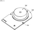
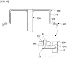
- FIG. 1 is a cross-sectional view illustrating a motor according to a first embodiment
- FIG. 2 is an exploded perspective view illustrating the motor illustrated in FIG. 1
- FIG. 3 is a view illustrating a yoke illustrated in FIG. 2 .
- the motor according to the first embodiment includes a shaft 100, a stator 200, a yoke 300, a first magnet 400, a second magnet 500, a circuit board 600, a base 700, a bearing housing 800, and bearings 900.
- the shaft 100 serves as an axis of rotation of the yoke 300.
- the shaft 100 does not rotate and is fixed to the base 700.
- a front end of the shaft 100 may be connected to a sensor device configured to obtain distance information.
- the stator 200 is disposed outside the shaft 100.
- the stator 200 includes a core 210.
- the core 210 includes a plurality of teeth. Coils are wound around the teeth.
- the stator 200 may include an insulator 220.
- the insulator 220 is coupled to the core 210.
- the yoke 300 is disposed outside the stator 200. In addition, the yoke 300 is coupled to the shaft 100. The shaft 100 is positioned at a center of the yoke 300. The shaft 100 is also rotated due to the rotation of the yoke 300.
- the first magnet 400 may be disposed in the yoke 300.
- the first magnet 400 is for driving the yoke 300.
- the yoke 300 is rotated due to an electromagnetic interaction between the first magnet 400 and the stator 200 around which coils are wound.
- the first magnet 400 may be one annual member.
- the first magnet 400 may be a plurality of divided magnets which are combined.
- the second magnet 500 may be disposed on a circumference of the yoke 300.
- the second magnet 500 is for detecting a position of the yoke 300 to achieve constant speed driving of the motor by detecting one rotation of the motor.
- the second magnet 500 may have an annular shape.
- the second magnet 500 may be formed with a plurality of divided magnets.
- the circuit board 600 is disposed under the stator 200.
- the circuit board 600 may include a first Hall sensor 610 and a second Hall sensor 620.
- the first Hall sensor 610 detects a magnetic flux of the first magnet 400.
- the second Hall sensor 620 detects a magnetic flux of the second magnet 500.
- the first Hall sensor 610 may be disposed under the first magnet 400.
- the second Hall sensor 620 may be disposed under the second magnet 500.
- a hole 630 through which the bearing housing 800 passes is disposed in the circuit board 600.
- the base 700 is disposed under the circuit board 600.
- the circuit board 600 may be disposed on an upper surface of the base 700.
- An adhesive film 710 for coupling the base 700 and the circuit board 600 may be positioned between the base 700 and the circuit board 600.
- a hole through which the bearing housing 800 passes is disposed in the base 700.
- the bearing housing 800 includes the bearings 900 therein.
- the bearings 900 rotatably support the shaft 100.
- the bearings 900 may be disposed in upper and lower portions of the bearing housing 800.
- the bearing housing 800 may include a first accommodation portion 810 and a second accommodation portion 820.
- the bearing 900 is disposed in the first accommodation portion 810.
- the bearing 900 is also disposed in the second accommodation portion 820.
- a partition wall 830 may be disposed between the first accommodation portion 810 and the second accommodation portion 820. The partition wall 830 protrudes in the bearing housing 800 to divide the first accommodation portion 810 from the second accommodation portion 820 and supports outer wheels of the bearings 900 in a shaft direction.
- the bearing housing 800 is fixed to the base 700, and the bearing housing 800 is coupled to a center of the core 210 of the stator 200.
- FIG. 4 is a side cross-sectional view illustrating the motor illustrated in FIG. 1 .
- the yoke 300 includes a body 310 having a cylindrical shape and a flange 320.
- An upper side of the body 310 has a shape closed by an upper surface thereof, and a lower side of the body 310 has an open shape.
- the flange 320 has a shape laterally extending from a lower end of the body 310.
- the shaft 100 is coupled to the upper surface of the body 310, and the shaft 100 and the yoke 300 rotate together.
- a hole 301 is disposed at a center of the upper surface of the body 310. An end portion of the shaft 100 may be press-inserted into and coupled to the hole 301.
- the magnet 400 is coupled to an inner circumferential surface of the body 310.
- the second magnet 500 is coupled to a lower surface of the flange 320.
- a thickness t1 of the body 310 may be equal to a thickness t2 of the flange 320.
- FIG. 5 is a view illustrating the circuit board including the first Hall sensor and the second Hall sensor
- FIG. 6 is a view illustrating a controller, the first Hall sensor, and the second Hall sensor.
- the first Hall sensor 610 is positioned under the first magnet 400.
- the first Hall sensor 610 may be disposed along a rotation orbit O1 of the first magnet 400 about a rotation center C of the yoke 300.
- Three first Hall sensors 610 may be disposed.
- Three first Hall sensors 610 generate three sensing signals.
- a controller 1000 of the motor determines a position of the yoke 300 on the basis of the sensing signals generated by the first Hall sensors 610. For example, in a case in which the first magnet 400 has eight poles and three first Hall sensors 610 are provided, an angular unit for measuring rotation is 15° based on one rotation (360°) of the yoke 300.
- a sensing signal S1 generated by the three first Hall sensors 610 has a pulse waveform in each rotation angle of 15°.
- the angular unit for measuring rotation is 15°, it is difficult to precisely measure whether a speed of the motor is constant. Accordingly, whether a speed of the motor is constant is more precisely determined using the second magnet 500 and the second Hall sensor 620.
- the second Hall sensor 620 is disposed under the second magnet 500.
- the second Hall sensor 620 may be disposed along a rotation orbit O2 of the second magnet 500 about a rotation center of the second magnet 500.
- the second Hall sensor 620 may be disposed outside the first Hall sensor 610 about the rotation center of the yoke 300 in a radial direction.
- the second Hall sensor 620 may be disposed in plurality. Since the second magnet 500 is provided as the plurality of divided magnets, the second Hall sensor 620 generates a sensing signal S2 having a pulse waveform with a period shorter than a period of a sensing signal generated by the first Hall sensor 610.
- the controller 1000 of the motor may detect whether a rotation speed of the motor is constant on the basis of the sensing signal generated by the second Hall sensor 620.
- an angular unit for measuring rotation is 2.5° based on one rotation (360°) of the yoke 300. Accordingly, since a sensing signal S2 generated by the two second Hall sensors 620 has a pulse waveform in each rotation angle of 2.5°, the number of rotations per minute of the motor may be checked more precisely.
- the yoke 300 includes the flange 320 having an annular shape.
- the flange 320 may include a first groove H1 and a second groove H2.
- the first groove H1 has an open portion in a direction opposite to an open portion of the second groove H1.
- the open portion of the first groove H1 faces the circuit board 600.
- the first groove H1 may be disposed outside the second groove H2.
- the second magnet 500 is disposed in the first groove H1.
- the second magnet 500 disposed in the first groove H1 faces the second Hall sensor 620.
- the first groove H1 may have an annular shape corresponding to the annular shape of the second magnet 500.
- the first groove H1 may be disposed along an outer circumferential surface of the body 310.
- a width W of the first groove H1 may be greater than the thickness t1 of the body 310. This is for effectively preventing mutual interference between a magnetic flux due to the first magnet 400 and a magnetic flux due to the second magnet 500.
- the flange 320 of the yoke 300 may include a first bent portion 321, a second bent portion 322, a third bent portion 323, and a fourth bent portion 324.
- the first bent portion 321 extends perpendicularly from the body 310.
- the second bent portion 322 extends from the first bent portion 321 in a direction away from the circuit board 600.
- the third bent portion 323 extends perpendicularly from the second bent portion 322.
- the fourth bent portion 324 extends from the third bent portion 323 in a direction close to the circuit board 600.
- the second bent portion 322, the third bent portion 323, and the fourth bent portion 324 form the first groove H1.
- the first bent portion 321, the second bent portion 322, and the third bent portion 323 form the second groove H2.
- a separation space S is formed between the body 310 and the second bent portion 322.
- the separation space S prevents mutual interference between the magnetic flux due to the first magnet 400 and the magnetic flux due to the second magnet 500 to reduce influence of the first magnet 400 on a sensing signal of the second Hall sensor 620 so that there is an advantage of precisely detecting whether a speed of the motor is constant.
- FIG. 7 is a view illustrating an outer diameter of the yoke and a first angle of the second magnet.
- the second magnet 500 may include a plurality of divided magnets divided at a first angle ⁇ about a center of the shaft.
- the first angle ⁇ may be 2.5° or less.
- a width L between an outer diameter R1 and an inner diameter R2 of the second magnet 500 may be less than 7 mm.
- a second magnet 500 may be directly insertion-injected into and disposed in a flange 320.
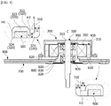
- FIG. 8 is a cross-sectional view illustrating the motor according to the second embodiment
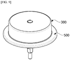
- FIG. 9 is a perspective view illustrating a yoke and the second magnet illustrated in FIG. 8
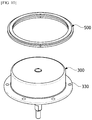
- FIG. 10 is an exploded view illustrating the yoke and the second magnet illustrated in FIG. 9
- FIG. 11 is a side cross-sectional view illustrating the yoke and the second magnet illustrated in FIG. 8 .
- the flange 320 may include holes 330, and the second magnet 500 may include an upper portion 510, a lower portion 520, and a connection portion 530.
- the plurality of holes 330 are provided.
- the holes 330 may be disposed to be rotationally symmetrical about a rotation center of a yoke 300. This is to maintain rotation balance of the yoke 300.
- the upper portion 510 of the second magnet 500 is disposed on an upper surface of the flange 320.
- the lower portion 520 of the second magnet 500 is disposed on a lower surface of the flange 320.
- the connection portion 530 is disposed in the hole 330 and connects the upper portion 510 and the lower portion 520.
- the lower portion 520 of the second magnet 500 is disposed to face a second Hall sensor 620.
- an outer diameter D1 of the upper portion 510 may be smaller than an outer diameter D2 of the lower portion 520.
- a structure in which the flange 320 is disposed between the upper portion 510 and the lower portion 520 prevents the second magnet 500 from being separated from the yoke 300 in a shaft direction.
- the connection portion 530 disposed in the hole 330 of the flange 320 prevents the second magnet 500 from being separated from the yoke 300 in a rotation direction of the yoke 300.
- FIG. 12 is a cross-sectional view illustrating a motor according to a third embodiment
- FIG. 13 is a perspective view illustrating a yoke and a second magnet illustrated in FIG. 12
- FIG. 14 is an exploded view illustrating the yoke and the second magnet illustrated in FIG. 12
- FIG. 15 is a side cross-sectional view illustrating the yoke and the second magnet illustrated in FIG. 12 .
- a flange 320 and a second magnet 500 may be coupled using connection members 10 which are insertion-injected into the flange 320 and the second magnet 500.
- the flange 320 may include a plurality of holes 340.
- the holes 340 may be disposed to be rotationally symmetrical about a rotation center of a yoke 300.
- the second magnet 500 has an annular shape, and third grooves 540 are disposed in an inner circumferential surface thereof.
- the connection member 10 may have an annular shape.
- the connection member 10 may include a first protrusion 11 and a second protrusion 12. The first protrusion 11 protrudes upward from an upper surface of the connection member 10.
- the first protrusion 11 is disposed in the hole 340.
- the first protrusion 11 has a cylindrical shape.
- the first protrusion 11 is provided as a plurality of first protrusions to be disposed in each of the holes 340.
- the first protrusion 11 passes through the hole 340 and protrudes upward from an upper surface of the flange 320.
- the second protrusion 12 protrudes outward from an outer circumferential surface of the connection member 10.
- the second protrusion 12 is disposed in the third groove 540 of the second magnet 500.
- the second protrusion 12 is provided as a plurality of second protrusions, and the number of the second protrusions 12 may correspond to the number of the third grooves 540 of the second magnet 500.
- the second magnet 500 may be disposed outside the connection member 10. An inner diameter of the second magnet 500 may be greater than an outer diameter of the flange 320.
Landscapes
- Engineering & Computer Science (AREA)
- Power Engineering (AREA)
- Microelectronics & Electronic Packaging (AREA)
- Brushless Motors (AREA)
Applications Claiming Priority (2)
| Application Number | Priority Date | Filing Date | Title |
|---|---|---|---|
| KR1020180041653A KR102583066B1 (ko) | 2018-04-10 | 2018-04-10 | 모터 |
| PCT/KR2019/004285 WO2019199056A1 (ko) | 2018-04-10 | 2019-04-10 | 모터 |
Publications (3)
| Publication Number | Publication Date |
|---|---|
| EP3780352A1 true EP3780352A1 (de) | 2021-02-17 |
| EP3780352A4 EP3780352A4 (de) | 2021-08-18 |
| EP3780352B1 EP3780352B1 (de) | 2023-10-18 |
Family
ID=68163662
Family Applications (1)
| Application Number | Title | Priority Date | Filing Date |
|---|---|---|---|
| EP19785912.7A Active EP3780352B1 (de) | 2018-04-10 | 2019-04-10 | Motor |
Country Status (5)
| Country | Link |
|---|---|
| US (1) | US11411471B2 (de) |
| EP (1) | EP3780352B1 (de) |
| KR (1) | KR102583066B1 (de) |
| CN (1) | CN111971875B (de) |
| WO (1) | WO2019199056A1 (de) |
Cited By (1)
| Publication number | Priority date | Publication date | Assignee | Title |
|---|---|---|---|---|
| US11876479B2 (en) | 2020-01-29 | 2024-01-16 | Cepheid | Motor having integrated actuator with absolute encoder and methods of use |
Families Citing this family (9)
| Publication number | Priority date | Publication date | Assignee | Title |
|---|---|---|---|---|
| KR102897210B1 (ko) * | 2019-10-31 | 2025-12-10 | 엘지이노텍 주식회사 | 모터 |
| KR102896996B1 (ko) * | 2019-12-18 | 2025-12-08 | 엘지이노텍 주식회사 | 모터 |
| US11437900B2 (en) | 2019-12-19 | 2022-09-06 | Black & Decker Inc. | Modular outer-rotor brushless motor for a power tool |
| US11757330B2 (en) | 2019-12-19 | 2023-09-12 | Black & Decker, Inc. | Canned outer-rotor brushless motor for a power tool |
| EP4096072A4 (de) * | 2020-01-20 | 2024-05-15 | LG Innotek Co., Ltd. | Motor |
| KR102897214B1 (ko) * | 2020-02-07 | 2025-12-10 | 엘지이노텍 주식회사 | 모터 |
| KR102865159B1 (ko) * | 2020-02-05 | 2025-09-29 | 엘지이노텍 주식회사 | 모터 |
| JP7400596B2 (ja) * | 2020-03-31 | 2023-12-19 | 株式会社富士通ゼネラル | 永久磁石電動機 |
| US12176794B2 (en) | 2021-11-19 | 2024-12-24 | Black & Decker Inc. | Outer-rotor brushless motor for a power tool |
Family Cites Families (22)
| Publication number | Priority date | Publication date | Assignee | Title |
|---|---|---|---|---|
| JPH0528594Y2 (de) * | 1986-12-03 | 1993-07-22 | ||
| US5254895A (en) * | 1990-08-06 | 1993-10-19 | Canon Denshi Kabushiki Kaisha | Motor for disc drive |
| US5245234A (en) * | 1990-12-28 | 1993-09-14 | Nippon Densan Corporation | Motor |
| US5408153A (en) * | 1991-07-05 | 1995-04-18 | Canon Denshi Kabushiki Kaisha | Index position detecting apparatus for an electromagnetic rotary machine |
| JPH0526611A (ja) * | 1991-07-25 | 1993-02-02 | Matsushita Electric Ind Co Ltd | パルス発生装置 |
| US5825586A (en) * | 1992-05-08 | 1998-10-20 | Matsushita Electric Industrial Co., Ltd. | Disk drive motor having a drive pin assembly which facilitates stabilized chucking of a disk |
| JP2854519B2 (ja) * | 1994-02-07 | 1999-02-03 | 株式会社三協精機製作所 | ブラシレスモータ |
| JP2002354768A (ja) * | 2001-05-24 | 2002-12-06 | Sankyo Seiki Mfg Co Ltd | モータ |
| EP1516418B1 (de) * | 2002-06-26 | 2011-03-23 | Amotech Co., Ltd. | Bürstenloser Gleichstrommotor mit einem radialen Kern und einer Struktur mit einem Doppelrotor |
| KR100564442B1 (ko) | 2003-12-10 | 2006-03-29 | 엘지전자 주식회사 | 탑로딩방식 드럼 세탁기 |
| JP4842893B2 (ja) | 2007-03-07 | 2011-12-21 | アスモ株式会社 | 歯車機構及び減速機付モータ |
| US8283915B2 (en) | 2007-03-07 | 2012-10-09 | Asmo Co., Ltd. | Sensor magnet device, gear mechanism and speed reducing electric motor |
| JP5501572B2 (ja) * | 2008-04-25 | 2014-05-21 | 株式会社ジェイテクト | モーターのローター及び電動パワーステアリング装置 |
| KR101088704B1 (ko) * | 2010-01-04 | 2011-12-01 | 삼성전기주식회사 | 베어링 홀더 및 이를 구비한 모터 |
| KR101787755B1 (ko) | 2011-04-15 | 2017-10-18 | 엘지이노텍 주식회사 | Eps모터의 센싱 마그네트 결합구조 |
| KR20130073385A (ko) * | 2011-12-23 | 2013-07-03 | 엘지이노텍 주식회사 | 스핀들 모터 |
| TWI567295B (zh) * | 2013-02-26 | 2017-01-21 | 山葉發動機股份有限公司 | 旋轉電機、引擎及車輛 |
| JP2015037366A (ja) | 2013-08-14 | 2015-02-23 | ヤマハ発動機株式会社 | 回転電機、エンジン及び車両 |
| JP5761254B2 (ja) * | 2013-05-27 | 2015-08-12 | 株式会社デンソー | 回転電機 |
| CN203596711U (zh) * | 2013-11-20 | 2014-05-14 | 日本电产株式会社 | 外转子型马达 |
| JP2015114209A (ja) * | 2013-12-12 | 2015-06-22 | セイコーエプソン株式会社 | エンコーダー及び電気機械装置 |
| JP6017526B2 (ja) * | 2014-12-17 | 2016-11-02 | シナノケンシ株式会社 | 回転体駆動装置 |
-
2018
- 2018-04-10 KR KR1020180041653A patent/KR102583066B1/ko active Active
-
2019
- 2019-04-10 US US17/046,480 patent/US11411471B2/en active Active
- 2019-04-10 CN CN201980025260.5A patent/CN111971875B/zh active Active
- 2019-04-10 EP EP19785912.7A patent/EP3780352B1/de active Active
- 2019-04-10 WO PCT/KR2019/004285 patent/WO2019199056A1/ko not_active Ceased
Cited By (1)
| Publication number | Priority date | Publication date | Assignee | Title |
|---|---|---|---|---|
| US11876479B2 (en) | 2020-01-29 | 2024-01-16 | Cepheid | Motor having integrated actuator with absolute encoder and methods of use |
Also Published As
| Publication number | Publication date |
|---|---|
| US11411471B2 (en) | 2022-08-09 |
| CN111971875A (zh) | 2020-11-20 |
| WO2019199056A1 (ko) | 2019-10-17 |
| KR20190118395A (ko) | 2019-10-18 |
| KR102583066B1 (ko) | 2023-09-27 |
| EP3780352A4 (de) | 2021-08-18 |
| EP3780352B1 (de) | 2023-10-18 |
| CN111971875B (zh) | 2024-03-05 |
| US20210159765A1 (en) | 2021-05-27 |
Similar Documents
| Publication | Publication Date | Title |
|---|---|---|
| US11411471B2 (en) | Motor | |
| US9843241B2 (en) | Motor, motor system, and motor encoder | |
| US9391488B1 (en) | Rotary body driving apparatus | |
| JP2019533168A (ja) | トルクインデックスセンサおよびこれを含む操向装置 | |
| JP2012085445A (ja) | モータ | |
| KR102158101B1 (ko) | 센서 모듈, 및 이를 포함하는 모터 | |
| KR101775165B1 (ko) | 트랙션 모터 | |
| US11973456B2 (en) | Motor | |
| JP2014121254A (ja) | センシングモジュールおよびそれを含むモータ | |
| US11962201B2 (en) | Motor | |
| KR102897214B1 (ko) | 모터 | |
| EP3402056A1 (de) | Vorrichtung zur erfassung der position eines rotors und motor damit | |
| US11456636B2 (en) | Motor | |
| JPH0736469Y2 (ja) | ブラシレスモータ | |
| KR102897210B1 (ko) | 모터 | |
| KR102896996B1 (ko) | 모터 | |
| KR20190129479A (ko) | 모터 | |
| KR102606985B1 (ko) | 토크 인덱스 센서 및 이를 포함하는 조향 장치 | |
| JP2001264346A (ja) | 回転体の回転数若しくは位置検出装置とリラクタンスモータ | |
| JP2007043814A (ja) | 回転センサ内蔵モータ | |
| JPH04114770U (ja) | ブラシレスモータ | |
| JPH0736588U (ja) | ブラシレスモータ | |
| JP2018057235A (ja) | 回転センサ付き回転機 | |
| JP2017208879A (ja) | ブラシレスモータ | |
| JPH04124867U (ja) | 速度検出器付きモーター |
Legal Events
| Date | Code | Title | Description |
|---|---|---|---|
| STAA | Information on the status of an ep patent application or granted ep patent |
Free format text: STATUS: THE INTERNATIONAL PUBLICATION HAS BEEN MADE |
|
| PUAI | Public reference made under article 153(3) epc to a published international application that has entered the european phase |
Free format text: ORIGINAL CODE: 0009012 |
|
| STAA | Information on the status of an ep patent application or granted ep patent |
Free format text: STATUS: REQUEST FOR EXAMINATION WAS MADE |
|
| 17P | Request for examination filed |
Effective date: 20201106 |
|
| AK | Designated contracting states |
Kind code of ref document: A1 Designated state(s): AL AT BE BG CH CY CZ DE DK EE ES FI FR GB GR HR HU IE IS IT LI LT LU LV MC MK MT NL NO PL PT RO RS SE SI SK SM TR |
|
| AX | Request for extension of the european patent |
Extension state: BA ME |
|
| RIC1 | Information provided on ipc code assigned before grant |
Ipc: H02K 11/215 20160101AFI20210414BHEP Ipc: H02K 1/27 20060101ALN20210414BHEP Ipc: H02K 5/167 20060101ALN20210414BHEP |
|
| DAV | Request for validation of the european patent (deleted) | ||
| DAX | Request for extension of the european patent (deleted) | ||
| A4 | Supplementary search report drawn up and despatched |
Effective date: 20210721 |
|
| RIC1 | Information provided on ipc code assigned before grant |
Ipc: H02K 11/215 20160101AFI20210715BHEP Ipc: H02K 1/27 20060101ALN20210715BHEP Ipc: H02K 5/167 20060101ALN20210715BHEP |
|
| REG | Reference to a national code |
Ref country code: DE Ref legal event code: R079 Free format text: PREVIOUS MAIN CLASS: H02K0001270000 Ipc: H02K0011215000 Ref document number: 602019039680 Country of ref document: DE |
|
| GRAP | Despatch of communication of intention to grant a patent |
Free format text: ORIGINAL CODE: EPIDOSNIGR1 |
|
| STAA | Information on the status of an ep patent application or granted ep patent |
Free format text: STATUS: GRANT OF PATENT IS INTENDED |
|
| RIC1 | Information provided on ipc code assigned before grant |
Ipc: H02K 5/167 20060101ALN20230504BHEP Ipc: H02K 1/2791 20220101ALI20230504BHEP Ipc: H02K 11/215 20160101AFI20230504BHEP |
|
| INTG | Intention to grant announced |
Effective date: 20230523 |
|
| GRAS | Grant fee paid |
Free format text: ORIGINAL CODE: EPIDOSNIGR3 |
|
| GRAA | (expected) grant |
Free format text: ORIGINAL CODE: 0009210 |
|
| STAA | Information on the status of an ep patent application or granted ep patent |
Free format text: STATUS: THE PATENT HAS BEEN GRANTED |
|
| AK | Designated contracting states |
Kind code of ref document: B1 Designated state(s): AL AT BE BG CH CY CZ DE DK EE ES FI FR GB GR HR HU IE IS IT LI LT LU LV MC MK MT NL NO PL PT RO RS SE SI SK SM TR |
|
| REG | Reference to a national code |
Ref country code: GB Ref legal event code: FG4D |
|
| REG | Reference to a national code |
Ref country code: CH Ref legal event code: EP |
|
| REG | Reference to a national code |
Ref country code: IE Ref legal event code: FG4D |
|
| REG | Reference to a national code |
Ref country code: DE Ref legal event code: R096 Ref document number: 602019039680 Country of ref document: DE |
|
| REG | Reference to a national code |
Ref country code: LT Ref legal event code: MG9D |
|
| REG | Reference to a national code |
Ref country code: NL Ref legal event code: MP Effective date: 20231018 |
|
| REG | Reference to a national code |
Ref country code: AT Ref legal event code: MK05 Ref document number: 1623347 Country of ref document: AT Kind code of ref document: T Effective date: 20231018 |
|
| PG25 | Lapsed in a contracting state [announced via postgrant information from national office to epo] |
Ref country code: NL Free format text: LAPSE BECAUSE OF FAILURE TO SUBMIT A TRANSLATION OF THE DESCRIPTION OR TO PAY THE FEE WITHIN THE PRESCRIBED TIME-LIMIT Effective date: 20231018 |
|
| PG25 | Lapsed in a contracting state [announced via postgrant information from national office to epo] |
Ref country code: GR Free format text: LAPSE BECAUSE OF FAILURE TO SUBMIT A TRANSLATION OF THE DESCRIPTION OR TO PAY THE FEE WITHIN THE PRESCRIBED TIME-LIMIT Effective date: 20240119 |
|
| PG25 | Lapsed in a contracting state [announced via postgrant information from national office to epo] |
Ref country code: IS Free format text: LAPSE BECAUSE OF FAILURE TO SUBMIT A TRANSLATION OF THE DESCRIPTION OR TO PAY THE FEE WITHIN THE PRESCRIBED TIME-LIMIT Effective date: 20240218 |
|
| PG25 | Lapsed in a contracting state [announced via postgrant information from national office to epo] |
Ref country code: LT Free format text: LAPSE BECAUSE OF FAILURE TO SUBMIT A TRANSLATION OF THE DESCRIPTION OR TO PAY THE FEE WITHIN THE PRESCRIBED TIME-LIMIT Effective date: 20231018 |
|
| PG25 | Lapsed in a contracting state [announced via postgrant information from national office to epo] |
Ref country code: AT Free format text: LAPSE BECAUSE OF FAILURE TO SUBMIT A TRANSLATION OF THE DESCRIPTION OR TO PAY THE FEE WITHIN THE PRESCRIBED TIME-LIMIT Effective date: 20231018 |
|
| PG25 | Lapsed in a contracting state [announced via postgrant information from national office to epo] |
Ref country code: ES Free format text: LAPSE BECAUSE OF FAILURE TO SUBMIT A TRANSLATION OF THE DESCRIPTION OR TO PAY THE FEE WITHIN THE PRESCRIBED TIME-LIMIT Effective date: 20231018 |
|
| PG25 | Lapsed in a contracting state [announced via postgrant information from national office to epo] |
Ref country code: LT Free format text: LAPSE BECAUSE OF FAILURE TO SUBMIT A TRANSLATION OF THE DESCRIPTION OR TO PAY THE FEE WITHIN THE PRESCRIBED TIME-LIMIT Effective date: 20231018 Ref country code: IS Free format text: LAPSE BECAUSE OF FAILURE TO SUBMIT A TRANSLATION OF THE DESCRIPTION OR TO PAY THE FEE WITHIN THE PRESCRIBED TIME-LIMIT Effective date: 20240218 Ref country code: GR Free format text: LAPSE BECAUSE OF FAILURE TO SUBMIT A TRANSLATION OF THE DESCRIPTION OR TO PAY THE FEE WITHIN THE PRESCRIBED TIME-LIMIT Effective date: 20240119 Ref country code: ES Free format text: LAPSE BECAUSE OF FAILURE TO SUBMIT A TRANSLATION OF THE DESCRIPTION OR TO PAY THE FEE WITHIN THE PRESCRIBED TIME-LIMIT Effective date: 20231018 Ref country code: BG Free format text: LAPSE BECAUSE OF FAILURE TO SUBMIT A TRANSLATION OF THE DESCRIPTION OR TO PAY THE FEE WITHIN THE PRESCRIBED TIME-LIMIT Effective date: 20240118 Ref country code: AT Free format text: LAPSE BECAUSE OF FAILURE TO SUBMIT A TRANSLATION OF THE DESCRIPTION OR TO PAY THE FEE WITHIN THE PRESCRIBED TIME-LIMIT Effective date: 20231018 Ref country code: PT Free format text: LAPSE BECAUSE OF FAILURE TO SUBMIT A TRANSLATION OF THE DESCRIPTION OR TO PAY THE FEE WITHIN THE PRESCRIBED TIME-LIMIT Effective date: 20240219 |
|
| PG25 | Lapsed in a contracting state [announced via postgrant information from national office to epo] |
Ref country code: SE Free format text: LAPSE BECAUSE OF FAILURE TO SUBMIT A TRANSLATION OF THE DESCRIPTION OR TO PAY THE FEE WITHIN THE PRESCRIBED TIME-LIMIT Effective date: 20231018 Ref country code: RS Free format text: LAPSE BECAUSE OF FAILURE TO SUBMIT A TRANSLATION OF THE DESCRIPTION OR TO PAY THE FEE WITHIN THE PRESCRIBED TIME-LIMIT Effective date: 20231018 Ref country code: PL Free format text: LAPSE BECAUSE OF FAILURE TO SUBMIT A TRANSLATION OF THE DESCRIPTION OR TO PAY THE FEE WITHIN THE PRESCRIBED TIME-LIMIT Effective date: 20231018 Ref country code: NO Free format text: LAPSE BECAUSE OF FAILURE TO SUBMIT A TRANSLATION OF THE DESCRIPTION OR TO PAY THE FEE WITHIN THE PRESCRIBED TIME-LIMIT Effective date: 20240118 Ref country code: LV Free format text: LAPSE BECAUSE OF FAILURE TO SUBMIT A TRANSLATION OF THE DESCRIPTION OR TO PAY THE FEE WITHIN THE PRESCRIBED TIME-LIMIT Effective date: 20231018 Ref country code: HR Free format text: LAPSE BECAUSE OF FAILURE TO SUBMIT A TRANSLATION OF THE DESCRIPTION OR TO PAY THE FEE WITHIN THE PRESCRIBED TIME-LIMIT Effective date: 20231018 |
|
| PG25 | Lapsed in a contracting state [announced via postgrant information from national office to epo] |
Ref country code: DK Free format text: LAPSE BECAUSE OF FAILURE TO SUBMIT A TRANSLATION OF THE DESCRIPTION OR TO PAY THE FEE WITHIN THE PRESCRIBED TIME-LIMIT Effective date: 20231018 |
|
| REG | Reference to a national code |
Ref country code: DE Ref legal event code: R097 Ref document number: 602019039680 Country of ref document: DE |
|
| PG25 | Lapsed in a contracting state [announced via postgrant information from national office to epo] |
Ref country code: CZ Free format text: LAPSE BECAUSE OF FAILURE TO SUBMIT A TRANSLATION OF THE DESCRIPTION OR TO PAY THE FEE WITHIN THE PRESCRIBED TIME-LIMIT Effective date: 20231018 |
|
| PG25 | Lapsed in a contracting state [announced via postgrant information from national office to epo] |
Ref country code: SK Free format text: LAPSE BECAUSE OF FAILURE TO SUBMIT A TRANSLATION OF THE DESCRIPTION OR TO PAY THE FEE WITHIN THE PRESCRIBED TIME-LIMIT Effective date: 20231018 |
|
| PG25 | Lapsed in a contracting state [announced via postgrant information from national office to epo] |
Ref country code: SM Free format text: LAPSE BECAUSE OF FAILURE TO SUBMIT A TRANSLATION OF THE DESCRIPTION OR TO PAY THE FEE WITHIN THE PRESCRIBED TIME-LIMIT Effective date: 20231018 Ref country code: SK Free format text: LAPSE BECAUSE OF FAILURE TO SUBMIT A TRANSLATION OF THE DESCRIPTION OR TO PAY THE FEE WITHIN THE PRESCRIBED TIME-LIMIT Effective date: 20231018 Ref country code: RO Free format text: LAPSE BECAUSE OF FAILURE TO SUBMIT A TRANSLATION OF THE DESCRIPTION OR TO PAY THE FEE WITHIN THE PRESCRIBED TIME-LIMIT Effective date: 20231018 Ref country code: IT Free format text: LAPSE BECAUSE OF FAILURE TO SUBMIT A TRANSLATION OF THE DESCRIPTION OR TO PAY THE FEE WITHIN THE PRESCRIBED TIME-LIMIT Effective date: 20231018 Ref country code: EE Free format text: LAPSE BECAUSE OF FAILURE TO SUBMIT A TRANSLATION OF THE DESCRIPTION OR TO PAY THE FEE WITHIN THE PRESCRIBED TIME-LIMIT Effective date: 20231018 Ref country code: DK Free format text: LAPSE BECAUSE OF FAILURE TO SUBMIT A TRANSLATION OF THE DESCRIPTION OR TO PAY THE FEE WITHIN THE PRESCRIBED TIME-LIMIT Effective date: 20231018 Ref country code: CZ Free format text: LAPSE BECAUSE OF FAILURE TO SUBMIT A TRANSLATION OF THE DESCRIPTION OR TO PAY THE FEE WITHIN THE PRESCRIBED TIME-LIMIT Effective date: 20231018 |
|
| PLBE | No opposition filed within time limit |
Free format text: ORIGINAL CODE: 0009261 |
|
| STAA | Information on the status of an ep patent application or granted ep patent |
Free format text: STATUS: NO OPPOSITION FILED WITHIN TIME LIMIT |
|
| 26N | No opposition filed |
Effective date: 20240719 |
|
| PG25 | Lapsed in a contracting state [announced via postgrant information from national office to epo] |
Ref country code: SI Free format text: LAPSE BECAUSE OF FAILURE TO SUBMIT A TRANSLATION OF THE DESCRIPTION OR TO PAY THE FEE WITHIN THE PRESCRIBED TIME-LIMIT Effective date: 20231018 |
|
| PG25 | Lapsed in a contracting state [announced via postgrant information from national office to epo] |
Ref country code: SI Free format text: LAPSE BECAUSE OF FAILURE TO SUBMIT A TRANSLATION OF THE DESCRIPTION OR TO PAY THE FEE WITHIN THE PRESCRIBED TIME-LIMIT Effective date: 20231018 |
|
| PG25 | Lapsed in a contracting state [announced via postgrant information from national office to epo] |
Ref country code: MC Free format text: LAPSE BECAUSE OF FAILURE TO SUBMIT A TRANSLATION OF THE DESCRIPTION OR TO PAY THE FEE WITHIN THE PRESCRIBED TIME-LIMIT Effective date: 20231018 |
|
| PG25 | Lapsed in a contracting state [announced via postgrant information from national office to epo] |
Ref country code: MC Free format text: LAPSE BECAUSE OF FAILURE TO SUBMIT A TRANSLATION OF THE DESCRIPTION OR TO PAY THE FEE WITHIN THE PRESCRIBED TIME-LIMIT Effective date: 20231018 |
|
| REG | Reference to a national code |
Ref country code: CH Ref legal event code: PL |
|
| PG25 | Lapsed in a contracting state [announced via postgrant information from national office to epo] |
Ref country code: LU Free format text: LAPSE BECAUSE OF NON-PAYMENT OF DUE FEES Effective date: 20240410 |
|
| GBPC | Gb: european patent ceased through non-payment of renewal fee |
Effective date: 20240410 |
|
| REG | Reference to a national code |
Ref country code: BE Ref legal event code: MM Effective date: 20240430 |
|
| PG25 | Lapsed in a contracting state [announced via postgrant information from national office to epo] |
Ref country code: LU Free format text: LAPSE BECAUSE OF NON-PAYMENT OF DUE FEES Effective date: 20240410 |
|
| PG25 | Lapsed in a contracting state [announced via postgrant information from national office to epo] |
Ref country code: BE Free format text: LAPSE BECAUSE OF NON-PAYMENT OF DUE FEES Effective date: 20240430 |
|
| PG25 | Lapsed in a contracting state [announced via postgrant information from national office to epo] |
Ref country code: GB Free format text: LAPSE BECAUSE OF NON-PAYMENT OF DUE FEES Effective date: 20240410 |
|
| PG25 | Lapsed in a contracting state [announced via postgrant information from national office to epo] |
Ref country code: GB Free format text: LAPSE BECAUSE OF NON-PAYMENT OF DUE FEES Effective date: 20240410 Ref country code: BE Free format text: LAPSE BECAUSE OF NON-PAYMENT OF DUE FEES Effective date: 20240430 Ref country code: CH Free format text: LAPSE BECAUSE OF NON-PAYMENT OF DUE FEES Effective date: 20240430 |
|
| PG25 | Lapsed in a contracting state [announced via postgrant information from national office to epo] |
Ref country code: IE Free format text: LAPSE BECAUSE OF NON-PAYMENT OF DUE FEES Effective date: 20240410 |
|
| PGFP | Annual fee paid to national office [announced via postgrant information from national office to epo] |
Ref country code: FR Payment date: 20250321 Year of fee payment: 7 |
|
| PGFP | Annual fee paid to national office [announced via postgrant information from national office to epo] |
Ref country code: DE Payment date: 20250320 Year of fee payment: 7 |
|
| PG25 | Lapsed in a contracting state [announced via postgrant information from national office to epo] |
Ref country code: CY Free format text: LAPSE BECAUSE OF FAILURE TO SUBMIT A TRANSLATION OF THE DESCRIPTION OR TO PAY THE FEE WITHIN THE PRESCRIBED TIME-LIMIT; INVALID AB INITIO Effective date: 20190410 |
|
| PG25 | Lapsed in a contracting state [announced via postgrant information from national office to epo] |
Ref country code: HU Free format text: LAPSE BECAUSE OF FAILURE TO SUBMIT A TRANSLATION OF THE DESCRIPTION OR TO PAY THE FEE WITHIN THE PRESCRIBED TIME-LIMIT; INVALID AB INITIO Effective date: 20190410 |
|
| PG25 | Lapsed in a contracting state [announced via postgrant information from national office to epo] |
Ref country code: FI Free format text: LAPSE BECAUSE OF FAILURE TO SUBMIT A TRANSLATION OF THE DESCRIPTION OR TO PAY THE FEE WITHIN THE PRESCRIBED TIME-LIMIT Effective date: 20231019 |