EP3779401B1 - Messvorrichtung - Google Patents
Messvorrichtung Download PDFInfo
- Publication number
- EP3779401B1 EP3779401B1 EP19777411.0A EP19777411A EP3779401B1 EP 3779401 B1 EP3779401 B1 EP 3779401B1 EP 19777411 A EP19777411 A EP 19777411A EP 3779401 B1 EP3779401 B1 EP 3779401B1
- Authority
- EP
- European Patent Office
- Prior art keywords
- heat regulation
- voltage
- temperature
- regulation mechanism
- sensor
- Prior art date
- Legal status (The legal status is an assumption and is not a legal conclusion. Google has not performed a legal analysis and makes no representation as to the accuracy of the status listed.)
- Active
Links
Images



Classifications
-
- G—PHYSICS
- G01—MEASURING; TESTING
- G01N—INVESTIGATING OR ANALYSING MATERIALS BY DETERMINING THEIR CHEMICAL OR PHYSICAL PROPERTIES
- G01N15/00—Investigating characteristics of particles; Investigating permeability, pore-volume or surface-area of porous materials
- G01N15/06—Investigating concentration of particle suspensions
- G01N15/0606—Investigating concentration of particle suspensions by collecting particles on a support
- G01N15/0637—Moving support
-
- H—ELECTRICITY
- H10—SEMICONDUCTOR DEVICES; ELECTRIC SOLID-STATE DEVICES NOT OTHERWISE PROVIDED FOR
- H10N—ELECTRIC SOLID-STATE DEVICES NOT OTHERWISE PROVIDED FOR
- H10N10/00—Thermoelectric devices comprising a junction of dissimilar materials, i.e. devices exhibiting Seebeck or Peltier effects
- H10N10/10—Thermoelectric devices comprising a junction of dissimilar materials, i.e. devices exhibiting Seebeck or Peltier effects operating with only the Peltier or Seebeck effects
- H10N10/17—Thermoelectric devices comprising a junction of dissimilar materials, i.e. devices exhibiting Seebeck or Peltier effects operating with only the Peltier or Seebeck effects characterised by the structure or configuration of the cell or thermocouple forming the device
-
- G—PHYSICS
- G01—MEASURING; TESTING
- G01N—INVESTIGATING OR ANALYSING MATERIALS BY DETERMINING THEIR CHEMICAL OR PHYSICAL PROPERTIES
- G01N29/00—Investigating or analysing materials by the use of ultrasonic, sonic or infrasonic waves; Visualisation of the interior of objects by transmitting ultrasonic or sonic waves through the object
- G01N29/02—Analysing fluids
- G01N29/036—Analysing fluids by measuring frequency or resonance of acoustic waves
-
- G—PHYSICS
- G01—MEASURING; TESTING
- G01N—INVESTIGATING OR ANALYSING MATERIALS BY DETERMINING THEIR CHEMICAL OR PHYSICAL PROPERTIES
- G01N29/00—Investigating or analysing materials by the use of ultrasonic, sonic or infrasonic waves; Visualisation of the interior of objects by transmitting ultrasonic or sonic waves through the object
- G01N29/22—Details, e.g. general constructional or apparatus details
- G01N29/32—Arrangements for suppressing undesired influences, e.g. temperature or pressure variations, compensating for signal noise
- G01N29/326—Arrangements for suppressing undesired influences, e.g. temperature or pressure variations, compensating for signal noise compensating for temperature variations
-
- H—ELECTRICITY
- H02—GENERATION; CONVERSION OR DISTRIBUTION OF ELECTRIC POWER
- H02N—ELECTRIC MACHINES NOT OTHERWISE PROVIDED FOR
- H02N2/00—Electric machines in general using piezoelectric effect, electrostriction or magnetostriction
- H02N2/18—Electric machines in general using piezoelectric effect, electrostriction or magnetostriction producing electrical output from mechanical input, e.g. generators
- H02N2/186—Vibration harvesters
- H02N2/188—Vibration harvesters adapted for resonant operation
-
- H—ELECTRICITY
- H03—ELECTRONIC CIRCUITRY
- H03B—GENERATION OF OSCILLATIONS, DIRECTLY OR BY FREQUENCY-CHANGING, BY CIRCUITS EMPLOYING ACTIVE ELEMENTS WHICH OPERATE IN A NON-SWITCHING MANNER; GENERATION OF NOISE BY SUCH CIRCUITS
- H03B5/00—Generation of oscillations using amplifier with regenerative feedback from output to input
- H03B5/30—Generation of oscillations using amplifier with regenerative feedback from output to input with frequency-determining element being electromechanical resonator
- H03B5/32—Generation of oscillations using amplifier with regenerative feedback from output to input with frequency-determining element being electromechanical resonator being a piezoelectric resonator
-
- G—PHYSICS
- G01—MEASURING; TESTING
- G01N—INVESTIGATING OR ANALYSING MATERIALS BY DETERMINING THEIR CHEMICAL OR PHYSICAL PROPERTIES
- G01N2291/00—Indexing codes associated with group G01N29/00
- G01N2291/02—Indexing codes associated with the analysed material
- G01N2291/025—Change of phase or condition
- G01N2291/0255—(Bio)chemical reactions, e.g. on biosensors
-
- G—PHYSICS
- G01—MEASURING; TESTING
- G01N—INVESTIGATING OR ANALYSING MATERIALS BY DETERMINING THEIR CHEMICAL OR PHYSICAL PROPERTIES
- G01N2291/00—Indexing codes associated with group G01N29/00
- G01N2291/02—Indexing codes associated with the analysed material
- G01N2291/025—Change of phase or condition
- G01N2291/0256—Adsorption, desorption, surface mass change, e.g. on biosensors
-
- G—PHYSICS
- G01—MEASURING; TESTING
- G01N—INVESTIGATING OR ANALYSING MATERIALS BY DETERMINING THEIR CHEMICAL OR PHYSICAL PROPERTIES
- G01N2291/00—Indexing codes associated with group G01N29/00
- G01N2291/04—Wave modes and trajectories
- G01N2291/042—Wave modes
- G01N2291/0422—Shear waves, transverse waves, horizontally polarised waves
-
- G—PHYSICS
- G01—MEASURING; TESTING
- G01N—INVESTIGATING OR ANALYSING MATERIALS BY DETERMINING THEIR CHEMICAL OR PHYSICAL PROPERTIES
- G01N2291/00—Indexing codes associated with group G01N29/00
- G01N2291/04—Wave modes and trajectories
- G01N2291/042—Wave modes
- G01N2291/0426—Bulk waves, e.g. quartz crystal microbalance, torsional waves
-
- G—PHYSICS
- G01—MEASURING; TESTING
- G01N—INVESTIGATING OR ANALYSING MATERIALS BY DETERMINING THEIR CHEMICAL OR PHYSICAL PROPERTIES
- G01N29/00—Investigating or analysing materials by the use of ultrasonic, sonic or infrasonic waves; Visualisation of the interior of objects by transmitting ultrasonic or sonic waves through the object
- G01N29/02—Analysing fluids
- G01N29/022—Fluid sensors based on microsensors, e.g. quartz crystal-microbalance [QCM], surface acoustic wave [SAW] devices, tuning forks, cantilevers, flexural plate wave [FPW] devices
Definitions
- the present invention relates to a sensing device that senses a sensing object from a frequency change of a piezoelectric resonator.
- a sensing device using a sensing sensor configured to sense a material contained in a gas there has been known a Quartz crystal microbalance (QCM) in which a crystal resonator is used, a sensor unit of the crystal resonator is cooled to cause a gas as a sensing object to adsorb to the crystal resonator, and an amount and the like of the gas is measured based on the adsorption amount.
- the sensing device gradually increases the temperature of the crystal resonator to evaporate the gas after the adsorption of the gas, thus identifying the gas by the evaporation temperature and performing a measurement by a frequency change of the crystal resonator before and after the gas evaporation.
- a cooling temperature of the crystal resonator is different depending on the property of the gas as the object and the purpose of the measurement.
- a sensing device referred to as a Cryogenic QCM CQCM
- CQCM Cryogenic QCM
- a sensing device referred to as a Thermoelectric QCM (TQCM) controls the temperature of the crystal resonator to from -80°C to 125°C using a Peltier element to perform the measurement.
- a drive voltage for heating the heater is controlled to, for example, 0 to 18 V by a variable regulator and the like.
- the Peltier element used for the TQCM has a direct current of about 10 V as a withstand voltage, which is low. Therefore, when the measurement device is used in common, setting the drive voltage to the voltage of the Peltier element causes the shortage of the output of the heater, and setting the drive voltage to the heater causes a concern about a failure of the Peltier element.
- Patent Documents 1 and 2 disclose techniques to regulate a temperature of a heater in a QCM sensor
- Patent Documents 1 and 2 do not disclose techniques in which a supply unit of a drive voltage for heat regulation of a heat regulation mechanism is shared by a plurality of heat regulation mechanisms having different proper voltages.
- the present invention has been made under these circumstances, and it is an object of the present invention to provide a technique for standardizing a voltage regulator configured to regulate a voltage for regulating a temperature irrespective of types of heat regulation mechanisms, in a sensing device that uses the sensing sensor that causes a sensing object to adsorb to and desorb from a piezoelectric resonator by increase and decrease of the temperature.
- a sensing device of the present disclosure includes a piezoelectric resonator, a heat regulation mechanism, and a temperature detector.
- the heat regulation mechanism regulates a temperature of the piezoelectric resonator in accordance with an input drive voltage.
- the temperature detector detects the temperature of the piezoelectric resonator.
- the sensing device causes a substance to be sensed to adsorb to the piezoelectric resonator, changes the temperature of the piezoelectric resonator to sublimate the substance to be sensed, and senses the substance to be sensed based on a relationship between a change of an oscillation frequency of the piezoelectric resonator and the temperature using a sensing sensor.
- the sensing sensor is configured to be attachable to and detachable from a main unit.
- the substance to be sensed is a gas.
- the sensing device includes a voltage regulator and a variable voltage range change unit.
- the voltage regulator is disposed to the main unit.
- the voltage regulator includes a variable regulator that regulates a drive voltage corresponding to a heat regulation voltage.
- the drive voltage is output to the heat regulation mechanism.
- the heat regulation voltage is input based on the temperature detected by the temperature detector.
- the voltage regulator is disposed in common among a plurality of types of the sensing sensors that include the different heat regulation mechanisms.
- the variable voltage range change unit is disposed to the main unit.
- the variable voltage range change unit detects the type of the heat regulation mechanism disposed to the sensing sensor.
- the variable voltage range change unit regulates a variable range of the drive voltage output from the voltage regulator in accordance with the detected type information of the heat regulation mechanism.
- a sensing sensor that includes a piezoelectric resonator, a heat regulation mechanism that regulates a temperature of the piezoelectric resonator in accordance with an input drive voltage, and a temperature detector that detects the temperature of the piezoelectric resonator is configured to be attachable to and detachable from a main unit.
- a voltage regulator that includes a variable regulator is provided with the main unit.
- the variable regulator regulates a drive voltage output to the heat regulation mechanism corresponding to a heat regulation voltage.
- a variable voltage range change unit is provided to detect the type of the heat regulation mechanism provided with the sensing sensor, and regulates a variable range of the drive voltage output from the voltage regulator in accordance with the detected type information of the heat regulation mechanism. Accordingly, since a voltage in an appropriate range can be applied to the heat regulation mechanism corresponding to the heat regulation mechanism of the sensing sensor, the main unit can be standardized among a plurality of types of the sensing sensors that include the different heat regulation mechanisms.
- the sensing device includes a device main body 3 and a sensing sensor 2 configured to be attachable to and detachable from the device main body 3.
- a CQCM sensor that cools a crystal resonator to a cryogenic temperature, for example, cools to a temperature about -190°C to cause a gas to adsorb
- a TQCM sensor that cools a crystal resonator to a temperature about -80°C to cause the gas to adsorb are used.
- FIG. 1 illustrates an example in which a CQCM sensor 2A is connected.
- a reference numeral 2A is attached to the CQCM sensor and a reference numeral 2B is attached to the TQCM sensor.
- the configuration of the sensing sensor 2 will be described. First, the CQCM sensor 2A will be described with reference to also FIG. 2 .
- the CQCM sensor 2A includes a container 200 that includes a cylindrical lid body 21 and a base 20.
- the lid body 21 has an open lower side.
- the base 20 covers the lower side of the lid body 21.
- a pedestal portion 23 is disposed, and a sensor substrate 40 that includes a crystal resonator 4 is disposed above the pedestal portion 23 via support pillars 22.
- the sensor substrate 40 is configured to hold the crystal resonator 4 in a doubly supported posture.
- the crystal resonator 4 includes a crystal element 50 that is, for example, an AT-cut piezoelectric piece.
- a pair of first excitation electrodes (reaction electrodes) 51, 53 and a pair of second excitation electrodes (reference electrodes) 52, 54 which are each formed of gold (Au) and the like, are disposed to be mutually separated.
- a supply port 21A for supplying a gas as a sensing object to the reaction electrode 51 is provided, and the reaction electrode 51 is disposed to be exposed on the bottom portion of the supply port 21A. Therefore, the gas supplied from upward toward the CQCM sensor 2A is supplied to only the reaction electrode 51 without being supplied to the reference electrode 52.
- the sensor substrate 40 internally includes a heater circuit 41 that includes, for example, a heating resistor for heating the crystal resonator 4.
- the heater circuit 41 is configured to regulate an electric potential difference between a positive terminal H+ and a negative terminal H- to a range, for example, from 0 to 18 V, thereby regulating a temperature of the crystal resonator 4.
- the crystal resonator 4 can be cooled to -190°C by flowing a liquid nitrogen through a refrigerant supply passage 33, and the temperature can be increased to +125°C by a heat generation temperature of the heater circuit 41.
- the sensor substrate 40 includes a temperature detector 7 formed of a thermocouple for detecting the temperature of the crystal resonator 4, and the temperature detector 7 is configured to have a resistance value that changes depending on the temperature, thus obtaining the temperature change as a voltage change.
- the pedestal portion 23 internally includes an oscillator circuit board 24, and the oscillator circuit board 24 includes a first oscillator circuit 61 and a second oscillator circuit 62 connected to the reaction electrode 51, 53 and the reference electrode 52, 54 of the crystal resonator 4 of the sensor substrate 40, respectively.
- the oscillator circuit board 24 includes an information transmission unit 63 that transmits type information of a heat regulation mechanism of the sensing sensor 2 as, for example, a one-bit signal to a main unit 32 described below.
- a connector 25 is disposed on the lower surface of the base 20 of the CQCM sensor 2A, as illustrated in FIG. 1 .
- the CQCM sensor 2A is configured such that the first oscillator circuit 61, the second oscillator circuit 62 and the information transmission unit 63 disposed to the oscillator circuit board 24 and the heater circuit 41 and the temperature detector 7 disposed to the sensor substrate 40 can be connected to the device main body 3 outside the CQCM sensor 2A via the connector 25.
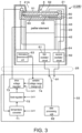
- the TQCM sensor 2B is configured approximately similarly to the CQCM sensor 2A excluding that the heater circuit 41 is not embedded in the sensor substrate 40 but a Peltier element 43 is disposed as a heat regulation mechanism below the sensor substrate 40. 42 in FIG. 3 denotes a spacer.
- the TQCM sensor 2B regulates a voltage of the Peltier element 43 to, for example, a range from -10 to +10 V in an electric potential difference between the positive terminal H+ side and the negative terminal H- side in a state where a coolant containing, for example, water and an antifreeze is flown through the refrigerant supply passage 33 to perform cooling.
- the temperature of the crystal resonator 4 can be regulated to from -80°C to +125°C.
- the device main body 3 includes a cooling base 31 that cools the base 20 and cools the entire CQCM sensor 2A.
- the cooling base 31 internally includes the refrigerant supply passage 33, and the sensing sensor 2 is configured to be cooled by connecting the sensing sensor 2 to the device main body 3 and supplying the cooling medium to the refrigerant supply passage 33.
- the entire CQCM sensor 2A is cooled by supplying the liquid nitrogen to the refrigerant supply passage 33, and the crystal resonator 4 can be cooled to, for example, -190°C.
- a coolant containing water and an antifreeze is flown as the cooling medium through the refrigerant supply passage 33. This ensures cooling the entire TQCM sensor 2B and cooling the crystal resonator 4 to, for example, -10°C.
- the device main body 3 includes the main unit 32.
- the main unit 32 includes a heat regulation mechanism, here, a drive voltage regulator 73 that regulates a voltage (drive voltage) input to the heater circuit 41 or the Peltier element 43 to regulate the temperature of the crystal resonator 4.
- the main unit 32 includes a temperature converter 71 and a heat regulator 72.
- the temperature converter 71 obtains a temperature information value based on the voltage detected by the temperature detector 7.
- the heat regulator 72 regulates the drive voltage output from the drive voltage regulator 73 in accordance with the temperature information value and outputs a heat regulation voltage to regulate the temperature of the crystal resonator 4.
- the temperature converter 71 is configured to receive, for example, a 24-V voltage, and configured to supply a current to the temperature detector 7.
- the temperature detector 7 is configured to have the resistance value that changes depending on the temperature as described above, a current value input from the temperature detector 7 to the temperature converter 71 changes corresponding to the temperature of the crystal resonator 4, and the temperature converter 71 outputs a temperature detection voltage of 0 to 10 V to the heat regulator 72 based on the changed current value.
- the heat regulator 72 receives, for example, a 24-V voltage, and outputs the heat regulation voltage to regulate the drive voltage of the heat regulation mechanism output from a variable regulator 81 described below.
- the heat regulation voltage is regulated using a difference value between the temperature detection voltage input from the temperature converter 71 and a voltage corresponding to a target temperature of the heat regulation mechanism.
- the main unit 32 includes a variable voltage range change unit 74 that regulates a variable range of the drive voltage output from the drive voltage regulator 73 based on a type signal of the sensing sensor 2 output from the information transmission unit 63 disposed to the oscillator circuit board 24.
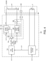
- FIG. 4 illustrates an example in which the CQCM sensor 2A is connected to the device main body 3.
- the drive voltage regulator 73 includes a constant voltage regulator 82 that applies a constant voltage to the heat regulation mechanism, and the variable regulator 81 that varies the voltage input to the heat regulation mechanism (in FIG. 4 , heater circuit 41).
- the constant voltage regulator 82 is configured to apply a 10-V constant voltage to the negative terminal H- side of the heat regulation mechanism in accordance with, for example, the input 24-V voltage.
- the variable regulator 81 is configured to regulate the voltage applied to the positive terminal H+ side of the heat regulation mechanism to, for example, from 0 to 20 V relative to, for example, the input 24-V voltage based on the heat regulation voltage input from an ADJ terminal.
- the variable voltage range change unit 74 includes a switching unit 84 that switches on and off of the constant voltage regulator 82 to switch on and off of the input of the 10-V constant voltage to the negative terminal H- of the heat regulation mechanism.
- the variable voltage range change unit 74 includes an amplifier circuit 83 that changes an amplification factor of the heat regulation voltage input to the ADJ terminal of the variable regulator 81.
- the amplifier circuit 83 is configured as a non-inverting amplifier circuit using an operational amplifier 85, for example, as illustrated in FIG. 5 , and configured to perform a feedback from an output side to a negative input side of the operational amplifier 85 via a resistor R1.
- resistors R2, R3 are disposed in mutually parallel, and on and off of a connection on the resistor R2 side is switched by a switch 86.
- an amplification factor A V of the amplifier circuit is represented by a formula (1) below.
- Amplification Factor A v 1 + R f / R S
- the switch 86 by turning the switch 86 off, Rs increases compared with the case where the switch 86 is on, thereby decreasing the amplification factor of the amplifier circuit 83. Accordingly, the heat regulation voltage is amplified relatively slightly compared with the case where the switch 86 is on, and input to the drive voltage regulator 73. Thus, the regulation range of the drive voltage output from the drive voltage regulator 73 is regulated to, for example, from 0 to 18 V.
- the on and off of the switch 86 of the amplifier circuit 83 and the on and off of the switching unit 84 are switched by a one-bit signal that is transmitted from the information transmission unit 63 and indicates the type information of the heat regulation mechanism.
- the one-bit signal for example, a signal that indicates the type information of the CQCM sensor 2A, switches the switch 86 of the amplifier circuit 83 "off” and switches the switching unit 84 "off.”
- the switch 86 of the amplifier circuit 83 is switched to "on” and the switching unit 84 is switched to "on.”
- the main unit 32 includes a data processing unit 92, and the outputs of the first and the second oscillator circuits 61, 62 described above are input to the data processing unit 92 via a switch 91.
- the data processing unit 92 obtains a frequency of a frequency signal as an input signal, and performs digital processing of the obtained frequency information.
- the data processing unit 92 obtains time-series data of a first oscillation frequency "F1" output from the first oscillator circuit 61 and time-series data of a second oscillation frequency "F2" output from the second oscillator circuit 62.
- the switch 91 is used to perform an intermittent oscillation in which a channel 1 that connects the first oscillator circuit 61 to the data processing unit 92 and a channel 2 that connects the second oscillator circuit 62 to the data processing unit 92 are alternately switched. This avoids an interference between the reaction electrodes 51, 53 and the reference electrodes 52, 54 of the sensing sensor 2 to ensure obtaining the stable frequency signal.
- the frequency signal is, for example, time-divided and retrieved by the data processing unit 92.
- the frequency signal is calculated as, for example, a digital value, and arithmetic processing is performed based on time division data of the calculated digital value.
- the CQCM sensor 2A illustrated in FIG. 2 is used as the sensing sensor 2.
- the CQCM sensor 2A is connected to the main unit 32 via the connector 25.
- an output of the variable regulator 81 of the main unit 32 side is connected to the positive terminal H+ side of the heater circuit 41, and the constant voltage regulator 82 is connected to the negative terminal H- side of the heater circuit 41 via the switching unit 84.
- the temperature detector 7 is connected to the temperature converter 71.
- a one-bit signal informing that the CQCM sensor 2A is connected is input to the main unit 32 side from the information transmission unit 63 provided to the oscillator circuit board 24. Then, the signal input to the main unit 32 is input to the variable voltage range change unit 74, and the switching unit 84 is switched to turn the connection between the constant voltage regulator 82 and the heater circuit 41 off. Accordingly, the input of the 10-V voltage from the constant voltage regulator 82 to the negative side terminal of the heater circuit 41 is cut off. The one-bit signal switches the switch 86 of the amplifier circuit 83 off. This switching decreases the amplification factor of the amplifier circuit 83.
- a heat regulation voltage output from the heat regulator 72 is amplified by the amplifier circuit 83 with the small amplification factor, and input to the ADJ terminal of the variable regulator 81. Therefore, the variable regulator 81 outputs, for example, a voltage of 0 to 18 V based on the heat regulation voltage.
- the drive voltage which is supplied based on the heat regulation voltage and regulated to the range from 0 to 18 V, is applied to the heater circuit 41, and the heat generation temperature is regulated.
- a liquid nitrogen as a cooling medium is flown through the base 20 to cool the crystal resonator 4, and a driving power of the heater circuit 41 is regulated in the range from 0 to 18 V.
- the temperature of the crystal resonator 4 is regulated in a range, for example, from -190°C to 125°C, and measuring the sensing object is performed.
- the gas as the sensing object when a gas as the sensing object is supplied toward the supply port 21A of the CQCM sensor 2A in a state where the CQCM sensor 2A is cooled to -190°C by the liquid nitrogen, the gas as the sensing object is cooled by contacting the reaction electrode 51 exposed on the bottom portion of the supply port 21A, and adsorbs to the reaction electrode 51.
- the switch 91 is switched by time division, and the temperature of the heater circuit 41 is gradually increased at, for example, 1°C/1 minute while measuring the first oscillation frequency F1 and the second oscillation frequency F2 by the data processing unit 92.
- the temperature detector 7 always detects the temperature, and the heating is performed while controlling an amount of the electric power supply supplied from the drive voltage regulator 73 to the heater circuit 41 based on the detected value.
- the data processing unit 92 obtains this timing through an observation of the oscillation frequencies F1, F2, and detects the mass of the sensing object based on the difference between the first oscillation frequency F1 and the second oscillation frequency F2. While the temperature detector 7 always detects the temperature, the temperature at the timing is detected as a sublimation temperature of the sensing object. Based on thus detected sublimation temperature, the type of the sensing object can be identified.
- the TQCM sensor 2B is used for measuring the gas as the sensing object.
- the TQCM sensor 2B is mounted to the device main body 3, and the TQCM sensor 2B is connected to the main unit 32 via the connector 25.
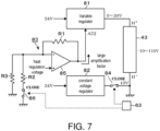
- the constant voltage regulator 82 is connected to the negative terminal H- side of the Peltier element 43 via the switching unit 84, and the variable regulator 81 is connected to positive terminal H+ side of the Peltier element 43 as illustrated in FIG. 7 .
- the temperature detector 7 is connected to the temperature converter 71.
- a one-bit signal informing that the TQCM sensor 2B is connected is input to the main unit 32 from the information transmission unit 63 disposed to the oscillator circuit board 24. Then, the one-bit signal input to the main unit 32 switches the switching unit 84 connected to the constant voltage regulator 82 on. Accordingly, a constant voltage of 10 V is input from the constant voltage regulator 82 to the negative terminal H- side of the Peltier element 43. The one-bit signal input to the main unit 32 switches the switch 86 of the amplifier circuit 83 on. Accordingly, the amplification factor of the amplifier circuit 83 increases compared with the case where the CQCM sensor 2A is connected.
- the heat regulation voltage output from the heat regulator 72 is amplified by the amplifier circuit 83 with the large amplification factor compared with the case where the CQCM sensor 2A is connected, and input to the ADJ terminal of the variable regulator 81. Accordingly, the variable regulator 81 outputs, for example, a voltage in a range from 0 to 20 V, that is, a voltage in a wide range compared with the case where the CQCM sensor 2A is connected, based on the heat regulation voltage.
- the 10-V constant voltage is applied from the constant voltage regulator 82 to the negative terminal H- side of the Peltier element 43.
- the electric potential difference between the positive terminal H+ and the negative terminal H- is regulated to the range from -10 V to +10 V in combination with the range of the drive voltage output from the variable regulator 81 and the drive voltage input from the constant voltage regulator 82, thus regulating the temperature to be output.
- the drive voltage of the Peltier element 43 is regulated to the range from -10 V to +10 V while cooling the base 20 to -10°C by the cooling medium.
- the temperature of the crystal resonator 4 is regulated to a range, for example, from -80°C to 125°C, and measuring the sensing object is performed.
- a gas as the sensing object is supplied toward the supply port 21A of the TQCM sensor 2B, and the crystal resonator 4 is cooled to, for example, -80°C by the Peltier element 43, thereby causing the gas to adsorb to the reaction electrode 51.
- the switch 91 is switched by time division, and the temperature of the Peltier element 43 is gradually increased at, for example, 1°C/1 minute while measuring the first oscillation frequency F1 and the second oscillation frequency F2 by the data processing unit 92.
- the mass of the sensing object is detected, and is detected as the sublimation temperature of the sensing object. Based on thus detected sublimation temperature, the type of the sensing object can be identified.
- the sensing device cools and heats the crystal resonator 4 to cause the sensing object to adsorb and desorb, thereby sensing the sensing object in accordance with the frequency change of the crystal resonator 4 before and after the desorption of the sensing object.
- the drive voltage is regulated to regulate the amplification factor of the heat regulation voltage input to the drive voltage regulator 73 that regulates the temperature of the heat regulation mechanism depending on the type of the sensing sensor 2 connected to the device main body 3.
- the device main body 3 can be standardized between the CQCM sensor 2A and the TQCM sensor 2B.
- the Peltier element 43 applied to the TQCM sensor 2B has a voltage endurance value that differs depending on its working temperature.
- amplifying the heat regulation voltage input to the variable regulator 81 using the amplifier circuit 83 ensures regulating the output voltage range of the variable regulator 81.
- the device main body 3 can be standardized even among a plurality of TQCM sensors 2B that include the respective Peltier elements 43 having the different voltage endurance value.
- the device main body 3 can be standardized even among a plurality of CQCM sensors 2A having different operating temperature ranges of the heater circuit 41.
- the present invention may have a configuration in which on and off of the constant voltage regulator 82 that supplies the constant voltage to the heat regulation mechanism is switched corresponding to the type of the heat regulation mechanism of the sensing sensor 2, thus regulating the range of the voltage supplied to the heat regulation mechanism.
- the output range of the drive voltage output from the drive voltage regulator 73 is preferably switched to more patterns. Therefore, for example, information output from the information transmission unit 63 may be received by a control unit that includes, for example, a CPU and a program, thus switching the output range of the drive voltage output from the drive voltage regulation 73 by the control unit.
- the type information of the heat regulation mechanism of the sensing sensor 2 may be input by the device main body 3 side, and it is only necessary that the switch is switched corresponding to the input type information as described above.
Landscapes
- Physics & Mathematics (AREA)
- Chemical & Material Sciences (AREA)
- General Health & Medical Sciences (AREA)
- Life Sciences & Earth Sciences (AREA)
- Analytical Chemistry (AREA)
- Biochemistry (AREA)
- Health & Medical Sciences (AREA)
- General Physics & Mathematics (AREA)
- Immunology (AREA)
- Pathology (AREA)
- Acoustics & Sound (AREA)
- Dispersion Chemistry (AREA)
- Oscillators With Electromechanical Resonators (AREA)
Claims (4)
- Erfassungsvorrichtung zum Erfassen einer Substanz,
wobei die Erfassungsvorrichtung umfasst:einen Erfassungssensor (2); undeine Haupteinheit (32), wobei der Erfassungssensor (2) so konfiguriert ist, dass er an der Haupteinheit (32) angebracht und von dieser abgenommen werden kann,wobei der Erfassungssensor (2) umfasst:
einen piezoelektrischen Resonator (4), der umfasst:Reaktionselektroden (51, 53), die so konfiguriert sind, dass sie mit der Substanz, die Gas ist, versorgt werden, und die Referenzelektroden (52, 54) so konfiguriert sind, dass sie nicht mit dem Gas versorgt werden;eine erste Oszillatorschaltung (61), die mit den Reaktionselektroden (51, 53) verbunden ist;eine zweite Oszillatorschaltung (62), die mit den Referenzelektroden (52, 54) verbunden ist;einen Wärmeregulationsmechanismus (41, 43), der so konfiguriert ist, dass er eine Temperatur des piezoelektrischen Resonators (4) in Übereinstimmung mit einer Eingangssteuerspannung regelt; undeinen Temperaturdetektor (7), der so konfiguriert ist, dass er die Temperatur des piezoelektrischen Resonators (4) erfasst,wobei der Wärmeregulationsmechanismus (41, 43) eine Heizschaltung (41) oder ein Peltier-Element (43) ist,wobei der Wärmeregulationsmechanismus (41, 43) so konfiguriert ist, dass er den piezoelektrischen Resonator (4) allmählich erwärmt und die Substanz, die an dem piezoelektrischen Resonator (4) adsorbiert ist, sublimiert,wobei die Haupteinheit (32) umfasst:einen Kühlmittelzufuhrdurchgang (33), der so konfiguriert ist, dass er den Erfassungssensor (2) kühlt;eine Datenverarbeitungseinheit (92), die so konfiguriert ist, dass sie eine Oszillationsfrequenzausgabe von der ersten Oszillatorschaltung (61) und eine Oszillationsfrequenzausgabe von der zweiten Oszillatorschaltung (62) beobachtet, um einen Zeitpunkt zu erfassen, zu dem die Oszillationsfrequenz sich signifikant ändert, während der piezoelektrische Resonator (4) durch den Wärmeregulationsmechanismus (41, 43) erwärmt wird,wobei der Zeitpunkt einem Zeitpunkt entspricht, zu dem die Substanz von der Reaktionselektrode (51) desorbiert wird; die Datenverarbeitungseinheit (92) ferner so konfiguriert ist, dass sie die Substanz basierend auf einer Beziehung zwischen einer Änderung der Oszillationsfrequenz des piezoelektrischen Resonators und der detektierten Temperatur erfasst;einen Spannungsregler (73), der einen variablen Regler (81) umfasst, der so konfiguriert ist, dass er eine Ansteuerungsspannung regelt, die einer Wärmeregulierungsspannung entspricht, wobei die Ansteuerungsspannung an den Wärmeregulationsmechanismus (41, 43) ausgegeben wird, wobei die Wärmeregulierungsspannung basierend auf der Temperatur, detektiert von dem Temperaturdetektor (7), eingegeben wird,wobei der Spannungsregler (73) so konfiguriert ist, dass er gemeinsam aus zwei Arten von Erfassungssensoren (2A, 2B) angeordnet ist, die unterschiedliche Arten von Wärmeregulationsmechanismus (41, 43) umfassen, angeordnet werden können; undeine variable Spannungsänderungseinheit (74), die so konfiguriert ist, dass sie die Art des Wärmeregulationsmechanismus (41, 43) detektiert, der an dem Erfassungssensor (2) angeordnet ist, und so konfiguriert ist, dass sie einen variablen Bereich der Ansteuerungsspannung, die von dem Spannungsregler (73) ausgegeben wird, gemäß einer Typinformation des Wärmeregulationsmechanismus (41, 43) regelt. - Erfassungsvorrichtung gemäß Anspruch 1, wobei
die variable Spannungsbereich-Änderungseinheit (74) eine Verstärkerschaltung (83) umfasst, die so konfiguriert ist, dass sie einen Verstärkungsfaktor der Wärmeregulierungsspannung, die in den variablen Regler (81) eingegeben wird, ändert. - Erfassungsvorrichtung gemäß Anspruch 1, wobeider Wärmeregulationsmechanismus (41, 43) umfasst:
die Heizschaltung (41), die eine Wärmeerzeugungstemperatur aufweist, die sich auf der Grundlage einer positiven Ansteuerspannung ändert, oderdas Peltier-Element (43), das so konfiguriert ist, dass es basierend auf einer positiven Ansteuerspannung oder einer negativen Ansteuerspannung Wärme erzeugt oder eine Kühlung durchführt;wobei ein Ausgangsanschluss des variablen Reglers (81) so konfiguriert ist, dass er mit dem positiven Anschluss des Wärmeregulationsmechanismus (41, 43) verbunden werden kann,der Spannungsregler (73) einen konstanten Spannungsregler (82) umfasst, wobei ein Ausgangsanschluss des konstanten Spannungsreglers (82) so konfiguriert ist, dass er mit dem negativen Anschluss des Wärmeregulationsmechanismus (41, 43) verbunden werden kann,die variable Spannungsänderungseinheit (74) eine Schalteinheit (84) umfasst, die so konfiguriert ist, dass der Ausgangsanschluss des konstanten Spannungsreglers (82) von dem negativen Anschluss getrennt wird, wenn die Typinformation des Wärmeregulationsmechanismus die Heizschaltung (41) anzeigt, und mit dem negativen Anschluss verbunden wird, wenn die Typinformation des Wärmeregulationsmechanismus das Peltier-Element (43) anzeigt. - Erfassungsvorrichtung gemäß Anspruch 1, wobei der Erfassungssensor (2) eine Informationsübertragungseinheit (63) umfasst, die so konfiguriert ist, dass sie die Typinformation des Wärmeregulationsmechanismus (41, 43) an die Haupteinheit (32) ausgibt, wenn der Erfassungssensor (2) mit der Haupteinheit (32) verbunden ist.
Applications Claiming Priority (2)
| Application Number | Priority Date | Filing Date | Title |
|---|---|---|---|
| JP2018062542A JP6894397B2 (ja) | 2018-03-28 | 2018-03-28 | 感知装置 |
| PCT/JP2019/012525 WO2019188992A1 (ja) | 2018-03-28 | 2019-03-25 | 感知装置 |
Publications (3)
| Publication Number | Publication Date |
|---|---|
| EP3779401A1 EP3779401A1 (de) | 2021-02-17 |
| EP3779401A4 EP3779401A4 (de) | 2021-12-01 |
| EP3779401B1 true EP3779401B1 (de) | 2025-06-18 |
Family
ID=68058355
Family Applications (1)
| Application Number | Title | Priority Date | Filing Date |
|---|---|---|---|
| EP19777411.0A Active EP3779401B1 (de) | 2018-03-28 | 2019-03-25 | Messvorrichtung |
Country Status (4)
| Country | Link |
|---|---|
| US (1) | US11329210B2 (de) |
| EP (1) | EP3779401B1 (de) |
| JP (1) | JP6894397B2 (de) |
| WO (1) | WO2019188992A1 (de) |
Families Citing this family (7)
| Publication number | Priority date | Publication date | Assignee | Title |
|---|---|---|---|---|
| JP7370915B2 (ja) * | 2020-03-26 | 2023-10-30 | 日本電波工業株式会社 | 感知センサ |
| JP7503481B2 (ja) * | 2020-11-17 | 2024-06-20 | 株式会社アルバック | 膜厚モニタ |
| JP7545904B2 (ja) | 2021-01-27 | 2024-09-05 | 日本電波工業株式会社 | 感知センサ、及び感知装置 |
| US20250087554A1 (en) * | 2023-09-12 | 2025-03-13 | Nxp Usa, Inc. | Thermal apparatus for an integrated circuit and methods of operation |
| JP2025152098A (ja) * | 2024-03-28 | 2025-10-09 | 日本電波工業株式会社 | 感知装置 |
| JP2025151518A (ja) * | 2024-03-28 | 2025-10-09 | 日本電波工業株式会社 | 感知センサモジュール及びセンサモジュール放熱構造 |
| JP2025152577A (ja) * | 2024-03-28 | 2025-10-10 | 日本電波工業株式会社 | 感知センサ |
Family Cites Families (18)
| Publication number | Priority date | Publication date | Assignee | Title |
|---|---|---|---|---|
| US4793182A (en) * | 1987-06-02 | 1988-12-27 | Djorup Robert Sonny | Constant temperature hygrometer |
| JPH05264429A (ja) | 1992-03-16 | 1993-10-12 | Daikin Ind Ltd | 物質検出方法および装置 |
| US6196059B1 (en) * | 1997-08-11 | 2001-03-06 | Fraunhofer Gesellschaft Zur Forderung Der Angewandten Forschung E.V. | Piezoelectric resonator, process for the fabrication thereof including its use as a sensor element for the determination of the concentration of a substance contained in a liquid and/or for the determination of the physical properties of the liquid |
| JP2004245785A (ja) | 2003-02-17 | 2004-09-02 | Seiko Epson Corp | 質量測定用圧電振動子、質量測定装置および質量測定方法 |
| JP2004294356A (ja) * | 2003-03-28 | 2004-10-21 | Citizen Watch Co Ltd | Qcmセンサー装置 |
| JP4594162B2 (ja) * | 2005-05-11 | 2010-12-08 | 日本電波工業株式会社 | 感知装置 |
| JP2011203007A (ja) * | 2010-03-24 | 2011-10-13 | Olympus Corp | 検出センサ、物質検出システム |
| US9086338B2 (en) * | 2010-06-25 | 2015-07-21 | Nihon Dempa Kogyo Co., Ltd. | Sensing device |
| JP2012220454A (ja) * | 2011-04-13 | 2012-11-12 | Olympus Corp | 検出センサ、物質検出システム |
| JP5826557B2 (ja) * | 2011-08-19 | 2015-12-02 | 日本電波工業株式会社 | 感知装置及び感知方法 |
| JP2014197751A (ja) * | 2013-03-29 | 2014-10-16 | セイコーエプソン株式会社 | 発振器、電子機器及び移動体 |
| JP2016186442A (ja) * | 2015-03-27 | 2016-10-27 | 株式会社大真空 | センサ、検出システム及び検出方法 |
| JP6769029B2 (ja) * | 2015-12-14 | 2020-10-14 | セイコーエプソン株式会社 | D/a変換器、回路装置、発振器、電子機器及び移動体 |
| JP6587560B2 (ja) | 2016-02-29 | 2019-10-09 | 日本電波工業株式会社 | 恒温槽付水晶発振器 |
| JP6714235B2 (ja) * | 2016-11-14 | 2020-06-24 | 日本電波工業株式会社 | 物質検出システム及び物質検出方法 |
| JP7214505B2 (ja) * | 2019-02-27 | 2023-01-30 | 日本電波工業株式会社 | 感知センサ |
| JP7246049B2 (ja) * | 2019-05-27 | 2023-03-27 | 日本電波工業株式会社 | 感知装置 |
| CN110514976B (zh) * | 2019-09-29 | 2024-02-13 | 国网江苏省电力有限公司 | 一种gis绝缘缺陷监测装置、系统和检测方法 |
-
2018
- 2018-03-28 JP JP2018062542A patent/JP6894397B2/ja active Active
-
2019
- 2019-03-25 EP EP19777411.0A patent/EP3779401B1/de active Active
- 2019-03-25 WO PCT/JP2019/012525 patent/WO2019188992A1/ja not_active Ceased
- 2019-03-25 US US16/982,031 patent/US11329210B2/en active Active
Also Published As
| Publication number | Publication date |
|---|---|
| US11329210B2 (en) | 2022-05-10 |
| EP3779401A1 (de) | 2021-02-17 |
| US20210104655A1 (en) | 2021-04-08 |
| EP3779401A4 (de) | 2021-12-01 |
| JP6894397B2 (ja) | 2021-06-30 |
| JP2019174269A (ja) | 2019-10-10 |
| WO2019188992A1 (ja) | 2019-10-03 |
Similar Documents
| Publication | Publication Date | Title |
|---|---|---|
| EP3779401B1 (de) | Messvorrichtung | |
| JP5114122B2 (ja) | 恒温槽付水晶発振器における恒温槽の制御回路 | |
| JP5495616B2 (ja) | 熱分析装置 | |
| US11165388B2 (en) | Thermostatic oven type electronic instrument | |
| JP6978638B2 (ja) | ガス検出装置、ガス検出方法及びガス検出装置を備えた装置 | |
| Randjelović et al. | Intelligent thermal vacuum sensors based on multipurpose thermopile MEMS chips | |
| US8596108B2 (en) | Gas measuring device and method of operating the same | |
| JP2012202939A (ja) | ガス検出装置 | |
| US20200296800A1 (en) | Heater temperature control circuit and sensor device using the same | |
| CA2604798A1 (en) | Gas sensor assembly with catalytic element | |
| US11181509B2 (en) | Sensing sensor | |
| US9257993B2 (en) | Control of multi-temperature micro-oven for MEMS devices | |
| US20130042672A1 (en) | Sensing device, sensing system, and sensing method | |
| JP3272633B2 (ja) | 恒温槽型圧電発振器 | |
| US20030052016A1 (en) | Method and system for controlling the temperature of an oxygen sensor | |
| JP2025152103A (ja) | 感知センサ及び感知装置 | |
| JP2006313653A (ja) | ヒータの温度調節装置およびそれを備えた薬剤分包装置 | |
| JP2021156698A (ja) | 感知センサ | |
| JP4385400B2 (ja) | 物理量測定方法および装置 | |
| RU2244936C2 (ru) | Устройство стабилизации температуры микромеханического чувствительного элемента | |
| JP2007285849A (ja) | ガス濃度検出装置 | |
| JP2025152098A (ja) | 感知装置 | |
| JP2008304272A (ja) | ガス濃度検出装置 | |
| RU2280501C1 (ru) | Генератор микропотока паров веществ | |
| JPS6222494A (ja) | 半導体レ−ザ安定装置 |
Legal Events
| Date | Code | Title | Description |
|---|---|---|---|
| STAA | Information on the status of an ep patent application or granted ep patent |
Free format text: STATUS: THE INTERNATIONAL PUBLICATION HAS BEEN MADE |
|
| PUAI | Public reference made under article 153(3) epc to a published international application that has entered the european phase |
Free format text: ORIGINAL CODE: 0009012 |
|
| STAA | Information on the status of an ep patent application or granted ep patent |
Free format text: STATUS: REQUEST FOR EXAMINATION WAS MADE |
|
| 17P | Request for examination filed |
Effective date: 20200916 |
|
| AK | Designated contracting states |
Kind code of ref document: A1 Designated state(s): AL AT BE BG CH CY CZ DE DK EE ES FI FR GB GR HR HU IE IS IT LI LT LU LV MC MK MT NL NO PL PT RO RS SE SI SK SM TR |
|
| AX | Request for extension of the european patent |
Extension state: BA ME |
|
| DAV | Request for validation of the european patent (deleted) | ||
| DAX | Request for extension of the european patent (deleted) | ||
| REG | Reference to a national code |
Ref country code: DE Ref legal event code: R079 Free format text: PREVIOUS MAIN CLASS: G01N0005020000 Ipc: G01N0029020000 Ref country code: DE Ref legal event code: R079 Ref document number: 602019071289 Country of ref document: DE Free format text: PREVIOUS MAIN CLASS: G01N0005020000 Ipc: G01N0029020000 |
|
| A4 | Supplementary search report drawn up and despatched |
Effective date: 20211103 |
|
| RIC1 | Information provided on ipc code assigned before grant |
Ipc: G01N 5/02 20060101ALI20211027BHEP Ipc: G01N 29/02 20060101AFI20211027BHEP |
|
| STAA | Information on the status of an ep patent application or granted ep patent |
Free format text: STATUS: EXAMINATION IS IN PROGRESS |
|
| 17Q | First examination report despatched |
Effective date: 20230802 |
|
| GRAP | Despatch of communication of intention to grant a patent |
Free format text: ORIGINAL CODE: EPIDOSNIGR1 |
|
| STAA | Information on the status of an ep patent application or granted ep patent |
Free format text: STATUS: GRANT OF PATENT IS INTENDED |
|
| INTG | Intention to grant announced |
Effective date: 20250218 |
|
| P01 | Opt-out of the competence of the unified patent court (upc) registered |
Free format text: CASE NUMBER: APP_15715/2025 Effective date: 20250401 |
|
| GRAS | Grant fee paid |
Free format text: ORIGINAL CODE: EPIDOSNIGR3 |
|
| GRAA | (expected) grant |
Free format text: ORIGINAL CODE: 0009210 |
|
| STAA | Information on the status of an ep patent application or granted ep patent |
Free format text: STATUS: THE PATENT HAS BEEN GRANTED |
|
| AK | Designated contracting states |
Kind code of ref document: B1 Designated state(s): AL AT BE BG CH CY CZ DE DK EE ES FI FR GB GR HR HU IE IS IT LI LT LU LV MC MK MT NL NO PL PT RO RS SE SI SK SM TR |
|
| REG | Reference to a national code |
Ref country code: GB Ref legal event code: FG4D |
|
| REG | Reference to a national code |
Ref country code: CH Ref legal event code: EP |
|
| REG | Reference to a national code |
Ref country code: DE Ref legal event code: R096 Ref document number: 602019071289 Country of ref document: DE |
|
| REG | Reference to a national code |
Ref country code: CH Ref legal event code: EP |
|
| REG | Reference to a national code |
Ref country code: IE Ref legal event code: FG4D |
|
| REG | Reference to a national code |
Ref country code: NL Ref legal event code: FP |
|
| PG25 | Lapsed in a contracting state [announced via postgrant information from national office to epo] |
Ref country code: FI Free format text: LAPSE BECAUSE OF FAILURE TO SUBMIT A TRANSLATION OF THE DESCRIPTION OR TO PAY THE FEE WITHIN THE PRESCRIBED TIME-LIMIT Effective date: 20250618 |
|
| REG | Reference to a national code |
Ref country code: LT Ref legal event code: MG9D |
|
| PG25 | Lapsed in a contracting state [announced via postgrant information from national office to epo] |
Ref country code: NO Free format text: LAPSE BECAUSE OF FAILURE TO SUBMIT A TRANSLATION OF THE DESCRIPTION OR TO PAY THE FEE WITHIN THE PRESCRIBED TIME-LIMIT Effective date: 20250918 Ref country code: GR Free format text: LAPSE BECAUSE OF FAILURE TO SUBMIT A TRANSLATION OF THE DESCRIPTION OR TO PAY THE FEE WITHIN THE PRESCRIBED TIME-LIMIT Effective date: 20250919 |
|
| PG25 | Lapsed in a contracting state [announced via postgrant information from national office to epo] |
Ref country code: BG Free format text: LAPSE BECAUSE OF FAILURE TO SUBMIT A TRANSLATION OF THE DESCRIPTION OR TO PAY THE FEE WITHIN THE PRESCRIBED TIME-LIMIT Effective date: 20250618 |
|
| PG25 | Lapsed in a contracting state [announced via postgrant information from national office to epo] |
Ref country code: HR Free format text: LAPSE BECAUSE OF FAILURE TO SUBMIT A TRANSLATION OF THE DESCRIPTION OR TO PAY THE FEE WITHIN THE PRESCRIBED TIME-LIMIT Effective date: 20250618 |
|
| PG25 | Lapsed in a contracting state [announced via postgrant information from national office to epo] |
Ref country code: RS Free format text: LAPSE BECAUSE OF FAILURE TO SUBMIT A TRANSLATION OF THE DESCRIPTION OR TO PAY THE FEE WITHIN THE PRESCRIBED TIME-LIMIT Effective date: 20250918 |
|
| PG25 | Lapsed in a contracting state [announced via postgrant information from national office to epo] |
Ref country code: LV Free format text: LAPSE BECAUSE OF FAILURE TO SUBMIT A TRANSLATION OF THE DESCRIPTION OR TO PAY THE FEE WITHIN THE PRESCRIBED TIME-LIMIT Effective date: 20250618 |
|
| PG25 | Lapsed in a contracting state [announced via postgrant information from national office to epo] |
Ref country code: PT Free format text: LAPSE BECAUSE OF FAILURE TO SUBMIT A TRANSLATION OF THE DESCRIPTION OR TO PAY THE FEE WITHIN THE PRESCRIBED TIME-LIMIT Effective date: 20251020 |
|
| REG | Reference to a national code |
Ref country code: AT Ref legal event code: MK05 Ref document number: 1804599 Country of ref document: AT Kind code of ref document: T Effective date: 20250618 |
|
| PG25 | Lapsed in a contracting state [announced via postgrant information from national office to epo] |
Ref country code: IS Free format text: LAPSE BECAUSE OF FAILURE TO SUBMIT A TRANSLATION OF THE DESCRIPTION OR TO PAY THE FEE WITHIN THE PRESCRIBED TIME-LIMIT Effective date: 20251018 |
|
| PG25 | Lapsed in a contracting state [announced via postgrant information from national office to epo] |
Ref country code: AT Free format text: LAPSE BECAUSE OF FAILURE TO SUBMIT A TRANSLATION OF THE DESCRIPTION OR TO PAY THE FEE WITHIN THE PRESCRIBED TIME-LIMIT Effective date: 20250618 Ref country code: SM Free format text: LAPSE BECAUSE OF FAILURE TO SUBMIT A TRANSLATION OF THE DESCRIPTION OR TO PAY THE FEE WITHIN THE PRESCRIBED TIME-LIMIT Effective date: 20250618 |
|
| PG25 | Lapsed in a contracting state [announced via postgrant information from national office to epo] |
Ref country code: CZ Free format text: LAPSE BECAUSE OF FAILURE TO SUBMIT A TRANSLATION OF THE DESCRIPTION OR TO PAY THE FEE WITHIN THE PRESCRIBED TIME-LIMIT Effective date: 20250618 |
|
| PG25 | Lapsed in a contracting state [announced via postgrant information from national office to epo] |
Ref country code: PL Free format text: LAPSE BECAUSE OF FAILURE TO SUBMIT A TRANSLATION OF THE DESCRIPTION OR TO PAY THE FEE WITHIN THE PRESCRIBED TIME-LIMIT Effective date: 20250618 |
|
| PG25 | Lapsed in a contracting state [announced via postgrant information from national office to epo] |
Ref country code: EE Free format text: LAPSE BECAUSE OF FAILURE TO SUBMIT A TRANSLATION OF THE DESCRIPTION OR TO PAY THE FEE WITHIN THE PRESCRIBED TIME-LIMIT Effective date: 20250618 |
|
| PG25 | Lapsed in a contracting state [announced via postgrant information from national office to epo] |
Ref country code: SK Free format text: LAPSE BECAUSE OF FAILURE TO SUBMIT A TRANSLATION OF THE DESCRIPTION OR TO PAY THE FEE WITHIN THE PRESCRIBED TIME-LIMIT Effective date: 20250618 Ref country code: RO Free format text: LAPSE BECAUSE OF FAILURE TO SUBMIT A TRANSLATION OF THE DESCRIPTION OR TO PAY THE FEE WITHIN THE PRESCRIBED TIME-LIMIT Effective date: 20250618 |
|
| PG25 | Lapsed in a contracting state [announced via postgrant information from national office to epo] |
Ref country code: ES Free format text: LAPSE BECAUSE OF FAILURE TO SUBMIT A TRANSLATION OF THE DESCRIPTION OR TO PAY THE FEE WITHIN THE PRESCRIBED TIME-LIMIT Effective date: 20250618 |
|
| PG25 | Lapsed in a contracting state [announced via postgrant information from national office to epo] |
Ref country code: DK Free format text: LAPSE BECAUSE OF FAILURE TO SUBMIT A TRANSLATION OF THE DESCRIPTION OR TO PAY THE FEE WITHIN THE PRESCRIBED TIME-LIMIT Effective date: 20250618 |
|
| PGFP | Annual fee paid to national office [announced via postgrant information from national office to epo] |
Ref country code: DE Payment date: 20260326 Year of fee payment: 8 |
|
| PG25 | Lapsed in a contracting state [announced via postgrant information from national office to epo] |
Ref country code: IT Free format text: LAPSE BECAUSE OF FAILURE TO SUBMIT A TRANSLATION OF THE DESCRIPTION OR TO PAY THE FEE WITHIN THE PRESCRIBED TIME-LIMIT Effective date: 20250618 |
|
| PGFP | Annual fee paid to national office [announced via postgrant information from national office to epo] |
Ref country code: NL Payment date: 20260310 Year of fee payment: 8 |
|
| PGFP | Annual fee paid to national office [announced via postgrant information from national office to epo] |
Ref country code: FR Payment date: 20260326 Year of fee payment: 8 |
|
| PLBE | No opposition filed within time limit |
Free format text: ORIGINAL CODE: 0009261 |
|
| STAA | Information on the status of an ep patent application or granted ep patent |
Free format text: STATUS: NO OPPOSITION FILED WITHIN TIME LIMIT |
|
| REG | Reference to a national code |
Ref country code: CH Ref legal event code: L10 Free format text: ST27 STATUS EVENT CODE: U-0-0-L10-L00 (AS PROVIDED BY THE NATIONAL OFFICE) Effective date: 20260430 |