EP3778152B1 - Multifunktionaler integrierter arbeitstisch und produktionssystem damit - Google Patents
Multifunktionaler integrierter arbeitstisch und produktionssystem damit Download PDFInfo
- Publication number
- EP3778152B1 EP3778152B1 EP19780655.7A EP19780655A EP3778152B1 EP 3778152 B1 EP3778152 B1 EP 3778152B1 EP 19780655 A EP19780655 A EP 19780655A EP 3778152 B1 EP3778152 B1 EP 3778152B1
- Authority
- EP
- European Patent Office
- Prior art keywords
- robot
- work
- work table
- equipment
- side controller
- Prior art date
- Legal status (The legal status is an assumption and is not a legal conclusion. Google has not performed a legal analysis and makes no representation as to the accuracy of the status listed.)
- Active
Links
Images


Classifications
-
- G—PHYSICS
- G05—CONTROLLING; REGULATING
- G05B—CONTROL OR REGULATING SYSTEMS IN GENERAL; FUNCTIONAL ELEMENTS OF SUCH SYSTEMS; MONITORING OR TESTING ARRANGEMENTS FOR SUCH SYSTEMS OR ELEMENTS
- G05B19/00—Program-control systems
- G05B19/02—Program-control systems electric
- G05B19/418—Total factory control, i.e. centrally controlling a plurality of machines, e.g. direct or distributed numerical control [DNC], flexible manufacturing systems [FMS], integrated manufacturing systems [IMS] or computer integrated manufacturing [CIM]
- G05B19/41815—Total factory control, i.e. centrally controlling a plurality of machines, e.g. direct or distributed numerical control [DNC], flexible manufacturing systems [FMS], integrated manufacturing systems [IMS] or computer integrated manufacturing [CIM] characterised by the cooperation between machine tools, manipulators and conveyor or other workpiece supply system, workcell
- G05B19/4182—Total factory control, i.e. centrally controlling a plurality of machines, e.g. direct or distributed numerical control [DNC], flexible manufacturing systems [FMS], integrated manufacturing systems [IMS] or computer integrated manufacturing [CIM] characterised by the cooperation between machine tools, manipulators and conveyor or other workpiece supply system, workcell manipulators and conveyor only
-
- G—PHYSICS
- G05—CONTROLLING; REGULATING
- G05B—CONTROL OR REGULATING SYSTEMS IN GENERAL; FUNCTIONAL ELEMENTS OF SUCH SYSTEMS; MONITORING OR TESTING ARRANGEMENTS FOR SUCH SYSTEMS OR ELEMENTS
- G05B19/00—Program-control systems
- G05B19/02—Program-control systems electric
- G05B19/418—Total factory control, i.e. centrally controlling a plurality of machines, e.g. direct or distributed numerical control [DNC], flexible manufacturing systems [FMS], integrated manufacturing systems [IMS] or computer integrated manufacturing [CIM]
- G05B19/4189—Total factory control, i.e. centrally controlling a plurality of machines, e.g. direct or distributed numerical control [DNC], flexible manufacturing systems [FMS], integrated manufacturing systems [IMS] or computer integrated manufacturing [CIM] characterised by the transport system
-
- B—PERFORMING OPERATIONS; TRANSPORTING
- B25—HAND TOOLS; PORTABLE POWER-DRIVEN TOOLS; MANIPULATORS
- B25J—MANIPULATORS; CHAMBERS PROVIDED WITH MANIPULATION DEVICES
- B25J13/00—Controls for manipulators
-
- B—PERFORMING OPERATIONS; TRANSPORTING
- B25—HAND TOOLS; PORTABLE POWER-DRIVEN TOOLS; MANIPULATORS
- B25J—MANIPULATORS; CHAMBERS PROVIDED WITH MANIPULATION DEVICES
- B25J5/00—Manipulators mounted on wheels or on carriages
-
- B—PERFORMING OPERATIONS; TRANSPORTING
- B25—HAND TOOLS; PORTABLE POWER-DRIVEN TOOLS; MANIPULATORS
- B25J—MANIPULATORS; CHAMBERS PROVIDED WITH MANIPULATION DEVICES
- B25J5/00—Manipulators mounted on wheels or on carriages
- B25J5/007—Manipulators mounted on wheels or on carriages mounted on wheels
-
- B—PERFORMING OPERATIONS; TRANSPORTING
- B25—HAND TOOLS; PORTABLE POWER-DRIVEN TOOLS; MANIPULATORS
- B25J—MANIPULATORS; CHAMBERS PROVIDED WITH MANIPULATION DEVICES
- B25J9/00—Program-controlled manipulators
- B25J9/16—Program controls
- B25J9/1679—Program controls characterised by the tasks executed
- B25J9/1687—Assembly, peg and hole, palletising, straight line, weaving pattern movement
-
- G—PHYSICS
- G05—CONTROLLING; REGULATING
- G05B—CONTROL OR REGULATING SYSTEMS IN GENERAL; FUNCTIONAL ELEMENTS OF SUCH SYSTEMS; MONITORING OR TESTING ARRANGEMENTS FOR SUCH SYSTEMS OR ELEMENTS
- G05B19/00—Program-control systems
- G05B19/02—Program-control systems electric
- G05B19/418—Total factory control, i.e. centrally controlling a plurality of machines, e.g. direct or distributed numerical control [DNC], flexible manufacturing systems [FMS], integrated manufacturing systems [IMS] or computer integrated manufacturing [CIM]
- G05B19/41865—Total factory control, i.e. centrally controlling a plurality of machines, e.g. direct or distributed numerical control [DNC], flexible manufacturing systems [FMS], integrated manufacturing systems [IMS] or computer integrated manufacturing [CIM] characterised by job scheduling, process planning, material flow
-
- Y—GENERAL TAGGING OF NEW TECHNOLOGICAL DEVELOPMENTS; GENERAL TAGGING OF CROSS-SECTIONAL TECHNOLOGIES SPANNING OVER SEVERAL SECTIONS OF THE IPC; TECHNICAL SUBJECTS COVERED BY FORMER USPC CROSS-REFERENCE ART COLLECTIONS [XRACs] AND DIGESTS
- Y02—TECHNOLOGIES OR APPLICATIONS FOR MITIGATION OR ADAPTATION AGAINST CLIMATE CHANGE
- Y02P—CLIMATE CHANGE MITIGATION TECHNOLOGIES IN THE PRODUCTION OR PROCESSING OF GOODS
- Y02P90/00—Enabling technologies with a potential contribution to greenhouse gas [GHG] emissions mitigation
- Y02P90/02—Total factory control, e.g. smart factories, flexible manufacturing systems [FMS] or integrated manufacturing systems [IMS]
Definitions
- the present invention relates to a multi-function integrated work table on which tasks are performed by a robot and peripheral equipment operating in conjunction with each other, and to a production system using this multi-function integrated work table.
- Robots including articulated arms have been gaining widespread use at manufacturing sites, and the replacement of human labor by robots is in progress for tasks that used to depend on human labor.
- introducing a robot involves not only bearing an introduction cost of the robot itself, but also preparing peripheral devices, including expensive jigs, according to the contents of tasks to construct a new production system that uses the robot, as well as learning how to operate a robot-specific teaching system.
- many users such as companies that do not have a production technology division, small and medium-sized companies, and the like stop short of introducing a robot.
- a robot controller controls a robot body and an automated guided vehicle (AGV) on which the robot body is mounted, as well as work equipment around a work table (on the work table or near the work table).
- AGV automated guided vehicle
- the problem is that connecting a large number of pieces of work equipment leads to a swell in the number of communication and connection means (communication interfaces and communication applications) of the robot controller, because the robot controller should control not only the robot, but also the AGV and work equipment. Therefore, it is desired to establish a more efficient approach to developing and introducing a production system using a robot that solves these problems.
- Patent Literature 1 proposes a system in which a moving robot and a workbench are fixedly connected to each other and electricity and air are supplied from the workbench to the moving robot, and which is connected to a network through the workbench to transmit control information and operation information on the moving robot to the network.
- Patent Literature 2 proposes a system in which a robot feeds and discharges work to and from a machine tool, and in this system, operation of the robot diverges according to the operation state of the machine tool.
- US 5 586 387 A discloses an automated part assembly machine that has a work table supported to a base and movable relative thereto and at least two separate robots each having an end effector movable around within an individual work region.
- the two robots are positioned in such a relation as to give a common work region in which the individual work regions of the two robots overlap.
- a parts supply is arranged to the work table for storing parts to be picked-up by the robots.
- a plurality of operator hands are selectively and removably attached to the end effector of the robot for handling the parts by the robot.
- Disposed within the common region is a jig which positions the parts for assembly by the robot.
- the robots and the work table are controlled to operate in cooperation for assembly of the parts.
- the machine is characterized in that the robots are mounted on the movable work table together with the operator hands and the jig with the robots spaced in the moving direction of the work table, and that the parts supply extends in the moving direction of the work table.
- the robots are enabled to move together with the jig and the operator hands relative to the parts supply so that the robots can reach over a wide range of the parts supply beyond the individual work regions to thereby pick-up suitable parts and transfer them to the jig for immediate assembly of the parts.
- the robot can change the operator hands while moving relative to the parts supply for effecting the part assembly substantially without interruption.
- CN 106 426 228 A discloses a modularized robot teaching system.
- the modularized robot teaching system comprises a workbench, a work target, a modularized robot, a control system and a communication system, wherein the work target, the modularized robot, the control system and the communication system are mounted on the workbench.
- the modularized robot exchanges information with the control system through the communication system and is controlled by the control system, and the work target is mounted on the workbench through a position changing machine.
- a visual angle device used for monitoring the work target is arranged on one side of the position changing machine, and is connected with the control system through the communication system and controlled by the control system.
- the position changing machine is connected with the control system through the communication system and controlled by the control system, wherein the modularized robot is a tandem type modularized robot, mechanical mounting connectors between joints of modules are the same, and thus mutual replacement and free combination between the modules are achieved.
- US 2011/047788 A1 discloses a manufacturing system including an apparatus in which a plurality differently configured workpieces requiring manufacturing operations are processed.
- the apparatus includes a work surface configured to receive apparatus components and a plurality of differently configured workpieces, a tool table adjacent the work surface providing support for tooling and apparatus components required to process various manufacturing operations on the workpieces, and a robotic manipulator positioned adjacent to the work surface and the tool table and having a gripping device configured to grip at least one of the apparatus components.
- the former system can provide scalability by connecting the robot and the work bench to each other.
- the workbench is merely disposed with a connector; actual information processing is undertaken by the robot controller, and no external equipment is disposed or controlled.
- an object of the present invention is to make it possible to easily construct a production system using a robot so that a production system using a robot can be developed and introduced more efficiently.
- the invention introduces a multi-function integrated work table by which a robot and work equipment are combined to construct a production system.
- This multi-function integrated work table allows the robot and the work equipment to operate in conjunction with each other, and simplifies the procedure of construction and reconstruction of a production system associated with arrangement, addition, replacement, change in arrangement, etc. of work equipment.
- a multi-function integrated work table that advantageously solves the above-described problems is as specified in claim 1.
- a production system according to the present invention that advantageously solves the above-described problems is as specified in claim 6.
- the multi-function integrated work table can execute a work process in which a robot near the work table and work equipment on the work table and/or near the work table operate in conjunction with each other, as well as allows a user to easily plan and design this work process, and can thereby simplify the procedure of construction and reconstruction of a production system associated with arrangement, addition, replacement, change in arrangement, etc. of work equipment. It is therefore possible to easily construct a production system using a robot and thereby more efficiently develop and introduce a production system using a robot.
- the production system can execute a work process in which a robot near the work table and work equipment on the work table and/or near the work table operate in conjunction with each other, as well as allows a user to easily plan and design the work process, and can thereby simplify the procedure of construction and reconstruction of a production system associated with arrangement, addition, replacement, change in arrangement, etc. of work equipment. It is therefore possible to easily construct a production system using a robot and thereby more efficiently develop and introduce a production system using a robot.
- At least one of the data tags of the jig and/or the hand tool be a two-dimensional bar code and/or an IC chip.
- the process planning and designing controller be included in the work table, and compile, as robot operation information, a robot operation pattern for the robot to use the work equipment and/or a control pattern of a hand tool attached to the robot, and/or compile an operation pattern of the work equipment as work equipment operation information, and construct a production system by combining the compiled pieces of robot and work equipment operation information.
- the compiled pieces of robot and work equipment operation information be input into and retained by the work table-side controller, and that operation of the robot and operation of the work equipment be controlled by the work table-side controller.
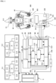
- FIG. 1 is a configuration diagram of one embodiment of a production system according to the present invention using one embodiment of a multi-function integrated work table according to the invention.
- the production system of the one embodiment of the present invention includes a multi-skilled humanoid robot (hereinafter referred to simply as a robot) 1, a robot task integration table (hereinafter referred to as an RIT) 2 as the multi-function integrated work table of the one embodiment of the invention, and a production management system 3 that manages work processes of an entire factory.
- a multi-skilled humanoid robot hereinafter referred to simply as a robot
- RIT robot task integration table
- a production management system 3 that manages work processes of an entire factory.
- the robot 1 has a robot body 15 having a plurality of articulated arms 10, a head 11, and a neck 12 capable of changing the direction of the head, a self-propelled cart 13, and a robot-side controller 14 that controls operation of the robot body 15 and the self-propelled cart 13.
- Each articulated arm 10 has a tool changer 101 to which different hand tools can be attached, an electricity supply mechanism 102 that supplies electricity required for operation of a hand tool, and an air supply mechanism 103 that supplies air required for operation.
- the head 11 has a stereo camera 111, and an imaging direction of the stereo camera 111 can be changed through operation of the neck 12.
- the imaging direction can be desirably changed to at least the two directions of an up-down direction around a predetermined pitch axis and a left-right direction around a predetermined yaw axis.
- the self-propelled cart 13 is desirably an automated guided vehicle (AGV) of simultaneous localization and mapping (SLAM) type that can move the robot 1 to an arbitrary position and in an arbitrary direction.
- the self-propelled cart 13 may have a connecting part 131 for a power source and a connecting part 132 for an air supply source and supply electricity and air to the robot 1. Further, the self-propelled cart 13 may have a battery 133 and charge the battery 133 with electricity supplied from the power source connecting part 131.
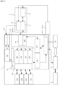
- the RIT 2 has: an RIT-side controller 21 as a table-side controller; a workbench 22; one or more pieces of work equipment 23 disposed on the workbench 22 or in a peripheral part near the workbench 22; a jig placement region 24 and a jig 25 on the workbench 22; a tool hanger 26 that holds a hand tool attached to the tool changer 101 of the robot 1; a hand tool 27; and a position recognition marker 28 of which the robot 1 takes an image by the stereo camera 111 to recognize a relative positional relationship between the robot 1 and the RIT 2.
- a power source 40 and an air supply source 41 for supplying electricity and air to the self-propelled cart 13 may be provided inside the RIT 2.
- the RIT-side controller 21 has: a work equipment interface (hereinafter referred to as a work equipment I/F) 211 as a work equipment communication and connection means for communicating with one or more pieces of work equipment 23; a workbench-top tool interface (hereinafter referred to as a workbench-top tool I/F) 212 for receiving recognition information on a jig, a hand tool, etc.; a robot interface (hereinafter referred to as a robot I/F) 213 as robot communication and connection means for communicating with one or more robots 1; and a production management system interface (hereinafter referred to as a production management system I/F) 214 for communicating with the production management system 3.
- a work equipment interface hereinafter referred to as a work equipment I/F
- a workbench-top tool I/F workbench-top tool I/F
- robot interface hereinafter referred to as a robot I/F
- a production management system interface hereinafter referred to as a production management
- the RIT-side controller 21 is configured using an ordinary computer that has, for example, a central processing unit (CPU), a memory, and an input-output circuit and performs processing, such as control, based on a given program.
- Each of the work equipment I/F 211, the workbench-top tool I/F 212, the robot I/F 213, and the production management system I/F 214 includes a connector for directly connecting a communication line, a radio-wave communication device for wireless connection, or an optical communication device for optical connection, and is formed by a signal conversion circuit board, a signal conversion device, or the like that is used between pieces of equipment or devices that use different communication standards to convert a signal from a communication origin in accordance with the standard that a communication destination uses and transmit the converted signal to the communication destination.
- the RIT-side controller 21 is installed with communication applications for performing identification, state monitoring, and operation control of pieces of work equipment connected to the work equipment I/F 211.
- Equipment types of the pieces of work equipment 23 connected to the work equipment I/F 211 of the RIT 2 are classified by the executable operation and the communication standard, and the communication applications are designed such that each communication application can be used for one equipment type or that the same communication application can be used for a plurality of equipment types. Further, each communication application contains information on the executable operation of the corresponding equipment type.
- the jig placement region 24 and the tool hanger 26 on the workbench 22 are provided with recognition means for recognizing the jig 25 and the hand tool 27 placed therein and thereon.
- recognition means for recognizing the jig 25 and the hand tool 27 placed therein and thereon.
- two-dimensional bar codes or IC tags containing identification information on the jig 25 and the hand tool 27 may be attached to the jig 25 and the hand tool 27, and a reading device of two-dimensional bar codes and IC tags may be provided in the jig placement region 24 and on the tool hanger 26.
- the workbench-top tool I/F 212 of the RIT-side controller 21 is installed with recognition software for receiving recognition information on the jig and the hand tool input from the jig/hand tool recognition means.
- the RIT 2 has a process planning and designing controller 215 that creates a plan of a work process as a human-machine interface (hereinafter referred to as an HM I/F) that can be operated by an operator as a user who constructs a production system.
- the process planning and designing controller 215 is configured using an ordinary computer that has, for example, a central processing unit (CPU), a memory, and an input-output circuit and performs processing, such as control, based on a given program, and is connected to the RIT-side controller 21.
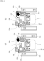
- process planning and designing controller 215 is basically disposed on the side of the RIT 2, in a production system and an RIT 2 of a second embodiment of the present invention in which the robot-side controller 14 is designed to be able to directly connect to the RIT-side controller 21, the process planning and designing controller 215 may be disposed as a robot-side component as shown in FIG. 3 , and in this case, the process planning and designing controller 215 is directly connected to the robot-side controller 14 without the RIT-side robot I/F 213 interposed therebetween.
- the production management system 3 is configured using an ordinary computer that has, for example, a central processing unit (CPU), a memory, and an input-output circuit and performs processing, such as control, based on a given program, and has a production integration management unit 31 that manages production processes of a plurality of RITs 2 disposed inside the factory, an HM I/F 32 formed by an ordinary operation terminal that can be operated by an operator, and an RIT communication unit 311 functioning as an interface for communicating with each RIT 2.
- CPU central processing unit
- memory memory
- an input-output circuit performs processing, such as control, based on a given program
- a production integration management unit 31 that manages production processes of a plurality of RITs 2 disposed inside the factory
- an HM I/F 32 formed by an ordinary operation terminal that can be operated by an operator
- an RIT communication unit 311 functioning as an interface for communicating with each RIT 2.
- the RIT communication unit 311 communicates with the RIT-side controllers 21 of at least an RIT 2 that is used in a process being currently executed, an RIT 201 that is used in a process preceding the process being currently executed, and an RIT 202 that is used in a process succeeding the process being currently executed.
- a user constructs a production system for performing a series of tasks by the following procedure (1) through (12):
- the RIT 2 makes the robot 1 and the work equipment 23 execute tasks by the following procedure (13) through (26):
- the RIT 2 issues a next-process execution command to the robot 1 by the following procedure (27) through (29):
- FIG. 4(a) shows an example of construction of an inspection system using the robots 1 as an example of construction of a production system using the RIT 2.
- This inspection system performs visual inspection and weight inspection on inspection objects, and (30) through (35) below show an example of implementation of a teaching task by the RIT 2:
- the robot task integration table 2 and the production system using this table 2 of the above embodiment make it possible to easily configure and reconfigure a system by simply combining the robot 1 and the work equipment 23 etc. and thus easily construct a production system using a robot. Moreover, it is possible to reduce the man-hours taken for integration of a production system associated with arrangement, connection, etc. of work equipment to a work table that cause an increase in the introduction cost.
- the pieces of work equipment 23 are classified into several equipment types and the RIT-side controller 21 is installed with the communication applications corresponding to the respective equipment types.
- the RIT-side controller 21 is installed with the communication applications corresponding to the respective equipment types.
- the standard for the communication between the robot 1 and the RIT 2 can be simplified by assigning control of the work equipment 23 and process management to the RIT-side controller 21.
- control of the work equipment 23 and process management to the RIT-side controller 21.
- simple communication between devices such as digital input and output suffices as communication between the RIT-side controller 21 and the robot-side controller 14 during execution of a process.
- APIs for operating the pieces of work equipment are automatically provided to the process planning and designing controller even in a case that a new production system with different contents of tasks is configured, and simply combining the robot 1, the work equipment 23, etc. can configure a system, so that a production system using a robot can be easily constructed. Moreover, it is possible to reduce the man-hours taken for integration of a production system associated with arrangement, connection, etc. of work equipment to a work table that causes an increase in the introduction cost.
- the multi-function integrated work table of the invention may include a function that enables a collaborative operation by a human and a robot.
- the multi-function integrated work table may have a laser sensor or a light curtain disposed thereon to detect workers approaching a periphery of the multi-function integrated work table, and may cause the robot to perform deceleration processing, stop processing, or the like for a collaborative operation.
- a collaborative operation can be enabled even when the robot does not have a detection function for a collaborative operation, and the absence of safety fences means greater flexibility in the arrangement layout of the multi-function integrated work table.
- the multi-function integrated work table may send a command to the robot through the production management system that prohibits the robot from entering that region or orders the robot to decelerate, and may warn the worker of the approaching robot.
- the safety of the production system can be enhanced compared with when a moving robot is operated independently.
- a production system may be constructed in which a plurality of robots is disposed near the multi-function integrated work table and these robots operate in a coordinated manner as well as operate in conjunction with work equipment.
- the multi-function integrated work table and the production system using this work table of the present invention can execute a work process in which a robot near the work table and working equipment on the work table and/or near the work table operate in conjunction with each other, as well as allow a user to easily plan and design this work process, and can thereby simplify the procedure of construction and reconstruction of a production system associated with arrangement, addition, replacement, change in arrangement, etc. of work equipment. It is therefore possible to easily construct a production system using a robot and thereby more efficiently develop and introduce a production system using a robot.
Landscapes
- Engineering & Computer Science (AREA)
- General Engineering & Computer Science (AREA)
- Manufacturing & Machinery (AREA)
- Quality & Reliability (AREA)
- Physics & Mathematics (AREA)
- General Physics & Mathematics (AREA)
- Automation & Control Theory (AREA)
- Robotics (AREA)
- Mechanical Engineering (AREA)
- General Factory Administration (AREA)
- Manipulator (AREA)
Claims (12)
- Integrierter Multifunktionsarbeitstisch (2) zum Konfigurieren eines Produktionssystems durch Kombinieren von zumindest einem Roboter (1), der in der Nähe des Arbeitstischs (2) angeordnet ist und eine roboterseitige Steuerung (14) aufweist, und einer Vielzahl von Teilen von Arbeitsausrüstung (23), die auf dem Arbeitstisch (2) oder in der Nähe des Arbeitstischs (2) angeordnet und in einem Arbeitsprozess, der mit dem Roboter (1) durchgeführt wird, verwendet werden, wobei:der Arbeitstisch (2) eine arbeitstischseitige Steuerung (21) umfasst, die kommunikativ mit einer Prozessplanungs- und -gestaltungssteuerung (215), die dazu in der Lage ist, durch einen Benutzer bedient zu werden, verbindbar ist;wobei die arbeitstischseitige Steuerung (21) ein Arbeitsausrüstungskommunikationsund -verbindungsmittel (211), das mit einem oder mehreren Kommunikationsstandards kompatibel und dazu in der Lage ist, mit der Arbeitsausrüstung (23) zu kommunizieren, und ein Roboterkommunikations- und -verbindungsmittel (213) aufweist, das dazu in der Lage ist, mit der roboterseitigen Steuerung (14) zu kommunizieren, und wobei die arbeitstischseitige Steuerung (21) ausgelegt ist, um einen Arbeitsprozess auszuführen, in dem der Roboter (1) und die Arbeitsausrüstung (23) in Verbindung miteinander arbeiten, indem Signale, die Identifikations- und Zustandsüberwachungsinformationen über den Roboter (1) und die Arbeitsausrüstung (23) von der roboterseitigen Steuerung (14) und der Arbeitsausrüstung (23) empfangen werden und dann diese Identifikations- und Zustandsüberwachungssignale an die Prozessplanungs- und -gestaltungssteuerung (215) gesendet werden, und indem ferner Betriebsbefehlssignale an die roboterseitige Steuerung (14) und die Arbeitsausrüstung (23) gemäß dem Arbeitsprozess, in dem der Roboter (1) und die Arbeitsausrüstung (23) in Verbindung miteinander arbeiten, gesendet werden und dann Betriebszustandssignale von der roboterseitigen Steuerung (14) und der Arbeitsausrüstung (23) empfangen werden;wobei die Teile von Arbeitsausrüstung (23) je nach Ausrüstungstyp klassifiziert werden;wobei die arbeitstischseitige Steuerung (21) ein Arbeitsausrüstungskommunikationsund -verbindungsprogramm aufweist, das zumindest einem Ausrüstungstyp entspricht; undwobei, wenn die Teile von Arbeitsausrüstung (23) durch einen Benutzer mit der arbeitstischseitigen Steuerung (21) verbunden werden und den gleichen Ausrüstungstyp aufweisen, das Arbeitsausrüstungskommunikations- und -verbindungsprogramm dann dazu in der Lage ist, mit diesen Teilen von Arbeitsausrüstung (23) durch dasselbe Arbeitsausrüstungskommunikations- und -verbindungsprogramm zu kommunizieren, und wobei die arbeitstischseitige Steuerung (21) das entsprechende Arbeitsausrüstungskommunikations- und -verbindungsprogramm ausführt, um eine Identifikations- und Zustandsüberwachung der verbundenen Teile von Arbeitsausrüstung zu starten, und die Identifikations-, die Zustandsüberwachungsinformationen, Informationen zu Aufgaben, die die Teile von Arbeitsausrüstung ausführen können, und Anwendungsprogrammierungsschnittstellen zum Ausführen dieser Aufgaben an die Prozessplanungs- und -gestaltungssteuerung (215) sendet.
- Integrierter Multifunktionsarbeitstisch (2) nach Anspruch 1, wobei:ein Spannvorrichtungsanordnungsbereich (24), in dem eine Spannvorrichtung (25), die in einem Arbeitsprozess unter Verwendung des Roboters (1) verwendet wird, angeordnet ist und/oder eine Werkzeugaufhängung (26), die ein Handwerkzeug (27) hält, das in einem Arbeitsprozess unter Verwendung des Roboters (1) verwendet wird, auf dem Arbeitstisch (2) angeordnet ist;die Spannvorrichtung (25) und/oder das Handwerkzeug (27) mit einer Datenmarkierung bereitgestellt sind, die Identifikationsinformationen zu der Spannvorrichtung (25) und/oder dem Handwerkzeug (27) enthält;der Arbeitstisch (2) ferner in dem Spannvorrichtungsanordnungsbereich (24) und/oder auf der Werkzeugaufhängung (26) ein Spannvorrichtungs- und/oder Handwerkzeugidentifikationsmittel zum Identifizieren der Spannvorrichtung (25) und/oder des Handwerkzeugs (27) auf dem Arbeitstisch (2) aufweist, indem die Datenmarkierung der Spannvorrichtung (25) und/oder des Handwerkzeugs (27) erkannt wird; unddie arbeitstischseitige Steuerung (21) mit dem Spannvorrichtungs- und/oder Handwerkzeugidentifikationsmittel verbunden ist, um Identifikationsinformationen zu der Spannvorrichtung (25) und/oder dem Handwerkzeug (27) von dem Spannvorrichtungsund/oder Handwerkzeugidentifikationsmittel zu erfassen.
- Integrierter Multifunktionsarbeitstisch (2) nach Anspruch 2, wobei zumindest eine der Datenmarkierungen der Spannvorrichtung (25) und/oder des Handwerkzeugs (27) ein zweidimensionaler Barcode und/oder ein IC-Chip ist.
- Integrierter Multifunktionsarbeitstisch (2) nach Anspruch 2 oder 3, wobei:die arbeitstischseitige Steuerung (21) ein Spannvorrichtungs- und/oder Handwerkzeugerkennungsprogramm aufweist; unddas Spannvorrichtungs- und/oder Handwerkzeugerkennungsprogramm Informationen zu Aufgaben enthält, die der Roboter (1) unter Verwendung einer Spannvorrichtung (25) und/oder eines Handwerkzeugs (27), die auf dem Arbeitstisch (2) angeordnet sind, ausführen kann, und ausgelegt ist, um an der Prozessplanungs- und -gestaltungssteuerung (215) Informationen zu den ausführbaren Aufgaben und Informationen über einen Probebetrieb zum Ausführen dieser Aufgaben zusätzlich zu Identifikationsinformationen auf der Spannvorrichtung (25) und/oder dem Handwerkzeug (27), die auf dem Arbeitstisch (2) angeordnet sind, bereitzustellen.
- Integrierter Multifunktionsarbeitstisch (2) nach einem der Ansprüche 1 bis 4, wobei:die Prozessplanungs- und -gestaltungssteuerung (215) in dem Arbeitstisch (2) beinhaltet ist;die arbeitstischseitige Steuerung (21) und die Prozessplanungs- und - gestaltungssteuerung (215) kommunikativ miteinander verbunden sind; undbasierend auf den Signalen, die die Identifikations- und Zustandsüberwachungsinformationen zu dem Roboter und der Arbeitsausrüstung tragen, die Prozessplanungs- und -gestaltungssteuerung ausgelegt ist, um den Arbeitsprozess, in dem der Roboter und die Arbeitsausrüstung in Verbindung miteinander arbeiten, zu planen und zu gestalten.
- Produktionssystem, das Folgendes umfasst:einen integrierten Multifunktionstisch (2) nach einem der Ansprüche 1 bis 4;den zumindest einen Roboter (1), der in der Nähe des Arbeitstischs (2) angeordnet ist und eine roboterseitige Steuerung (14) aufweist;den zumindest einen Teil von Arbeitsausrüstung (23), die auf dem Arbeitstisch (2) oder in der Nähe des Arbeitstischs (2) angeordnet ist, der mit der arbeitstischseitigen Steuerung (21) basierend auf zumindest einem Kommunikationsstandard verbunden ist, und in einem Arbeitsprozess unter Verwendung des Roboters (1) verwendet wird; unddie Prozessplanungs- und -gestaltungssteuerung (215), wobei die Prozessplanungsund -gestaltungssteuerung (215) in dem Arbeitstisch (2) oder dem Roboter (1) beinhaltet ist; wobei:
basierend auf den Signalen, die die Identifikations- und Zustandsüberwachungsinformationen zu dem Roboter (1) und der Arbeitsausrüstung (23) tragen, die Prozessplanungs- und -gestaltungssteuerung (215) ausgelegt ist, um den Arbeitsprozess, in dem der Roboter (1) und die Arbeitsausrüstung (23) in Verbindung miteinander arbeiten, zu planen und zu gestalten. - Produktionssystem nach Anspruch 6, wobei:der Roboter (1) eine Vielzahl von Gelenkarmen (10), einen Kopf (11), einen Hals (12), der dazu in der Lage ist, eine Haltung des Kopfs (11) zu ändern, und einen selbstangetriebenen Wagen (13) aufweist, der dazu in der Lage ist, den Roboter (1) in eine beliebige Position und eine beliebige Richtung zu bewegen;die roboterseitige Steuerung (14) ausgelegt ist, um den Betrieb des Gelenkarms (10), des Kopfs (11), des Halses (12) und des selbstangetriebenen Wagens (13) zu steuern;der Gelenkarm (10) einen Werkzeugwechsler (101), an dem verschiedene Handwerkzeuge (27) anbringbar sind, und einen Mechanismus (102, 103) aufweist, der Elektrizität und/oder Luft, die für den Betrieb des Handwerkzeugs (27) erforderlich sind, zuführt;der Kopf (11) eine Stereokamera (111) aufweist, und eine Abbildungsrichtung der Stereokamera (111) durch den Betrieb des Halses (12) veränderbar ist;der Arbeitstisch (2) eine Leistungsquelle (40) und/oder eine Luftzufuhrquelle (41) aufweist; undder selbstangetriebene Wagen (13) einen Verbindungsteil (131, 132) aufweist, der getrennt mit dem Arbeitstisch (2) verbunden ist, wenn der Verbindungsteil (131, 132) mit dem Arbeitstisch (2) verbunden ist, Elektrizität und/oder Luft, die von der Leistungsquelle (40) und/oder der Luftzufuhrquelle (41) des Arbeitstischs (2) durch den Verbindungsteil (131, 132) an den Roboter (1) zugeführt werden, und auch eine Batterie (133), die auf dem selbstangetriebenen Wagen (13) angebracht ist, mit Elektrizität geladen ist, die von der Elektrizitätsversorgungsquelle des Arbeitstischs (2) durch den Verbindungsteil (131, 132) zugeführt wurde.
- Produktionssystem nach Anspruch 7, wobei:der Arbeitstisch (2) eine Positionserkennungsmarkierung (28) darauf aufweist, damit der Roboter (1) eine relative Positionsbeziehung zwischen dem Arbeitstisch (2) und dem Roboter (1) erkennt; undwenn der Verbindungsteil (131, 132) des selbstangetriebenen Wagens (13) mit dem Arbeitstisch (2) verbunden ist, der Roboter (1) ausgelegt ist, um ein Bild der Positionserkennungsmarkierung (28) durch die Stereokamera (111) aufzunehmen und ein gemeinsames Koordinatensystem mit dem Arbeitstisch (2) zu teilen.
- Produktionssystem nach einem der Ansprüche 6 bis 8, wobei die Prozessplanungsund -gestaltungssteuerung (215) in dem Arbeitstisch (2) beinhaltet ist und ausgelegt ist, um als Roboterbetriebsinformationen ein Roboterbetriebsmuster für den Roboter (1) zur Verwendung der Arbeitsausrüstung (23) und/oder ein Steuermuster eines Handwerkzeugs (27), das an dem Roboter (1) angebracht ist, zu kompilieren und/oder um ein Betriebsmuster der Arbeitsausrüstung (23) als Arbeitsausrüstungsbetriebsinformationen zu kompilieren, und um ein Produktionssystem durch Kombinieren der kompilierten Teile von Roboter- (1) und Arbeitsausrüstungsbetriebsinformationen zu konstruieren.
- Produktionssystem nach Anspruch 9, wobei:die Prozessplanungs- und -gestaltungssteuerung (215) in dem Arbeitstisch (2) beinhaltet ist;die kompilierten Teile von Roboter- und Arbeitsausrüstungsbetriebsinformationen in die arbeitstischseitige Steuerung (21) eingegeben und davon gehalten werden, undder Betrieb des Roboters (1) und der Betrieb der Arbeitsausrüstung (23) durch die arbeitstischseitige Steuerung (21) gesteuert werden.
- Produktionssystem nach Anspruch 9, wobei:die Prozessplanungs- und -gestaltungssteuerung (215) in dem Roboter (1) beinhaltet ist;die kompilierten Roboterbetriebsinformationen in die roboterseitige Steuerung (14) eingegeben und davon gehalten werden;die kompilierten Arbeitsausrüstungsbetriebsinformationen in die arbeitstischseitige Steuerung (21) eingegeben und davon gehalten werden;der Betrieb des Roboters (1) durch die roboterseitige Steuerung (14) gesteuert wird; undder Betrieb der Arbeitsausrüstung (23) durch die arbeitstischseitige Steuerung (21) gesteuert wird.
- Produktionssystem nach einem der Ansprüche 6 bis 11, wobei:das Produktionssystem ein Produktionsverwaltungssystem (3) umfasst, das eine Prozessverwaltungssteuerung aufweist und ausgelegt ist, um einen Gesamtprozess, einschließlich eines Arbeitsprozesszustands von zumindest einem Prozess, der einem aktuellen Arbeitsprozess vorausgeht, und/oder einen Prozess, der darauf folgt, zu verwalten; unddie arbeitstischseitige Steuerung (21) mit der Prozessverwaltungssteuerung kommuniziert.
Applications Claiming Priority (2)
| Application Number | Priority Date | Filing Date | Title |
|---|---|---|---|
| JP2018073221A JP6644104B2 (ja) | 2018-04-05 | 2018-04-05 | 多機能統合型作業テーブルおよびそれを用いた生産システム |
| PCT/JP2019/015221 WO2019194316A1 (ja) | 2018-04-05 | 2019-04-05 | 多機能統合型作業テーブルおよびそれを用いた生産システム |
Publications (4)
| Publication Number | Publication Date |
|---|---|
| EP3778152A1 EP3778152A1 (de) | 2021-02-17 |
| EP3778152A4 EP3778152A4 (de) | 2021-06-16 |
| EP3778152B1 true EP3778152B1 (de) | 2024-08-07 |
| EP3778152C0 EP3778152C0 (de) | 2024-08-07 |
Family
ID=68100477
Family Applications (1)
| Application Number | Title | Priority Date | Filing Date |
|---|---|---|---|
| EP19780655.7A Active EP3778152B1 (de) | 2018-04-05 | 2019-04-05 | Multifunktionaler integrierter arbeitstisch und produktionssystem damit |
Country Status (4)
| Country | Link |
|---|---|
| US (1) | US12117817B2 (de) |
| EP (1) | EP3778152B1 (de) |
| JP (1) | JP6644104B2 (de) |
| WO (1) | WO2019194316A1 (de) |
Families Citing this family (5)
| Publication number | Priority date | Publication date | Assignee | Title |
|---|---|---|---|---|
| JP7062041B1 (ja) * | 2020-10-19 | 2022-05-02 | カワダロボティクス株式会社 | ピック・アンド・プレース計画策定方法およびピック・アンド・プレースシステム |
| KR20220152790A (ko) * | 2021-05-10 | 2022-11-17 | 삼성전자주식회사 | 전자 장치 및 이의 제어 방법 |
| CN120826300A (zh) * | 2023-03-06 | 2025-10-21 | 软银集团股份有限公司 | 机器人的控制系统、机器人的控制程序和机器人的管理系统 |
| CN219988104U (zh) * | 2023-04-24 | 2023-11-10 | 内蒙古中环晶体材料有限公司 | 一种单晶圆棒的边皮收集系统 |
| JP7453483B1 (ja) * | 2023-04-26 | 2024-03-19 | ファナック株式会社 | データ供給装置、ロボットシステム、データ供給方法、ロボットの制御方法、データ供給プログラムおよび制御プログラム |
Family Cites Families (29)
| Publication number | Priority date | Publication date | Assignee | Title |
|---|---|---|---|---|
| IT1224488B (it) | 1988-10-13 | 1990-10-04 | Olivetti Prodotti Ind Spa | Architettura di un sistema integrato per il controllo di un officina di produzione industriale |
| JPH0538664A (ja) * | 1991-08-02 | 1993-02-19 | Mitsubishi Electric Corp | 機械加工部品生産方法 |
| JPH05158528A (ja) * | 1991-12-02 | 1993-06-25 | Hitachi Ltd | ロボットの制御方式 |
| JP3012463B2 (ja) | 1993-12-22 | 2000-02-21 | 松下電工株式会社 | 組立装置 |
| FI955274A7 (fi) * | 1995-11-03 | 1997-05-04 | Robotic Technology Systems Fin | Työstösolu ja menetelmä kappaleen työstämiseksi |
| JP3643478B2 (ja) * | 1997-05-19 | 2005-04-27 | 株式会社東芝 | 制御システム |
| US6347253B1 (en) | 1998-04-30 | 2002-02-12 | Kabushiki Kaisha Toshiba | Control system for executing a task instruction by performing distributed processing via a number of modules |
| JPH11338509A (ja) * | 1998-05-21 | 1999-12-10 | Central Motor Co Ltd | 生産指示装置及びその生産指示方法 |
| JP3673117B2 (ja) * | 1999-06-14 | 2005-07-20 | 和泉電気株式会社 | 組立装置とそのためのトレイシステム |
| KR20090051029A (ko) | 2006-06-14 | 2009-05-20 | 맥도널드 디트윌러 앤드 어소시에이츠 인코포레이티드 | 직각풀리 구동기구를 갖는 수술조종장치 |
| JP4857242B2 (ja) * | 2007-11-05 | 2012-01-18 | 株式会社日立製作所 | ロボット |
| JP4820395B2 (ja) * | 2008-09-11 | 2011-11-24 | 川田工業株式会社 | ロボットの作業位置修正システムおよびそのシステムを備えた簡易設置型ロボット |
| JP4598865B2 (ja) | 2009-02-17 | 2010-12-15 | ファナック株式会社 | 工作機械と組み合わせて使用するロボットの制御装置 |
| US20110047788A1 (en) | 2009-07-20 | 2011-03-03 | Durr Ecoclean, Inc. | Manufacturing system including modular assembly station for flexible manufacturing and optional automated component part feed system therefor |
| JP5130509B2 (ja) * | 2010-08-11 | 2013-01-30 | 川田工業株式会社 | 作業ロボット用エンドエフェクタ交換装置およびその一部を具える作業ロボット |
| EP2466404A1 (de) * | 2010-12-14 | 2012-06-20 | Abb As | Verfahren zur Steuerung von Industrierobotern in einem Arbeitsbereich |
| US9272423B2 (en) * | 2010-12-22 | 2016-03-01 | Stratom, Inc. | Robotic tool interchange system |
| JP2012218093A (ja) * | 2011-04-06 | 2012-11-12 | Canon Inc | ロボットシステム |
| JP2014144490A (ja) | 2013-01-28 | 2014-08-14 | Seiko Epson Corp | ロボット、およびロボットシステム |
| JP5954274B2 (ja) | 2013-07-26 | 2016-07-20 | 株式会社安川電機 | ロボットシステム |
| US10525603B2 (en) | 2013-08-22 | 2020-01-07 | The Boeing Company | Method and apparatus for exchanging nozzles and tips for a fluid dispensing system |
| JP5863857B2 (ja) | 2014-03-07 | 2016-02-17 | ファナック株式会社 | ワークの供給と排出を行うロボットを制御するロボット制御装置 |
| JP6249292B2 (ja) * | 2014-05-07 | 2017-12-20 | カワダロボティクス株式会社 | 作業システム |
| JP6470763B2 (ja) * | 2014-12-26 | 2019-02-13 | 川崎重工業株式会社 | 生産システム |
| WO2017079344A1 (en) * | 2015-11-02 | 2017-05-11 | The Johns Hopkins University | Generation of robotic user interface responsive to connection of peripherals to robot |
| CN106426228B (zh) * | 2016-09-18 | 2018-09-25 | 柳州铁道职业技术学院 | 模块化机器人教学系统 |
| JP6444971B2 (ja) * | 2016-12-27 | 2018-12-26 | ファナック株式会社 | 作業計画装置 |
| JP6707485B2 (ja) * | 2017-03-22 | 2020-06-10 | 株式会社東芝 | 物体ハンドリング装置およびその較正方法 |
| JP6965716B2 (ja) * | 2017-12-13 | 2021-11-10 | オムロン株式会社 | 工程設計装置、手順生成装置、工程設計装置の制御方法、情報処理プログラム、および、記録媒体 |
-
2018
- 2018-04-05 JP JP2018073221A patent/JP6644104B2/ja active Active
-
2019
- 2019-04-05 US US17/045,466 patent/US12117817B2/en active Active
- 2019-04-05 EP EP19780655.7A patent/EP3778152B1/de active Active
- 2019-04-05 WO PCT/JP2019/015221 patent/WO2019194316A1/ja not_active Ceased
Also Published As
| Publication number | Publication date |
|---|---|
| WO2019194316A1 (ja) | 2019-10-10 |
| JP6644104B2 (ja) | 2020-02-12 |
| EP3778152A4 (de) | 2021-06-16 |
| US12117817B2 (en) | 2024-10-15 |
| EP3778152A1 (de) | 2021-02-17 |
| US20210026335A1 (en) | 2021-01-28 |
| JP2019185258A (ja) | 2019-10-24 |
| EP3778152C0 (de) | 2024-08-07 |
Similar Documents
| Publication | Publication Date | Title |
|---|---|---|
| EP3778152B1 (de) | Multifunktionaler integrierter arbeitstisch und produktionssystem damit | |
| CN102934539B (zh) | 集中控制装置及集中控制方法 | |
| US20210039254A1 (en) | Method for extending end user programming of an industrial robot with third party contributions | |
| US9329593B2 (en) | Robot system, method for controlling robot, and method for producing to-be-processed material | |
| KR20210065865A (ko) | 제어 시스템, 컨트롤러 및 제어 방법 | |
| Ghodsian et al. | Toward designing an integration architecture for a mobile manipulator in production systems: Industry 4.0 | |
| US10099376B2 (en) | Method for setting up and/or calibrating a robot | |
| CN110662698A (zh) | 自动化系统和用于运行自动化系统的方法 | |
| WO2020231319A1 (en) | Robot cell setup system and process | |
| CN110914021A (zh) | 带有用于执行至少一个工作步骤的操纵设备的操纵装置以及方法和计算机程序 | |
| Drouot et al. | A transformable manufacturing concept for low-volume aerospace assembly | |
| EP3700722B1 (de) | Produktionszelle | |
| JP7731996B2 (ja) | ロボットセル | |
| KR20180128359A (ko) | 제어 시스템 및 실장 장치 | |
| Weiss et al. | Identification of industrial robot arm work cell use cases and a test bed to promote monitoring, diagnostic, and prognostic technologies | |
| Merat et al. | Advances in agile manufacturing | |
| JP7739453B2 (ja) | ロボットセル | |
| Makris et al. | Open-Digital-Industrial and Networking pilot lines using modular components for scalable production–ODIN project approach | |
| JP7225452B1 (ja) | 無人搬送装置、及びこれを備えた加工システム | |
| Koekemoer et al. | Development of a reconfigurable pallet system for a robotic cell | |
| EP3988255B1 (de) | Verfahren und montageeinheit zur montage von nicht elektrischen bauteilen auf einem bauteilträger | |
| Thi et al. | Robotic System for Electronic Component Identification Based on Visual Object Localization | |
| Quinn et al. | Advances in Agile Manufacturing | |
| Erkkilä | iCIM–Integration of Mitsubishi RV-6S Industrial Robot and Machine Vision System | |
| EP4074471A1 (de) | Robotische zellen |
Legal Events
| Date | Code | Title | Description |
|---|---|---|---|
| STAA | Information on the status of an ep patent application or granted ep patent |
Free format text: STATUS: THE INTERNATIONAL PUBLICATION HAS BEEN MADE |
|
| PUAI | Public reference made under article 153(3) epc to a published international application that has entered the european phase |
Free format text: ORIGINAL CODE: 0009012 |
|
| STAA | Information on the status of an ep patent application or granted ep patent |
Free format text: STATUS: REQUEST FOR EXAMINATION WAS MADE |
|
| 17P | Request for examination filed |
Effective date: 20201022 |
|
| AK | Designated contracting states |
Kind code of ref document: A1 Designated state(s): AL AT BE BG CH CY CZ DE DK EE ES FI FR GB GR HR HU IE IS IT LI LT LU LV MC MK MT NL NO PL PT RO RS SE SI SK SM TR |
|
| AX | Request for extension of the european patent |
Extension state: BA ME |
|
| A4 | Supplementary search report drawn up and despatched |
Effective date: 20210514 |
|
| RIC1 | Information provided on ipc code assigned before grant |
Ipc: B25J 13/00 20060101AFI20210508BHEP Ipc: B25J 5/00 20060101ALI20210508BHEP Ipc: G05B 19/418 20060101ALI20210508BHEP |
|
| DAV | Request for validation of the european patent (deleted) | ||
| DAX | Request for extension of the european patent (deleted) | ||
| STAA | Information on the status of an ep patent application or granted ep patent |
Free format text: STATUS: EXAMINATION IS IN PROGRESS |
|
| 17Q | First examination report despatched |
Effective date: 20221221 |
|
| GRAP | Despatch of communication of intention to grant a patent |
Free format text: ORIGINAL CODE: EPIDOSNIGR1 |
|
| STAA | Information on the status of an ep patent application or granted ep patent |
Free format text: STATUS: GRANT OF PATENT IS INTENDED |
|
| INTG | Intention to grant announced |
Effective date: 20240313 |
|
| GRAS | Grant fee paid |
Free format text: ORIGINAL CODE: EPIDOSNIGR3 |
|
| GRAA | (expected) grant |
Free format text: ORIGINAL CODE: 0009210 |
|
| STAA | Information on the status of an ep patent application or granted ep patent |
Free format text: STATUS: THE PATENT HAS BEEN GRANTED |
|
| AK | Designated contracting states |
Kind code of ref document: B1 Designated state(s): AL AT BE BG CH CY CZ DE DK EE ES FI FR GB GR HR HU IE IS IT LI LT LU LV MC MK MT NL NO PL PT RO RS SE SI SK SM TR |
|
| REG | Reference to a national code |
Ref country code: GB Ref legal event code: FG4D |
|
| REG | Reference to a national code |
Ref country code: CH Ref legal event code: EP |
|
| REG | Reference to a national code |
Ref country code: IE Ref legal event code: FG4D |
|
| REG | Reference to a national code |
Ref country code: DE Ref legal event code: R096 Ref document number: 602019056633 Country of ref document: DE |
|
| U01 | Request for unitary effect filed |
Effective date: 20240812 |
|
| U07 | Unitary effect registered |
Designated state(s): AT BE BG DE DK EE FI FR IT LT LU LV MT NL PT RO SE SI Effective date: 20240902 |
|
| PG25 | Lapsed in a contracting state [announced via postgrant information from national office to epo] |
Ref country code: NO Free format text: LAPSE BECAUSE OF FAILURE TO SUBMIT A TRANSLATION OF THE DESCRIPTION OR TO PAY THE FEE WITHIN THE PRESCRIBED TIME-LIMIT Effective date: 20241107 |
|
| PG25 | Lapsed in a contracting state [announced via postgrant information from national office to epo] |
Ref country code: PL Free format text: LAPSE BECAUSE OF FAILURE TO SUBMIT A TRANSLATION OF THE DESCRIPTION OR TO PAY THE FEE WITHIN THE PRESCRIBED TIME-LIMIT Effective date: 20240807 Ref country code: GR Free format text: LAPSE BECAUSE OF FAILURE TO SUBMIT A TRANSLATION OF THE DESCRIPTION OR TO PAY THE FEE WITHIN THE PRESCRIBED TIME-LIMIT Effective date: 20241108 |
|
| PG25 | Lapsed in a contracting state [announced via postgrant information from national office to epo] |
Ref country code: IS Free format text: LAPSE BECAUSE OF FAILURE TO SUBMIT A TRANSLATION OF THE DESCRIPTION OR TO PAY THE FEE WITHIN THE PRESCRIBED TIME-LIMIT Effective date: 20241207 |
|
| PG25 | Lapsed in a contracting state [announced via postgrant information from national office to epo] |
Ref country code: HR Free format text: LAPSE BECAUSE OF FAILURE TO SUBMIT A TRANSLATION OF THE DESCRIPTION OR TO PAY THE FEE WITHIN THE PRESCRIBED TIME-LIMIT Effective date: 20240807 |
|
| PG25 | Lapsed in a contracting state [announced via postgrant information from national office to epo] |
Ref country code: RS Free format text: LAPSE BECAUSE OF FAILURE TO SUBMIT A TRANSLATION OF THE DESCRIPTION OR TO PAY THE FEE WITHIN THE PRESCRIBED TIME-LIMIT Effective date: 20241107 Ref country code: ES Free format text: LAPSE BECAUSE OF FAILURE TO SUBMIT A TRANSLATION OF THE DESCRIPTION OR TO PAY THE FEE WITHIN THE PRESCRIBED TIME-LIMIT Effective date: 20240807 |
|
| PG25 | Lapsed in a contracting state [announced via postgrant information from national office to epo] |
Ref country code: RS Free format text: LAPSE BECAUSE OF FAILURE TO SUBMIT A TRANSLATION OF THE DESCRIPTION OR TO PAY THE FEE WITHIN THE PRESCRIBED TIME-LIMIT Effective date: 20241107 Ref country code: PL Free format text: LAPSE BECAUSE OF FAILURE TO SUBMIT A TRANSLATION OF THE DESCRIPTION OR TO PAY THE FEE WITHIN THE PRESCRIBED TIME-LIMIT Effective date: 20240807 Ref country code: NO Free format text: LAPSE BECAUSE OF FAILURE TO SUBMIT A TRANSLATION OF THE DESCRIPTION OR TO PAY THE FEE WITHIN THE PRESCRIBED TIME-LIMIT Effective date: 20241107 Ref country code: IS Free format text: LAPSE BECAUSE OF FAILURE TO SUBMIT A TRANSLATION OF THE DESCRIPTION OR TO PAY THE FEE WITHIN THE PRESCRIBED TIME-LIMIT Effective date: 20241207 Ref country code: HR Free format text: LAPSE BECAUSE OF FAILURE TO SUBMIT A TRANSLATION OF THE DESCRIPTION OR TO PAY THE FEE WITHIN THE PRESCRIBED TIME-LIMIT Effective date: 20240807 Ref country code: GR Free format text: LAPSE BECAUSE OF FAILURE TO SUBMIT A TRANSLATION OF THE DESCRIPTION OR TO PAY THE FEE WITHIN THE PRESCRIBED TIME-LIMIT Effective date: 20241108 Ref country code: ES Free format text: LAPSE BECAUSE OF FAILURE TO SUBMIT A TRANSLATION OF THE DESCRIPTION OR TO PAY THE FEE WITHIN THE PRESCRIBED TIME-LIMIT Effective date: 20240807 |
|
| PG25 | Lapsed in a contracting state [announced via postgrant information from national office to epo] |
Ref country code: SM Free format text: LAPSE BECAUSE OF FAILURE TO SUBMIT A TRANSLATION OF THE DESCRIPTION OR TO PAY THE FEE WITHIN THE PRESCRIBED TIME-LIMIT Effective date: 20240807 |
|
| PG25 | Lapsed in a contracting state [announced via postgrant information from national office to epo] |
Ref country code: CZ Free format text: LAPSE BECAUSE OF FAILURE TO SUBMIT A TRANSLATION OF THE DESCRIPTION OR TO PAY THE FEE WITHIN THE PRESCRIBED TIME-LIMIT Effective date: 20240807 |
|
| PG25 | Lapsed in a contracting state [announced via postgrant information from national office to epo] |
Ref country code: SK Free format text: LAPSE BECAUSE OF FAILURE TO SUBMIT A TRANSLATION OF THE DESCRIPTION OR TO PAY THE FEE WITHIN THE PRESCRIBED TIME-LIMIT Effective date: 20240807 |
|
| U20 | Renewal fee for the european patent with unitary effect paid |
Year of fee payment: 7 Effective date: 20250417 |
|
| PLBE | No opposition filed within time limit |
Free format text: ORIGINAL CODE: 0009261 |
|
| STAA | Information on the status of an ep patent application or granted ep patent |
Free format text: STATUS: NO OPPOSITION FILED WITHIN TIME LIMIT |
|
| 26N | No opposition filed |
Effective date: 20250508 |
|
| PGFP | Annual fee paid to national office [announced via postgrant information from national office to epo] |
Ref country code: CH Payment date: 20250501 Year of fee payment: 7 |
|
| PG25 | Lapsed in a contracting state [announced via postgrant information from national office to epo] |
Ref country code: MC Free format text: LAPSE BECAUSE OF FAILURE TO SUBMIT A TRANSLATION OF THE DESCRIPTION OR TO PAY THE FEE WITHIN THE PRESCRIBED TIME-LIMIT Effective date: 20240807 |
|
| GBPC | Gb: european patent ceased through non-payment of renewal fee |
Effective date: 20250405 |
|
| PG25 | Lapsed in a contracting state [announced via postgrant information from national office to epo] |
Ref country code: GB Free format text: LAPSE BECAUSE OF NON-PAYMENT OF DUE FEES Effective date: 20250405 |
|
| PG25 | Lapsed in a contracting state [announced via postgrant information from national office to epo] |
Ref country code: IE Free format text: LAPSE BECAUSE OF NON-PAYMENT OF DUE FEES Effective date: 20250405 |