EP3988255B1 - Verfahren und montageeinheit zur montage von nicht elektrischen bauteilen auf einem bauteilträger - Google Patents
Verfahren und montageeinheit zur montage von nicht elektrischen bauteilen auf einem bauteilträger Download PDFInfo
- Publication number
- EP3988255B1 EP3988255B1 EP20203916.0A EP20203916A EP3988255B1 EP 3988255 B1 EP3988255 B1 EP 3988255B1 EP 20203916 A EP20203916 A EP 20203916A EP 3988255 B1 EP3988255 B1 EP 3988255B1
- Authority
- EP
- European Patent Office
- Prior art keywords
- machine
- component
- sequences
- movement
- module
- Prior art date
- Legal status (The legal status is an assumption and is not a legal conclusion. Google has not performed a legal analysis and makes no representation as to the accuracy of the status listed.)
- Active
Links
Images


Classifications
-
- B—PERFORMING OPERATIONS; TRANSPORTING
- B25—HAND TOOLS; PORTABLE POWER-DRIVEN TOOLS; MANIPULATORS
- B25J—MANIPULATORS; CHAMBERS PROVIDED WITH MANIPULATION DEVICES
- B25J9/00—Program-controlled manipulators
- B25J9/16—Program controls
- B25J9/1679—Program controls characterised by the tasks executed
- B25J9/1687—Assembly, peg and hole, palletising, straight line, weaving pattern movement
-
- B—PERFORMING OPERATIONS; TRANSPORTING
- B65—CONVEYING; PACKING; STORING; HANDLING THIN OR FILAMENTARY MATERIAL
- B65G—TRANSPORT OR STORAGE DEVICES, e.g. CONVEYORS FOR LOADING OR TIPPING, SHOP CONVEYOR SYSTEMS OR PNEUMATIC TUBE CONVEYORS
- B65G47/00—Article or material-handling devices associated with conveyors; Methods employing such devices
- B65G47/74—Feeding, transfer, or discharging devices of particular kinds or types
- B65G47/90—Devices for picking-up and depositing articles or materials
- B65G47/91—Devices for picking-up and depositing articles or materials incorporating pneumatic, e.g. suction, grippers
- B65G47/917—Devices for picking-up and depositing articles or materials incorporating pneumatic, e.g. suction, grippers control arrangements
-
- B—PERFORMING OPERATIONS; TRANSPORTING
- B25—HAND TOOLS; PORTABLE POWER-DRIVEN TOOLS; MANIPULATORS
- B25J—MANIPULATORS; CHAMBERS PROVIDED WITH MANIPULATION DEVICES
- B25J9/00—Program-controlled manipulators
- B25J9/16—Program controls
- B25J9/1602—Program controls characterised by the control system, structure, architecture
-
- B—PERFORMING OPERATIONS; TRANSPORTING
- B25—HAND TOOLS; PORTABLE POWER-DRIVEN TOOLS; MANIPULATORS
- B25J—MANIPULATORS; CHAMBERS PROVIDED WITH MANIPULATION DEVICES
- B25J9/00—Program-controlled manipulators
- B25J9/16—Program controls
- B25J9/1656—Program controls characterised by programming, planning systems for manipulators
- B25J9/1664—Program controls characterised by programming, planning systems for manipulators characterised by motion, path, trajectory planning
-
- B—PERFORMING OPERATIONS; TRANSPORTING
- B25—HAND TOOLS; PORTABLE POWER-DRIVEN TOOLS; MANIPULATORS
- B25J—MANIPULATORS; CHAMBERS PROVIDED WITH MANIPULATION DEVICES
- B25J9/00—Program-controlled manipulators
- B25J9/16—Program controls
- B25J9/1656—Program controls characterised by programming, planning systems for manipulators
- B25J9/1669—Program controls characterised by programming, planning systems for manipulators characterised by special application, e.g. multi-arm co-operation, assembly, grasping
-
- B—PERFORMING OPERATIONS; TRANSPORTING
- B25—HAND TOOLS; PORTABLE POWER-DRIVEN TOOLS; MANIPULATORS
- B25J—MANIPULATORS; CHAMBERS PROVIDED WITH MANIPULATION DEVICES
- B25J9/00—Program-controlled manipulators
- B25J9/16—Program controls
- B25J9/1674—Program controls characterised by safety, monitoring, diagnostic
- B25J9/1676—Avoiding collision or forbidden zones
-
- B—PERFORMING OPERATIONS; TRANSPORTING
- B25—HAND TOOLS; PORTABLE POWER-DRIVEN TOOLS; MANIPULATORS
- B25J—MANIPULATORS; CHAMBERS PROVIDED WITH MANIPULATION DEVICES
- B25J9/00—Program-controlled manipulators
- B25J9/16—Program controls
- B25J9/1679—Program controls characterised by the tasks executed
- B25J9/1682—Dual arm manipulator; Coordination of several manipulators
-
- G—PHYSICS
- G05—CONTROLLING; REGULATING
- G05B—CONTROL OR REGULATING SYSTEMS IN GENERAL; FUNCTIONAL ELEMENTS OF SUCH SYSTEMS; MONITORING OR TESTING ARRANGEMENTS FOR SUCH SYSTEMS OR ELEMENTS
- G05B19/00—Program-control systems
- G05B19/02—Program-control systems electric
- G05B19/418—Total factory control, i.e. centrally controlling a plurality of machines, e.g. direct or distributed numerical control [DNC], flexible manufacturing systems [FMS], integrated manufacturing systems [IMS] or computer integrated manufacturing [CIM]
- G05B19/41885—Total factory control, i.e. centrally controlling a plurality of machines, e.g. direct or distributed numerical control [DNC], flexible manufacturing systems [FMS], integrated manufacturing systems [IMS] or computer integrated manufacturing [CIM] characterised by modeling, simulation of the manufacturing system
-
- G—PHYSICS
- G05—CONTROLLING; REGULATING
- G05B—CONTROL OR REGULATING SYSTEMS IN GENERAL; FUNCTIONAL ELEMENTS OF SUCH SYSTEMS; MONITORING OR TESTING ARRANGEMENTS FOR SUCH SYSTEMS OR ELEMENTS
- G05B2219/00—Program-control systems
- G05B2219/30—Nc systems
- G05B2219/40—Robotics, robotics mapping to robotics vision
- G05B2219/40053—Pick 3-D object from pile of objects
-
- G—PHYSICS
- G05—CONTROLLING; REGULATING
- G05B—CONTROL OR REGULATING SYSTEMS IN GENERAL; FUNCTIONAL ELEMENTS OF SUCH SYSTEMS; MONITORING OR TESTING ARRANGEMENTS FOR SUCH SYSTEMS OR ELEMENTS
- G05B2219/00—Program-control systems
- G05B2219/30—Nc systems
- G05B2219/45—Nc applications
- G05B2219/45063—Pick and place manipulator
-
- Y—GENERAL TAGGING OF NEW TECHNOLOGICAL DEVELOPMENTS; GENERAL TAGGING OF CROSS-SECTIONAL TECHNOLOGIES SPANNING OVER SEVERAL SECTIONS OF THE IPC; TECHNICAL SUBJECTS COVERED BY FORMER USPC CROSS-REFERENCE ART COLLECTIONS [XRACs] AND DIGESTS
- Y02—TECHNOLOGIES OR APPLICATIONS FOR MITIGATION OR ADAPTATION AGAINST CLIMATE CHANGE
- Y02P—CLIMATE CHANGE MITIGATION TECHNOLOGIES IN THE PRODUCTION OR PROCESSING OF GOODS
- Y02P90/00—Enabling technologies with a potential contribution to greenhouse gas [GHG] emissions mitigation
- Y02P90/02—Total factory control, e.g. smart factories, flexible manufacturing systems [FMS] or integrated manufacturing systems [IMS]
Definitions
- the invention refers to a method for assembling non-electric components onto a component-carrier according to the preamble claim 1 and an assembly unit for assembling non-electric components onto a component-carrier according to the preamble claim 9.
- switch cabinets or control cabinets are custom made for each customer and lot sizes - in the sense of how many identical products are produced in one batch - can be as small as a single panel.
- the robotic devices include robots incorporating two-dimensional, linear motors movable along a stationary platen and coupled to various power sources through flexible, extendible, umbilical cords.
- the robot devices are selectively connectible with manipulators for holding parts to be assembled and/or for performing operations on such parts and/or members to which such parts are mounted.
- the devices are automatically assembled by selecting elements capable of performing the tasks necessary to complete the work request as well as selecting those elements which result in optimization of the assembly time and avoid collisions and cord tangling in moving along the paths traversed by the robot devices during their assembly.
- a multiplicity of assembled robotic devices may perform the tasks associated with the work request under control of an electronic system permitting simultaneous operations while preventing collisions and cord tangling.
- Robotic device assembly, disassembly and job tasks based on work requests can be performed simultaneously in any combination.
- EP 1 537 959 A2 it is known a method and a system for programming an industrial robot for use in connection with off-line programming of an industrial robot, wherein the programming comprises teaching the robot a path having a number of waypoints located on or in the vicinity of at least one object to be processed by the robot.
- the system comprises a tracking system unit, adapted for providing information about the position of a part of the body of an operator pointing by said part at points on or in the vicinity of the object, a visual feed-back unit, generating a visual feed-back to the operator of the position of the point being presently pointed at by said part of the body, in relation to the object, and a storage unit adapted for storing the position of said part of the body as a waypoint upon receiving a recording command.
- a tracking system unit adapted for providing information about the position of a part of the body of an operator pointing by said part at points on or in the vicinity of the object
- a visual feed-back unit generating a visual feed-back to the operator of the position of the point being presently pointed at by said part of the body, in relation to the object
- a storage unit adapted for storing the position of said part of the body as a waypoint upon receiving a recording command.
- the robots and the worktable are controlled to operate in cooperation for assembly of the parts.
- the machine is characterized in that the robots are mounted on the movable worktable together with the operator hands and the jig with the robots spaced in the moving direction of the worktable, and that the parts supply extends in the moving direction of the worktable.
- the robots are enabled to move together with the jig and the operator hands relative to the parts supply so that the robots can reach over a wide range of the parts supply beyond the individual work regions to thereby successfully pick-up suitable parts and transfer them to the jig for immediate assembly of the parts.
- the robot can change the operator hands while moving relative to the parts supply for effecting the part assembly substantially without interruption, in addition to the advantage of enabling one robot to change the operator hand while the other robot is handling the parts.
- the controller receives sensor signals associated with perception of a first real component during an execution of the control application program.
- Activity of a virtual component is simulated.
- the virtual component being a digital twin of a second real component designed for the work environment and absent in the work environment.
- Virtual data is produced in response to the simulated activity of the virtual component.
- a control application module determines parameters for development of the control application program using the sensor signals for the first real component and the virtual data.
- An "augmented reality ⁇ AR>"-display signal for the work environment is rendered and displayed based on a digital representation of the virtual data during an execution of the control application program.
- the advantage of the idea solving the addressed problem (objective of the invention) and summarized above lies in the reduction of setup costs per assembly.
- This cost will be mainly driven by the cost of generating a digital model of the component-carrier, e.g. back panel, design. Since such models are already used today, for manual assembly, the cost of setting up an automated assembly unit will be close to zero using the idea.
- the machine motion generation approach prevents unintended collision of the machine, e.g. the robot or the two robots. On the other hand, it generates intentional contacts to assemble the cite non-electric components onto the component-carrier, e.g. the back panel (cf. claims 3 and 11).
- the machine motion generation is robust to expected disturbances and tolerances.
- the machine on which the primary kinematic machine-movement-sequences and the secondary kinematic machine-movement-sequences are executed, is a single robot, a single gantry, a single delta picker etc. or includes two robots, two gantries, two delta pickers etc., wherein on one the primary kinematic machine-movement-sequences and on the other the secondary kinematic machine-movement-sequences are executed.
- This force feedback could be used advantageously and in particular according to the claims 4 and 12 when at least one other non-electric component is already placed on the component-carrier and is adjacent to the picked non-electric component to be placed.
- connection technology which according to the claims 8 and 16 is preferably based on riveting or screwing, cannot be implemented, are executed with an expanding pendulum motion for a fitting-finding to implement the connection technology.
- the assembly unit is a machine, e.g. a single robot or a pair of robots (cf. claim 5 or 13), including its control software, e.g. the machine control, to automate the assembly of the non-electrical component, e.g. the wiring duct, the DIN-rail, etc. (cf. claims 7 and 15), onto the component-carrier, e.g. the back panel of the switch cabinet or control cabinet (cf. claims 6 and 14).
- the control software e.g. the machine control
- the machine consists preferably - as already stated above - of two kinematic chains, where each is called accordingly as a robot, and could be a robot arm, gantry, delta picker, or any other suitable kinematic.
- One robot places the components onto the back panel. It is equipped with a tool to pick and place wiring ducts and DIN-rails, such tools include grippers and suction grippers.
- the second robot assembles the components to the back plane by placing blind rivets through holes in the components and matching holes in the back panel.
- control software respectively the machine control.
- the control software respectively the machine control contains an internal model of the machine and its environment, the so-called "machine world model”. This model is initialized from the machine configuration file that includes all collision bodies, their relation to each other, and a description of all kinematic elements of the machine.
- the control software respectively the machine control also contains a description of the machine behavior inter alia given or described by the "machine workflow" which is instantiated by the configuration of the component-carrier, e.g. the back panel, as a product.
- this "machine workflow” is the same for all carrier-components or back panels.
- the machine first picks the non-electric component from a known position in its workspace, which could be a magazine, a conveyor belt, an "Automated Guided Vehicle ⁇ AGV>", etc.. Then it interprets the product description of the carrier-component or back panel, e.g. a CAD drawing, to place the non-electric component, e.g. the DIN-rail or wiring duct, onto the carrier-component or back panel.
- each carrier-component or back panel may contain a different number of non-electric components, other non-electric components and they may be placed at different locations. Therefore, the "machine workflow” is adapted to the specific product configuration.
- the machine motions are not pre-programmed but are computed based on the "machine world model”.
- the motion generation component ensures that all motions are collision-free: motion planning algorithms are used to compute motions that do not collide unintentionally with parts of the machine, the surrounding, obstacles, the back panel, or components of the back panel.
- the machine motion generation also generates intentional contact between the non-electric component and the component-carrier. Different motions are generated, e.g. according to the use-case of a pair of robots, for the one robot that places the non-electric component onto the component-carrier and for the other robot carrying put the connection technology, e.g. inserting the rivets.
- the following placing algorithm is used.
- the new non-electric component is placed in an orthogonal movement straight down onto the back panel until a given force is applied.
- the new non-electric component is placed on a free location on the back panel and then slit to the right location, against the other, adjacent, non-electric component, until a given force is applied.
- the new non-electric component is constrained by two other, adjacent, non-electric components then the new non-electric component is placed down at an angle to the back panel and slit towards one of the other, adjacent, non-electric components until a given force is applied and only then the new non-electric component is placed down flat on the back panel.
- the connection technology is used, which is based preferably on riveting or screwing.
- rivets are placed through holes in the new non-electric component and through corresponding holes in the component-carrier. The locations of these holes are specified in the design of the component-carrier. Because of tolerances in the non-electric components, the component-carrier and the placing of the non-electric components, the holes in the non-electric components and the holes in the component-carrier do not always line up.
- FIGURES 1 to 7 show:
- FIGURE 1 shows an assembled back panel BP of a switch panel or control panel SC.
- this back panel BP there are assembled wiring ducts WD and DIN-rails DR.
- these assembled objects are non-electric components CP being assembled onto a component-carrier CPC.
- FIGURE 2 shows - as a demonstration setup - an assembly unit ABU for automated assembling a non-electric component CP onto a component-carrier CP within a workspace of the assembly unit ABU.
- the assembly unit ABU includes for the cited purpose a machine MA, which comprises according to the FIGURE 2 two robot arms RB attached to a worktable WT, and a machine control MAC being connected with the machine MA and thereby with regard to the automated assembly of the non-electric component CP onto the component-carrier CP working technically and functionally together with the machine MA.
- the workspace is a machine workspace MAWS.
- the assembly unit ABU operating in the machine workspace MAWS to assemble - with regard to the FIGURE 1 - in an automated manner the DIN-rail DR and/or the wiring duct WD as the non-electric component CP onto the back panel BP as the component-carrier CPC the back panel BP is arranged on a table surface of the worktable WT and in a working distance of the two robot arms RB.
- the DIN-rail DR and/or the wiring duct WD are placed and connected on the back panel BP. Indeed, they are arranged also on the table surface of the worktable WT, but in an operating neighborhood of the back panel BP and in a picking distance of one of the two robot arms RB which is responsible for picking the DIN-rail DR and/or the wiring duct WD to be placed and connected on to the back panel BP.
- the FIGURE 2 shows further - according to the depicted demonstration setup - that one DIN-rail DR and one wiring duct WD are already placed and connected on the back panel BP. How the DIN-rail DR and the wiring duct WD were mounted on the back panel BP thereby using the depicted the assembly unit ABU including the machine MA in the form of the two robot arms RB and the machine control MAC will be described next according to the FIGURES 3 to 7 .
- FIGURE 3 shows structure and design of the assembly unit ABU including the machine MA and the machine control MAC for assembling - as depicted in the FIGURE 2 - the non-electric component CP, e.g. the DIN-rail DR and/or the wiring duct WD onto the component-carrier CPC, e.g. the back panel BP of the switch cabinet or control cabinet SC.
- the non-electric component CP e.g. the DIN-rail DR and/or the wiring duct WD onto the component-carrier CPC, e.g. the back panel BP of the switch cabinet or control cabinet SC.
- the machine MA which can be designed preferably either as already mentioned as a single robot RB, a single gantry, a single delta picker etc. or alternatively as already mentioned as two robots RB, e.g. the two robot arms according to the FIGURE 2 , two gantries, two delta pickers etc..
- the machine MA is able to carry out two assembly operations AO, so (i) a pick & place operation PPOP picking the non-electric component CP, DR, WD and placing the picked non-electric component CP, DR, WD onto the component-carrier CPC, BP, SC and (ii) a connect operation COP connecting the placed non-electric component CP, DR, WD with the component-carrier CPC, BP, SC by implementing a connection technology.
- a pick & place operation PPOP picking the non-electric component CP, DR, WD and placing the picked non-electric component CP, DR, WD onto the component-carrier CPC, BP, SC
- a connect operation COP connecting the placed non-electric component CP, DR, WD with the component-carrier CPC, BP, SC by implementing a connection technology.
- connection technology for carrying out the connection operation COP is carried out will be described later on in the context of describing FIGURE 6 and 7 .
- the machine MA and the machine control MAC of the assembly unit ABU which work together technically and functionally, form a hybrid, at least reactive and deliberative machine architecture.
- Such a machine architecture is described for example https://en.wikipedia.org/wiki/Robotic_paradigm according to the version from August 29, 2020 and in https://de.wikipedia.org/wiki/Autonomer_mobiler_Roboter according to the version from October 12, 2020.
- a "machine world model”-module MAWM-M being part of the machine control MAC, implements a "machine world model” as a digital twin to formulate correct behavioral sets of the machine MA, so-called machine-behavioral sets, being used during a run-time of the machine MA
- a "machine workflow”-module MAWF-M being also part of the machine control MAC, implements a workflow of the machine MA, a so-called “machine workflow”, by which a piece of machine work to carry out the pick & place operation PPOP and the connect operation COP is passed in series of machine stages from initiation to completion.
- the machine control MAC includes further a "machine motion generation”-module MAMG-M and a “machine motion execution”-module MAME-M.
- the "machine motion generation"-module MAMG-M thereby provides prv a collision-free motion or path planning of the machine MA within the machine workspace MAWS, where according to the FIGURE 2 the non-electric component CP, DR, WD is assembled onto the component-carrier CP, BP, SC, to the "machine motion execution"-module MAME-M.
- machine motion execution-module MAME-M executes exe on the machine MA primary kinematic machine-movement-sequences MAMS k1 to enable the pick & place operation PPOP and secondary kinematic machine-movement-sequences MAMS k2 to enable the connect operation COP.
- the "machine world model”-module MAWM-M is updated upd by the "machine workflow”-module MAWF-M and the “machine motion generation”-module MAMG-M is updated upd and initialized ilz on one hand by the "machine world model”-module MAWM-M and is requested on the other by the "machine workflow”-module MAWF-M.
- the functional unit FTU enables or ensures the execution of the primary kinematic machine-movement-sequences MAMS k1 and the secondary kinematic machine-movement-sequences MAMS k2 via the machine motion generation in such a way that
- the configuration file CFGF configuring the machine MA and the machine workspace MAWS as well as the design of the component-carrier CPC, BP, SC in form of the design data DD are taken from a data repository DRP by PUSH- or PULL-based data transfer.
- FIGURE 4 shows the placement of a picked non-electric component CP, CP A , CP B onto the component-carrier CPC, BP, SC with a force feedback FFB by the assembly unit ABU, depicted in the FIGURE 3 , including the machine MA and the machine control MAC with the "machine world model"-module MAWM-M, the “machine workflow”-module MAWF-M, the “machine motion generation”-module MAMG-M and the “machine motion execution”-module MAME-M forming the functional unit FTU and thereby executing the primary kinematic machine-movement-sequences MAMS k1 and the secondary kinematic machine-movement-sequences MAMS k2 .
- the following placing algorithm by the functional unit FTU executing the primary kinematic machine-movement-sequences MAMS k1 is used.
- the assembly unit ABU including the machine MA and the machine control MAC with the "machine world model”-module MAWM-M, the “machine workflow”-module MAWF-M, the “machine motion generation”-module MAMG-M and the “machine motion execution”-module MAME-M forming the functional unit FTU enable intentional contact between the picked non-electric component CP A and the component-carrier CPC, BP, SC.
- This intentional contact is released preferably due to either the machine motion generation by the "machine motion generation"-module MAMG-M or the machine motion generation executing the primary kinematic machine-movement-sequences MAMS k1 and the secondary kinematic machine-movement-sequences MAMS k2 by the "machine motion generation"-module MAMG-M and the "machine motion execution"-module MAME-M.
- the assembly unit ABU including the machine MA and the machine control MAC with the "machine world model"-module MAWM-M, the "machine workflow”-module MAWF-M, the “machine motion generation”-module MAMG-M and the “machine motion execution”-module MAME-M forming the functional unit FTU execute the primary kinematic machine-movement-sequences MAMS k1 such that those sequences of the primary kinematic machine-movement-sequences MAMS k1 responsible for placing the picked non-electric component CP, CP B onto the component-carrier CPC, BP, SC are executed with the force feedback FFB to place the picked non-electric component CP, CP B .
- FIGURE 5 shows the placement of a picked non-electric component CP, CP C onto the component-carrier CPC, BP, SC with a force feedback FFB by the assembly unit ABU, depicted in the FIGURE 3 , including the machine MA and the machine control MAC with the "machine world model"-module MAWM-M, the “machine workflow”-module MAWF-M, the “machine motion generation”-module MAMG-M and the “machine motion execution”-module MAME-M forming the functional unit FTU and thereby executing the primary kinematic machine-movement-sequences MAMS k1 and the secondary kinematic machine-movement-sequences MAMS k2 .
- the following placing algorithm by the functional unit FTU executing the primary kinematic machine-movement-sequences MAMS k1 is used.
- the picked non-electric component CP C is placed first ("1" in the FIGURE 1 ) down at an angle to the component-carrier CPC, BP, SC against the first other, non-electric component CP X , until the force feedback FFB is applied and then slit towards ("2" in the FIGURE 1 ) the second other, non-electric component CP Y until the force feedback FFB is applied again and only then the picked non-electric component CP C is placed down flat on the component-carrier C
- the assembly unit ABU including the machine MA and the machine control MAC with the "machine world model”-module MAWM-M, the "machine workflow”-module MAWF-M, the “machine motion generation”-module MAMG-M and the “machine motion execution”-module MAME-M forming the functional unit FTU execute the primary kinematic machine-movement-sequences MAMS k1 such that those sequences of the primary kinematic machine-movement-sequences MAMS k1 responsible for placing the picked non-electric component CP, CP C onto the component-carrier CPC, BP, SC are executed with the force feedback FFB to place the picked non-electric component CP, CP C .
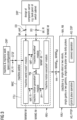
- FIGURE 6 depicts an "ill-fitting"-scenario between a non-electric component CP, placed onto a component-carrier CPC and the component-carrier CPC being connected by a connection technology CT.
- the connection technology CT being used is based preferably on riveting rvt. Alternatively other connect technologies are possible, although they are not depicted, so for instance screwing.
- rivets (cf. FIGURE 7 ) are placed through rivet-holes RH CP , preferably pre-drilled, in the non-electric component CP and through corresponding further rivet-holes RH CPC , also preferably pre-drilled, in the component-carrier CPC.
- the locations of these rivet-holes RH CP , RH CPC are specified in the design of the component-carrier CPC.
- the rivet-holes RH CP in the non-electric component CP and the rivet-holes RH CPC in the component-carrier CPC do not always line up as depicted. The result is an ill-fitting IFG.
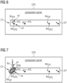
- FIGURE 7 depicts an applied expanding pendulum motion EPM for overcoming the ill-fitting IFG shown in the FIGURE 6 by fitting-finding to implement the connection technology CT.
- the assembly unit ABU including the machine MA and the machine control MAC with the "machine world model"-module MAWM-M, the "machine workflow”-module MAWF-M, the “machine motion generation”-module MAMG-M and the “machine motion execution”-module MAME-M forming the functional unit FTU execute the secondary kinematic machine-movement-sequences MAMS k2 such that those sequences of the secondary kinematic machine-movement-sequences MAMS k2 responsible for connecting the placed non-electric component CPwith the component-carrier CPC, when due to the ill-fitting IFG between the picked and placed non-electric component CP to be connected and the component-carrier CPC the connection technology CT cannot be implemented, are executed with the expanding pendulum motion EPM for a fitting-finding to implement the connection technology CT.
Landscapes
- Engineering & Computer Science (AREA)
- Mechanical Engineering (AREA)
- Robotics (AREA)
- Automation & Control Theory (AREA)
- Automatic Assembly (AREA)
Claims (16)
- Verfahren zur Montage von nicht elektrischen Bauteilen auf einem Bauteilträger, durch das die Montage in zwei Montagevorgänge (AO) aufgeteilt wird:- einen Aufnahme- und Platzierungsvorgang (PPOP): Aufnehmen eines nicht elektrischen Bauteils (CP, CPA, CPB, CPC) und Platzieren des aufgenommenen nicht elektrischen Bauteils (CP, CPA, CPB, CPC) auf den Bauteilträger (CPC, BP, SC) und- einen Verbindungsvorgang (COP): Verbinden des platzierten nicht elektrischen Bauteils (CP, CPA, CPB, CPC) mit dem Bauteilträger (CP, BP, SC) durch Implementieren einer Verbindungstechnologie (CT),die die folgenden Schritte umfasst:a) Ausführen (exe, prv) durch eine Maschinenbewegungserzeugung, die eine kollisionsfreie Bewegung oder eine Wegplanung einer Maschine (MA) innerhalb eines Maschinenarbeitsbereichs (MAWS) beinhaltet, wobei das nicht elektrische Bauteil (CP, CPA, CPB, CPC) auf den Bauteilträger (CP, BP, SC) montiert wird:a1) primäre kinematische Maschinenbewegungssequenzen (MAMSk1), um den Aufnahme- und Platzierungsvorgang (PPOP) zu ermöglichen, unda2) sekundäre kinematische Maschinenbewegungssequenzen (MAMSk2), um den Verbindungsvorgang (COP) zu ermöglichen,b) Bereitstellen einer hybriden, mindestens reaktiven und deliberativen Maschinenarchitektur basierend auf einem "Maschinenweltmodell" als digitaler Zwilling zur Formulierung korrekter Maschinenverhaltenssätze, die während der Maschinenlaufzeit verwendet werden, sowie auf einem "Maschinenarbeitsablauf", gemäß dem ein Maschinenarbeitselement zum Durchführen des Aufnahme- und Platzierungsvorgangs (PPOP) und des Verbindungsvorgangs (COP) in Serien von Maschinenstufen von der Initiierung bis zur Fertigstellung geführt wird, um die Ausführung der primären kinematischen Maschinenbewegungssequenzen (MAMSk1) und der sekundären kinematischen Maschinenbewegungssequenzen (MAMSk2) über die Maschinenbewegungserzeugung zu ermöglichen oder zu gewährleisten, durchb1) Initialisieren (ilz) des "Maschinenweltmodells" gemäß einer Konfigurationsdatei (CFGF), die die Maschine (MA) und den Maschinenarbeitsbereich (MAWS) konfiguriert, undb2) Instanziieren (itt) des "Maschinenarbeitsablaufs" und Aktualisieren (upd) des "Maschinenweltmodells" mit einer Ausgestaltung des Bauteilträgers (CPC, BP, SC), gekennzeichnet durchwobei die Ausführung der primären kinematischen Maschinenbewegungssequenzen (MAMSk1) und der sekundären kinematischen Maschinenbewegungssequenzen (MAMSk2) derart durchgeführt wird, dassc) diejenigen Sequenzen der sekundären kinematischen Bewegungssequenzen (MAMSk2), die das Verbinden des platzierten nicht elektrischen Bauteils (CP, CPA, CPB, CPC) mit dem Bauteilträger (CPC, BP, SC) bewirken, wenn aufgrund einer Fehlpassung (IFG) zwischen dem aufgenommenen und platzierten nicht elektrischen Bauteil (CP, CPA, CPB, CPC), das zu verbinden ist, und dem Bauteilträger (CPC, BP, SC) die Verbindungstechnologie (CT) nicht implementiert werden kann, mit einer sich ausdehnenden Pendelbewegung (EPM) für eine Passungsfindung ausgeführt werden, um die Verbindungstechnologie (CT) zu implementieren.
- Verfahren nach Anspruch 1, dadurch gekennzeichnet, dass die Ausführung der primären kinematischen Maschinenbewegungssequenzen (MAMSk1) und der sekundären kinematischen Maschinenbewegungssequenzen (MAMSk2) derart durchgeführt wird, dass
d) diejenigen Sequenzen der primären kinematischen Maschinenbewegungssequenzen (MAMSk1), die das Platzieren des aufgenommenen nicht elektrischen Bauteils (CP, CPA, CPB, CPC) auf den Bauteilträger (CPC, BP, SC) bewirken, mit Kraftrückkopplung (FFB) ausgeführt werden, um das aufgenommene nicht elektrische Bauteil (CP, CPA, CPB, CPC) zu platzieren. - Verfahren nach Anspruch 1 oder 2, dadurch gekennzeichnet, dass
ein gewollter Kontakt zwischen dem nicht elektrischen Bauteil (CP, CPA, CPB, CPC) und dem Bauteilträger (CPC, BP, SC) durch die Maschinenbewegungserzeugung oder durch die Maschinenbewegungserzeugung, die die primären kinematischen Maschinenbewegungssequenzen (MAMSk1) und die sekundären kinematischen Maschinenbewegungssequenzen (MAMSk2) ausführt, ermöglicht wird. - Verfahren nach Anspruch 1, 2 oder 3, dadurch gekennzeichnet, dass
die Sequenzen der primären kinematischen Maschinenbewegungssequenzen (MAMSk1), die das Platzieren des aufgenommenen nicht elektrischen Bauteils (CP, CPB, CPC) auf den Bauteilträger (CPC, BP, SC) bewirken, mit der Kraftrückkopplung (FFB) ausgeführt werden, wenn mindestens ein weiteres nicht elektrisches Bauteil (CPoth, CPX, CPY) bereits auf dem Bauteilträger (CPC, BP, SC) platziert ist und sich benachbart zu dem aufgenommenen nicht elektrischen Bauteil (CP, CPB, CPC), das zu platzieren ist, befindet. - Verfahren nach einem der Ansprüche 1 bis 4, dadurch gekennzeichnet, dass
die primären kinematischen Maschinenbewegungssequenzen (MAMSk1) und die sekundären kinematischen Maschinenbewegungssequenzen (MAMSk2) entweder auf einem Roboter (RB), einem Portalsystem, einem Delta-Picker usw. oder auf zwei Robotern, zwei Portalsystemen, zwei Delta-Pickern usw. ausgeführt werden, wobei auf einem die primären kinematischen Maschinenbewegungssequenzen (MAMSk1) und auf dem anderen die sekundären kinematischen Maschinenbewegungssequenzen (MAMSk2) ausgeführt werden. - Verfahren nach einem der Ansprüche 1 bis 5, dadurch gekennzeichnet, dass
der Bauteilträger (CPC, BP, SC) eine Rückwand (BP) eines Schaltschranks (SC) ist. - Verfahren nach einem der Ansprüche 1 bis 6, dadurch gekennzeichnet, dass
das nicht elektrische Bauteil (CP, CPA, CPB, CPC) mindestens eines von einer DIN-Schiene (DR) und einem Verdrahtungskanal (WD) ist. - Verfahren nach einem der Ansprüche 1 bis 7, dadurch gekennzeichnet, dass
die Verbindungstechnologie (CT) auf Nieten (rvt) oder Verschrauben basiert. - Montageeinheit (ABU) zur Montage von nicht elektrischen Bauteilen auf einem Bauteilträger, durch die die Montage in zwei Montagevorgänge (AO) aufgeteilt wird:- einen Aufnahme- und Platzierungsvorgang (PPOP), der dazu konfiguriert ist, ein nicht elektrisches Bauteil (CP, CPA, CPB, CPC) aufzunehmen und das aufgenommene nicht elektrische Bauteil (CP, CPA, CPB, CPC) auf den Bauteilträger (CPC, BP, SC) zu platzieren, und- einen Verbindungsvorgang (COP), der dazu konfiguriert ist, das platzierte nicht elektrische Bauteil (CP, CPA, CPB, CPC) mit dem Bauteilträger (CPC, BP, SC) durch Implementieren einer Verbindungstechnologie (CT) zu verbinden, wobei die Montageeinheit (ABU) Folgendes umfasst:
eine Maschine (MA) und eine Maschinensteuerung (MAC), die technisch und funktional zusammenwirken und derart ausgestaltet sind, dassa) die Maschine (MA) und die Maschinensteuerung (MAC) eine hybride, mindestens reaktive und deliberative Maschinenarchitektur mit einem "Maschinenweltmodell"-Modul (MAWM-M) der Maschinensteuerung (MAC) bilden, das dazu konfiguriert ist, ein "Maschinenweltmodell" als digitalen Zwilling zu implementieren, der dazu konfiguriert ist, korrekte Maschinenverhaltenssätze zu formulieren, die während der Maschinenlaufzeit verwendet werden, und einem "Maschinenarbeitsablauf"-Modul (MAWF-M) der Maschinensteuerung (MAC), das dazu konfiguriert ist, einen "Maschinenarbeitsablauf" zu implementieren, gemäß dem ein Maschinenarbeitselement zum Durchführen des Aufnahme- und Platzierungsvorgangs (PPOP) und des Verbindungsvorgangs (COP) in Serien von Maschinenstufen von der Initiierung bis zur Fertigstellung geführt wird,b) die Maschinensteuerung (MAC) ferner ein "Maschinenbewegungserzeugungs"-Modul (MAMG-M) und ein "Maschinenbewegungsausführungs"-Modul (MAME-M) beinhaltet, wobei das "Maschinenbewegungserzeugungs"-Modul (MAMG-M) eine kollisionsfreie Bewegung oder eine Wegplanung der Maschine (MA) innerhalb eines Maschinenarbeitsbereichs (MAWS) bereitstellt (prv), wobei das nicht elektrische Bauteil (CP, CPA, CPB, CPC) auf den Bauteilträger (CP, BP, SC) zu dem "Maschinenbewegungsausführungs"-Modul (MAME-M) montiert wird, das dazu konfiguriert ist, Folgendes auf der Maschine (MA) auszuführen (exe):b1) primäre kinematische Maschinenbewegungssequenzen (MAMSk1), die dazu konfiguriert sind, den Aufnahme- und Platzierungsvorgang (PPOP) zu ermöglichen, undb2) sekundäre kinematische Maschinenbewegungssequenzen (MAMSk2), die dazu konfiguriert sind, den Verbindungsvorgang (COP) zu ermöglichen,c) das "Maschinenweltmodell"-Modul (MAWM-M), das "Maschinenarbeitsablauf"-Modul (MAWF-M), das "Maschinenbewegungserzeugungs"-Modul (MAMG-M) und das "Maschinenbewegungsausführungs"-Modul (MAME-M) innerhalb der Maschinensteuerung (MAC) eine Funktionseinheit (FTU) derart bilden, dass- wenn eine Konfigurationsdatei (CFGF) zur Konfiguration der Maschine (MA) und des Maschinenarbeitsbereichs (MAWS) in das "Maschinenweltmodell"-Modul (MAWM-M) der Maschinensteuerung (MAC) eingegeben (ipt) und dadurch das "Maschinenweltmodell" initialisiert (ilz) wird und- wenn eine Ausgestaltung des Bauteilträgers (CPC, BP, SC) in Form von Ausgestaltungsdaten (DD) dazu konfiguriert sind, in das "Maschinenarbeitsablauf"-Modul (MAWF-M) der Maschinensteuerung (MAC) eingegeben zu werden, das dadurch dazu verwendet wird, den "Maschinenarbeitsablauf" zu instanziieren (itt), und dazu konfiguriert sind, in das "Maschinenweltmodell"-Modul (MAWM-M) eingegeben (ipt) zu werden, das dadurch dazu verwendet wird, das "Maschinenweltmodell" zu aktualisieren (upd), die Ausführung der primären kinematischen Maschinenbewegungssequenzen (MAMSk1) und der sekundären kinematischen Maschinenbewegungssequenzen (MAMSk2) über die Maschinenbewegungserzeugung ermöglicht oder gewährleistet wird,gekennzeichnet durch
wobei die Maschine (MA) und die Maschinensteuerung (MAC) mit dem "Maschinenweltmodell"-Modul (MAWM-M), dem "Maschinenarbeitsablauf"-Modul (MAWF-M), dem "Maschinenbewegungserzeugungs"-Modul (MAMG-M) und dem "Maschinenbewegungsausführungs"-Modul (MAME-M), die die Funktionseinheit (FTU) bilden, dazu ausgestaltet sind, die Ausführung der primären kinematischen Maschinenbewegungssequenzen (MAMSk1) und der sekundären kinematischen Maschinenbewegungssequenzen (MAMSk2) derart durchzuführen, dasse) diejenigen Sequenzen der sekundären kinematischen Bewegungssequenzen (MAMSk2), die das Verbinden des platzierten nicht elektrischen Bauteils (CP, CPA, CPB, CPC) mit dem Bauteilträger (CPC, BP, SC) bewirken, wenn aufgrund einer Fehlpassung (IFG) zwischen dem aufgenommenen und platzierten nicht elektrischen Bauteil (CP, CPA, CPB, CPC), das zu verbinden ist, und dem Bauteilträger (CPC, BP, SC) die Verbindungstechnologie (CT) nicht implementiert werden kann, mit einer sich ausdehnenden Pendelbewegung (EPM) für eine Passungsfindung ausgeführt werden, um die Verbindungstechnologie (CT) zu implementieren. - Montageeinheit (ABU) nach Anspruch 9, dadurch gekennzeichnet, dassdie Maschine (MA) und die Maschinensteuerung (MAC) mit dem "Maschinenweltmodell"-Modul (MAWM-M), dem "Maschinenarbeitsablauf"-Modul (MAWF-M), dem "Maschinenbewegungserzeugungs"-Modul (MAMG-M) und dem "Maschinenbewegungsausführungs"-Modul (MAME-M), die die Funktionseinheit (FTU) bilden, dazu ausgestaltet sind und die Ausführung der primären kinematischen Maschinenbewegungssequenzen (MAMSk1) und der sekundären kinematischen Maschinenbewegungssequenzen (MAMSk2) derart durchführen, dasse) diejenigen Sequenzen der primären kinematischen Maschinenbewegungssequenzen (MAMSk1), die das Platzieren des aufgenommenen nicht elektrischen Bauteils (CP, CPA, CPB, CPC) auf den Bauteilträger (CPC, BP, SC) bewirken, mit Kraftrückkopplung (FFB) ausgeführt werden, um das aufgenommene nicht elektrische Bauteil (CP, CPA, CPB, CPC) zu platzieren.
- Montageeinheit (ABU) nach Anspruch 9 oder 10, dadurch gekennzeichnet, dass
die Maschine (MA) und die Maschinensteuerung (MAC) mit dem "Maschinenweltmodell"-Modul (MAWM-M), dem "Maschinenarbeitsablauf"-Modul (MAWF-M), dem "Maschinenbewegungserzeugungs"-Modul (MAMG-M) und dem "Maschinenbewegungsausführungs"-Modul (MAME-M), die die Funktionseinheit (FTU) bilden, so ausgestaltet sind, dass ein gewollter Kontakt zwischen dem nicht elektrischen Bauteil (CP, CPA, CPB, CPC) und dem Bauteilträger (CPC, BP, SC) ermöglicht wird, insbesondere entweder aufgrund der Maschinenbewegungserzeugung durch das "Maschinenbewegungserzeugungs"-Modul (MAMG-M) oder der Maschinenbewegungserzeugung, die die primären kinematischen Maschinenbewegungssequenzen (MAMSk1) und die sekundären kinematischen Maschinenbewegungssequenzen (MAMSk2) durch das "Maschinenbewegungserzeugungs"-Modul (MAMG-M) und das "Maschinenbewegungsausführungs"-Modul (MAME-M) ausführt. - Montageeinheit (ABU) nach Anspruch 9, 10 oder 11, dadurch gekennzeichnet, dass
die Maschine (MA) und die Maschinensteuerung (MAC) mit dem "Maschinenweltmodell"-Modul (MAWM-M), dem "Maschinenarbeitsablauf"-Modul (MAWF-M), dem "Maschinenbewegungserzeugungs"-Modul (MAMG-M) und dem "Maschinenbewegungsausführungs"-Modul (MAME-M), die die Funktionseinheit (FTU) bilden, derart ausgestaltet sind, dass die Sequenzen der primären kinematischen Maschinenbewegungssequenzen (MAMSk1), die das Platzieren des aufgenommenen nicht elektrischen Bauteils (CP, CPB, CPC) auf den Bauteilträger (CPC, BP, SC) bewirken, mit der Kraftrückkopplung (FFB) ausgeführt werden, wenn mindestens ein weiteres nicht elektrisches Bauteil (CPoth, CPX, CPY) bereits auf dem Bauteilträger (CPC) platziert ist und sich benachbart zu dem aufgenommenen nicht elektrischen Bauteil (CP, CPB, CPC), das zu platzieren ist, befindet. - Montageeinheit (ABU) nach einem der Ansprüche 9 bis 12, dadurch gekennzeichnet, dass
die Maschine (MA), auf der die primären kinematischen Maschinenbewegungssequenzen (MAMSk1) und die sekundären kinematischen Maschinenbewegungssequenzen (MAMSk2) ausgeführt werden, ein einzelner Roboter (RB), ein einzelnes Portalsystem, ein einzelner Delta-Picker usw. ist oder zwei Roboter (RB), zwei Portalsysteme, zwei Delta-Picker usw. beinhaltet, wobei auf einem die primären kinematischen Maschinenbewegungssequenzen (MAMSk1) und auf dem anderen die sekundären kinematischen Maschinenbewegungssequenzen (MAMSk2) ausgeführt werden. - Montageeinheit (ABU) nach einem der Ansprüche 9 bis 13, dadurch gekennzeichnet, dass
der Bauteilträger (CPC, BP, SC) eine Rückwand (BP) eines Schaltschranks (SC) ist. - Montageeinheit (ABU) nach einem der Ansprüche 9 bis 14, dadurch gekennzeichnet, dass
das nicht elektrische Bauteil (CP, CPA, CPB, CPC) mindestens eines von einer DIN-Schiene (DR) und einem Verdrahtungskanal (WD) ist. - Montageeinheit (ABU) nach einem der Ansprüche 9 bis 15, dadurch gekennzeichnet, dass
die Verbindungstechnologie (CT) auf Nieten (rvt) oder Verschrauben basiert.
Priority Applications (3)
| Application Number | Priority Date | Filing Date | Title |
|---|---|---|---|
| EP20203916.0A EP3988255B1 (de) | 2020-10-26 | 2020-10-26 | Verfahren und montageeinheit zur montage von nicht elektrischen bauteilen auf einem bauteilträger |
| US17/500,153 US12037207B2 (en) | 2020-10-26 | 2021-10-13 | Method and assembly unit for assembling non-electric components onto a component carrier |
| CN202111247820.7A CN114474038B (zh) | 2020-10-26 | 2021-10-26 | 用于将非电气组件组装到组件载体上的方法和组装单元 |
Applications Claiming Priority (1)
| Application Number | Priority Date | Filing Date | Title |
|---|---|---|---|
| EP20203916.0A EP3988255B1 (de) | 2020-10-26 | 2020-10-26 | Verfahren und montageeinheit zur montage von nicht elektrischen bauteilen auf einem bauteilträger |
Publications (3)
| Publication Number | Publication Date |
|---|---|
| EP3988255A1 EP3988255A1 (de) | 2022-04-27 |
| EP3988255B1 true EP3988255B1 (de) | 2025-05-21 |
| EP3988255C0 EP3988255C0 (de) | 2025-05-21 |
Family
ID=73020110
Family Applications (1)
| Application Number | Title | Priority Date | Filing Date |
|---|---|---|---|
| EP20203916.0A Active EP3988255B1 (de) | 2020-10-26 | 2020-10-26 | Verfahren und montageeinheit zur montage von nicht elektrischen bauteilen auf einem bauteilträger |
Country Status (3)
| Country | Link |
|---|---|
| US (1) | US12037207B2 (de) |
| EP (1) | EP3988255B1 (de) |
| CN (1) | CN114474038B (de) |
Family Cites Families (21)
| Publication number | Priority date | Publication date | Assignee | Title |
|---|---|---|---|---|
| US4890241A (en) * | 1987-10-26 | 1989-12-26 | Megamation Incorporated | Robotic system |
| JP3012463B2 (ja) | 1993-12-22 | 2000-02-21 | 松下電工株式会社 | 組立装置 |
| US20020165637A1 (en) | 2001-05-07 | 2002-11-07 | Kelly Dillon | Method for highly automated manufacture of metal parts |
| US7457698B2 (en) * | 2001-08-31 | 2008-11-25 | The Board Of Regents Of The University And Community College System On Behalf Of The University Of Nevada, Reno | Coordinated joint motion control system |
| SE526119C2 (sv) * | 2003-11-24 | 2005-07-05 | Abb Research Ltd | Metod och system för programmering av en industrirobot |
| SE0402721D0 (sv) * | 2004-11-05 | 2004-11-05 | Abb Technology Ltd | Mounting system and method |
| ES2331290B1 (es) | 2008-06-27 | 2010-09-29 | Airbus Operations, S.L. | Dispositivo multifuncion y procedimiento de remachado automatico por control numerico. |
| CH707625A1 (de) | 2013-02-28 | 2014-08-29 | Designery Sa | Montagesystem. |
| US9346160B2 (en) | 2013-06-24 | 2016-05-24 | Redwood Robotics, Inc. | Modular reconfigurable workcell for quick connection of peripherals |
| CN106002967B (zh) | 2015-03-31 | 2019-03-22 | 佳能株式会社 | 自动装配方法和自动装配设备 |
| US10155314B2 (en) * | 2015-05-07 | 2018-12-18 | Massachusetts Institute Of Technology | Self-assembling assemblers and manipulators built from a set of primitive blocks |
| DE102016212694A1 (de) | 2016-05-31 | 2017-11-30 | Siemens Aktiengesellschaft | Verfahren zur Orientierung eines Industrieroboters und Industrieroboter |
| US10782668B2 (en) * | 2017-03-16 | 2020-09-22 | Siemens Aktiengesellschaft | Development of control applications in augmented reality environment |
| US10394246B2 (en) * | 2017-03-31 | 2019-08-27 | Neato Robotics, Inc. | Robot with automatic styles |
| WO2018210404A1 (en) * | 2017-05-16 | 2018-11-22 | Abb Schweiz Ag | Method and control system for controlling movement sequences of a robot |
| US11273553B2 (en) * | 2017-06-05 | 2022-03-15 | Autodesk, Inc. | Adapting simulation data to real-world conditions encountered by physical processes |
| DE102017128295A1 (de) | 2017-11-29 | 2019-05-29 | Rittal Gmbh & Co. Kg | Verfahren für die elektrische Verkabelung elektronischer Komponenten im Schaltanlagenbau und eine entsprechende Anordnung |
| AU2019215098A1 (en) | 2018-02-05 | 2020-08-27 | Advanced Solutions Life Sciences, Llc | System and workstation for the design, fabrication and assembly of 3-dimensional constructs |
| CN110561450B (zh) | 2019-08-30 | 2021-09-07 | 哈尔滨工业大学(深圳) | 一种基于动捕的机器人装配离线示例学习系统和方法 |
| CN110561430B (zh) | 2019-08-30 | 2021-08-10 | 哈尔滨工业大学(深圳) | 用于离线示例学习的机器人装配轨迹优化方法及装置 |
| CN111515961B (zh) | 2020-06-02 | 2022-06-21 | 南京大学 | 一种适用于移动机械臂的强化学习奖励方法 |
-
2020
- 2020-10-26 EP EP20203916.0A patent/EP3988255B1/de active Active
-
2021
- 2021-10-13 US US17/500,153 patent/US12037207B2/en active Active
- 2021-10-26 CN CN202111247820.7A patent/CN114474038B/zh active Active
Non-Patent Citations (4)
| Title |
|---|
| BOLOTNIKOVA ANASTASIA ET AL: "A circuit-breaker use-case operated by a humanoid in aircraft manufacturing", 2017 13TH IEEE CONFERENCE ON AUTOMATION SCIENCE AND ENGINEERING (CASE), 1 August 2017 (2017-08-01), pages 15 - 22, XP093091405, ISBN: 978-1-5090-6781-7, Retrieved from the Internet <URL:https://hal.science/hal-01565060v1/file/CASE17_0096_FI.pdf> [retrieved on 20231013], DOI: 10.1109/COASE.2017.8256069 * |
| GIORDANO P.R. ET AL: "Robotic assembly of complex planar parts: An experimental evaluation", 2008 IEEE/RSJ INTERNATIONAL CONFERENCE ON INTELLIGENT ROBOTS AND SYSTEMS, 1 September 2008 (2008-09-01), pages 3775 - 3782, XP093091421, ISSN: 2153-0858, ISBN: 978-1-4244-2057-5, Retrieved from the Internet <URL:https://ieeexplore.ieee.org/stampPDF/getPDF.jsp?tp=&arnumber=4650984&ref=> [retrieved on 20231013], DOI: 10.1109/IROS.2008.4650984 * |
| KHEDDAR ABDERRAHMANE ET AL: "Humanoid Robots in Aircraft Manufacturing: The Airbus Use Cases", IEEE ROBOTICS & AUTOMATION MAGAZINE, IEEE SERVICE CENTER, PISCATAWAY, NJ, US, vol. 26, no. 4, 1 December 2019 (2019-12-01), pages 30 - 45, XP011760161, ISSN: 1070-9932, [retrieved on 20191210], DOI: 10.1109/MRA.2019.2943395 * |
| STASSE OLIVIER ET AL: "TALOS: A new humanoid research platform targeted for industrial applications", 8 March 2017 (2017-03-08), XP093091418, Retrieved from the Internet <URL:https://hal.science/hal-01485519v1/file/iros-talos.pdf> [retrieved on 20231013] * |
Also Published As
| Publication number | Publication date |
|---|---|
| US12037207B2 (en) | 2024-07-16 |
| EP3988255C0 (de) | 2025-05-21 |
| CN114474038B (zh) | 2024-08-13 |
| EP3988255A1 (de) | 2022-04-27 |
| CN114474038A (zh) | 2022-05-13 |
| US20220127085A1 (en) | 2022-04-28 |
Similar Documents
| Publication | Publication Date | Title |
|---|---|---|
| US11986962B2 (en) | Method for extending end user programming of an industrial robot with third party contributions | |
| US9840008B2 (en) | Robot system control method and robot system | |
| JP2023025294A (ja) | オンデマンド遠隔操作を備えた自律ロボット | |
| DK2285537T3 (en) | Device and method for computer-assisted generation of a manipulatorbane | |
| EP2939798A1 (de) | Automatisierungssystem und verfahren zur versorgung eines produktionssystems | |
| US20230099602A1 (en) | Device control based on execution command and updated environment information | |
| Ramasubramanian et al. | Operator-mobile robot collaboration for synchronized part movement | |
| Andersen et al. | Definition and initial case-based evaluation of hardware-independent robot skills for industrial robotic co-workers | |
| EP3778152B1 (de) | Multifunktionaler integrierter arbeitstisch und produktionssystem damit | |
| KR20200038468A (ko) | 로봇을 구비한 취급 장치, 방법 및 컴퓨터 프로그램 | |
| CN103403637B (zh) | 用于教导机器人移动的系统 | |
| Rückert et al. | Augmented Reality for teaching collaborative robots based on a physical simulation | |
| JP6991722B2 (ja) | 独立な自動化システムを協調する方法および装置 | |
| Nevliudov et al. | Multithreaded software control of industrial manipulator movement | |
| EP3988255B1 (de) | Verfahren und montageeinheit zur montage von nicht elektrischen bauteilen auf einem bauteilträger | |
| Stopp et al. | The manufacturing assistant: Safe, interactive teaching of operation sequences | |
| Coiffet et al. | Man-Robot Cooperation: Toward an Advanced Teleoperation Mode | |
| US20250128415A1 (en) | Method and System for Generating a Path for a Robot Arm and a Tool Attached to the Robot Arm | |
| US8588981B2 (en) | System of manipulators and method for controlling such a system | |
| Deisenroth et al. | On-line programming | |
| IT202100001268A1 (it) | Sistema e metodo di configurazione e programmazione di una cella robotica | |
| De Luca | Industrial Robotics | |
| Bujnarowski et al. | and Operation in Confined Spaces | |
| Schafrik | Alpha Foundation for the Improvement of Mine Safety and Health | |
| JP2026510795A (ja) | 人間型ロボットインターフェースおよびワークフロー |
Legal Events
| Date | Code | Title | Description |
|---|---|---|---|
| PUAI | Public reference made under article 153(3) epc to a published international application that has entered the european phase |
Free format text: ORIGINAL CODE: 0009012 |
|
| STAA | Information on the status of an ep patent application or granted ep patent |
Free format text: STATUS: THE APPLICATION HAS BEEN PUBLISHED |
|
| AK | Designated contracting states |
Kind code of ref document: A1 Designated state(s): AL AT BE BG CH CY CZ DE DK EE ES FI FR GB GR HR HU IE IS IT LI LT LU LV MC MK MT NL NO PL PT RO RS SE SI SK SM TR |
|
| STAA | Information on the status of an ep patent application or granted ep patent |
Free format text: STATUS: REQUEST FOR EXAMINATION WAS MADE |
|
| 17P | Request for examination filed |
Effective date: 20220919 |
|
| RBV | Designated contracting states (corrected) |
Designated state(s): AL AT BE BG CH CY CZ DE DK EE ES FI FR GB GR HR HU IE IS IT LI LT LU LV MC MK MT NL NO PL PT RO RS SE SI SK SM TR |
|
| STAA | Information on the status of an ep patent application or granted ep patent |
Free format text: STATUS: EXAMINATION IS IN PROGRESS |
|
| RIC1 | Information provided on ipc code assigned before grant |
Ipc: G05B 19/418 20060101ALI20230919BHEP Ipc: B25J 9/16 20060101AFI20230919BHEP |
|
| 17Q | First examination report despatched |
Effective date: 20231019 |
|
| GRAP | Despatch of communication of intention to grant a patent |
Free format text: ORIGINAL CODE: EPIDOSNIGR1 |
|
| STAA | Information on the status of an ep patent application or granted ep patent |
Free format text: STATUS: GRANT OF PATENT IS INTENDED |
|
| INTG | Intention to grant announced |
Effective date: 20250128 |
|
| GRAS | Grant fee paid |
Free format text: ORIGINAL CODE: EPIDOSNIGR3 |
|
| GRAA | (expected) grant |
Free format text: ORIGINAL CODE: 0009210 |
|
| STAA | Information on the status of an ep patent application or granted ep patent |
Free format text: STATUS: THE PATENT HAS BEEN GRANTED |
|
| AK | Designated contracting states |
Kind code of ref document: B1 Designated state(s): AL AT BE BG CH CY CZ DE DK EE ES FI FR GB GR HR HU IE IS IT LI LT LU LV MC MK MT NL NO PL PT RO RS SE SI SK SM TR |
|
| REG | Reference to a national code |
Ref country code: GB Ref legal event code: FG4D |
|
| REG | Reference to a national code |
Ref country code: CH Ref legal event code: EP |
|
| REG | Reference to a national code |
Ref country code: DE Ref legal event code: R096 Ref document number: 602020051526 Country of ref document: DE |
|
| REG | Reference to a national code |
Ref country code: IE Ref legal event code: FG4D |
|
| U01 | Request for unitary effect filed |
Effective date: 20250521 |
|
| U07 | Unitary effect registered |
Designated state(s): AT BE BG DE DK EE FI FR IT LT LU LV MT NL PT RO SE SI Effective date: 20250527 |
|
| PG25 | Lapsed in a contracting state [announced via postgrant information from national office to epo] |
Ref country code: ES Free format text: LAPSE BECAUSE OF FAILURE TO SUBMIT A TRANSLATION OF THE DESCRIPTION OR TO PAY THE FEE WITHIN THE PRESCRIBED TIME-LIMIT Effective date: 20250521 |
|
| PG25 | Lapsed in a contracting state [announced via postgrant information from national office to epo] |
Ref country code: GR Free format text: LAPSE BECAUSE OF FAILURE TO SUBMIT A TRANSLATION OF THE DESCRIPTION OR TO PAY THE FEE WITHIN THE PRESCRIBED TIME-LIMIT Effective date: 20250822 Ref country code: NO Free format text: LAPSE BECAUSE OF FAILURE TO SUBMIT A TRANSLATION OF THE DESCRIPTION OR TO PAY THE FEE WITHIN THE PRESCRIBED TIME-LIMIT Effective date: 20250821 |
|
| PG25 | Lapsed in a contracting state [announced via postgrant information from national office to epo] |
Ref country code: PL Free format text: LAPSE BECAUSE OF FAILURE TO SUBMIT A TRANSLATION OF THE DESCRIPTION OR TO PAY THE FEE WITHIN THE PRESCRIBED TIME-LIMIT Effective date: 20250521 |
|
| PG25 | Lapsed in a contracting state [announced via postgrant information from national office to epo] |
Ref country code: HR Free format text: LAPSE BECAUSE OF FAILURE TO SUBMIT A TRANSLATION OF THE DESCRIPTION OR TO PAY THE FEE WITHIN THE PRESCRIBED TIME-LIMIT Effective date: 20250521 |
|
| PG25 | Lapsed in a contracting state [announced via postgrant information from national office to epo] |
Ref country code: RS Free format text: LAPSE BECAUSE OF FAILURE TO SUBMIT A TRANSLATION OF THE DESCRIPTION OR TO PAY THE FEE WITHIN THE PRESCRIBED TIME-LIMIT Effective date: 20250821 |
|
| PG25 | Lapsed in a contracting state [announced via postgrant information from national office to epo] |
Ref country code: IS Free format text: LAPSE BECAUSE OF FAILURE TO SUBMIT A TRANSLATION OF THE DESCRIPTION OR TO PAY THE FEE WITHIN THE PRESCRIBED TIME-LIMIT Effective date: 20250921 |
|
| U20 | Renewal fee for the european patent with unitary effect paid |
Year of fee payment: 6 Effective date: 20251020 |
|
| PG25 | Lapsed in a contracting state [announced via postgrant information from national office to epo] |
Ref country code: SM Free format text: LAPSE BECAUSE OF FAILURE TO SUBMIT A TRANSLATION OF THE DESCRIPTION OR TO PAY THE FEE WITHIN THE PRESCRIBED TIME-LIMIT Effective date: 20250521 |
|
| PG25 | Lapsed in a contracting state [announced via postgrant information from national office to epo] |
Ref country code: CZ Free format text: LAPSE BECAUSE OF FAILURE TO SUBMIT A TRANSLATION OF THE DESCRIPTION OR TO PAY THE FEE WITHIN THE PRESCRIBED TIME-LIMIT Effective date: 20250521 |
|
| PG25 | Lapsed in a contracting state [announced via postgrant information from national office to epo] |
Ref country code: SK Free format text: LAPSE BECAUSE OF FAILURE TO SUBMIT A TRANSLATION OF THE DESCRIPTION OR TO PAY THE FEE WITHIN THE PRESCRIBED TIME-LIMIT Effective date: 20250521 |
|
| PLBE | No opposition filed within time limit |
Free format text: ORIGINAL CODE: 0009261 |
|
| STAA | Information on the status of an ep patent application or granted ep patent |
Free format text: STATUS: NO OPPOSITION FILED WITHIN TIME LIMIT |
|
| REG | Reference to a national code |
Ref country code: CH Ref legal event code: L10 Free format text: ST27 STATUS EVENT CODE: U-0-0-L10-L00 (AS PROVIDED BY THE NATIONAL OFFICE) Effective date: 20260402 |