EP3774510B1 - Bike-sensor-vorrichtung - Google Patents
Bike-sensor-vorrichtung Download PDFInfo
- Publication number
- EP3774510B1 EP3774510B1 EP19805562.6A EP19805562A EP3774510B1 EP 3774510 B1 EP3774510 B1 EP 3774510B1 EP 19805562 A EP19805562 A EP 19805562A EP 3774510 B1 EP3774510 B1 EP 3774510B1
- Authority
- EP
- European Patent Office
- Prior art keywords
- sensor
- bike
- frame
- mount
- sensor device
- Prior art date
- Legal status (The legal status is an assumption and is not a legal conclusion. Google has not performed a legal analysis and makes no representation as to the accuracy of the status listed.)
- Active
Links
Images


Classifications
-
- B—PERFORMING OPERATIONS; TRANSPORTING
- B62—LAND VEHICLES FOR TRAVELLING OTHERWISE THAN ON RAILS
- B62K—CYCLES; CYCLE FRAMES; CYCLE STEERING DEVICES; RIDER-OPERATED TERMINAL CONTROLS SPECIALLY ADAPTED FOR CYCLES; CYCLE AXLE SUSPENSIONS; CYCLE SIDECARS, FORECARS, OR THE LIKE
- B62K19/00—Cycle frames
- B62K19/30—Frame parts shaped to receive other cycle parts or accessories
- B62K19/40—Frame parts shaped to receive other cycle parts or accessories for attaching accessories, e.g. article carriers, lamps
-
- B—PERFORMING OPERATIONS; TRANSPORTING
- B62—LAND VEHICLES FOR TRAVELLING OTHERWISE THAN ON RAILS
- B62J—CYCLE SADDLES OR SEATS; AUXILIARY DEVICES OR ACCESSORIES SPECIALLY ADAPTED TO CYCLES AND NOT OTHERWISE PROVIDED FOR, e.g. ARTICLE CARRIERS OR CYCLE PROTECTORS
- B62J45/00—Electrical equipment arrangements specially adapted for use as accessories on cycles, not otherwise provided for
- B62J45/40—Sensor arrangements; Mounting thereof
- B62J45/42—Sensor arrangements; Mounting thereof characterised by mounting
- B62J45/423—Sensor arrangements; Mounting thereof characterised by mounting on or besides the wheel
-
- B—PERFORMING OPERATIONS; TRANSPORTING
- B62—LAND VEHICLES FOR TRAVELLING OTHERWISE THAN ON RAILS
- B62J—CYCLE SADDLES OR SEATS; AUXILIARY DEVICES OR ACCESSORIES SPECIALLY ADAPTED TO CYCLES AND NOT OTHERWISE PROVIDED FOR, e.g. ARTICLE CARRIERS OR CYCLE PROTECTORS
- B62J45/00—Electrical equipment arrangements specially adapted for use as accessories on cycles, not otherwise provided for
- B62J45/40—Sensor arrangements; Mounting thereof
- B62J45/41—Sensor arrangements; Mounting thereof characterised by the type of sensor
- B62J45/412—Speed sensors
-
- B—PERFORMING OPERATIONS; TRANSPORTING
- B62—LAND VEHICLES FOR TRAVELLING OTHERWISE THAN ON RAILS
- B62J—CYCLE SADDLES OR SEATS; AUXILIARY DEVICES OR ACCESSORIES SPECIALLY ADAPTED TO CYCLES AND NOT OTHERWISE PROVIDED FOR, e.g. ARTICLE CARRIERS OR CYCLE PROTECTORS
- B62J45/00—Electrical equipment arrangements specially adapted for use as accessories on cycles, not otherwise provided for
- B62J45/40—Sensor arrangements; Mounting thereof
- B62J45/41—Sensor arrangements; Mounting thereof characterised by the type of sensor
- B62J45/413—Rotation sensors
Definitions
- the invention relates to a bike sensor device according to the preamble of claim 1.
- bike used here includes any type of bicycle such as city bike, mountain bike, e-bike and the like.
- bike sensor device it is taken into account that the bikes currently on offer can be assembled by the user from very special assemblies. This applies to both the frame and material structure to be used for the bike in question, or special suspension units for front forks, saddle tubes or the like.
- this data has usually been recorded from a pulse generator and recording area via cables routed outside the bike frame to an evaluation unit, for example a bike computer or odometer.
- the invention therefore envisages equipping a bike sensor device, which is to be understood as a set, with a sensor housing and a sensor accommodated therein with a connected sensor cable in such a way that a sensor mount is provided for accommodating and fixing the sensor housing on or in the biker frame , wherein the sensor mount is adapted to the corresponding receptacle or opening on or in the bike frame and the sensor mount is accommodated with the sensor housing in a form-fitting and/or force-fitting manner on or in the bike frame.
- the frame structure of the bike can be designed either as a tubular frame or as a solid frame.
- the concept according to the invention makes it possible to close the corresponding sensor housing with the connected cable in a receptacle or opening made in the bike tube relocate or guide and push the housing through this opening to the outside to be fixed there on the sensor holder, in particular clipped.
- the sensor cable with the sensor housing and the clipped-on sensor mount are then pulled back in the bike tube until the head end of the sensor mount covers and closes the opening of the mount in the bike tube.
- the head side of the sensor mount preferably has a circumferential groove in the upper area, the width of which is adapted to the thickness of the bike tube, so that the sensor mount closes the receptacle or opening in the bike tube in a form-fitting manner.
- the sensor housing can suitably have an elongated sleeve structure, which has a ring-shaped detection area installed in the central area with a behind it sensor has.
- the sleeve structure therefore allows the holding webs protruding downwards on the sensor holder to be designed in a hook-shaped or L-shaped manner, so that the sleeve structure is fixed within the holding webs.
- the holding webs are preferably provided offset from one another over the length of the sensor holder and project with their hook areas towards one another, so that a good fixation of the sensor housing is achieved therein.
- the frame is made of solid material, a recess is provided in the frame and a relatively short borehole in the solid material connected thereto, so that the sensor housing with the connected cable can pass through the borehole into the recess can be pushed and then in the protruding from the frame position, the sensor holder can be applied or clipped onto the sensor housing.
- the corresponding sensor holder with the sensor housing fixed thereto is then returned to the recess of the frame and can then be fixed to the frame, for example, via a screw connection and cover the corresponding recess, in particular in a sealing manner.
- the sensor housing preferably has a central, in particular central and ring-shaped detection area for the sensor and, on both sides thereof, a fixing area in which the sensor holder can fix the sensor housing with its holding webs.
- the detection area of the sensor can also be provided on the front face and end face.
- the annular reinforcement on the sensor housing can advantageously be designed for precise position placement and support of the sensor. It is also possible for the detection area to extend essentially over the length of the sensor housing.
- the sensor holder which is expediently made in one piece and made of a duroplastic or thermoplastic material, is preferably designed with a circumferential groove on the head side, the latter being able to absorb the wall thickness of the mount or opening of the bike tube, see above that a form-fitting closure is formed and, for example, no moisture or water can penetrate the inside of the bike tube. Facing the inside of the bike frame, the sensor holder is preferably designed with one or more holding webs for the fixing areas of the sensor housing.
- the holding webs are advantageously hook-shaped or L-shaped and arranged in opposite directions to one another.
- a holding web is provided at the end areas of the sensor holder along its length, which is shaped like an arc in the lower area, with the arc-like or hook-shaped areas being directed towards one another.
- the head side of the sensor holder is also designed in such a way that it covers and closes the recess or opening in or on the bike frame in a form-fitting and in particular sealing manner.
- the top side of the sensor holder is designed in particular as an elongated oval and adapted to the mount or opening in the bike frame, so that the opening or recess is sealed and no moisture can enter the bike frame in this area.
- the head side of the sensor holder is plate-like and provided with a fastening area.
- the clipped-together unit of sensor housing and sensor holder can be attached to the bike frame by means of a screw attachment through the head end against the bike frame.
- the sensor holder can be designed in a simple form as a clamp holder.
- an arcuate area is provided for the form-fitting reception of the round contour, in particular the central ring-shaped reinforcement of the sensor.
- an anti-rotation device can be considered at a distance from the fixation, in particular in the form of a cylindrical bolt, for example, which causes a rotational blockage on the bike frame for the sensor and sensor holder.
- the sensor housing with the connected sensor cable can therefore be routed through the tube opening of the bike frame and out through the recess or opening in a wall section of the sensor tube in this bike sensor device, for example, and connected or clipped in at this point with the sensor holder .
- the sensor housing with the sensor holder fixed thereon is then returned to the recess or opening and fixed there by snapping into the wall of the bike tube or, for example, by means of a screw fastening on the bike tube.
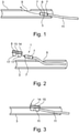
- a bike frame 3 which is designed as a tube, is shown schematically and a first method step for assembling and fixing the sensor housing 5 with cable 11 in the bike frame 3 is shown.
- the bike frame 3 shown in longitudinal section has a receptacle 9 as an opening in the upper tube wall, through which the sensor housing 5 is guided to the outside of the frame and as shown in FIG 2 shown, linked to a sensor mount 8 and can be fixed.
- the sensor housing 5 is made as an elongate sleeve, in particular in the form of a cylinder, and is made of a plastic material and has a ring-shaped detection area 6 in the central area, behind which the actual sensor for detecting magnetic pulses or signals is placed.
- Fixing areas 7 with a slightly smaller diameter are provided on both sides of the detection area 6 .
- the sensor housing 5 with the cable 11 is routed outwards through the mount 9 of the bike frame 3 in the direction of the arrow.
- the holding device 8 is slid onto the sensor housing 5 in the direction of the arrow or in a positive and non-positive manner, as in 6 shown clipped onto the fixing areas 7 .
- the sensor holder 8 which is preferably produced in one piece and from a plastic material, in particular thermoplastic material, has a plate-like head side 14, which is adjoined by a peripheral channel 15 at the bottom.
- the channel 15 is closed off at the bottom by a peripheral edge which, like the head side 14, has a slightly larger dimension, in particular in the form of an oval, and when inserted into the receptacle 9 seals it off.
- the sensor holder 8 has, as in 2 shown, two downwardly directed holding webs 17. These holding webs 17 are adapted to the outer contour of the sensor housing 5 and are in particular hook-like or L-shaped.
- the two holding webs 17 are preferably each provided on the opposite end region of the sensor holder on different outsides and with their hook opening opposite.
- the holding webs 17 can be designed such that the entire sensor holder 8 can be clipped onto the sensor housing 5 and a stable fixation between the sensor housing 5 and the sensor holder 8 is thus produced.
- a third assembly step the unit composed of sensor housing 5 and sensor holder 8 coupled in this way is returned to receptacle 9 .
- This can, as in 3 shown, be realized in such a way that first the channel 15 is brought into connection with the wall thickness of the opening 9 at an end region of the sensor holder and subsequently the entire sensor holder 8 is pressed, for example in a non-positive manner in accordance with the direction of the arrow, from the head side 14 into the opening 9 and securely closes it.
- the set 20 after 4 From the sensor housing 5 with a cable 11 and a sensor holder 28 , it has an elongated oval contour when viewed from the head side 29 .
- the sensor holder 28 also has two holding webs 17 directed downwards, which can be applied to the fixing regions 7 of the sensor housing 5 in a positive and/or non-positive manner.
- the set 20 of the bike sensor device 1 shown is intended specifically for bike frames 23 made from a solid material, in particular aluminum.
- a recess 24 is prepared in the bike frame 23 made of solid material, which is connected to a channel 25 introduced, for example, by drilling, through which the sensor housing 5 with the cable 11 can be pushed.
- the sensor housing 5 with the cable 11 can thus be guided through the channel 25 and the recess 24 in the direction of the arrow and pushed outwards.
- the sensor holder 28 is applied with its holding webs 17 to the sensor housing, for example clipped in the direction of the arrow. Subsequently, the set 20 of sensor housing 5 and sensor holder 28 inserted into the recess 24 is fastened, for example via a screw connection 35 through the head side 29 in the bike frame 23, so that the sensor present in the sensor housing 5 can be positioned precisely and the recess 24 is reached.
- the precise fixation of the sensor in the context of the set 20 on the bike frame 23 is, as in 8 shown schematically, so that the required by a magnet 50 at a rotation of the wheel 41 generated magnetic pulse or the magnetic field can be accurately detected.
- the simplified representation 8 shows the rear area of a bike frame 23 with a hub area 53 and a bike wheel 41 with spokes 42.
- a magnet 50 is attached to a spoke 42 and describes a running circle 51 when the bike wheel 41 rotates, which is shown in FIG Drive through detection area 6 ( 1 ) of the bike sensor device 1 is guided.
- the magnetic pulse or the magnetic field detected in the sensor when the bike wheel 41 rotates is sent via the sensor cable 11 to an evaluation unit such as a bike computer, so that the route of the bike wheel during one rotation but also at a large number of revolutions can be determined and other parameters such as speed and total distance and the like can also be calculated.
- the claimed bike sensor device 1 is therefore particularly suitable for retrofitting a corresponding bike, with self-assembly being relatively easy to implement.
- the speed driven can also be precisely calculated and saved.
Landscapes
- Engineering & Computer Science (AREA)
- Mechanical Engineering (AREA)
- Testing Or Calibration Of Command Recording Devices (AREA)
- Measuring Fluid Pressure (AREA)
- Motorcycle And Bicycle Frame (AREA)
Description
- Die Erfindung betrifft eine Bike-Sensor-Vorrichtung gemäß Oberbegriff des Anspruchs 1.
- Der hier verwendete Begriff "Bike" umfasst jegliche Art von Fahrrad wie City-Bike, Mountain-Bike, E-Bike und dergleichen. Im Hinblick auf die hier beanspruchte Bike-Sensor-Vorrichtung wird berücksichtigt, dass die derzeit angebotenen Bikes vom Nutzer aus ganz speziellen Baugruppen zusammengestellt werden können. Dies betrifft sowohl die Rahmen- und Materialstruktur, die für das entsprechende Bike eingesetzt werden sollen, oder spezielle Federungseinheiten für Frontgabeln, Sattelrohr oder dergleichen.
- Es ist daher bei neueren Bikes die Tendenz erkennbar, dass die Benutzer sich ihr entsprechendes Bike selbst zusammenstellen oder sogar zusammenbauen, wobei dies auch die elektronische Ausrüstung des Bikes betrifft.
- Hinzu kommt, dass bei E-Bikes eine Geschwindigkeitsbegrenzung vorgegeben ist, welche nicht überschritten werden soll, da bei höheren Geschwindigkeiten das entsprechende E-Bike in eine andere Klassifizierung fallen würde und damit zum Beispiel anmelde- und versicherungspflichtig werden würde.
- Die genaue Erfassung der mit einem Bike gefahrenen oder erreichbaren Geschwindigkeit, aber auch andere Daten wie zurückgelegte Gesamtstrecke oder Durchschnittsgeschwindigkeit, erlangen daher größere Bedeutung.
- Die bisherige Erfassung dieser Daten erfolgt meistens von einem Impulsgeber und Erfassungsbereich über außen am Bike-Rahmen geführte Kabel zu einer Auswerteeinheit, zum Beispiel einen Radcomputer oder Kilometerzähler.
- Diese Lösung passt jedoch nicht in ein optimales Bikedesign, so dass nach anderen Alternativen gesucht wird, die auch bei unterschiedlichen Rahmenstrukturen einsetzbar sind.
- Die Erfindung sieht daher vor, eine Bike-Sensor-Vorrichtung, die als Set zu verstehen ist, mit einem Sensorgehäuse und darin aufgenommenen Sensor mit angeschlossenem Sensorkabel so auszustatten, dass eine Sensorhalterung zur Aufnahme und Fixierung des Sensorgehäuses am oder im Biker-Rahmen vorgesehen wird, wobei die Sensorhalterung der entsprechenden Aufnahme beziehungsweise Öffnung am oder im Bike-Rahmen angepasst wird und die Sensorhalterung mit dem Sensorgehäuse formschlüssig und/oder kraftschlüssig am beziehungsweise im Bike-Rahmen aufgenommen ist.
- Die Rahmenstruktur des Bikes kann hierbei sowohl als Rohrrahmen oder als Vollmaterialrahmen ausgebildet sein.
- Aus der
DE 20 2015 007 540 U1 ist eine Anordnung zur Aufnahme eines Geschwindigkeitssensors im Rahmen eines Fahrrades bekannt. DieUS 2013/0228405 A1 betrifft einen Hallsensor, welcher im Bereich des Bremshebels eines E-Bikes vorgesehen ist, um Informationen zu ermitteln. Aus derDE 10 2016 000 498 A1 ist die Anordnung eines Pedalkraftsensors im Rahmen des Pedals bekannt. Eine ähnliche Vorrichtung ist auch aus derUS 2013/0322126 A1 bekannt. - Das erfindungsgemäße Konzept ermöglicht es, das entsprechende Sensorgehäuse mit angeschlossenem Kabel in einer im Bikerohr eingebrachten Aufnahme oder Öffnung zu verlegen oder zu führen und durch diese Öffnung das Gehäuse nach außen zu schieben, um dort an der Sensorhalterung, insbesondere einclipsbar fixiert zu werden. Sensorkabel mit Sensorgehäuse und aufgeclipster Sensorhalterung werden dann im Bikerohr zurückgezogen, bis die Kopfseite der Sensorhalterung die Öffnung der Aufnahme im Bikerohr bedeckt und abschließt.
- Bevorzugt weist die Kopfseite der Sensorhalterung im oberen Bereich eine umlaufende Rinne auf, deren Breite der Stärke des Bikerohres angepasst ist, so dass die Sensorhalterung die Aufnahme beziehungsweise Öffnung im Bikerohr formschlüssig abschließt.
- Das Sensorgehäuse kann zweckmäßigerweise eine längliche Hülsenstruktur aufweisen, die im mittleren Bereich einen ringförmigen Erfassungsbereich mit dahinter installiertem Sensor aufweist. Die Hülsenstruktur erlaubt es daher, die an der Sensorhalterung nach unten abstehenden Haltestege hakenförmig oder L-förmig auszulegen, so dass die Hülsenstruktur innerhalb der Haltestege fixiert wird.
- Die Haltestege werden dabei bevorzugt gegeneinander versetzt über die Länge der Sensorhalterung vorgesehen und ragen mit ihren Hakenbereichen gegeneinander, so dass eine gute Fixierung des Sensorgehäuses darin erreicht wird.
- An Stelle der Aufnahme und Öffnung in der Wandung des Rohrrahmens wird bei einer Ausbildung des Rahmens aus Vollmaterial eine Ausnehmung im Rahmen vorgesehen, und eine damit in Verbindung stehende relativ kurze Bohrung im Vollmaterial, so dass das Sensorgehäuse mit angeschlossenem Kabel durch die Bohrung in die Ausnehmung geschoben werden kann und dann in der aus dem Rahmen herausragenden Stellung die Sensorhalterung auf dem Sensorgehäuse aufgebracht oder aufgeclipst werden kann.
- Die entsprechende Sensorhalterung mit daran fixiertem Sensorgehäuse wird dann in die Ausnehmung des Rahmens zurückgeführt und kann dann beispielsweise über eine Schraubverbindung am Rahmen festgelegt werden und die entsprechende Ausnehmung, insbesondere abdichtend, abdecken.
- Vorzugsweise hat das Sensorgehäuse einen zentralen, insbesondere mittigen und ringförm igen Erfassungsbereich für den Sensor und beidseitig davon einen Fixierungsbereich, in dem die Sensorhalterung mit ihren Haltestegen das Sensorgehäuse fixieren kann.
- Der Erfassungsbereich des Sensors kann auch an der vorderen Stirn- und Abschlussfläche vorgesehen sein. Die ringförmige Verstärkung am Sensorgehäuse kann vorteilhafterweise zur genauen Positionsplatzierung und Halterung des Sensors ausgebildet sein. Ebenso ist es möglich, dass sich der Erfassungsbereich im Wesentlichen über die Länge des Sensorgehäuse erstreckt.
- Die Sensorhalterung, die zweckmäßigerweise insbesondere einstückig und aus einem duroplastischen oder thermoplastischen Kunststoffmaterial hergestellt ist, wird bevorzugt kopfseitig mit einer umlaufenden Rinne ausgebildet, wobei Letztere die Wandstärke der Aufnahme beziehungsweise Öffnung des Bikerohres aufnehmen kann, so dass damit ein formschlüssiger Abschluss gebildet wird und zum Beispiel keine Feuchtigkeit oder Wasser in das Innere des Bikerohres eindringen kann. Zum Inneren des Bike-Rahmens gerichtet ist die Sensorhalterung bevorzugt mit einem oder mehreren Haltestegen für die Fixierbereiche des Sensorgehäuses ausgebildet.
- Die Haltestege sind vorteilhafterweise haken- oder L-förmig ausgebildet und gegenläufig zueinander angeordnet. In diesem Sinn sind an den Endbereichen der Sensorhalterung über deren Länge jeweils ein Haltesteg vorgesehen, der im unteren Bereich bogenartig geformt ist, wobei die bogenartigen oder hakenförmigen Bereiche gegeneinander gerichtet sind.
- Nach dem Einsetzen des Sensorgehäuses in diese Hakenbereiche wird daher das Sensorgehäuse form- und kraftschlüssig festgelegt. Auch die Kopfseite der Sensorhalterung ist so ausgebildet, dass sie formschlüssig und insbesondere abdichtend die Ausnehmung beziehungsweise Öffnung im oder am Bike-Rahmen abdeckt und abschließt.
- Die Kopfseite der Sensorhalterung ist insbesondere als längliches Oval ausgebildet und der Aufnahme beziehungsweise Öffnung im Bike-Rahmen angepasst, so dass ein Abschluss der Öffnung oder Ausnehmung erzeugt wird und in diesem Bereich keine Feuchtigkeit in den Bike-Rahmen eintreten kann.
- Insbesondere bei einem Bike-Rahmen aus Vollmaterial wird die Kopfseite der Sensorhalterung plattenartig ausgebildet und mit einem Befestigungsbereich versehen. Auf diese Weise kann mittels einer Schraubbefestigung durch die Kopfseite gegen den Bike-Rahmen die zusammengeclipste Einheit von Sensorgehäuse und Sensorhalterung am Bike-Rahmen befestigt werden.
- Die Sensorhalterung kann in einer einfachen Form als Klemmhalter ausgebildet sein. Hierbei wird ein bogenförmiger Bereich zur formschlüssigen Aufnahme der Rundkontur, insbesondere der mittigen ringförmigen Verstärkung des Sensors, vorgesehen. Auch ist ein Befestigungsschenkel zur Fixierung am Bikerahmen vorhanden.
- Zusätzlich kann eine Drehsicherung beabstandet von der Fixierung, insbesondere in Form eines zum Beispiel zylindrischen Bolzens berücksichtigt werden, der eine Drehblockierung am Bikerahmen für Sensor und Sensorhalterung bewirkt.
- Verfahrensmäßig kann daher bei dieser Bike-Sensor-Vorrichtung das Sensorgehäuse mit angeschlossenem Sensorkabel zum Beispiel durch die Rohröffnung des Bike-Rahmens geführt und durch die Ausnehmung beziehungsweise Öffnung in einem Wandabschnitt des Sensorrohres nach außen geführt und an dieser Stelle mit der Sensorhalterung verbunden beziehungsweise eingeclipst werden.
- Es wird nachfolgend das Sensorgehäuse mit darauf fixierter Sensorhalterung in die Ausnehmung beziehungsweise Öffnung zurückgeführt und dort einrastend in die Wandung des Bikerohres oder zum Beispiel mittels einer Schraubbefestigung am Bikerohr festgelegt.
- Die Erfindung wird nachfolgend anhand schematischer Beispiele noch näher erläutert. Es zeigen:
- Fig. 1
- einen schematischen Längsschnitt durch den Bereich eines Bikerahmens, der als Rohr ausgebildet ist, in dem ein Sensorgehäuse mit Kabel eingeführt ist und in Pfeilrichtung durch eine Öffnung nach außen geführt werden kann;
- Fig. 2
- die Darstellung nach
Fig. 1 , wobei das Sensorgehäuse nach außen geführt ist und eine Sensorhalterung in Pfeilrichtung auf dem Sensorgehäuse aufgebracht oder aufgeclipst werden kann; - Fig. 3
- einen nachfolgenden Schritt zu der Darstellung nach
Fig. 2 , wobei die auf dem Sensorgehäuse aufgebrachte Sensorhalterung in die Öffnung des Bike-Rahmens eingesetzt wird und in Pfeilrichtung so eingedrückt werden kann, dass die Wandung des Rohres in einer kopfseitigen Rinne der Sensorhalterung zu liegen kommt; - Fig. 4
- die Baugruppen der Bike-Sensor-Vorrichtung mit Sensorgehäuse und Sensorkabel mit darüber angeordneter Sensorhalterung und eine kopfseitige Ansicht der Sensorhalterung von oben mit einer Befestigungsschraube;
- Fig. 5
- der Einführvorgang des Sensorgehäuses mit Kabel in ein Bikerohr aus Vollmaterial mit darin vorgesehener Aufnahme und einen Verlegekanal;
- Fig. 6
- die Darstellung nach
Fig. 5 in der Phase, in der das Sensorgehäuse nach außen geführt ist und kurz vor der Zusammenführung und Befestigung mit der Sensorhalterung gezeigt ist; - Fig. 7
- die Endphase des Zusammenbaus des Sets der Bike-Sensor-Vorrichtung, wobei die Sensorhalterung mit Sensorgehäuse in der Ausnehmung platziert ist und kopfseitig mit einer Schraubverbindung im Bike-Rahmen festgelegt wird; und
- Fig. 8
- eine vereinfachte bruchstückartige Darstellung eines hinteren Rahmenbereichs eines Bikes mit Reifen und Speichen sowie angebrachtem Magneten zur Impulserzeugung beim Vorbeiführen an einer am Bike-Rahmen befestigten Sensorhalterung auf dem Rotationskreis, der mit unterbrochenen Strichen dargestellt ist.
- In
Fig. 1 ist schematisch ein Bike-Rahmen 3, der als Rohr ausgebildet ist, dargestellt und ein erster Verfahrensschritt zur Montage und Festlegung des Sensorgehäuses 5 mit Kabel 11 im Bike-Rahmen 3 gezeigt. - Der im Längsschnitt dargestellte Bike-Rahmen 3 weist im Beispiel in der oberen Rohrwandung eine Aufnahme 9 als Öffnung auf, durch die das Sensorgehäuse 5 nach außerhalb des Rahmens geführt ist und wie in
Fig. 2 gezeigt, mit einer Sensorhalterung 8 verknüpft und festgelegt werden kann. - Das Sensorgehäuse 5 ist als längliche Hülse, insbesondere in Art eines Zylinders und aus einem Kunststoffmaterial hergestellt und weist im mittleren Bereich einen ringförmigen Erfassungsbereich 6 auf, hinter dem der eigentliche Sensor zur Erfassung magnetischer Impulse oder Signale platziert ist.
- Beidseitig vom Erfassungsbereich 6 sind etwas durchmesserkleinere Fixierbereiche 7 vorgesehen.
- Das Sensorgehäuse 5 mit Kabel 11 wird in Pfeilrichtung durch die Aufnahme 9 des Bike-Rahmens 3 nach außen geführt. Dort wird, wie in
Fig. 2 gezeigt, die Halteeinrichtung 8 in Pfeilrichtung auf das Sensorgehäuse 5 aufgeschoben oder form- und kraftschlüssig, wie inFig. 6 gezeigt, auf die Fixierbereiche 7 aufgeclipst. - Die bevorzugt einstückig und aus einem Kunststoffmaterial, insbesondere thermoplastischen Kunststoff, hergestellte Sensorhalterung 8 weist eine plattenartige Kopfseite 14 auf, an die sich nach unten eine umlaufende Rinne 15 anschließt. Die Rinne 15 wird nach unten durch einen umlaufenden Rand abgeschlossen, der ebenso wie die Kopfseite 14 eine geringfügig größere Abmessung, insbesondere in Art eines Ovals, aufweist und im eingesetzten Zustand in die Aufnahme 9 diese abdichtend abschließt.
- Die Sensorhalterung 8 hat, wie in
Fig. 2 gezeigt, zwei nach unten gerichtete Haltestege 17. Diese Haltestege 17 sind der Außenkontur des Sensorgehäuses 5 angepasst und insbesondere hakenartig oder L-förmig ausgebildet. - Die zwei Haltestege 17 sind bevorzugt jeweils am entgegengesetzten Endbereich der Sensorhalterung auf unterschiedlichen Außenseiten und mit ihrer Hakenöffnung entgegengesetzt vorgesehen.
- Mit dieser Ausgestaltung ist es möglich, die Sensorhalterung 8 entweder wie in
Fig. 2 gezeigt in Längsrichtung des Sensorgehäuses aufzuschieben, so dass der Erfassungsbereich 6 im Zwischenspalt zwischen den beiden Haltestegen 17 zu liegen kommt. - Die Haltestege 17 können aber trotz ihrer Hakenausbildung im unteren Bereich derart beschaffen sein, dass die gesamte Sensorhalterung 8 auf das Sensorgehäuse 5 aufgeclipst werden kann und eine stabile Fixierung zwischen dem Sensorgehäuse 5 und der Sensorhalterung 8 damit erzeugt wird.
- In einem dritten Montageschritt wird die derart gekoppelte Einheit aus Sensorgehäuse 5 und Sensorhalterung 8 in die Aufnahme 9 zurückgeführt. Dies kann, wie in
Fig. 3 gezeigt, in der Art realisiert werden, dass zunächst die Rinne 15 an einem Endbereich der Sensorhalterung mit der Wandstärke der Öffnung 9 in Verbindung gebracht wird und nachfolgend die gesamte Sensorhalterung 8 beispielsweise kraftschlüssig entsprechend der Pfeilrichtung von der Kopfseite 14 in die Öffnung 9 eingedrückt wird und diese sicher abschließt. - Auf diese Weise ist eine stabile und sichere Fixierung des Sensorgehäuses im Bike-Rahmen 3 gewährleistet und eine Abdichtung zum Inneren des Bike-Rahmens 3 oder einer Ausnehmung 24 (
Figuren 6, 7 ) erreicht. - In
Fig. 4 ist schematisch eine etwas abgewandelte Alternative zur Bike-Sensor-Vorrichtung 1 nach denFiguren 1 bis 3 dargestellt. Das Set 20 nachFig. 4 aus Sensorgehäuse 5 mit Kabel 11 und einer Sensorhalterung 28 weist auf die Kopfseite 29 gesehen, eine längliche Ovalkontur auf. Nach unten gerichtet hat die Sensorhalterung 28 ebenfalls zwei Haltestege 17, die form- und/oder kraftschlüssig auf die Fixierbereiche 7 des Sensorgehäuses 5 aufgebracht werden können. - Das in
Fig. 4 gezeigte Set 20 der Bike-Sensor-Vorrichtung 1 ist speziell für Bike-Rahmen 23 aus einem Vollmaterial, insbesondere Aluminium, vorgesehen. Im Bike-Rahmen 23 aus Vollmaterial wird hierzu eine Ausnehmung 24 vorbereitet, die mit einem zum Beispiel bohrtechnisch eingebrachten Kanal 25, durch den das Sensorgehäuse 5 mit Kabel 11 geschoben werden kann, in Verbindung steht. - Entsprechend
Fig. 5 kann somit das Sensorgehäuse 5 mit Kabel 11 durch den Kanal 25 und die Ausnehmung 24 in Pfeilrichtung geführt und nach außen geschoben werden. - Der weitere Montageschritt zur Befestigung des Sets 20 im Bike-Rahmen 23 ist in Figuren 6 und 7 dargestellt.
- Gemäß
Fig. 6 wird die Sensorhalterung 28 mit ihren Haltestegen 17 auf das Sensorgehäuse aufgebracht, zum Beispiel in Pfeilrichtung aufgeclipst. Nachfolgend wird dann das in die Ausnehmung 24 eingesetzte Set 20 aus Sensorgehäuse 5 und Sensorhalterung 28 beispielsweise über eine Schraubverbindung 35 durch die Kopfseite 29 im Bike-Rahmen 23 befestigt, so dass eine genaue Platzierung des im Sensorgehäuse 5 vorhandenen Sensors und eine Abdichtung der Ausnehmung 24 erreicht wird. - Die präzise Fixierung des Sensors im Rahmen des Sets 20 am Bike-Rahmen 23 ist, wie in
Fig. 8 schematisch gezeigt, erforderlich, damit der durch einen Magneten 50 bei einer Drehung des Rades 41 erzeugte magnetische Puls beziehungsweise des magnetischen Feldes genau erfasst werden kann. - Die vereinfachte Darstellung nach
Fig. 8 zeigt den hinteren Bereich eines Bike-Rahmens 23 mit Nabenbereich 53 und einem mit Speichen 42 aufweisenden Bike-Rad 41. Ein Magnet 50 ist im Beispiel an einer Speiche 42 befestigt und beschreibt bei einer Rotation des Bike-Rades 41 einen Laufkreis 51, der in Fahrt durch den Erfassungsbereich 6 (Fig. 1 ) der Bike-Sensor-Vorrichtung 1 geführt ist. - Der bei einer Drehung des Bike-Rades 41 im Sensor erfasste magnetische Impuls beziehungsweise das magnetische Feld, wird signalmäßig über das Sensorkabel 11 zu einer Auswerteeinheit wie einem Bike-Computer geführt, so dass darüber die Strecke des Bike-Rades bei einer Umdrehung aber auch bei einer Vielzahl von Umdrehungen ermittelt und auch weitere Parameter wie Geschwindigkeit und Gesamtstrecke und dergleichen, berechnet werden kann.
- Die beanspruchte Bike-Sensor-Vorrichtung 1 eignet sich daher insbesondere für eine Nachrüstung eines entsprechenden Bikes, wobei eine Selbstmontage in relativ einfacher Weise zu realisieren ist.
- In Kombination mit einer Auswerteeinheit wie einem Bike-Computer kann dabei auch die gefahrene Geschwindigkeit genau berechnet und abgespeichert werden.
Claims (9)
- Bike-Sensor-Vorrichtung (1) miteinem Sensorgehäuse (5) und damit verbundenem Sensorkabel (11),einer Sensorhalterung (8) zur Fixierung des Sensorgehäuses (5) am oder im Bike-Rahmen (3, 23)),wobei die Sensorhalterung (8) einer Aufnahme (9) oder Öffnung am/im Bike-Rahmen (3, 23) angepasst ist, undwobei die Sensorhalterung (8) mit dem Sensorgehäuse (5) form- und/oder kraftschlüssig am/im Bike-Rahmen (3, 23) aufgenommen istdadurch gekennzeichnet,dass die Sensorhalterung (8) kopfseitig (14) in die Aufnahme (9) oder Öffnung des Bike-Rahmens (3, 23) einsetzbar ist, und zum Inneren des Bike-Rahmens (3, 23) gerichtet mindestens einen oder mehrere Haltestege (17) für Fixierungsbereiche (7) des Sensorgehäuses (5) aufweist.
- Bike-Sensor-Vorrichtung nach Anspruch 1,
dadurch gekennzeichnet,
dass das Sensorgehäuse (5) einen zentralen, insbesondere ringförmigen Erfassungsbereich (6) und beidseitig davon einen Fixierungsbereich (7) für die Sensorhalterung (8) aufweist. - Bike-Sensor-Vorrichtung nach Anspruch 1 oder 2,
dadurch gekennzeichnet,
dass die Sensorhalterung (8) kopfseitig (14) mit umlaufender Rinne (15) in die Aufnahme (9) oder Öffnung des Bike-Rahmens (3, 23) einsetzbar ist. - Bike-Sensor-Vorrichtung nach einem der Ansprüche 1 bis 3,
dadurch gekennzeichnet,
dass die Sensorhalterung (8) einstückig aus Kunststoff, insbesondere einem duroplastischen oder thermoplastischen Kunststoff, ausgebildet ist. - Bike-Sensor-Vorrichtung nach einem der Ansprüche 1 bis 4,
dadurch gekennzeichnet,
dass die Haltestege (17) haken- oder L-förmig ausgebildet und gegenläufig zur Fixierung des Sensorgehäuses (5) an der Sensorhalterung (8) angeordnet sind. - Bike-Sensor-Vorrichtung nach einem der Ansprüche 1 bis 5,
dadurch gekennzeichnet,
dass die Kopfseite (14) der Sensorhalterung (8) formschlüssig und insbesondere abdichtend in einer Ausnehmung (9) oder Öffnung im/am Bike-Rahmen (3, 23) aufnehmbar ist. - Bike-Sensor-Vorrichtung nach einem der Ansprüche 1 bis 6,
dadurch gekennzeichnet,
dass die Kopfseite (14, 29) der Sensorhalterung (8, 28) als Aufnahme (24) oder Öffnung (9) überdeckendes, insbesondere längliches Oval ausgebildet ist. - Bike-Sensor-Vorrichtung nach einem der Ansprüche 1 bis 7,
dadurch gekennzeichnet,
dass die Kopfseite (28) plattenartig und mit einem Befestigungsbereich (34) am Bike-Rahmen (23) ausgebildet ist. - Bike-Sensor-Vorrichtung nach einem der Ansprüche 1 bis 8,
dadurch gekennzeichnet,
dass die Sensorhalterung (8) zum Einsetzen in einen als Rohrrahmen oder als Vollmaterial-Rahmen (23) ausgebildeten Bike-Rahmen (3, 23) ausgebildet ist.
Applications Claiming Priority (2)
| Application Number | Priority Date | Filing Date | Title |
|---|---|---|---|
| DE202018106420.7U DE202018106420U1 (de) | 2018-11-13 | 2018-11-13 | Bike-Sensor-Vorrichtung |
| PCT/EP2019/080852 WO2020099310A1 (de) | 2018-11-13 | 2019-11-11 | Bike-sensor-vorrichtung |
Publications (2)
| Publication Number | Publication Date |
|---|---|
| EP3774510A1 EP3774510A1 (de) | 2021-02-17 |
| EP3774510B1 true EP3774510B1 (de) | 2022-03-09 |
Family
ID=64951707
Family Applications (1)
| Application Number | Title | Priority Date | Filing Date |
|---|---|---|---|
| EP19805562.6A Active EP3774510B1 (de) | 2018-11-13 | 2019-11-11 | Bike-sensor-vorrichtung |
Country Status (4)
| Country | Link |
|---|---|
| EP (1) | EP3774510B1 (de) |
| DE (1) | DE202018106420U1 (de) |
| ES (1) | ES2911525T3 (de) |
| WO (1) | WO2020099310A1 (de) |
Families Citing this family (1)
| Publication number | Priority date | Publication date | Assignee | Title |
|---|---|---|---|---|
| DE102021112926A1 (de) * | 2021-05-19 | 2022-11-24 | Bayerische Motoren Werke Aktiengesellschaft | Halterung für eine Kamera und einen GPS-Sensor |
Family Cites Families (6)
| Publication number | Priority date | Publication date | Assignee | Title |
|---|---|---|---|---|
| US7878521B2 (en) * | 2007-04-16 | 2011-02-01 | Trek Bicycle Corporation | Bicycle frame with device cavity |
| DE202011103320U1 (de) * | 2011-07-12 | 2012-11-21 | Pending System Gmbh & Co. Kg | Zugverlegung für ein Zweirad, insbesondere für ein Mountainbike oder Rennrad, sowie Rahmen und Schaltauge für die Verwendung einer Zugverlegung |
| US20130228405A1 (en) * | 2012-03-01 | 2013-09-05 | Szu-Fang Tsai | Brake operating device of electric bicycle with hall-effect sensor |
| US8800389B2 (en) * | 2012-03-07 | 2014-08-12 | Shimano, Inc. | Bicycle crank arm with an input force processing apparatus |
| US9581508B2 (en) * | 2015-01-23 | 2017-02-28 | Shimano Inc. | Bicycle pedaling force detector |
| DE202015007540U1 (de) * | 2015-10-31 | 2015-12-14 | Derby Cycle Werke Gmbh | Anordnung zur Aufnahme einer Geschwindigkeitsmesseinrichtung an einem Fahrrad |
-
2018
- 2018-11-13 DE DE202018106420.7U patent/DE202018106420U1/de active Active
-
2019
- 2019-11-11 EP EP19805562.6A patent/EP3774510B1/de active Active
- 2019-11-11 ES ES19805562T patent/ES2911525T3/es active Active
- 2019-11-11 WO PCT/EP2019/080852 patent/WO2020099310A1/de not_active Ceased
Also Published As
| Publication number | Publication date |
|---|---|
| ES2911525T3 (es) | 2022-05-19 |
| EP3774510A1 (de) | 2021-02-17 |
| WO2020099310A1 (de) | 2020-05-22 |
| DE202018106420U1 (de) | 2018-12-19 |
Similar Documents
| Publication | Publication Date | Title |
|---|---|---|
| EP2158120B1 (de) | Schaltauge mit einsetzhilfe | |
| DE4243623C2 (de) | Drehzahlerfassungsvorrichtung | |
| EP3774510B1 (de) | Bike-sensor-vorrichtung | |
| EP3556647A1 (de) | Vorrichtung zur befestigung eines schaltwerks an einem fahrradrahmen | |
| EP0728659B1 (de) | Fahrradschloss des Ringbügeltyps | |
| DE202022107086U1 (de) | Lenkeranordnung | |
| EP3162689A1 (de) | Anordnung zur aufnahme einer geschwindigkeitsmesseinrichtung an einem fahrrad | |
| DE102019125405A1 (de) | Sensor und System aus dem Sensor und einer Befestigungseinrichtung | |
| EP2881314B1 (de) | Fahrradgriff | |
| DE602005005581T2 (de) | Abdeckungsvorrichtung einer elektrischen Verdrahtung für Fahrräder | |
| DE60019479T2 (de) | Magnethalter für eine Speiche | |
| EP4330121B1 (de) | Antriebsvorrichtung für ein elektrofahrrad und elektrofahrrad | |
| DE3421210A1 (de) | Fahrradkettenkasten aus kunststoff | |
| DE10042821C2 (de) | Anschließvorrichtung für Fahrräder | |
| DE19707067C1 (de) | Lenksäuleneinheit für einen Kraftwagen | |
| DE102017201995A1 (de) | Fahrradrahmen-Steuerrohr | |
| DE102023130751B3 (de) | Radschützer für ein Fahrrad | |
| DE102004021382B4 (de) | Befestigungselement für einen Sensorkopf | |
| DE102016203218B4 (de) | Fahrzeugbauteil mit einem Montagebauteil zur Anbringung einer Komponente | |
| DE10028544A1 (de) | Umrüstbare Kabel-Endanschläge/-durchführungen | |
| EP4488152A2 (de) | Fahrrad mit einem radschützer sowie radschützer | |
| EP2873597B1 (de) | Vorrichtung zur Befestigung einer Umlaufstrebe am Rahmen eines Zweirades sowie Anordnung der Umlaufstrebe an dem Rahmen des Zweirades | |
| DE102018008566A1 (de) | Rastverbindungsanordnung zwischen einer Rasthülse und einem Rastbolzen und Anordnung zum Befestigen eines Bauteils an einer Fahrzeugkarosserie | |
| DE3916367A1 (de) | Bremsdrehlager | |
| EP3048034A1 (de) | Radschützer für ein fahrrad mit einfedernder vorderradgabel |
Legal Events
| Date | Code | Title | Description |
|---|---|---|---|
| STAA | Information on the status of an ep patent application or granted ep patent |
Free format text: STATUS: UNKNOWN |
|
| STAA | Information on the status of an ep patent application or granted ep patent |
Free format text: STATUS: THE INTERNATIONAL PUBLICATION HAS BEEN MADE |
|
| PUAI | Public reference made under article 153(3) epc to a published international application that has entered the european phase |
Free format text: ORIGINAL CODE: 0009012 |
|
| STAA | Information on the status of an ep patent application or granted ep patent |
Free format text: STATUS: REQUEST FOR EXAMINATION WAS MADE |
|
| 17P | Request for examination filed |
Effective date: 20201111 |
|
| AK | Designated contracting states |
Kind code of ref document: A1 Designated state(s): AL AT BE BG CH CY CZ DE DK EE ES FI FR GB GR HR HU IE IS IT LI LT LU LV MC MK MT NL NO PL PT RO RS SE SI SK SM TR |
|
| AX | Request for extension of the european patent |
Extension state: BA ME |
|
| GRAP | Despatch of communication of intention to grant a patent |
Free format text: ORIGINAL CODE: EPIDOSNIGR1 |
|
| STAA | Information on the status of an ep patent application or granted ep patent |
Free format text: STATUS: GRANT OF PATENT IS INTENDED |
|
| GRAJ | Information related to disapproval of communication of intention to grant by the applicant or resumption of examination proceedings by the epo deleted |
Free format text: ORIGINAL CODE: EPIDOSDIGR1 |
|
| STAA | Information on the status of an ep patent application or granted ep patent |
Free format text: STATUS: REQUEST FOR EXAMINATION WAS MADE |
|
| GRAP | Despatch of communication of intention to grant a patent |
Free format text: ORIGINAL CODE: EPIDOSNIGR1 |
|
| STAA | Information on the status of an ep patent application or granted ep patent |
Free format text: STATUS: GRANT OF PATENT IS INTENDED |
|
| INTG | Intention to grant announced |
Effective date: 20211020 |
|
| INTG | Intention to grant announced |
Effective date: 20211112 |
|
| GRAS | Grant fee paid |
Free format text: ORIGINAL CODE: EPIDOSNIGR3 |
|
| GRAA | (expected) grant |
Free format text: ORIGINAL CODE: 0009210 |
|
| STAA | Information on the status of an ep patent application or granted ep patent |
Free format text: STATUS: THE PATENT HAS BEEN GRANTED |
|
| DAV | Request for validation of the european patent (deleted) | ||
| DAX | Request for extension of the european patent (deleted) | ||
| AK | Designated contracting states |
Kind code of ref document: B1 Designated state(s): AL AT BE BG CH CY CZ DE DK EE ES FI FR GB GR HR HU IE IS IT LI LT LU LV MC MK MT NL NO PL PT RO RS SE SI SK SM TR |
|
| REG | Reference to a national code |
Ref country code: CH Ref legal event code: EP Ref country code: AT Ref legal event code: REF Ref document number: 1473940 Country of ref document: AT Kind code of ref document: T Effective date: 20220315 |
|
| REG | Reference to a national code |
Ref country code: DE Ref legal event code: R096 Ref document number: 502019003691 Country of ref document: DE |
|
| REG | Reference to a national code |
Ref country code: IE Ref legal event code: FG4D Free format text: LANGUAGE OF EP DOCUMENT: GERMAN |
|
| REG | Reference to a national code |
Ref country code: NL Ref legal event code: FP |
|
| REG | Reference to a national code |
Ref country code: RO Ref legal event code: EPE Ref country code: ES Ref legal event code: FG2A Ref document number: 2911525 Country of ref document: ES Kind code of ref document: T3 Effective date: 20220519 |
|
| REG | Reference to a national code |
Ref country code: LT Ref legal event code: MG9D |
|
| PG25 | Lapsed in a contracting state [announced via postgrant information from national office to epo] |
Ref country code: SE Free format text: LAPSE BECAUSE OF FAILURE TO SUBMIT A TRANSLATION OF THE DESCRIPTION OR TO PAY THE FEE WITHIN THE PRESCRIBED TIME-LIMIT Effective date: 20220309 Ref country code: RS Free format text: LAPSE BECAUSE OF FAILURE TO SUBMIT A TRANSLATION OF THE DESCRIPTION OR TO PAY THE FEE WITHIN THE PRESCRIBED TIME-LIMIT Effective date: 20220309 Ref country code: NO Free format text: LAPSE BECAUSE OF FAILURE TO SUBMIT A TRANSLATION OF THE DESCRIPTION OR TO PAY THE FEE WITHIN THE PRESCRIBED TIME-LIMIT Effective date: 20220609 Ref country code: LT Free format text: LAPSE BECAUSE OF FAILURE TO SUBMIT A TRANSLATION OF THE DESCRIPTION OR TO PAY THE FEE WITHIN THE PRESCRIBED TIME-LIMIT Effective date: 20220309 Ref country code: HR Free format text: LAPSE BECAUSE OF FAILURE TO SUBMIT A TRANSLATION OF THE DESCRIPTION OR TO PAY THE FEE WITHIN THE PRESCRIBED TIME-LIMIT Effective date: 20220309 Ref country code: BG Free format text: LAPSE BECAUSE OF FAILURE TO SUBMIT A TRANSLATION OF THE DESCRIPTION OR TO PAY THE FEE WITHIN THE PRESCRIBED TIME-LIMIT Effective date: 20220609 |
|
| PG25 | Lapsed in a contracting state [announced via postgrant information from national office to epo] |
Ref country code: LV Free format text: LAPSE BECAUSE OF FAILURE TO SUBMIT A TRANSLATION OF THE DESCRIPTION OR TO PAY THE FEE WITHIN THE PRESCRIBED TIME-LIMIT Effective date: 20220309 Ref country code: GR Free format text: LAPSE BECAUSE OF FAILURE TO SUBMIT A TRANSLATION OF THE DESCRIPTION OR TO PAY THE FEE WITHIN THE PRESCRIBED TIME-LIMIT Effective date: 20220610 Ref country code: FI Free format text: LAPSE BECAUSE OF FAILURE TO SUBMIT A TRANSLATION OF THE DESCRIPTION OR TO PAY THE FEE WITHIN THE PRESCRIBED TIME-LIMIT Effective date: 20220309 |
|
| PG25 | Lapsed in a contracting state [announced via postgrant information from national office to epo] |
Ref country code: SM Free format text: LAPSE BECAUSE OF FAILURE TO SUBMIT A TRANSLATION OF THE DESCRIPTION OR TO PAY THE FEE WITHIN THE PRESCRIBED TIME-LIMIT Effective date: 20220309 Ref country code: SK Free format text: LAPSE BECAUSE OF FAILURE TO SUBMIT A TRANSLATION OF THE DESCRIPTION OR TO PAY THE FEE WITHIN THE PRESCRIBED TIME-LIMIT Effective date: 20220309 Ref country code: PT Free format text: LAPSE BECAUSE OF FAILURE TO SUBMIT A TRANSLATION OF THE DESCRIPTION OR TO PAY THE FEE WITHIN THE PRESCRIBED TIME-LIMIT Effective date: 20220711 Ref country code: EE Free format text: LAPSE BECAUSE OF FAILURE TO SUBMIT A TRANSLATION OF THE DESCRIPTION OR TO PAY THE FEE WITHIN THE PRESCRIBED TIME-LIMIT Effective date: 20220309 |
|
| PG25 | Lapsed in a contracting state [announced via postgrant information from national office to epo] |
Ref country code: PL Free format text: LAPSE BECAUSE OF FAILURE TO SUBMIT A TRANSLATION OF THE DESCRIPTION OR TO PAY THE FEE WITHIN THE PRESCRIBED TIME-LIMIT Effective date: 20220309 Ref country code: IS Free format text: LAPSE BECAUSE OF FAILURE TO SUBMIT A TRANSLATION OF THE DESCRIPTION OR TO PAY THE FEE WITHIN THE PRESCRIBED TIME-LIMIT Effective date: 20220709 Ref country code: AL Free format text: LAPSE BECAUSE OF FAILURE TO SUBMIT A TRANSLATION OF THE DESCRIPTION OR TO PAY THE FEE WITHIN THE PRESCRIBED TIME-LIMIT Effective date: 20220309 |
|
| REG | Reference to a national code |
Ref country code: DE Ref legal event code: R097 Ref document number: 502019003691 Country of ref document: DE |
|
| PLBE | No opposition filed within time limit |
Free format text: ORIGINAL CODE: 0009261 |
|
| STAA | Information on the status of an ep patent application or granted ep patent |
Free format text: STATUS: NO OPPOSITION FILED WITHIN TIME LIMIT |
|
| PG25 | Lapsed in a contracting state [announced via postgrant information from national office to epo] |
Ref country code: DK Free format text: LAPSE BECAUSE OF FAILURE TO SUBMIT A TRANSLATION OF THE DESCRIPTION OR TO PAY THE FEE WITHIN THE PRESCRIBED TIME-LIMIT Effective date: 20220309 |
|
| 26N | No opposition filed |
Effective date: 20221212 |
|
| PG25 | Lapsed in a contracting state [announced via postgrant information from national office to epo] |
Ref country code: SI Free format text: LAPSE BECAUSE OF FAILURE TO SUBMIT A TRANSLATION OF THE DESCRIPTION OR TO PAY THE FEE WITHIN THE PRESCRIBED TIME-LIMIT Effective date: 20220309 |
|
| P01 | Opt-out of the competence of the unified patent court (upc) registered |
Effective date: 20230511 |
|
| PG25 | Lapsed in a contracting state [announced via postgrant information from national office to epo] |
Ref country code: MC Free format text: LAPSE BECAUSE OF FAILURE TO SUBMIT A TRANSLATION OF THE DESCRIPTION OR TO PAY THE FEE WITHIN THE PRESCRIBED TIME-LIMIT Effective date: 20220309 |
|
| REG | Reference to a national code |
Ref country code: BE Ref legal event code: MM Effective date: 20221130 |
|
| REG | Reference to a national code |
Ref country code: DE Ref legal event code: R081 Ref document number: 502019003691 Country of ref document: DE Owner name: K.W.H. CICLOSPORT VERTRIEBS GMBH, DE Free format text: FORMER OWNER: K.W.H. CICLOSPORT VERTRIEBS GMBH, 82166 GRAEFELFING, DE |
|
| PG25 | Lapsed in a contracting state [announced via postgrant information from national office to epo] |
Ref country code: LU Free format text: LAPSE BECAUSE OF NON-PAYMENT OF DUE FEES Effective date: 20221111 |
|
| PG25 | Lapsed in a contracting state [announced via postgrant information from national office to epo] |
Ref country code: IE Free format text: LAPSE BECAUSE OF NON-PAYMENT OF DUE FEES Effective date: 20221111 |
|
| PG25 | Lapsed in a contracting state [announced via postgrant information from national office to epo] |
Ref country code: BE Free format text: LAPSE BECAUSE OF NON-PAYMENT OF DUE FEES Effective date: 20221130 |
|
| PGFP | Annual fee paid to national office [announced via postgrant information from national office to epo] |
Ref country code: RO Payment date: 20231206 Year of fee payment: 5 Ref country code: CZ Payment date: 20231129 Year of fee payment: 5 |
|
| PG25 | Lapsed in a contracting state [announced via postgrant information from national office to epo] |
Ref country code: CY Free format text: LAPSE BECAUSE OF FAILURE TO SUBMIT A TRANSLATION OF THE DESCRIPTION OR TO PAY THE FEE WITHIN THE PRESCRIBED TIME-LIMIT Effective date: 20220309 |
|
| PG25 | Lapsed in a contracting state [announced via postgrant information from national office to epo] |
Ref country code: MK Free format text: LAPSE BECAUSE OF FAILURE TO SUBMIT A TRANSLATION OF THE DESCRIPTION OR TO PAY THE FEE WITHIN THE PRESCRIBED TIME-LIMIT Effective date: 20220309 Ref country code: HU Free format text: LAPSE BECAUSE OF FAILURE TO SUBMIT A TRANSLATION OF THE DESCRIPTION OR TO PAY THE FEE WITHIN THE PRESCRIBED TIME-LIMIT; INVALID AB INITIO Effective date: 20191111 |
|
| PG25 | Lapsed in a contracting state [announced via postgrant information from national office to epo] |
Ref country code: MT Free format text: LAPSE BECAUSE OF FAILURE TO SUBMIT A TRANSLATION OF THE DESCRIPTION OR TO PAY THE FEE WITHIN THE PRESCRIBED TIME-LIMIT Effective date: 20220309 |
|
| PGFP | Annual fee paid to national office [announced via postgrant information from national office to epo] |
Ref country code: NL Payment date: 20241120 Year of fee payment: 6 |
|
| PGFP | Annual fee paid to national office [announced via postgrant information from national office to epo] |
Ref country code: DE Payment date: 20241127 Year of fee payment: 6 |
|
| PGFP | Annual fee paid to national office [announced via postgrant information from national office to epo] |
Ref country code: GB Payment date: 20241121 Year of fee payment: 6 |
|
| PGFP | Annual fee paid to national office [announced via postgrant information from national office to epo] |
Ref country code: FR Payment date: 20241121 Year of fee payment: 6 |
|
| PGFP | Annual fee paid to national office [announced via postgrant information from national office to epo] |
Ref country code: AT Payment date: 20241118 Year of fee payment: 6 |
|
| PGFP | Annual fee paid to national office [announced via postgrant information from national office to epo] |
Ref country code: IT Payment date: 20241129 Year of fee payment: 6 Ref country code: ES Payment date: 20241213 Year of fee payment: 6 |
|
| PGFP | Annual fee paid to national office [announced via postgrant information from national office to epo] |
Ref country code: CH Payment date: 20241201 Year of fee payment: 6 |
|
| PG25 | Lapsed in a contracting state [announced via postgrant information from national office to epo] |
Ref country code: RO Free format text: LAPSE BECAUSE OF NON-PAYMENT OF DUE FEES Effective date: 20241111 |
|
| PG25 | Lapsed in a contracting state [announced via postgrant information from national office to epo] |
Ref country code: CZ Free format text: LAPSE BECAUSE OF NON-PAYMENT OF DUE FEES Effective date: 20241111 |
|
| PG25 | Lapsed in a contracting state [announced via postgrant information from national office to epo] |
Ref country code: TR Free format text: LAPSE BECAUSE OF FAILURE TO SUBMIT A TRANSLATION OF THE DESCRIPTION OR TO PAY THE FEE WITHIN THE PRESCRIBED TIME-LIMIT Effective date: 20220309 |