EP3772645B1 - Procédé et dispositif de détection d'une très faible fluorescence - Google Patents
Procédé et dispositif de détection d'une très faible fluorescence Download PDFInfo
- Publication number
- EP3772645B1 EP3772645B1 EP19000370.7A EP19000370A EP3772645B1 EP 3772645 B1 EP3772645 B1 EP 3772645B1 EP 19000370 A EP19000370 A EP 19000370A EP 3772645 B1 EP3772645 B1 EP 3772645B1
- Authority
- EP
- European Patent Office
- Prior art keywords
- optical
- signal
- measurement signal
- optical measurement
- excitation pulse
- Prior art date
- Legal status (The legal status is an assumption and is not a legal conclusion. Google has not performed a legal analysis and makes no representation as to the accuracy of the status listed.)
- Active
Links
Images
Classifications
-
- G—PHYSICS
- G01—MEASURING; TESTING
- G01N—INVESTIGATING OR ANALYSING MATERIALS BY DETERMINING THEIR CHEMICAL OR PHYSICAL PROPERTIES
- G01N21/00—Investigating or analysing materials by the use of optical means, i.e. using sub-millimetre waves, infrared, visible or ultraviolet light
- G01N21/62—Systems in which the material investigated is excited whereby it emits light or causes a change in wavelength of the incident light
- G01N21/63—Systems in which the material investigated is excited whereby it emits light or causes a change in wavelength of the incident light optically excited
- G01N21/64—Fluorescence; Phosphorescence
- G01N21/6486—Measuring fluorescence of biological material, e.g. DNA, RNA, cells
-
- G—PHYSICS
- G01—MEASURING; TESTING
- G01N—INVESTIGATING OR ANALYSING MATERIALS BY DETERMINING THEIR CHEMICAL OR PHYSICAL PROPERTIES
- G01N21/00—Investigating or analysing materials by the use of optical means, i.e. using sub-millimetre waves, infrared, visible or ultraviolet light
- G01N21/62—Systems in which the material investigated is excited whereby it emits light or causes a change in wavelength of the incident light
- G01N21/63—Systems in which the material investigated is excited whereby it emits light or causes a change in wavelength of the incident light optically excited
- G01N21/64—Fluorescence; Phosphorescence
- G01N21/6408—Fluorescence; Phosphorescence with measurement of decay time, time resolved fluorescence
-
- G—PHYSICS
- G01—MEASURING; TESTING
- G01N—INVESTIGATING OR ANALYSING MATERIALS BY DETERMINING THEIR CHEMICAL OR PHYSICAL PROPERTIES
- G01N21/00—Investigating or analysing materials by the use of optical means, i.e. using sub-millimetre waves, infrared, visible or ultraviolet light
- G01N21/62—Systems in which the material investigated is excited whereby it emits light or causes a change in wavelength of the incident light
- G01N21/63—Systems in which the material investigated is excited whereby it emits light or causes a change in wavelength of the incident light optically excited
- G01N21/64—Fluorescence; Phosphorescence
- G01N21/645—Specially adapted constructive features of fluorimeters
- G01N2021/6484—Optical fibres
Definitions
- the present invention relates to a method for detecting an optical fluorescence radiation emitted by an object to be examined as an optical measurement signal with an intensity that corresponds to an autofluorescence of the object, an optical excitation pulse being generated by a short-pulse laser and the optical measurement signal being processed electrically , and a device for detecting optical fluorescence radiation, which is emitted by an object to be examined as an optical measurement signal with an intensity that corresponds to an autofluorescence of the object, with a short-pulse laser that generates an optical excitation pulse and with a device for receiving an optical measurement signal , wherein the device for receiving the optical measurement signal comprises a converter for converting the received optical measurement signal into an electrical signal and a signal amplifier.
- optical analyzes are only possible on the tissue surface, on thin tissue sections or in a spectral range in which the tissue shows a high transmission of light.
- Fluorescence microscopy is a proven method of analyzing organic tissue using fluorescence technology.
- NIR near-infrared spectral range
- a technical approach that uses the NIR transparency of tissue to excite autofluorescence is multiphoton spectroscopy.
- an intensive NIR laser beam is focused into the tissue to be analyzed.
- multi-photon processes e.g. two-photon absorption
- Molecules whose absorption bands are in the lower optical wavelength range can also be excited to fluoresce through the multiphoton process.
- the multi-photon technique has two major disadvantages: On the one hand, the very high optical energy density leads to severe bleaching of the tissue. The fluorescent molecules are changed or destroyed in the process. A correct quantitative analysis of fluorophore changes can therefore not be guaranteed by these techniques.
- the object of the present invention is therefore to further develop a method and a device of the type mentioned at the outset in such a way that fluorescence signals of very low intensity, which are predominantly but not exclusively of biological origin, can be detected and processed in a technically simpler manner.
- the object of the method is achieved in that the electrical signal is time-expanded in the electrical processing step.
- the object is achieved according to the invention in that the converter temporally expands the electrical signal generated from the optical measurement signal and a microcontroller (11) transmits the electrical and temporally expanded signal amplified in the signal amplifier (9) at a constant time interval after receipt of the picks up the optical measurement signal.
- the most important advantage compared to linear fluorescence spectroscopy is the higher signal-to-noise ratio due to the use of very short, intense excitation pulses in connection with signal amplification, e.g. the photomultiplier. This makes it possible to detect fluorescence signals of very low intensity (eg autofluorescence) in real time.
- the automatic adjustment of a dynode voltage offers a very large amplification range, so that Fluorescence signals can be measured in a very wide intensity range or strong intensity fluctuations.
- the process considered here requires much less technical effort.
- the device of the present invention can be greatly miniaturized and developed as a mobile analysis device.
- One advantage of the present invention is that the method and the device can be used to generate and detect optical signals of autofluorescence or of a fluorescence of the substances absorbing in the range of the excitation wavelength that corresponds in intensity to the autofluorescence.
- the analysis of chemical substance states or of chemical and physical processes can be carried out on the basis of the fluorescence of individual substance components without the disadvantages of the prior art.
- a further advantage of the present invention is that the optical parameters of the excitation pulse are set as a function of the substance in such a way that there is a very high probability that absorbing molecules of the substance in the irradiated volume will be excited once. This feature makes it possible to obtain very accurate signals for analyzing a substance.
- a further advantage of the present invention is that the device for receiving an optical measurement signal comprises a converter for converting the received optical measurement signal into an electrical signal and that this converts the optical measurement signal into a time-expanded electrical signal with a length of at least the length of the optical excitation pulse converts.
- the conversion of the optical measurement signal into a time-extended electrical signal and the processing of the same contributes to improving the analysis of the substance to be examined.
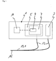
- In 1 1 is a schematic of a device 1 for detecting optical radiation, which is described in the present exemplary embodiment as autofluorescence or a fluorescence of an absorbing substance in the range of an excitation wavelength that corresponds in intensity to autofluorescence, but can also relate to other optical radiation.
- This device 1 comprises a device 3 for generating an optical excitation pulse and a device 5 for receiving an optical measurement signal from the absorbing substance in the area of the excitation pulse.
- the device 3 is a short-pulse laser. With this it is achieved that the excitation pulse interacts exclusively with the material to be examined in a period of time, which can be between a few nanoseconds and less than one nanosecond, depending on the application. As a result, all absorbing molecules in the irradiated volume are very likely to be excited only once and accordingly fluoresce only once at most. Since the fluorescence occurs immediately after the excitation, a fluorescence signal is generated whose time course, depending on the fluorescence lifetime of the corresponding molecules, is only a few nanometers long. The signal consists of a superimposition of the autofluorescence of all fluorescent molecules in the excited volume.
- the optical signals generated, for example, by autofluorescence generally have a very low intensity.
- the device 1 comprises a device 5 for receiving an optical measurement signal from the substance absorbing in the range of the excitation pulse or the excitation wavelength and a converter 7 which converts such a received optical signal into an electrical signal and processes the electrical signal.
- the converter 7 comprises an amplifying photoelement, for example a photomultiplier.
- a pulse of light hitting the photocathode of the photomultiplier generates free electrons, which are multiplied by high-voltage coupled dynodes.
- At the output of the photomultiplier an amplified, negative, needle-shaped voltage pulse proportional to the energy of the light pulse is available for further signal processing.
- fluorescence signals can be evaluated over a very wide range of intensities.
- the converter 7 also comprises a pulse amplifier 9.
- the pulse amplifier 9 prepares the electrical output signal, for example from the photomultiplier, for analysis.
- the pulse amplifier 9 has a 3-stage structure. The first stage inverts the needle-shaped photomultiplier output signal. In the two following stages, the electrical signal is amplified and processed by electronic circuitry (not shown). The processing converts the electrical signal from the converter 7 into a time-expanded signal. In order to achieve the smallest possible change in the fluorescence pulse shape within the signal path due to line inductances and line capacitances, the pulse amplifier 9 is positioned directly on the photomultiplier.
- the device 1 also includes a microcontroller 11, which taps the analog value of the pulse amplifier 9 at a constant time interval after recording the optical signal of the autofluorescence or corresponding fluorescence of low intensity. To do this, a separate circuit (not shown) generates an electrical pulse (read pulse) that triggers an interrupt. In the associated interrupt service routine (ISR), the analog value present at the pulse amplifier 9 is called up by the microcontroller 11 and digitized.
- a microcontroller 11 taps the analog value of the pulse amplifier 9 at a constant time interval after recording the optical signal of the autofluorescence or corresponding fluorescence of low intensity.
- a separate circuit (not shown) generates an electrical pulse (read pulse) that triggers an interrupt.
- ISR interrupt service routine
- the device 5 for receiving an optical measuring signal from the substance absorbing in the range of the excitation wavelength has an optical waveguide - probe 13, which has a ferrule 15 at one end 13.1.
- the digitized voltage values are proportional to the values of the radiant energy of the autofluorescence or corresponding low-intensity fluorescence using a calibration algorithm, normalized and scaled on a scale from 0 to 10 6 . They can then be saved as an RFU (relative fluorescence unit) and shown on a display.
- RFU relative fluorescence unit
Landscapes
- Health & Medical Sciences (AREA)
- Life Sciences & Earth Sciences (AREA)
- Biochemistry (AREA)
- Nuclear Medicine, Radiotherapy & Molecular Imaging (AREA)
- Physics & Mathematics (AREA)
- Chemical & Material Sciences (AREA)
- Analytical Chemistry (AREA)
- General Health & Medical Sciences (AREA)
- General Physics & Mathematics (AREA)
- Immunology (AREA)
- Pathology (AREA)
- Biomedical Technology (AREA)
- Molecular Biology (AREA)
- Engineering & Computer Science (AREA)
- Investigating, Analyzing Materials By Fluorescence Or Luminescence (AREA)
Claims (7)
- Procédé de saisie d'un rayonnement de fluorescence optique, qui est émis par un objet à analyser en tant que signal de mesure optique avec une intensité, qui correspond à une autofluorescence de l'objet, sachant qu'une impulsion d'excitation optique est produite par un laser à impulsions courtes et le signal de mesure optique est converti en un signal électrique et est électriquement traité,
caractérisé en ce que
le signal électrique est allongé dans le temps dans la phase du traitement électrique. - Procédé selon la revendication 1,
caractérisé en ce qu'
un paramètre de l'impulsion d'excitation optique est établi en fonction de la substance de telle manière que des molécules absorbant l'impulsion d'excitation optique sont excitées une fois dans le volume irradié de l'objet. - Procédé selon la revendication 1 ou 2,
caractérisée en ce qu'
un signal de mesure pouvant être saisi, est produit dans le volume irradié, par la superposition d'un signal de mesure optique de toutes les molécules excitées de la substance. - Procédé selon l'une quelconque des revendications précédentes,
caractérisé en ce qu'
une impulsion d'excitation optique est produite avec le laser à impulsions courtes, laquelle interagit avec la substance absorbante dans une période de temps de 0,1 à 1,5 nanosecondes. - Dispositif (1) pour la saisie d'un rayonnement de fluorescence optique, qui est émis par un objet à analyser sous la forme de signal de mesure optique avec une intensité, qui correspond à une autofluorescence de l'objet, avec un laser à impulsions courtes (3), qui produit une impulsion d'excitation optique, avec un équipement (5) pour la réception d'un signal de mesure optique et avec un microcontrôleur, sachant que l'équipement (5) pour la réception du signal de mesure optique comprend un transducteur (7) comprenant un amplificateur de signal (9) pour la conversion du signal de mesure optique reçu en un signal électrique,
caractérisé en ce que
le transducteur (7) allonge dans le temps le signal électrique produit à partir du signal de mesure optique et le microcontrôleur (11) prélève le signal amplifié dans l'amplificateur de signal (9) et allongé dans le temps dans un intervalle constant dans le temps après la réception du signal de mesure optique. - Dispositif selon la revendication 5,
caractérisé en ce que
le transducteur (7) est constitué de telle manière que celui-ci convertit le signal optique en un signal électrique avec une longueur d'au moins la longueur de l'impulsion d'excitation optique. - Procédé selon l'une quelconque des revendications 5 ou 6,
caractérisé en ce que
l'équipement (5) de réception d'un signal de mesure optique de la substance absorbante dans la gamme des paramètres de l'impulsion d'excitation optique, comprend une sonde à fibres optiques (13), qui comporte une ferrule (15) à une extrémité (13.1).
Priority Applications (1)
| Application Number | Priority Date | Filing Date | Title |
|---|---|---|---|
| EP19000370.7A EP3772645B1 (fr) | 2019-08-09 | 2019-08-09 | Procédé et dispositif de détection d'une très faible fluorescence |
Applications Claiming Priority (1)
| Application Number | Priority Date | Filing Date | Title |
|---|---|---|---|
| EP19000370.7A EP3772645B1 (fr) | 2019-08-09 | 2019-08-09 | Procédé et dispositif de détection d'une très faible fluorescence |
Publications (2)
| Publication Number | Publication Date |
|---|---|
| EP3772645A1 EP3772645A1 (fr) | 2021-02-10 |
| EP3772645B1 true EP3772645B1 (fr) | 2023-02-08 |
Family
ID=67614411
Family Applications (1)
| Application Number | Title | Priority Date | Filing Date |
|---|---|---|---|
| EP19000370.7A Active EP3772645B1 (fr) | 2019-08-09 | 2019-08-09 | Procédé et dispositif de détection d'une très faible fluorescence |
Country Status (1)
| Country | Link |
|---|---|
| EP (1) | EP3772645B1 (fr) |
Families Citing this family (1)
| Publication number | Priority date | Publication date | Assignee | Title |
|---|---|---|---|---|
| CN116067934B (zh) * | 2023-03-28 | 2023-07-18 | 赛默飞世尔(上海)仪器有限公司 | 用于信号采集的方法和设备 |
Family Cites Families (7)
| Publication number | Priority date | Publication date | Assignee | Title |
|---|---|---|---|---|
| DE4420572C2 (de) * | 1994-06-03 | 1999-02-04 | Hartmut Dr Rer Nat Lucht | Vorrichtung zur Bestimmung der Konzentration von fluoreszierenden Stoffen |
| DE19920158A1 (de) * | 1999-04-29 | 2000-11-02 | Univ Schiller Jena | Verfahren und Anordnung zur Bestimmung von Fluorophoren an Objekten, insbesondere am lebenden Augenhintergrund |
| WO2002069784A2 (fr) * | 2001-03-01 | 2002-09-12 | Trustees Of Dartmouth College | Spectrometre a fluorescence permanente (fls) et methodes de detection de tissus malades |
| DE102005021205B4 (de) * | 2005-05-07 | 2007-08-16 | Mfd Diagnostics Gmbh | Verfahren und Anordnung zur lokalen Erfassung der Vitalität von lebenden Zellen in Zellkulturen oder im Gewebe |
| EP2336751B1 (fr) * | 2009-12-16 | 2014-09-10 | Fraunhofer-Gesellschaft zur Förderung der angewandten Forschung e.V. | Procédé de détermination du sexe d'oeufs d'oiseaux |
| US8455845B2 (en) * | 2010-08-23 | 2013-06-04 | Saudi Arabian Oil Company | Method for detecting drag reducer additives in gasoline |
| IT201700028787A1 (it) * | 2017-03-15 | 2018-09-15 | Fondazione St Italiano Tecnologia | Sistema e metodo per raccolta di luce assialmente risolta attraverso una guida d'onda rastremata. |
-
2019
- 2019-08-09 EP EP19000370.7A patent/EP3772645B1/fr active Active
Also Published As
| Publication number | Publication date |
|---|---|
| EP3772645A1 (fr) | 2021-02-10 |
Similar Documents
| Publication | Publication Date | Title |
|---|---|---|
| DE69030581T2 (de) | Verfahren zur untersuchung von gegeständen makromolekularer grösse | |
| DE102008018476B4 (de) | Mikroskopievorrichtung | |
| EP0706671A1 (fr) | Procede de microscopie a balayage a luminescence et microscope a balayage a luminescence | |
| DE3511758A1 (de) | Vorrichtung zur fluoreszenzspektralanalyse | |
| EP0056426A2 (fr) | Dispositif pour la représentation de paramètres d'un échantillon | |
| EP3752818B1 (fr) | Procédé de microscopie à durée de vie de fluorescence avec comptage de photons individuels corrélé dans le temps | |
| DE102011055272A1 (de) | Verfahren zur Bestimmung eines relaxationszeitabhängigen Parameters zu einem System | |
| DE102008012635A1 (de) | Verfahren und Anordnung zur zeitaufgelösten Spektroskopie | |
| DE102009015341A1 (de) | Verfahren und Vorrichtungen zur optischen Untersuchung von Proben | |
| DE102024112112A1 (de) | Verfahren und vorrichtung zur erfassung einzelner photonen aus einer probe mit mindestens einem emitter | |
| EP3772645B1 (fr) | Procédé et dispositif de détection d'une très faible fluorescence | |
| EP3649448B1 (fr) | Procédé de comptage de photons au moyen d'un photomultiplicateur | |
| DE19702914C2 (de) | Verfahren und Anordnung zum Bestimmen vorgegebener Eigenschaften von Zielpartikeln eines Probenmediums | |
| DE112013005632T5 (de) | Rastersondenmikroskop und Probenbeobachtungsverfahren unter Verwendung desselben | |
| DE202013102039U1 (de) | STED-Vorrichtung | |
| EP1141762A1 (fr) | Procede pour rechercher de maniere differenciee differentes structures de preference dans des preparations biologiques | |
| DE102009053306B4 (de) | Verfahren und Vorrichtung zur Erzeugung einer Anregungsstrahlung und Einrichtung zur Analyse einer Probe | |
| EP1815269B1 (fr) | Procede pour la separation des signaux dans des detecteurs a scintillation | |
| DE102012219136A1 (de) | Mikroskop und ein Verfahren zur Untersuchung einer Probe mit einem Mikroskop | |
| DE102004015946B3 (de) | Vorrichtung und Verfahren zur Raman-spektroskopischen Charakterisierung eines Prozessmediums | |
| DE4429383A1 (de) | Verfahren und Vorrichtung zur zeit- und ortsaufgelösten Fluoreszenz- bzw. Streulicht-Spektroskopie | |
| DE9421717U1 (de) | Vorrichtung zur zeit- und ortsaufgelösten Fluoreszenz- bzw. Streulicht-Spektroskopie | |
| DE10250013B4 (de) | Optisches Materialanalyseverfahren für Materialproben und Vorrichtung zur Durchführung des Verfahrens | |
| DE19939574B4 (de) | Verfahren zur dreidimensionalen Objektabtastung | |
| DE102010036082B4 (de) | Mikrofluidischer Messaufbau und optisches Analyseverfahren zur optischen Analyse von Zellen |
Legal Events
| Date | Code | Title | Description |
|---|---|---|---|
| PUAI | Public reference made under article 153(3) epc to a published international application that has entered the european phase |
Free format text: ORIGINAL CODE: 0009012 |
|
| STAA | Information on the status of an ep patent application or granted ep patent |
Free format text: STATUS: THE APPLICATION HAS BEEN PUBLISHED |
|
| AK | Designated contracting states |
Kind code of ref document: A1 Designated state(s): AL AT BE BG CH CY CZ DE DK EE ES FI FR GB GR HR HU IE IS IT LI LT LU LV MC MK MT NL NO PL PT RO RS SE SI SK SM TR |
|
| AX | Request for extension of the european patent |
Extension state: BA ME |
|
| STAA | Information on the status of an ep patent application or granted ep patent |
Free format text: STATUS: REQUEST FOR EXAMINATION WAS MADE |
|
| 17P | Request for examination filed |
Effective date: 20210809 |
|
| RBV | Designated contracting states (corrected) |
Designated state(s): AL AT BE BG CH CY CZ DE DK EE ES FI FR GB GR HR HU IE IS IT LI LT LU LV MC MK MT NL NO PL PT RO RS SE SI SK SM TR |
|
| GRAP | Despatch of communication of intention to grant a patent |
Free format text: ORIGINAL CODE: EPIDOSNIGR1 |
|
| STAA | Information on the status of an ep patent application or granted ep patent |
Free format text: STATUS: GRANT OF PATENT IS INTENDED |
|
| INTG | Intention to grant announced |
Effective date: 20220913 |
|
| GRAS | Grant fee paid |
Free format text: ORIGINAL CODE: EPIDOSNIGR3 |
|
| GRAA | (expected) grant |
Free format text: ORIGINAL CODE: 0009210 |
|
| STAA | Information on the status of an ep patent application or granted ep patent |
Free format text: STATUS: THE PATENT HAS BEEN GRANTED |
|
| AK | Designated contracting states |
Kind code of ref document: B1 Designated state(s): AL AT BE BG CH CY CZ DE DK EE ES FI FR GB GR HR HU IE IS IT LI LT LU LV MC MK MT NL NO PL PT RO RS SE SI SK SM TR |
|
| REG | Reference to a national code |
Ref country code: GB Ref legal event code: FG4D Free format text: NOT ENGLISH |
|
| REG | Reference to a national code |
Ref country code: CH Ref legal event code: EP Ref country code: AT Ref legal event code: REF Ref document number: 1547577 Country of ref document: AT Kind code of ref document: T Effective date: 20230215 |
|
| REG | Reference to a national code |
Ref country code: DE Ref legal event code: R096 Ref document number: 502019006937 Country of ref document: DE |
|
| REG | Reference to a national code |
Ref country code: IE Ref legal event code: FG4D Free format text: LANGUAGE OF EP DOCUMENT: GERMAN |
|
| REG | Reference to a national code |
Ref country code: LT Ref legal event code: MG9D |
|
| REG | Reference to a national code |
Ref country code: NL Ref legal event code: MP Effective date: 20230208 |
|
| PG25 | Lapsed in a contracting state [announced via postgrant information from national office to epo] |
Ref country code: RS Free format text: LAPSE BECAUSE OF FAILURE TO SUBMIT A TRANSLATION OF THE DESCRIPTION OR TO PAY THE FEE WITHIN THE PRESCRIBED TIME-LIMIT Effective date: 20230208 Ref country code: PT Free format text: LAPSE BECAUSE OF FAILURE TO SUBMIT A TRANSLATION OF THE DESCRIPTION OR TO PAY THE FEE WITHIN THE PRESCRIBED TIME-LIMIT Effective date: 20230609 Ref country code: NO Free format text: LAPSE BECAUSE OF FAILURE TO SUBMIT A TRANSLATION OF THE DESCRIPTION OR TO PAY THE FEE WITHIN THE PRESCRIBED TIME-LIMIT Effective date: 20230508 Ref country code: NL Free format text: LAPSE BECAUSE OF FAILURE TO SUBMIT A TRANSLATION OF THE DESCRIPTION OR TO PAY THE FEE WITHIN THE PRESCRIBED TIME-LIMIT Effective date: 20230208 Ref country code: LV Free format text: LAPSE BECAUSE OF FAILURE TO SUBMIT A TRANSLATION OF THE DESCRIPTION OR TO PAY THE FEE WITHIN THE PRESCRIBED TIME-LIMIT Effective date: 20230208 Ref country code: LT Free format text: LAPSE BECAUSE OF FAILURE TO SUBMIT A TRANSLATION OF THE DESCRIPTION OR TO PAY THE FEE WITHIN THE PRESCRIBED TIME-LIMIT Effective date: 20230208 Ref country code: HR Free format text: LAPSE BECAUSE OF FAILURE TO SUBMIT A TRANSLATION OF THE DESCRIPTION OR TO PAY THE FEE WITHIN THE PRESCRIBED TIME-LIMIT Effective date: 20230208 Ref country code: ES Free format text: LAPSE BECAUSE OF FAILURE TO SUBMIT A TRANSLATION OF THE DESCRIPTION OR TO PAY THE FEE WITHIN THE PRESCRIBED TIME-LIMIT Effective date: 20230208 |
|
| PG25 | Lapsed in a contracting state [announced via postgrant information from national office to epo] |
Ref country code: SE Free format text: LAPSE BECAUSE OF FAILURE TO SUBMIT A TRANSLATION OF THE DESCRIPTION OR TO PAY THE FEE WITHIN THE PRESCRIBED TIME-LIMIT Effective date: 20230208 Ref country code: PL Free format text: LAPSE BECAUSE OF FAILURE TO SUBMIT A TRANSLATION OF THE DESCRIPTION OR TO PAY THE FEE WITHIN THE PRESCRIBED TIME-LIMIT Effective date: 20230208 Ref country code: IS Free format text: LAPSE BECAUSE OF FAILURE TO SUBMIT A TRANSLATION OF THE DESCRIPTION OR TO PAY THE FEE WITHIN THE PRESCRIBED TIME-LIMIT Effective date: 20230608 Ref country code: GR Free format text: LAPSE BECAUSE OF FAILURE TO SUBMIT A TRANSLATION OF THE DESCRIPTION OR TO PAY THE FEE WITHIN THE PRESCRIBED TIME-LIMIT Effective date: 20230509 Ref country code: FI Free format text: LAPSE BECAUSE OF FAILURE TO SUBMIT A TRANSLATION OF THE DESCRIPTION OR TO PAY THE FEE WITHIN THE PRESCRIBED TIME-LIMIT Effective date: 20230208 |
|
| PG25 | Lapsed in a contracting state [announced via postgrant information from national office to epo] |
Ref country code: SM Free format text: LAPSE BECAUSE OF FAILURE TO SUBMIT A TRANSLATION OF THE DESCRIPTION OR TO PAY THE FEE WITHIN THE PRESCRIBED TIME-LIMIT Effective date: 20230208 Ref country code: RO Free format text: LAPSE BECAUSE OF FAILURE TO SUBMIT A TRANSLATION OF THE DESCRIPTION OR TO PAY THE FEE WITHIN THE PRESCRIBED TIME-LIMIT Effective date: 20230208 Ref country code: EE Free format text: LAPSE BECAUSE OF FAILURE TO SUBMIT A TRANSLATION OF THE DESCRIPTION OR TO PAY THE FEE WITHIN THE PRESCRIBED TIME-LIMIT Effective date: 20230208 Ref country code: DK Free format text: LAPSE BECAUSE OF FAILURE TO SUBMIT A TRANSLATION OF THE DESCRIPTION OR TO PAY THE FEE WITHIN THE PRESCRIBED TIME-LIMIT Effective date: 20230208 Ref country code: CZ Free format text: LAPSE BECAUSE OF FAILURE TO SUBMIT A TRANSLATION OF THE DESCRIPTION OR TO PAY THE FEE WITHIN THE PRESCRIBED TIME-LIMIT Effective date: 20230208 |
|
| REG | Reference to a national code |
Ref country code: DE Ref legal event code: R097 Ref document number: 502019006937 Country of ref document: DE |
|
| PG25 | Lapsed in a contracting state [announced via postgrant information from national office to epo] |
Ref country code: SK Free format text: LAPSE BECAUSE OF FAILURE TO SUBMIT A TRANSLATION OF THE DESCRIPTION OR TO PAY THE FEE WITHIN THE PRESCRIBED TIME-LIMIT Effective date: 20230208 |
|
| PLBE | No opposition filed within time limit |
Free format text: ORIGINAL CODE: 0009261 |
|
| STAA | Information on the status of an ep patent application or granted ep patent |
Free format text: STATUS: NO OPPOSITION FILED WITHIN TIME LIMIT |
|
| 26N | No opposition filed |
Effective date: 20231109 |
|
| PG25 | Lapsed in a contracting state [announced via postgrant information from national office to epo] |
Ref country code: SI Free format text: LAPSE BECAUSE OF FAILURE TO SUBMIT A TRANSLATION OF THE DESCRIPTION OR TO PAY THE FEE WITHIN THE PRESCRIBED TIME-LIMIT Effective date: 20230208 |
|
| PG25 | Lapsed in a contracting state [announced via postgrant information from national office to epo] |
Ref country code: MC Free format text: LAPSE BECAUSE OF FAILURE TO SUBMIT A TRANSLATION OF THE DESCRIPTION OR TO PAY THE FEE WITHIN THE PRESCRIBED TIME-LIMIT Effective date: 20230208 |
|
| REG | Reference to a national code |
Ref country code: CH Ref legal event code: PL |
|
| PG25 | Lapsed in a contracting state [announced via postgrant information from national office to epo] |
Ref country code: MC Free format text: LAPSE BECAUSE OF FAILURE TO SUBMIT A TRANSLATION OF THE DESCRIPTION OR TO PAY THE FEE WITHIN THE PRESCRIBED TIME-LIMIT Effective date: 20230208 |
|
| PG25 | Lapsed in a contracting state [announced via postgrant information from national office to epo] |
Ref country code: LU Free format text: LAPSE BECAUSE OF NON-PAYMENT OF DUE FEES Effective date: 20230809 |
|
| GBPC | Gb: european patent ceased through non-payment of renewal fee |
Effective date: 20230809 |
|
| PG25 | Lapsed in a contracting state [announced via postgrant information from national office to epo] |
Ref country code: LU Free format text: LAPSE BECAUSE OF NON-PAYMENT OF DUE FEES Effective date: 20230809 Ref country code: CH Free format text: LAPSE BECAUSE OF NON-PAYMENT OF DUE FEES Effective date: 20230831 |
|
| REG | Reference to a national code |
Ref country code: BE Ref legal event code: MM Effective date: 20230831 |
|
| REG | Reference to a national code |
Ref country code: IE Ref legal event code: MM4A |
|
| PG25 | Lapsed in a contracting state [announced via postgrant information from national office to epo] |
Ref country code: IT Free format text: LAPSE BECAUSE OF FAILURE TO SUBMIT A TRANSLATION OF THE DESCRIPTION OR TO PAY THE FEE WITHIN THE PRESCRIBED TIME-LIMIT Effective date: 20230208 |
|
| PG25 | Lapsed in a contracting state [announced via postgrant information from national office to epo] |
Ref country code: IE Free format text: LAPSE BECAUSE OF NON-PAYMENT OF DUE FEES Effective date: 20230809 |
|
| PG25 | Lapsed in a contracting state [announced via postgrant information from national office to epo] |
Ref country code: GB Free format text: LAPSE BECAUSE OF NON-PAYMENT OF DUE FEES Effective date: 20230809 |
|
| PG25 | Lapsed in a contracting state [announced via postgrant information from national office to epo] |
Ref country code: IE Free format text: LAPSE BECAUSE OF NON-PAYMENT OF DUE FEES Effective date: 20230809 Ref country code: GB Free format text: LAPSE BECAUSE OF NON-PAYMENT OF DUE FEES Effective date: 20230809 Ref country code: FR Free format text: LAPSE BECAUSE OF NON-PAYMENT OF DUE FEES Effective date: 20230831 |
|
| PG25 | Lapsed in a contracting state [announced via postgrant information from national office to epo] |
Ref country code: BE Free format text: LAPSE BECAUSE OF NON-PAYMENT OF DUE FEES Effective date: 20230831 |
|
| PG25 | Lapsed in a contracting state [announced via postgrant information from national office to epo] |
Ref country code: BG Free format text: LAPSE BECAUSE OF FAILURE TO SUBMIT A TRANSLATION OF THE DESCRIPTION OR TO PAY THE FEE WITHIN THE PRESCRIBED TIME-LIMIT Effective date: 20230208 |
|
| PG25 | Lapsed in a contracting state [announced via postgrant information from national office to epo] |
Ref country code: BG Free format text: LAPSE BECAUSE OF FAILURE TO SUBMIT A TRANSLATION OF THE DESCRIPTION OR TO PAY THE FEE WITHIN THE PRESCRIBED TIME-LIMIT Effective date: 20230208 |
|
| PG25 | Lapsed in a contracting state [announced via postgrant information from national office to epo] |
Ref country code: CY Free format text: LAPSE BECAUSE OF FAILURE TO SUBMIT A TRANSLATION OF THE DESCRIPTION OR TO PAY THE FEE WITHIN THE PRESCRIBED TIME-LIMIT; INVALID AB INITIO Effective date: 20190809 |
|
| PG25 | Lapsed in a contracting state [announced via postgrant information from national office to epo] |
Ref country code: HU Free format text: LAPSE BECAUSE OF FAILURE TO SUBMIT A TRANSLATION OF THE DESCRIPTION OR TO PAY THE FEE WITHIN THE PRESCRIBED TIME-LIMIT; INVALID AB INITIO Effective date: 20190809 |
|
| PGFP | Annual fee paid to national office [announced via postgrant information from national office to epo] |
Ref country code: DE Payment date: 20250827 Year of fee payment: 7 |
|
| REG | Reference to a national code |
Ref country code: AT Ref legal event code: MM01 Ref document number: 1547577 Country of ref document: AT Kind code of ref document: T Effective date: 20240809 |
|
| PG25 | Lapsed in a contracting state [announced via postgrant information from national office to epo] |
Ref country code: AT Free format text: LAPSE BECAUSE OF NON-PAYMENT OF DUE FEES Effective date: 20240809 |
|
| PG25 | Lapsed in a contracting state [announced via postgrant information from national office to epo] |
Ref country code: TR Free format text: LAPSE BECAUSE OF FAILURE TO SUBMIT A TRANSLATION OF THE DESCRIPTION OR TO PAY THE FEE WITHIN THE PRESCRIBED TIME-LIMIT Effective date: 20230208 |
|
| PGFP | Annual fee paid to national office [announced via postgrant information from national office to epo] |
Ref country code: AT Payment date: 20260410 Year of fee payment: 5 |