EP3772645B1 - Method and device for detecting very low fluorescence - Google Patents
Method and device for detecting very low fluorescence Download PDFInfo
- Publication number
- EP3772645B1 EP3772645B1 EP19000370.7A EP19000370A EP3772645B1 EP 3772645 B1 EP3772645 B1 EP 3772645B1 EP 19000370 A EP19000370 A EP 19000370A EP 3772645 B1 EP3772645 B1 EP 3772645B1
- Authority
- EP
- European Patent Office
- Prior art keywords
- optical
- signal
- measurement signal
- optical measurement
- excitation pulse
- Prior art date
- Legal status (The legal status is an assumption and is not a legal conclusion. Google has not performed a legal analysis and makes no representation as to the accuracy of the status listed.)
- Active
Links
Images
Classifications
-
- G—PHYSICS
- G01—MEASURING; TESTING
- G01N—INVESTIGATING OR ANALYSING MATERIALS BY DETERMINING THEIR CHEMICAL OR PHYSICAL PROPERTIES
- G01N21/00—Investigating or analysing materials by the use of optical means, i.e. using sub-millimetre waves, infrared, visible or ultraviolet light
- G01N21/62—Systems in which the material investigated is excited whereby it emits light or causes a change in wavelength of the incident light
- G01N21/63—Systems in which the material investigated is excited whereby it emits light or causes a change in wavelength of the incident light optically excited
- G01N21/64—Fluorescence; Phosphorescence
- G01N21/6486—Measuring fluorescence of biological material, e.g. DNA, RNA, cells
-
- G—PHYSICS
- G01—MEASURING; TESTING
- G01N—INVESTIGATING OR ANALYSING MATERIALS BY DETERMINING THEIR CHEMICAL OR PHYSICAL PROPERTIES
- G01N21/00—Investigating or analysing materials by the use of optical means, i.e. using sub-millimetre waves, infrared, visible or ultraviolet light
- G01N21/62—Systems in which the material investigated is excited whereby it emits light or causes a change in wavelength of the incident light
- G01N21/63—Systems in which the material investigated is excited whereby it emits light or causes a change in wavelength of the incident light optically excited
- G01N21/64—Fluorescence; Phosphorescence
- G01N21/6408—Fluorescence; Phosphorescence with measurement of decay time, time resolved fluorescence
-
- G—PHYSICS
- G01—MEASURING; TESTING
- G01N—INVESTIGATING OR ANALYSING MATERIALS BY DETERMINING THEIR CHEMICAL OR PHYSICAL PROPERTIES
- G01N21/00—Investigating or analysing materials by the use of optical means, i.e. using sub-millimetre waves, infrared, visible or ultraviolet light
- G01N21/62—Systems in which the material investigated is excited whereby it emits light or causes a change in wavelength of the incident light
- G01N21/63—Systems in which the material investigated is excited whereby it emits light or causes a change in wavelength of the incident light optically excited
- G01N21/64—Fluorescence; Phosphorescence
- G01N21/645—Specially adapted constructive features of fluorimeters
- G01N2021/6484—Optical fibres
Definitions
- the present invention relates to a method for detecting an optical fluorescence radiation emitted by an object to be examined as an optical measurement signal with an intensity that corresponds to an autofluorescence of the object, an optical excitation pulse being generated by a short-pulse laser and the optical measurement signal being processed electrically , and a device for detecting optical fluorescence radiation, which is emitted by an object to be examined as an optical measurement signal with an intensity that corresponds to an autofluorescence of the object, with a short-pulse laser that generates an optical excitation pulse and with a device for receiving an optical measurement signal , wherein the device for receiving the optical measurement signal comprises a converter for converting the received optical measurement signal into an electrical signal and a signal amplifier.
- optical analyzes are only possible on the tissue surface, on thin tissue sections or in a spectral range in which the tissue shows a high transmission of light.
- Fluorescence microscopy is a proven method of analyzing organic tissue using fluorescence technology.
- NIR near-infrared spectral range
- a technical approach that uses the NIR transparency of tissue to excite autofluorescence is multiphoton spectroscopy.
- an intensive NIR laser beam is focused into the tissue to be analyzed.
- multi-photon processes e.g. two-photon absorption
- Molecules whose absorption bands are in the lower optical wavelength range can also be excited to fluoresce through the multiphoton process.
- the multi-photon technique has two major disadvantages: On the one hand, the very high optical energy density leads to severe bleaching of the tissue. The fluorescent molecules are changed or destroyed in the process. A correct quantitative analysis of fluorophore changes can therefore not be guaranteed by these techniques.
- the object of the present invention is therefore to further develop a method and a device of the type mentioned at the outset in such a way that fluorescence signals of very low intensity, which are predominantly but not exclusively of biological origin, can be detected and processed in a technically simpler manner.
- the object of the method is achieved in that the electrical signal is time-expanded in the electrical processing step.
- the object is achieved according to the invention in that the converter temporally expands the electrical signal generated from the optical measurement signal and a microcontroller (11) transmits the electrical and temporally expanded signal amplified in the signal amplifier (9) at a constant time interval after receipt of the picks up the optical measurement signal.
- the most important advantage compared to linear fluorescence spectroscopy is the higher signal-to-noise ratio due to the use of very short, intense excitation pulses in connection with signal amplification, e.g. the photomultiplier. This makes it possible to detect fluorescence signals of very low intensity (eg autofluorescence) in real time.
- the automatic adjustment of a dynode voltage offers a very large amplification range, so that Fluorescence signals can be measured in a very wide intensity range or strong intensity fluctuations.
- the process considered here requires much less technical effort.
- the device of the present invention can be greatly miniaturized and developed as a mobile analysis device.
- One advantage of the present invention is that the method and the device can be used to generate and detect optical signals of autofluorescence or of a fluorescence of the substances absorbing in the range of the excitation wavelength that corresponds in intensity to the autofluorescence.
- the analysis of chemical substance states or of chemical and physical processes can be carried out on the basis of the fluorescence of individual substance components without the disadvantages of the prior art.
- a further advantage of the present invention is that the optical parameters of the excitation pulse are set as a function of the substance in such a way that there is a very high probability that absorbing molecules of the substance in the irradiated volume will be excited once. This feature makes it possible to obtain very accurate signals for analyzing a substance.
- a further advantage of the present invention is that the device for receiving an optical measurement signal comprises a converter for converting the received optical measurement signal into an electrical signal and that this converts the optical measurement signal into a time-expanded electrical signal with a length of at least the length of the optical excitation pulse converts.
- the conversion of the optical measurement signal into a time-extended electrical signal and the processing of the same contributes to improving the analysis of the substance to be examined.
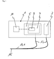
- In 1 1 is a schematic of a device 1 for detecting optical radiation, which is described in the present exemplary embodiment as autofluorescence or a fluorescence of an absorbing substance in the range of an excitation wavelength that corresponds in intensity to autofluorescence, but can also relate to other optical radiation.
- This device 1 comprises a device 3 for generating an optical excitation pulse and a device 5 for receiving an optical measurement signal from the absorbing substance in the area of the excitation pulse.
- the device 3 is a short-pulse laser. With this it is achieved that the excitation pulse interacts exclusively with the material to be examined in a period of time, which can be between a few nanoseconds and less than one nanosecond, depending on the application. As a result, all absorbing molecules in the irradiated volume are very likely to be excited only once and accordingly fluoresce only once at most. Since the fluorescence occurs immediately after the excitation, a fluorescence signal is generated whose time course, depending on the fluorescence lifetime of the corresponding molecules, is only a few nanometers long. The signal consists of a superimposition of the autofluorescence of all fluorescent molecules in the excited volume.
- the optical signals generated, for example, by autofluorescence generally have a very low intensity.
- the device 1 comprises a device 5 for receiving an optical measurement signal from the substance absorbing in the range of the excitation pulse or the excitation wavelength and a converter 7 which converts such a received optical signal into an electrical signal and processes the electrical signal.
- the converter 7 comprises an amplifying photoelement, for example a photomultiplier.
- a pulse of light hitting the photocathode of the photomultiplier generates free electrons, which are multiplied by high-voltage coupled dynodes.
- At the output of the photomultiplier an amplified, negative, needle-shaped voltage pulse proportional to the energy of the light pulse is available for further signal processing.
- fluorescence signals can be evaluated over a very wide range of intensities.
- the converter 7 also comprises a pulse amplifier 9.
- the pulse amplifier 9 prepares the electrical output signal, for example from the photomultiplier, for analysis.
- the pulse amplifier 9 has a 3-stage structure. The first stage inverts the needle-shaped photomultiplier output signal. In the two following stages, the electrical signal is amplified and processed by electronic circuitry (not shown). The processing converts the electrical signal from the converter 7 into a time-expanded signal. In order to achieve the smallest possible change in the fluorescence pulse shape within the signal path due to line inductances and line capacitances, the pulse amplifier 9 is positioned directly on the photomultiplier.
- the device 1 also includes a microcontroller 11, which taps the analog value of the pulse amplifier 9 at a constant time interval after recording the optical signal of the autofluorescence or corresponding fluorescence of low intensity. To do this, a separate circuit (not shown) generates an electrical pulse (read pulse) that triggers an interrupt. In the associated interrupt service routine (ISR), the analog value present at the pulse amplifier 9 is called up by the microcontroller 11 and digitized.
- a microcontroller 11 taps the analog value of the pulse amplifier 9 at a constant time interval after recording the optical signal of the autofluorescence or corresponding fluorescence of low intensity.
- a separate circuit (not shown) generates an electrical pulse (read pulse) that triggers an interrupt.
- ISR interrupt service routine
- the device 5 for receiving an optical measuring signal from the substance absorbing in the range of the excitation wavelength has an optical waveguide - probe 13, which has a ferrule 15 at one end 13.1.
- the digitized voltage values are proportional to the values of the radiant energy of the autofluorescence or corresponding low-intensity fluorescence using a calibration algorithm, normalized and scaled on a scale from 0 to 10 6 . They can then be saved as an RFU (relative fluorescence unit) and shown on a display.
- RFU relative fluorescence unit
Landscapes
- Health & Medical Sciences (AREA)
- Life Sciences & Earth Sciences (AREA)
- Biochemistry (AREA)
- Nuclear Medicine, Radiotherapy & Molecular Imaging (AREA)
- Physics & Mathematics (AREA)
- Chemical & Material Sciences (AREA)
- Analytical Chemistry (AREA)
- General Health & Medical Sciences (AREA)
- General Physics & Mathematics (AREA)
- Immunology (AREA)
- Pathology (AREA)
- Biomedical Technology (AREA)
- Molecular Biology (AREA)
- Engineering & Computer Science (AREA)
- Investigating, Analyzing Materials By Fluorescence Or Luminescence (AREA)
Description
Die vorliegende Erfindung betrifft ein Verfahren zur Erfassung einer optischen Fluoreszenzstrahlung, die von einem zu untersuchenden Objekt als optisches Messsignal mit einer Intensität abgestrahlt wird, die einer Autofluoreszenz des Objekts entspricht, wobei ein optischer Anregungsimpuls durch einen Kurzpulslaser erzeugt wird und das optische Messignal elektrisch verarbeitet wird, und eine Vorrichtung zur Erfassung einer optischen Fluoreszenzstrahlung, die von einem zu untersuchenden Objekt als optisches Messsignal mit einer Intensität abgestrahlt wird, die einer Autofluoreszenz des Objekts entspricht, mit einem Kurzpulslaser, der einen optischen Anregungsimpuls erzeugt und mit einer Einrichtung zum Empfang eines optischen Messignals, wobei die Einrichtung zum Empfang des optischen Messignals einen Wandler zur Umwandlung des empfangenen optischen Messignals in ein elektrisches Signal und einen Signalverstärker umfasst.The present invention relates to a method for detecting an optical fluorescence radiation emitted by an object to be examined as an optical measurement signal with an intensity that corresponds to an autofluorescence of the object, an optical excitation pulse being generated by a short-pulse laser and the optical measurement signal being processed electrically , and a device for detecting optical fluorescence radiation, which is emitted by an object to be examined as an optical measurement signal with an intensity that corresponds to an autofluorescence of the object, with a short-pulse laser that generates an optical excitation pulse and with a device for receiving an optical measurement signal , wherein the device for receiving the optical measurement signal comprises a converter for converting the received optical measurement signal into an electrical signal and a signal amplifier.
Die Analyse von chemischen Stoffzuständen bzw. von chemischen und physikalischen Prozessen aufgrund der Fluoreszenz einzelner Bestandteile erfolgt grundsätzlich nach dem folgenden Schema:
- 1. Einstrahlung von Licht in das zu untersuchende Objekt
- Erzeugung des Lichts durch eine Lichtquelle
- ggf. Strahlformung
- ggf. räumliche und spektrale Filterung
- Weiterleitung des Lichts in oder auf das zu untersuchende Objekt
- 2. Analyse des vom Objekt ausgestrahlten Lichts
- Ableitung des vom Objekt ausgestrahlten Lichts
- spektrale Filterung
- Weiterleitung des gefilterten Lichts auf ein photoaktives Element
- Umwandlung des Lichts in ein elektrisches Signal
- ggf. Verstärkung und Integration des elektrischen Signals
- ggf. weitere elektronische Verfahren zur Analyse des Signals Wegen der sehr kurzen Lebensdauer der Fluoreszenz (Piko- bis Nanosekunden) beschränkt sich die Signalauswertung auf eine entsprechend kurze Zeit nach der Anregung. Dadurch hat man die Möglichkeit, nicht nur Stoffzustände zu analysieren, sondern auch dynamische Prozesse zu untersuchen.
- 1. Irradiation of light into the object to be examined
- Generation of light by a light source
- possibly beam shaping
- possibly spatial and spectral filtering
- Transmission of the light into or onto the object to be examined
- 2. Analysis of the light emitted by the object
- Derivation of the light emitted by the object
- spectral filtering
- Transmission of the filtered light to a photoactive element
- Conversion of light into an electrical signal
- if necessary amplification and integration of the electrical signal
- possibly other electronic methods for analyzing the signal Because of the very short lifetime of the fluorescence (picoseconds to nanoseconds), the signal evaluation is limited to a correspondingly short time after the excitation. This makes it possible not only to analyze material states, but also to examine dynamic processes.
Die Erfassung optischer Signale biologischen Ursprungs, insbesondere solcher, die direkt aus dem vitalen Organismus heraus aufgezeichnet werden, ist allerdings immer dadurch begrenzt, dass die Wechselwirkung des Lichts mit dem Gewebe, das den Ort der Messung umgibt, das ursprüngliche Signal verändert oder auslöscht. Ursache dafür sind die Absorption und die Streuung des Lichts im Gewebe. Daher sind optische Analysen entweder nur an der Gewebeoberfläche, an dünnen Gewebeschnitten oder in einem Spektralbereich möglich, bei dem das Gewebe eine hohe Transmission des Lichts zeigt.However, the detection of optical signals of biological origin, in particular those recorded directly from the living organism, is always limited by the fact that the interaction of the light with the tissue surrounding the location of the measurement changes or extinguishes the original signal. This is caused by the absorption and scattering of the light in the tissue. Therefore, optical analyzes are only possible on the tissue surface, on thin tissue sections or in a spectral range in which the tissue shows a high transmission of light.
Ein bewährtes Verfahren der fluoreszenztechnischen Analyse von organischem Gewebe ist die Fluoreszenzmikroskopie.Fluorescence microscopy is a proven method of analyzing organic tissue using fluorescence technology.
Im Nahinfraroten Spektralbereich (NIR) zeigen biologische Gewebe und Materialien eine relativ hohe Transparenz. Dieser Bereich wird daher oft als "Optisches Fenster" im Gewebe bezeichnet. In diesem Bereich ist die Eindringtiefe von Licht daher vergleichsweise hoch. Dementsprechend kann hier eine spektrale Analyse der Veränderungen im Gewebe stattfinden. Allerdings finden sich nur sehr wenige Biomoleküle, die eine Autofluoreszenz im NIR zeigen.In the near-infrared spectral range (NIR), biological tissues and materials show a relatively high level of transparency. This area is therefore often referred to as the "optical window" in the tissue. In this area, the penetration depth of light is therefore comparatively high. Accordingly, a spectral analysis of the changes in the tissue can take place here. However, there are only very few biomolecules that show autofluorescence in the NIR.
Ein technischer Ansatz, der sich die NIR-Transparenz von Gewebe zunutze macht, um damit Autofluoreszenzen anzuregen, ist die Mehrphotonen-Spektroskopie. Hierzu wird ein intensiver NIR-Laserstrahl in das zu analysierende Gewebe fokussiert. Im Fokus des Laserstrahls entsteht eine so hohe optische Energiedichte, dass Mehrphotonenprozesse (z.B. Zwei-Photonen-Absorption) ablaufen, die nicht-linear von der Energiedichte des Lichts abhängen.A technical approach that uses the NIR transparency of tissue to excite autofluorescence is multiphoton spectroscopy. For this purpose, an intensive NIR laser beam is focused into the tissue to be analyzed. In the focus of the laser beam there is such a high optical energy density that multi-photon processes (e.g. two-photon absorption) take place that depend non-linearly on the energy density of the light.
Durch den Mehrphotonenprozess können auch Moleküle zur Fluoreszenz angeregt werden, deren Absorptionsbanden im unteren optischen Wellenlängenbereich liegen.Molecules whose absorption bands are in the lower optical wavelength range can also be excited to fluoresce through the multiphoton process.
Die Mehrphotonen-Technik hat zwei entscheidende Nachteile: Zum einen führt die sehr hohe optische Energiedichte zu einem starken Ausbleichen des Gewebes. Die fluoreszierenden Moleküle werden dabei verändert oder zerstört. Eine korrekte quantitative Analyse von Fluorophor-Änderungen ist daher durch diese Techniken nicht zu gewährleisten.The multi-photon technique has two major disadvantages: On the one hand, the very high optical energy density leads to severe bleaching of the tissue. The fluorescent molecules are changed or destroyed in the process. A correct quantitative analysis of fluorophore changes can therefore not be guaranteed by these techniques.
Ein Verfahren und eine Vorrichtung dieses Standes der Technik sind aus
Aus
Das Grundprinzip dieser Verfahren ist seit den 1960iger Jahren bekannt und wird u.a. auch in
Die Aufgabe der vorliegenden Erfindung ist daher, ein Verfahren und eine Vorrichtung der eingangs genannten Gattung derart weiterzubilden, dass Fluoreszenzsignale sehr geringer Intensität, die vorwiegend, aber nicht ausschließlich biologischen Ursprungs sind, technisch einfacher erfasst und verarbeitet werden können.The object of the present invention is therefore to further develop a method and a device of the type mentioned at the outset in such a way that fluorescence signals of very low intensity, which are predominantly but not exclusively of biological origin, can be detected and processed in a technically simpler manner.
Erfindungsgemäß wird die Aufgabe für das Verfahren dadurch gelöst, dass das elektrische Signal im Schritt des elektrischen Verarbeitens zeitlich gedehnt wird. Für die Vorrichtung wird die Aufgabe erfindungsgemäß dadurch gelöst, dass der Wandler das aus dem optischen Messsignal erzeugte elektrische Signal zeitlich dehnt und ein Mikrocontroller (11) das im Signalverstärker (9) verstärkte elektrische und zeitlich gedehnte Signal in einem zeitlich konstanten Abstand nach dem Empfang des optischen Messignals abgreift.According to the invention, the object of the method is achieved in that the electrical signal is time-expanded in the electrical processing step. For the device, the object is achieved according to the invention in that the converter temporally expands the electrical signal generated from the optical measurement signal and a microcontroller (11) transmits the electrical and temporally expanded signal amplified in the signal amplifier (9) at a constant time interval after receipt of the picks up the optical measurement signal.
Der wichtigste Vorteil gegenüber der linearen Fluoreszenzspektroskopie ist das höhere Signal-Rausch-Verhältnis durch Verwendung sehr kurzer, intensiver Anregungsimpulse in Verbindung mit der Signalverstärkung, z.B. des Photomultipliers. Dadurch ist es möglich, Fluoreszenzsignale sehr geringer Intensität (z.B. Autofluoreszenz) in Echtzeit zu detektieren. Darüber hinaus bietet die automatische Anpassung z.B. einer Dynodenspannung einen sehr großen Verstärkungsbereich, so dass Fluoreszenzsignale in einem sehr weiten Intensitätsbereich bzw. starke Intensitätsschwankungen gemessen werden können.The most important advantage compared to linear fluorescence spectroscopy is the higher signal-to-noise ratio due to the use of very short, intense excitation pulses in connection with signal amplification, e.g. the photomultiplier. This makes it possible to detect fluorescence signals of very low intensity (eg autofluorescence) in real time. In addition, the automatic adjustment of a dynode voltage, for example, offers a very large amplification range, so that Fluorescence signals can be measured in a very wide intensity range or strong intensity fluctuations.
Gegenüber den Methoden der zeitaufgelösten Fluoreszenzspektroskopie (z.B. TCSPC) kommt das hier betrachtete Verfahren mit einem sehr viel geringeren technischen Aufwand aus. Mit einer geeigneten Lichtquelle kann die Vorrichtung der vorliegenden Erfindung sehr stark miniaturisiert und als mobile Analysevorrichtung entwickelt werden.Compared to the methods of time-resolved fluorescence spectroscopy (e.g. TCSPC), the process considered here requires much less technical effort. With an appropriate light source, the device of the present invention can be greatly miniaturized and developed as a mobile analysis device.
Ein Vorteil der vorliegenden Erfindung ist, dass mit dem Verfahren und mit der Vorrichtung optische Signale der Autofluoreszenz oder einer der Autofluoreszenz in ihrer Intensität entsprechenden Fluoreszenz der im Bereich der Anregungswellenlänge absorbierenden Stoffe erzeugt und erfasst werden können. Dadurch kann die Analyse von chemischen Stoffzuständen bzw. von chemischen und physikalischen Prozessen aufgrund der Fluoreszenz einzelner Stoffbestandteile ohne die Nachteile des Standes der Technik durchgeführt werden.One advantage of the present invention is that the method and the device can be used to generate and detect optical signals of autofluorescence or of a fluorescence of the substances absorbing in the range of the excitation wavelength that corresponds in intensity to the autofluorescence. As a result, the analysis of chemical substance states or of chemical and physical processes can be carried out on the basis of the fluorescence of individual substance components without the disadvantages of the prior art.
Ein weiterer Vorteil der vorliegenden Erfindung ist, dass die optischen Parameter des Anregungsimpulses in Abhängigkeit von dem Stoff eingestellt werden, derart, dass im bestrahlten Volumen absorbierende Moleküle des Stoffes mit sehr großer Wahrscheinlichkeit einmal angeregt werden. Durch dieses Merkmal ist es möglich, sehr genaue Signale zur Analyse eines Stoffes zu erhalten.A further advantage of the present invention is that the optical parameters of the excitation pulse are set as a function of the substance in such a way that there is a very high probability that absorbing molecules of the substance in the irradiated volume will be excited once. This feature makes it possible to obtain very accurate signals for analyzing a substance.
Ein weiterer Vorteil der vorliegenden Erfindung ist, dass die Einrichtung zum Empfang eines optischen Messignals einen Wandler zur Umwandlung des empfangenen optischen Messignals in ein elektrisches Signal umfasst und dass dieser das optische Messsignal in ein zeitlich gedehntes elektrisches Signal mit einer Länge von wenigstens der Länge des optischen Anregungsimpulses umwandelt. Die Umwandlung des optischen Messsignals in ein zeitlich gedehntes elektrisches Signal und die Verarbeitung desselben trägt zur Verbesserung der Analyse des zu untersuchenden Stoffes bei.A further advantage of the present invention is that the device for receiving an optical measurement signal comprises a converter for converting the received optical measurement signal into an electrical signal and that this converts the optical measurement signal into a time-expanded electrical signal with a length of at least the length of the optical excitation pulse converts. The conversion of the optical measurement signal into a time-extended electrical signal and the processing of the same contributes to improving the analysis of the substance to be examined.
Weitere Vorteile der vorliegenden Erfindung ergeben sich aus den weiteren Merkmalen der Unter- und Nebenansprüche.Further advantages of the present invention result from the further features of the dependent and independent claims.
Eine Ausführungsform der vorliegenden Erfindung wird im Folgenden anhand der Zeichnungen näher beschrieben. Die einzige Figur zeigt eine schematische Darstellung der erfindungsgemäßen Vorrichtung.An embodiment of the present invention is described in more detail below with reference to the drawings. The only figure shows a schematic representation of the device according to the invention.
In
Die Einrichtung 3 ist ein Kurzpulslaser. Mit diesem wird erreicht, dass der Anregungsimpuls ausschließlich in einem Zeitraum mit dem zu untersuchenden Material wechselwirkt, der je nach Anwendung zwischen einigen wenigen und weniger als einer Nanosekunde betragen kann. Dadurch werden alle im bestrahlten Volumen absorbierenden Moleküle mit sehr großer Wahrscheinlichkeit nur einmal angeregt und fluoreszieren dementsprechend auch nur maximal einmal. Da die Fluoreszenz unmittelbar nach der Anregung erfolgt, entsteht ein Fluoreszenzsignal, dessen zeitlicher Verlauf, in Abhängigkeit von der Fluoreszenzlebensdauer der entsprechenden Moleküle, nur wenige Nanometer lang ist. Das Signal setzt sich aus einer Überlagerung der Autofluoreszenz aller fluoreszierenden Moleküle in dem angeregten Volumen zusammen.The device 3 is a short-pulse laser. With this it is achieved that the excitation pulse interacts exclusively with the material to be examined in a period of time, which can be between a few nanoseconds and less than one nanosecond, depending on the application. As a result, all absorbing molecules in the irradiated volume are very likely to be excited only once and accordingly fluoresce only once at most. Since the fluorescence occurs immediately after the excitation, a fluorescence signal is generated whose time course, depending on the fluorescence lifetime of the corresponding molecules, is only a few nanometers long. The signal consists of a superimposition of the autofluorescence of all fluorescent molecules in the excited volume.
Die z.B. durch Autofluoreszenz erzeugten optischen Signale weisen generell eine sehr geringe Intensität auf. Die Vorrichtung 1 umfasst Einrichtung 5 zum Empfang eines optischen Messignals von dem im Bereich des Anregungsimpulses bzw. der Anregungswellenlänge absorbierenden Stoffes und einen Wandler 7, der ein solches empfangenes optisches Signal in ein elektrisches Signal umwandelt und das elektrische Signal verarbeitet. Zu diesem Zweck umfasst der Wandler 7 ein verstärkendes Photoelement, z.B. einen Photomultiplier. Ein auf die Photokathode des Photomultipliers auftreffender Lichtimpuls erzeugt freie Elektronen, die durch hochspannungsgekoppelte Dynoden vervielfacht werden. Am Ausgang des Photomultipliers steht dadurch ein verstärkter, der Energie des Lichtimpulses proportionaler, negativer, nadelförmiger Spannungsimpuls für die weitere Signalverarbeitung zur Verfügung. Durch ein automatisches Anpassen der Dynodenspannung sind Fluoreszenzsignale in einem sehr weiten Intensitätsbereich auswertbar.The optical signals generated, for example, by autofluorescence generally have a very low intensity. The device 1 comprises a device 5 for receiving an optical measurement signal from the substance absorbing in the range of the excitation pulse or the excitation wavelength and a
Der Wandler 7 umfasst auch einen Impulsverstärker 9. Der Impulsverstärker 9 bereitet das elektrische Ausgangssignal z.B. des Photomultipliers zur Analyse auf. Der Impulsverstärker 9 ist 3-stufig aufgebaut. Die erste Stufe invertiert das nadelförmige Ausgangssignal des Photomultipliers. In den beiden folgenden Stufen wird das elektrische Signal durch eine elektronische Schaltung (nicht dargestellt) verstärkt und verarbeitet. Durch die Verarbeitung wird das elektrische Signal von dem Wandler 7 in ein zeitlich gedehntes Signal gewandelt. Um eine möglichst geringe Veränderung der Fluoreszenzimpulsform innerhalb des Signalweges durch Leitungsinduktivitäten und Leitungskapazitäten zu erreichen, wird der Impulsverstärker 9 direkt auf dem Photomultiplier positioniert.The
Die Vorrichtung 1 umfasst auch einen Mikrocontroller 11, der in einem zeitlichen konstanten Abstand nach Aufnahme des optischen Signals der Autofluoreszenz oder entsprechenden Fluoreszenz geringer Intensität den Analogwert des Impulsverstärkers 9 abgreift. Dazu erzeugt eine separate Schaltung (nicht dargestellt) einen elektrischen Impuls (Read-Impuls), der einen Interrupt auslöst. In der dazugehörigen Interrupt-Service-Routine (ISR) wird der am Impulsverstärker 9 anliegende Analogwert vom Mikrokontroller 11 abgerufen und digitalisiert.The device 1 also includes a
Die Einrichtung 5 zum Empfang eines optischen Messignals von dem im Bereich der Anregungswellenlänge absorbierenden Stoffes weist eine Lichtwellenleiter - sonde 13 auf, die an einem Ende 13.1 eine Ferrule 15 aufweist.The device 5 for receiving an optical measuring signal from the substance absorbing in the range of the excitation wavelength has an optical waveguide -
Durch die Verwendung von Lichtwellenleitern (z.B. Glasfasersonden) in Verbindung mit der Ferrule 15 kann das Verfahren sehr flexibel eingesetzt werden. Solche Lichtwellenleiter können z.B. folgende Ausbildung haben:
- Stabsonden, Sonden mit einem länglichen, stabförmigen Sondenkopf (Ferrule) zur Messung in flüssigen Medien in einem Probengefäß;
- Nadelsonden, Sonden mit einer sehr feinen Spitze zur Einführung in biologisches Gewebe und dortigen Messung;
- Horizontalsonden, Sonden mit speziellem Sondenkopf, in dem der Lichtweg um 90° abgelenkt wird; diese Sonden eignen sich zur flachen Auflage auf ein Gewebe (z.B. Haut) und Messung an der Gewebeoberfläche.
- Rod probes, probes with an elongated, rod-shaped probe head (ferrule) for measuring in liquid media in a sample vessel;
- needle probes, probes with a very fine tip for insertion into and measurement of biological tissue;
- Horizontal probes, probes with a special probe head in which the light path is deflected by 90°; these probes are suitable for laying flat on a tissue (eg skin) and measuring at the tissue surface.
Die digitalisierten Spannungswerte werden mittels eines Kalibrier-Algorithmus auf die Werte der Strahlungsenergie der Autofluoreszenz oder entsprechenden Fluoreszenz geringer Intensität proportionalisiert, normiert und auf eine Skala von 0 bis 106 skaliert. Anschließend können sie als RFU (relative fluorescence unit) gespeichert und auf einem Display angezeigt werden.The digitized voltage values are proportional to the values of the radiant energy of the autofluorescence or corresponding low-intensity fluorescence using a calibration algorithm, normalized and scaled on a scale from 0 to 10 6 . They can then be saved as an RFU (relative fluorescence unit) and shown on a display.
- 11
- Vorrichtungcontraption
- 33
- Einrichtung zur Erzeugung eines AnregungsimpulsesDevice for generating an excitation pulse
- 55
- Einrichtung zum Empfang eines optischen MessignalsDevice for receiving an optical measurement signal
- 77
- Wandlerconverter
- 99
- Impulsverstärkerpulse booster
- 1111
- Microcontrollermicrocontroller
- 1313
- Lichtwellenleitersondefiber optic probe
- 13.113.1
- EndeEnd
- 1515
- Ferruleferrule
Claims (7)
- A method for detecting optical fluorescence radiation irradiated by an object to be analyzed as an optical measurement signal with an intensity that corresponds to an autofluorescence of the object, wherein an optical excitation pulse is generated by a short-pulse laser and the optical measurement signal is converted into an electrical signal and electrically processed,
characterized in that
the electrical signal is temporally stretched in the step of electrical processing. - The method according to claim 1,
characterized in that
a parameter of the optical excitation pulse is set as a function of the substance in such a manner that molecules absorbing the optical excitation pulse are excited once in the irradiated volume of the object. - The method according to claim 1 or 2,
characterized in that
a detectable measurement signal is generated by superimposing an optical measurement signal of all excited molecules of the substance in the irradiated volume. - The method according to one of the preceding claims,
characterized in that
an optical excitation pulse that interacts with the absorbing substance in a period of time of 0.1 to 1.5 nanoseconds is generated with the short-pulse laser. - An apparatus (1) for detecting an optical fluorescence radiation irradiated by an object to be analyzed as an optical measurement signal with an intensity that corresponds to an autofluorescence of the object, with a short-pulse laser (3) which generates an optical excitation pulse, with a device (5) for receiving an optical measurement signal and with a microcontroller, wherein the device (5) for receiving an optical measurement signal comprises a transducer (7), comprising a signal amplifier (9), for converting the received optical measurement signal into an electrical signal,
characterized in that
the transducer (7) temporally stretches the electrical signal generated from the optical measurement signal and the microcontroller (11) picks up the electrical and temporally stretched signal that has been amplified in the signal amplifier (9) at a temporally constant distance after the reception of the optical measurement signal. - The device according to claim 5,
characterized in that
the transducer (7) is configured in such a manner that it converts the optical signal into an electrical signal with a length of at least the length of the optical excitation pulse. - The device according to one of claims 5 or 6,
characterized in that
the device (5) for receiving an optical measurement signal from the substance absorbing in the range of the parameters of the optical excitation pulse comprises an optical waveguide probe (13) that has a ferrule (15) at one end (13.1).
Priority Applications (1)
| Application Number | Priority Date | Filing Date | Title |
|---|---|---|---|
| EP19000370.7A EP3772645B1 (en) | 2019-08-09 | 2019-08-09 | Method and device for detecting very low fluorescence |
Applications Claiming Priority (1)
| Application Number | Priority Date | Filing Date | Title |
|---|---|---|---|
| EP19000370.7A EP3772645B1 (en) | 2019-08-09 | 2019-08-09 | Method and device for detecting very low fluorescence |
Publications (2)
| Publication Number | Publication Date |
|---|---|
| EP3772645A1 EP3772645A1 (en) | 2021-02-10 |
| EP3772645B1 true EP3772645B1 (en) | 2023-02-08 |
Family
ID=67614411
Family Applications (1)
| Application Number | Title | Priority Date | Filing Date |
|---|---|---|---|
| EP19000370.7A Active EP3772645B1 (en) | 2019-08-09 | 2019-08-09 | Method and device for detecting very low fluorescence |
Country Status (1)
| Country | Link |
|---|---|
| EP (1) | EP3772645B1 (en) |
Families Citing this family (1)
| Publication number | Priority date | Publication date | Assignee | Title |
|---|---|---|---|---|
| CN116067934B (en) * | 2023-03-28 | 2023-07-18 | 赛默飞世尔(上海)仪器有限公司 | Methods and devices for signal acquisition |
Family Cites Families (7)
| Publication number | Priority date | Publication date | Assignee | Title |
|---|---|---|---|---|
| DE4420572C2 (en) * | 1994-06-03 | 1999-02-04 | Hartmut Dr Rer Nat Lucht | Device for determining the concentration of fluorescent substances |
| DE19920158A1 (en) * | 1999-04-29 | 2000-11-02 | Univ Schiller Jena | Method and arrangement for determining fluorophores on objects, in particular on the living fundus |
| WO2002069784A2 (en) * | 2001-03-01 | 2002-09-12 | Trustees Of Dartmouth College | Fluorescence lifetime spectrometer (fls) and methods of detecting diseased tissues |
| DE102005021205B4 (en) * | 2005-05-07 | 2007-08-16 | Mfd Diagnostics Gmbh | Method and device for the local detection of the vitality of living cells in cell cultures or in tissue |
| EP2336751B1 (en) * | 2009-12-16 | 2014-09-10 | Fraunhofer-Gesellschaft zur Förderung der angewandten Forschung e.V. | Method for determining the gender of bird eggs |
| US8455845B2 (en) * | 2010-08-23 | 2013-06-04 | Saudi Arabian Oil Company | Method for detecting drag reducer additives in gasoline |
| IT201700028787A1 (en) * | 2017-03-15 | 2018-09-15 | Fondazione St Italiano Tecnologia | System and method for collecting light axially resolved through a tapered waveguide. |
-
2019
- 2019-08-09 EP EP19000370.7A patent/EP3772645B1/en active Active
Also Published As
| Publication number | Publication date |
|---|---|
| EP3772645A1 (en) | 2021-02-10 |
Similar Documents
| Publication | Publication Date | Title |
|---|---|---|
| DE69030581T2 (en) | METHOD FOR EXAMINING OBJECTS OF MACROMOLECULAR SIZE | |
| DE102008018476B4 (en) | microscopy device | |
| EP0706671A1 (en) | Luminescence scanning microscopy process and a luminescence scanning microscope | |
| DE3511758A1 (en) | DEVICE FOR FLUORESCENCE SPECTRAL ANALYSIS | |
| EP0056426A2 (en) | Device for the presentation of parameters of a sample | |
| EP3752818B1 (en) | Fluorescence-lifetime imaging microscopy method having time-correlated single-photon counting | |
| DE102011055272A1 (en) | Method for determining a relaxation time-dependent parameter for a system | |
| DE102008012635A1 (en) | Method and arrangement for time-resolved spectroscopy | |
| DE102009015341A1 (en) | Method for optical testing of sample during e.g. chemical analysis, involves detecting optical emission of sample depending on characteristic modulation i.e. temporally periodic modulation, of particle beam | |
| DE102024112112A1 (en) | METHOD AND DEVICE FOR DETECTING INDIVIDUAL PHOTONS FROM A SAMPLE WITH AT LEAST ONE EMITTER | |
| EP3772645B1 (en) | Method and device for detecting very low fluorescence | |
| EP3649448B1 (en) | Method for counting photons by means of a photomultiplier | |
| DE19702914C2 (en) | Method and arrangement for determining predetermined properties of target particles of a sample medium | |
| DE112013005632T5 (en) | Scanning probe microscope and sample observation method using the same | |
| DE202013102039U1 (en) | STED device | |
| EP1141762A1 (en) | Method for differentiated investigation of diverse structures in preferably biological preparations | |
| DE102009053306B4 (en) | Method and device for generating an excitation radiation and device for analyzing a sample | |
| EP1815269B1 (en) | Method for signal separation in scintillation detectors | |
| DE102012219136A1 (en) | Microscope and a method for examining a sample with a microscope | |
| DE102004015946B3 (en) | Raman spectrum generation and detection unit couples light into medium through optical fibre without focussing | |
| DE4429383A1 (en) | Time and space-resolved fluorescence and scattered light measurement | |
| DE9421717U1 (en) | Device for time and location resolved fluorescence or scattered light spectroscopy | |
| DE10250013B4 (en) | Optical material analysis method for material samples and apparatus for carrying out the method | |
| DE19939574B4 (en) | Method for three-dimensional object scanning | |
| DE102010036082B4 (en) | Microfluidic measurement setup and optical analysis method for optical analysis of cells |
Legal Events
| Date | Code | Title | Description |
|---|---|---|---|
| PUAI | Public reference made under article 153(3) epc to a published international application that has entered the european phase |
Free format text: ORIGINAL CODE: 0009012 |
|
| STAA | Information on the status of an ep patent application or granted ep patent |
Free format text: STATUS: THE APPLICATION HAS BEEN PUBLISHED |
|
| AK | Designated contracting states |
Kind code of ref document: A1 Designated state(s): AL AT BE BG CH CY CZ DE DK EE ES FI FR GB GR HR HU IE IS IT LI LT LU LV MC MK MT NL NO PL PT RO RS SE SI SK SM TR |
|
| AX | Request for extension of the european patent |
Extension state: BA ME |
|
| STAA | Information on the status of an ep patent application or granted ep patent |
Free format text: STATUS: REQUEST FOR EXAMINATION WAS MADE |
|
| 17P | Request for examination filed |
Effective date: 20210809 |
|
| RBV | Designated contracting states (corrected) |
Designated state(s): AL AT BE BG CH CY CZ DE DK EE ES FI FR GB GR HR HU IE IS IT LI LT LU LV MC MK MT NL NO PL PT RO RS SE SI SK SM TR |
|
| GRAP | Despatch of communication of intention to grant a patent |
Free format text: ORIGINAL CODE: EPIDOSNIGR1 |
|
| STAA | Information on the status of an ep patent application or granted ep patent |
Free format text: STATUS: GRANT OF PATENT IS INTENDED |
|
| INTG | Intention to grant announced |
Effective date: 20220913 |
|
| GRAS | Grant fee paid |
Free format text: ORIGINAL CODE: EPIDOSNIGR3 |
|
| GRAA | (expected) grant |
Free format text: ORIGINAL CODE: 0009210 |
|
| STAA | Information on the status of an ep patent application or granted ep patent |
Free format text: STATUS: THE PATENT HAS BEEN GRANTED |
|
| AK | Designated contracting states |
Kind code of ref document: B1 Designated state(s): AL AT BE BG CH CY CZ DE DK EE ES FI FR GB GR HR HU IE IS IT LI LT LU LV MC MK MT NL NO PL PT RO RS SE SI SK SM TR |
|
| REG | Reference to a national code |
Ref country code: GB Ref legal event code: FG4D Free format text: NOT ENGLISH |
|
| REG | Reference to a national code |
Ref country code: CH Ref legal event code: EP Ref country code: AT Ref legal event code: REF Ref document number: 1547577 Country of ref document: AT Kind code of ref document: T Effective date: 20230215 |
|
| REG | Reference to a national code |
Ref country code: DE Ref legal event code: R096 Ref document number: 502019006937 Country of ref document: DE |
|
| REG | Reference to a national code |
Ref country code: IE Ref legal event code: FG4D Free format text: LANGUAGE OF EP DOCUMENT: GERMAN |
|
| REG | Reference to a national code |
Ref country code: LT Ref legal event code: MG9D |
|
| REG | Reference to a national code |
Ref country code: NL Ref legal event code: MP Effective date: 20230208 |
|
| PG25 | Lapsed in a contracting state [announced via postgrant information from national office to epo] |
Ref country code: RS Free format text: LAPSE BECAUSE OF FAILURE TO SUBMIT A TRANSLATION OF THE DESCRIPTION OR TO PAY THE FEE WITHIN THE PRESCRIBED TIME-LIMIT Effective date: 20230208 Ref country code: PT Free format text: LAPSE BECAUSE OF FAILURE TO SUBMIT A TRANSLATION OF THE DESCRIPTION OR TO PAY THE FEE WITHIN THE PRESCRIBED TIME-LIMIT Effective date: 20230609 Ref country code: NO Free format text: LAPSE BECAUSE OF FAILURE TO SUBMIT A TRANSLATION OF THE DESCRIPTION OR TO PAY THE FEE WITHIN THE PRESCRIBED TIME-LIMIT Effective date: 20230508 Ref country code: NL Free format text: LAPSE BECAUSE OF FAILURE TO SUBMIT A TRANSLATION OF THE DESCRIPTION OR TO PAY THE FEE WITHIN THE PRESCRIBED TIME-LIMIT Effective date: 20230208 Ref country code: LV Free format text: LAPSE BECAUSE OF FAILURE TO SUBMIT A TRANSLATION OF THE DESCRIPTION OR TO PAY THE FEE WITHIN THE PRESCRIBED TIME-LIMIT Effective date: 20230208 Ref country code: LT Free format text: LAPSE BECAUSE OF FAILURE TO SUBMIT A TRANSLATION OF THE DESCRIPTION OR TO PAY THE FEE WITHIN THE PRESCRIBED TIME-LIMIT Effective date: 20230208 Ref country code: HR Free format text: LAPSE BECAUSE OF FAILURE TO SUBMIT A TRANSLATION OF THE DESCRIPTION OR TO PAY THE FEE WITHIN THE PRESCRIBED TIME-LIMIT Effective date: 20230208 Ref country code: ES Free format text: LAPSE BECAUSE OF FAILURE TO SUBMIT A TRANSLATION OF THE DESCRIPTION OR TO PAY THE FEE WITHIN THE PRESCRIBED TIME-LIMIT Effective date: 20230208 |
|
| PG25 | Lapsed in a contracting state [announced via postgrant information from national office to epo] |
Ref country code: SE Free format text: LAPSE BECAUSE OF FAILURE TO SUBMIT A TRANSLATION OF THE DESCRIPTION OR TO PAY THE FEE WITHIN THE PRESCRIBED TIME-LIMIT Effective date: 20230208 Ref country code: PL Free format text: LAPSE BECAUSE OF FAILURE TO SUBMIT A TRANSLATION OF THE DESCRIPTION OR TO PAY THE FEE WITHIN THE PRESCRIBED TIME-LIMIT Effective date: 20230208 Ref country code: IS Free format text: LAPSE BECAUSE OF FAILURE TO SUBMIT A TRANSLATION OF THE DESCRIPTION OR TO PAY THE FEE WITHIN THE PRESCRIBED TIME-LIMIT Effective date: 20230608 Ref country code: GR Free format text: LAPSE BECAUSE OF FAILURE TO SUBMIT A TRANSLATION OF THE DESCRIPTION OR TO PAY THE FEE WITHIN THE PRESCRIBED TIME-LIMIT Effective date: 20230509 Ref country code: FI Free format text: LAPSE BECAUSE OF FAILURE TO SUBMIT A TRANSLATION OF THE DESCRIPTION OR TO PAY THE FEE WITHIN THE PRESCRIBED TIME-LIMIT Effective date: 20230208 |
|
| PG25 | Lapsed in a contracting state [announced via postgrant information from national office to epo] |
Ref country code: SM Free format text: LAPSE BECAUSE OF FAILURE TO SUBMIT A TRANSLATION OF THE DESCRIPTION OR TO PAY THE FEE WITHIN THE PRESCRIBED TIME-LIMIT Effective date: 20230208 Ref country code: RO Free format text: LAPSE BECAUSE OF FAILURE TO SUBMIT A TRANSLATION OF THE DESCRIPTION OR TO PAY THE FEE WITHIN THE PRESCRIBED TIME-LIMIT Effective date: 20230208 Ref country code: EE Free format text: LAPSE BECAUSE OF FAILURE TO SUBMIT A TRANSLATION OF THE DESCRIPTION OR TO PAY THE FEE WITHIN THE PRESCRIBED TIME-LIMIT Effective date: 20230208 Ref country code: DK Free format text: LAPSE BECAUSE OF FAILURE TO SUBMIT A TRANSLATION OF THE DESCRIPTION OR TO PAY THE FEE WITHIN THE PRESCRIBED TIME-LIMIT Effective date: 20230208 Ref country code: CZ Free format text: LAPSE BECAUSE OF FAILURE TO SUBMIT A TRANSLATION OF THE DESCRIPTION OR TO PAY THE FEE WITHIN THE PRESCRIBED TIME-LIMIT Effective date: 20230208 |
|
| REG | Reference to a national code |
Ref country code: DE Ref legal event code: R097 Ref document number: 502019006937 Country of ref document: DE |
|
| PG25 | Lapsed in a contracting state [announced via postgrant information from national office to epo] |
Ref country code: SK Free format text: LAPSE BECAUSE OF FAILURE TO SUBMIT A TRANSLATION OF THE DESCRIPTION OR TO PAY THE FEE WITHIN THE PRESCRIBED TIME-LIMIT Effective date: 20230208 |
|
| PLBE | No opposition filed within time limit |
Free format text: ORIGINAL CODE: 0009261 |
|
| STAA | Information on the status of an ep patent application or granted ep patent |
Free format text: STATUS: NO OPPOSITION FILED WITHIN TIME LIMIT |
|
| 26N | No opposition filed |
Effective date: 20231109 |
|
| PG25 | Lapsed in a contracting state [announced via postgrant information from national office to epo] |
Ref country code: SI Free format text: LAPSE BECAUSE OF FAILURE TO SUBMIT A TRANSLATION OF THE DESCRIPTION OR TO PAY THE FEE WITHIN THE PRESCRIBED TIME-LIMIT Effective date: 20230208 |
|
| PG25 | Lapsed in a contracting state [announced via postgrant information from national office to epo] |
Ref country code: MC Free format text: LAPSE BECAUSE OF FAILURE TO SUBMIT A TRANSLATION OF THE DESCRIPTION OR TO PAY THE FEE WITHIN THE PRESCRIBED TIME-LIMIT Effective date: 20230208 |
|
| REG | Reference to a national code |
Ref country code: CH Ref legal event code: PL |
|
| PG25 | Lapsed in a contracting state [announced via postgrant information from national office to epo] |
Ref country code: MC Free format text: LAPSE BECAUSE OF FAILURE TO SUBMIT A TRANSLATION OF THE DESCRIPTION OR TO PAY THE FEE WITHIN THE PRESCRIBED TIME-LIMIT Effective date: 20230208 |
|
| PG25 | Lapsed in a contracting state [announced via postgrant information from national office to epo] |
Ref country code: LU Free format text: LAPSE BECAUSE OF NON-PAYMENT OF DUE FEES Effective date: 20230809 |
|
| GBPC | Gb: european patent ceased through non-payment of renewal fee |
Effective date: 20230809 |
|
| PG25 | Lapsed in a contracting state [announced via postgrant information from national office to epo] |
Ref country code: LU Free format text: LAPSE BECAUSE OF NON-PAYMENT OF DUE FEES Effective date: 20230809 Ref country code: CH Free format text: LAPSE BECAUSE OF NON-PAYMENT OF DUE FEES Effective date: 20230831 |
|
| REG | Reference to a national code |
Ref country code: BE Ref legal event code: MM Effective date: 20230831 |
|
| REG | Reference to a national code |
Ref country code: IE Ref legal event code: MM4A |
|
| PG25 | Lapsed in a contracting state [announced via postgrant information from national office to epo] |
Ref country code: IT Free format text: LAPSE BECAUSE OF FAILURE TO SUBMIT A TRANSLATION OF THE DESCRIPTION OR TO PAY THE FEE WITHIN THE PRESCRIBED TIME-LIMIT Effective date: 20230208 |
|
| PG25 | Lapsed in a contracting state [announced via postgrant information from national office to epo] |
Ref country code: IE Free format text: LAPSE BECAUSE OF NON-PAYMENT OF DUE FEES Effective date: 20230809 |
|
| PG25 | Lapsed in a contracting state [announced via postgrant information from national office to epo] |
Ref country code: GB Free format text: LAPSE BECAUSE OF NON-PAYMENT OF DUE FEES Effective date: 20230809 |
|
| PG25 | Lapsed in a contracting state [announced via postgrant information from national office to epo] |
Ref country code: IE Free format text: LAPSE BECAUSE OF NON-PAYMENT OF DUE FEES Effective date: 20230809 Ref country code: GB Free format text: LAPSE BECAUSE OF NON-PAYMENT OF DUE FEES Effective date: 20230809 Ref country code: FR Free format text: LAPSE BECAUSE OF NON-PAYMENT OF DUE FEES Effective date: 20230831 |
|
| PG25 | Lapsed in a contracting state [announced via postgrant information from national office to epo] |
Ref country code: BE Free format text: LAPSE BECAUSE OF NON-PAYMENT OF DUE FEES Effective date: 20230831 |
|
| PG25 | Lapsed in a contracting state [announced via postgrant information from national office to epo] |
Ref country code: BG Free format text: LAPSE BECAUSE OF FAILURE TO SUBMIT A TRANSLATION OF THE DESCRIPTION OR TO PAY THE FEE WITHIN THE PRESCRIBED TIME-LIMIT Effective date: 20230208 |
|
| PG25 | Lapsed in a contracting state [announced via postgrant information from national office to epo] |
Ref country code: BG Free format text: LAPSE BECAUSE OF FAILURE TO SUBMIT A TRANSLATION OF THE DESCRIPTION OR TO PAY THE FEE WITHIN THE PRESCRIBED TIME-LIMIT Effective date: 20230208 |
|
| PG25 | Lapsed in a contracting state [announced via postgrant information from national office to epo] |
Ref country code: CY Free format text: LAPSE BECAUSE OF FAILURE TO SUBMIT A TRANSLATION OF THE DESCRIPTION OR TO PAY THE FEE WITHIN THE PRESCRIBED TIME-LIMIT; INVALID AB INITIO Effective date: 20190809 |
|
| PG25 | Lapsed in a contracting state [announced via postgrant information from national office to epo] |
Ref country code: HU Free format text: LAPSE BECAUSE OF FAILURE TO SUBMIT A TRANSLATION OF THE DESCRIPTION OR TO PAY THE FEE WITHIN THE PRESCRIBED TIME-LIMIT; INVALID AB INITIO Effective date: 20190809 |
|
| PGFP | Annual fee paid to national office [announced via postgrant information from national office to epo] |
Ref country code: DE Payment date: 20250827 Year of fee payment: 7 |
|
| REG | Reference to a national code |
Ref country code: AT Ref legal event code: MM01 Ref document number: 1547577 Country of ref document: AT Kind code of ref document: T Effective date: 20240809 |
|
| PG25 | Lapsed in a contracting state [announced via postgrant information from national office to epo] |
Ref country code: AT Free format text: LAPSE BECAUSE OF NON-PAYMENT OF DUE FEES Effective date: 20240809 |
|
| PG25 | Lapsed in a contracting state [announced via postgrant information from national office to epo] |
Ref country code: TR Free format text: LAPSE BECAUSE OF FAILURE TO SUBMIT A TRANSLATION OF THE DESCRIPTION OR TO PAY THE FEE WITHIN THE PRESCRIBED TIME-LIMIT Effective date: 20230208 |
|
| PGFP | Annual fee paid to national office [announced via postgrant information from national office to epo] |
Ref country code: AT Payment date: 20260410 Year of fee payment: 5 |