EP3772614B1 - Vormischvorrichtung - Google Patents
Vormischvorrichtung Download PDFInfo
- Publication number
- EP3772614B1 EP3772614B1 EP20185491.6A EP20185491A EP3772614B1 EP 3772614 B1 EP3772614 B1 EP 3772614B1 EP 20185491 A EP20185491 A EP 20185491A EP 3772614 B1 EP3772614 B1 EP 3772614B1
- Authority
- EP
- European Patent Office
- Prior art keywords
- air
- supply passage
- gas
- combustion
- fuel mixture
- Prior art date
- Legal status (The legal status is an assumption and is not a legal conclusion. Google has not performed a legal analysis and makes no representation as to the accuracy of the status listed.)
- Active
Links
Images

Classifications
-
- F—MECHANICAL ENGINEERING; LIGHTING; HEATING; WEAPONS; BLASTING
- F23—COMBUSTION APPARATUS; COMBUSTION PROCESSES
- F23D—BURNERS
- F23D14/00—Burners for combustion of a gas, e.g. of a gas stored under pressure as a liquid
- F23D14/02—Premix gas burners, i.e. in which gaseous fuel is mixed with combustion air upstream of the combustion zone
-
- F—MECHANICAL ENGINEERING; LIGHTING; HEATING; WEAPONS; BLASTING
- F23—COMBUSTION APPARATUS; COMBUSTION PROCESSES
- F23N—REGULATING OR CONTROLLING COMBUSTION
- F23N1/00—Regulating fuel supply
- F23N1/02—Regulating fuel supply conjointly with air supply
- F23N1/022—Regulating fuel supply conjointly with air supply using electronic means
-
- F—MECHANICAL ENGINEERING; LIGHTING; HEATING; WEAPONS; BLASTING
- F23—COMBUSTION APPARATUS; COMBUSTION PROCESSES
- F23D—BURNERS
- F23D14/00—Burners for combustion of a gas, e.g. of a gas stored under pressure as a liquid
- F23D14/46—Details
- F23D14/60—Devices for simultaneous control of gas and combustion air
-
- F—MECHANICAL ENGINEERING; LIGHTING; HEATING; WEAPONS; BLASTING
- F23—COMBUSTION APPARATUS; COMBUSTION PROCESSES
- F23D—BURNERS
- F23D14/00—Burners for combustion of a gas, e.g. of a gas stored under pressure as a liquid
- F23D14/46—Details
- F23D14/62—Mixing devices; Mixing tubes
-
- F—MECHANICAL ENGINEERING; LIGHTING; HEATING; WEAPONS; BLASTING
- F23—COMBUSTION APPARATUS; COMBUSTION PROCESSES
- F23N—REGULATING OR CONTROLLING COMBUSTION
- F23N5/00—Systems for controlling combustion
- F23N5/02—Systems for controlling combustion using devices responsive to thermal changes or to thermal expansion of a medium
- F23N5/12—Systems for controlling combustion using devices responsive to thermal changes or to thermal expansion of a medium using ionisation-sensitive elements, i.e. flame rods
- F23N5/123—Systems for controlling combustion using devices responsive to thermal changes or to thermal expansion of a medium using ionisation-sensitive elements, i.e. flame rods using electronic means
-
- F—MECHANICAL ENGINEERING; LIGHTING; HEATING; WEAPONS; BLASTING
- F23—COMBUSTION APPARATUS; COMBUSTION PROCESSES
- F23D—BURNERS
- F23D2200/00—Burners for fluid fuel
Definitions
- the present invention relates to a premixing apparatus for mixing air with a fuel gas in order to supply a burner with an air-fuel mixture through a fan.
- the supply amount of the fuel gas varies with the rotational speed of the fan, i.e., with the supply amount of the air. Therefore, by controlling the rotational speed of the fan depending on the required combustion amount, the amount of the air-fuel mixture according to the required combustion amount is supplied to the burner and, as a result, the excess air ratio (amount of primary air / amount of air in theoretical air-fuel ratio) becomes constant.
- JP 2000 146163 A relates to a combustion equipment capable of regulating so that a mixture ratio of fuel to air for combustion falls within a given range in a vent passage.
- the combustion equipment comprises a ventilating means for ventilating combustion air to a burner through a vent passage. Mixing and supplying fuel is supplied with the air when ventilated.
- a fuel supply passage is connected to the vent passage to operate a suction force by ventilating of the means.
- a pressure regulating means for maintaining a fuel supply pressure of a downstream side from an installation position of the passage
- Document EP 3 499 124 A1 discloses a heater component, in particular a valve assembly, for a heater for setting a fuel volume flow with at least one automatic valve.
- the valve assembly comprises an electric actuator configured to adjust the fuel volume flow as a function of a combustion parameter.
- Document US 2018/187921 A1 discloses a water heater that includes a vessel provided with a burner having a downward combustion surface.
- a fan casing is accommodating a fan for supplying a mixture gas of primary combustion air and fuel gas to the burner.
- An annular packing is connecting a first connection end surface at a downstream end of a first passage forming a downstream-side passage of the fan casing with a second connection end surface at an upstream end of a second passage forming an upstream-side passage of the vessel in airtight state.
- Document US 4 585 161 A discloses an air fuel ratio control system that comprises a first valve provided in a fuel pipe through which a fuel is supplied to a burner. A second valve is provided in an air pipe through which air is supplied to the burner. The control system further comprises a varying circuit for varying responsive to a preset flow rate of fuel a valve opening degree of each of the first and second valves while maintaining a constant ratio between the valve opening degrees of the first and second valves.
- the calorific value (Wobbe Index) of the fuel gas may fluctuate with the time of the day even if the same kind of gas is being used as the fuel gas.
- the calorific value of the fuel gas may fluctuate, the ratio of the supply amount of air to the supply amount of the fuel gas remains constant. Therefore, accompanied by the fluctuation of the calorific value of the fuel gas, the excess air ratio of the air-fuel mixture may fluctuate, thereby giving rise to the combustion failure.
- this invention has a problem of providing a premixing apparatus which is arranged to keep constant the excess air ratio of the air-fuel mixture even if the calorific value of the fuel gas may fluctuate, thereby preventing the combustion failure from taking place.
- this invention is a premixing apparatus according to claim 1.
- the excess air ratio of the air-fuel mixture can be kept constant by the control of the flow control valve, thereby preventing the combustion failure from taking place.
- the lower-limit rotational speed of the fan will have to be set relatively high.
- this arrangement brings about also a relatively higher minimum combustion amount that is the combustion amount obtainable at the time when the rotational speed of the fan is reduced to the lower-limit rotational speed. As a result, a turndown ratio will become small.
- the premixing apparatus preferably further comprises a swing valve provided in an air-fuel mixture supply passage between the burner and the fan.
- the swing valve is capable of swinging from a closed posture of being hung down with an upper end shaft serving as a fulcrum to a bottom-up open side against a self-weight thereof.
- the swing valve may be swung to the bottom-up open side, into a fully-opened state against the self-weight of the swing valve due to a wind pressure from the fan.
- the swing valve will gradually be swung downward from the fully-opened state.
- the passage area of the air-fuel mixture supply passage will gradually be reduced. Accordingly, even if the lower-limit rotational speed is relatively high, the supply amount of the air-fuel mixture becomes relatively small due to a decrease in the passage area of the air-fuel mixture supply passage, i.e., the minimum combustion amount becomes relatively lower. As a consequence, the turndown ratio can be made large.
- the excess air ratio of the air-fuel mixture can be made constant by the control of the flow control valve.
- such an arrangement will deteriorate the controllability of the flow control valve.
- the premixing apparatus further comprises a bypass passage having interposed therein an on-off valve, the bypass passage being disposed in parallel with the flow control valve and in a portion, on the downstream side of the zero governor, of the gas supply passage.
- the flow resistance in a portion, on the downstream side of the zero governor, of the gas supply passage can be varied over a wide range: by the change in opening degree of the flow control valve in a state in which the on-off valve is closed so that the fuel gas does not flow into the bypass passage; and by the change in opening degree of the flow control valve in a state in which the on-off valve is opened so that the fuel gas can flow into the bypass passage. Accordingly, there can be evaded deterioration in controllability as a result of enlarging the opening degree of the flow control valve.
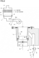
- the combustion apparatus represented in FIG. 1 is a heat source apparatus comprising: a totally aerated combustion burner 1; a combustion box 2 enclosing a combustion space of an air-fuel mixture to be ejected from a combustion surface 1a of the burner 1; and a heat exchanger 3 disposed inside the combustion box 2.
- the combustion gas generated by the combustion of the air-fuel mixture is exhausted outside, after having heated the heat exchanger 3, through an exhaust tube 4 that is connected to an end part of the combustion tube 2.
- the premixing apparatus A according to an embodiment of this invention, air is mixed with a fuel gas, and the resultant air-fuel mixture is supplied to the burner 1 through a fan 5.
- the premixing apparatus A is provided with: an air supply passage 6 on an upstream side of the fan 5; a gas supply passage 7 for supplying the fuel gas; and an air-fuel mixture supply passage 8 between the burner 1 on the downstream side of the fan 5.
- the downstream end of the gas supply passage 7 is connected to a gas suction part 61 which is disposed in the air supply passage 6.
- a venturi part 63 of a smaller diameter than the portion in which is disposed a butterfly valve 62 which will be described in detail hereinafter.
- the portion of the air supply passage 6, adjacent to the downstream side of the venture part 63, is enclosed by a tubular part 64 that is larger in diameter than the venturi part 63.
- the downstream end of the venturi part 63 is thus inserted, while leaving an annular clearance, into the upstream end of the tubular part 64, thereby constituting a gas suction part 61 by this clearance.
- the downstream end of the gas supply passage 7 is provided with a gas chamber 71 which is in communication with the gas suction part 61 in a manner to enclose the tubular part 64.
- the gas supply passage 7 has interposed therein, from the upstream side downward in sequence, a main valve 72, a zero governor 73 which adjusts the secondary gas pressure to atmospheric pressure, and a flow control valve 74.
- the amount of the fuel gas to be supplied through the gas suction part 61 varies with the differential pressure between the atmospheric pressure that is the secondary pressure and the negative pressure in the air supply passage 6. It is to be noted here that the negative pressure in the air supply passage 6 varies with the rotational speed of the fan 5. Therefore, the supply amount of the fuel gas varies in proportion to the rotational speed of the fan 5, i.e., in proportion to the supply amount of air. Further, the ratio of supply amount of the fuel gas to the supply amount of air varies with the opening degree of the flow control valve 74. By making the opening degree of the flow control valve 74 to a predetermined standard opening degree according to the kind of gas to be used, the excess air ratio of the air-fuel mixture will become an appropriate value (e.g., 1.3).
- the air-fuel mixture can be supplied to the burner 1 in an amount according to the required combustion amount at the appropriate value in the excess air ratio.
- the lower-limit rotational speed of the fan 5 cannot be set to a considerably lower value.
- the air corresponding to the required combustion amount can no longer be supplied.
- a butterfly valve 62 that can be switched, by a motor (not illustrated), between a closed posture as illustrated in solid lines in FIG. 1 and an open posture as illustrated in imaginary lines.
- the butterfly valve 62 is made into the closed posture in order to increase the flow resistance in the air supply passage 6. According to this arrangement, it is possible to supply air in an amount that corresponds to the predetermined required combustion amount below the required amount without making the rotational speed of the fan 5 below the lower-limit rotational speed.
- the butterfly valve 62 is made into the closed posture in order to make the flow resistance in the air supply passage 6 larger and, at the same time, the flow control valve 74 is throttled by an amount corresponding to the predetermined opening degree from the standard opening degree, thereby attaining a small-capacity state in which the flow resistance in a portion, on the downstream side of the zero governor 73, of the gas supply passage 7 is made larger.
- the air-fuel mixture can be supplied to the burner 1 in an amount that corresponds to a relatively small required combustion amount at the appropriate value in the excess air ratio.
- the butterfly valve 62 is made into an open posture in order to make the flow resistance in the air supply passage 6 smaller and, at the same time, the flow control valve 74 is opened up to the standard opening degree in order to attain a large-capacity state in which the flow resistance in a portion, on the downstream side of the zero governor 73, of the gas supply passage 7 is made small.
- the burner 1 can be supplied with the air-fuel mixture in an amount that corresponds to a relatively large required combustion amount at the appropriate value in the excess air ratio.
- a swing valve 81 that is capable of swinging from a closed posture (the posture illustrated in imaginary lines in FIG. 1 ) of being hung down with an upper end shaft 81a serving as a fulcrum to a bottom-up open side against a self-weight thereof.
- a closed posture the posture illustrated in imaginary lines in FIG. 1
- the swing valve 81 will be swung upward by the wind pressure from the fan 5 against its self-weight, thereby attaining a fully-opened state.
- the swing valve 81 comes to be swung gradually downward from the fully-opened state accompanied by the lowering of the rotational speed of the fan 5 and, as a result, the passage area of the air-fuel mixture supply passage 8 gradually decreases.
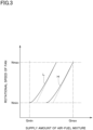
- the relationship between the rotational speed of the fan 5 and the supply amount of the air-fuel mixture is as illustrated by a characteristic line L in FIG. 3 in the small-capacity state, and is as illustrated by a characteristic line H in FIG. 3 in the large-capacity state.
- these characteristic curves L, H will become those in which the supply amounts of the air-fuel mixture are made smaller than those of the proportional lines illustrated in FIG. 3 by dotted lines.
- a large turndown ratio (maximum amount of combustion / minimum amount of combustion) that is the ratio between: the amount Qmax of supply of the air-fuel mixture at the time when the rotational speed of the fan 5 is made the upper limit rotational speed Nmax in the state of large capacity, i.e., the maximum amount of combustion by the burner 1; and the amount Qmin of supply of the air-fuel mixture at the time when the rotational speed of the fan 5 is made the lower limit rotational speed Nmin in the state of small capacity, i.e., the minimum amount of combustion by the burner 1.
- an excess air ratio detection means 9 for detecting the excess air ratio of the air-fuel mixture.
- a flame rod provided in a manner to face the combustion surface 1a of the burner 1 constitutes the excess air ratio detection means 9 so that the excess air ratio of the air-fuel mixture can be detected by flame current that flows through the flame rod.
- the flow control valve 74 is feed-back controlled so that the excess air ratio of the air-fuel mixture to be detected by the excess air ratio detection means 9 becomes constant, i.e., in order to keep the excess air ratio to a predetermined appropriate value. Specifically, when the excess air ratio in the air-fuel mixture is reduced by an increase in the calorific value of the fuel gas, the opening degree of the flow control valve 74 is reduced so that the ratio of the supply amount of the fuel gas relative to the supply amount of air is decreased so as to attain the appropriate value in the excess air ratio.
- the opening degree of the flow control valve 74 is increased so that the ratio of the supply amount of the fuel gas relative to the supply amount of air is increased so as to attain the appropriate value in the excess air ratio. According to this arrangement, even if the calorific value of the fuel gas fluctuates, the excess air ratio of the air-fuel mixture can be maintained at the appropriate value, thereby preventing the combustion failure from taking place.
- FIG. 2 The basic construction of the second combustion apparatus is not particularly different from that of the above-mentioned combustion apparatus.
- the members and parts that are the same as those of the first combustion apparatus have been assigned thereto the same reference marks.
- the difference of the second combustion apparatus from the first combustion apparatus is that a bypass passage 75 is provided in parallel with the flow control valve 74 in a portion, on a downstream side of the zero governor 73, of the gas supply passage 7, and that an on-off valve 76 is interposed in this bypass passage 75.
- the flow resistance in a portion, on the downstream side of the zero governor 73, of the gas supply passage 7 can be varied over a wide range: by the opening degree change in the state in which the fuel gas does not flow through the bypass passage 75 as a result of closing the on-off valve 76; and by the opening degree change of the flow control valve 74 in a state in which the fuel gas flows through the bypass passage 75 as a result of opening the on-off valve 76. Therefore, the deterioration in the controllability of the flow control valve 74 due to enlargement of the range in opening degree change can be avoided.
Landscapes
- Engineering & Computer Science (AREA)
- Chemical & Material Sciences (AREA)
- Combustion & Propulsion (AREA)
- Mechanical Engineering (AREA)
- General Engineering & Computer Science (AREA)
- Regulation And Control Of Combustion (AREA)
- Gas Burners (AREA)
Claims (1)
- Vormischvorrichtung (A) zum Mischen von Luft mit einem Brennstoffgas, um einen Brenner (1) durch ein Gebläse (5) mit einem Luft-Brennstoff-Gemisch zu versorgen,wobei ein Luftzufuhrdurchgang (6) der Vormischvorrichtung (A) auf einer vorgeordneten Seite des Gebläses (5) angeordnet ist, wobei ein Gaszufuhrdurchgang (7) der Vormischvorrichtung (A) darin dazwischengesetzt einen Nullregler (73) hat, um einen sekundären Gasdruck an einen atmosphärischen Druck anzupassen,wobei die Vormischvorrichtung (A) umfasst:den Luftzufuhrdurchgang (6);den Gaszufuhrdurchgang (7);ein Gasansaugteil (61), das in einem Abschnitt des Luftzufuhrdurchgangs (6) angeordnet ist, wobei ein nachgeordnetes Ende des Gaszufuhrdurchgangs (7) an das Gasansaugteil (61) angeschlossen ist;den Nullregler (73);eine Überschussluftverhältniserfassungsvorrichtung (9), um ein Überschussluftverhältnis des Luft-Brennstoff-Gemischs zu erfassen; undein Strömungssteuerungsventil (74), das in einem auf einer nachgeordneten Seite des Nullreglers (73) befindlichen Abschnitt des Gaszufuhrdurchgangs (7) dazwischengesetzt ist,wobei das Strömungssteuerungsventil (74) so gesteuert wird, dass das Überschussluftverhältnis des Luft-Brennstoff-Gemischs, das durch die Überschussluftverhältniserfassungsvorrichtung (9) erfasst wird, konstant wird, undwobei die Vormischvorrichtung (A) darüber hinaus eine Umgehung (75) mit einem darin dazwischengesetzten Ein/Aus-Ventil (76) umfasst, wobei die Umgehung (75) parallel mit dem Strömungssteuerungsventil (74) und in einem auf der nachgeordneten Seite des Nullreglers (73) befindlichen Abschnitt des Gaszufuhrdurchgangs (7) angeordnet ist.
Applications Claiming Priority (1)
| Application Number | Priority Date | Filing Date | Title |
|---|---|---|---|
| JP2019145279A JP2021025722A (ja) | 2019-08-07 | 2019-08-07 | 予混合装置 |
Publications (2)
| Publication Number | Publication Date |
|---|---|
| EP3772614A1 EP3772614A1 (de) | 2021-02-10 |
| EP3772614B1 true EP3772614B1 (de) | 2023-08-30 |
Family
ID=71607787
Family Applications (1)
| Application Number | Title | Priority Date | Filing Date |
|---|---|---|---|
| EP20185491.6A Active EP3772614B1 (de) | 2019-08-07 | 2020-07-13 | Vormischvorrichtung |
Country Status (3)
| Country | Link |
|---|---|
| US (1) | US20210041100A1 (de) |
| EP (1) | EP3772614B1 (de) |
| JP (1) | JP2021025722A (de) |
Families Citing this family (9)
| Publication number | Priority date | Publication date | Assignee | Title |
|---|---|---|---|---|
| CN111828977B (zh) * | 2020-07-16 | 2025-02-14 | 广东万和新电气股份有限公司 | 一种防倒流预混器及燃气热水器 |
| JP7538759B2 (ja) * | 2021-03-23 | 2024-08-22 | リンナイ株式会社 | 予混合装置 |
| JP7561075B2 (ja) * | 2021-03-26 | 2024-10-03 | リンナイ株式会社 | 予混合装置 |
| JP7697862B2 (ja) | 2021-10-12 | 2025-06-24 | リンナイ株式会社 | 予混合装置 |
| JP7697877B2 (ja) | 2021-12-07 | 2025-06-24 | リンナイ株式会社 | 送風装置 |
| JP7708653B2 (ja) | 2021-12-14 | 2025-07-15 | リンナイ株式会社 | 予混合装置 |
| JP7719008B2 (ja) | 2022-02-17 | 2025-08-05 | リンナイ株式会社 | 予混合装置 |
| JP2024002212A (ja) * | 2022-06-23 | 2024-01-11 | リンナイ株式会社 | 燃焼装置 |
| AU2023337772A1 (en) * | 2022-09-06 | 2024-12-19 | Rinnai Corporation | Premixing apparatus |
Citations (2)
| Publication number | Priority date | Publication date | Assignee | Title |
|---|---|---|---|---|
| US4585161A (en) * | 1984-04-27 | 1986-04-29 | Tokyo Gas Company Ltd. | Air fuel ratio control system for furnace |
| US20180187921A1 (en) * | 2015-07-09 | 2018-07-05 | Rinnai Corporation | Water heater |
Family Cites Families (7)
| Publication number | Priority date | Publication date | Assignee | Title |
|---|---|---|---|---|
| JPS56147974A (en) * | 1980-04-14 | 1981-11-17 | Youei Seisakusho:Kk | Proportional gas control apparatus |
| JP2644415B2 (ja) * | 1992-05-14 | 1997-08-25 | リンナイ株式会社 | 強制送風式燃焼装置 |
| JP2000146163A (ja) * | 1998-11-02 | 2000-05-26 | Harman Co Ltd | 燃焼装置 |
| JP2003148725A (ja) * | 2001-11-08 | 2003-05-21 | Paloma Ind Ltd | 強制燃焼装置 |
| JP6625925B2 (ja) * | 2016-04-06 | 2019-12-25 | リンナイ株式会社 | 予混合装置 |
| JP6831285B2 (ja) | 2017-04-19 | 2021-02-17 | リンナイ株式会社 | 予混合装置 |
| DE102017222437A1 (de) * | 2017-12-12 | 2019-06-13 | Robert Bosch Gmbh | Heizgerätkomponente und Verfahren zur Einstellung eines Brennstoffvolumenstroms |
-
2019
- 2019-08-07 JP JP2019145279A patent/JP2021025722A/ja active Pending
-
2020
- 2020-06-02 US US16/890,323 patent/US20210041100A1/en not_active Abandoned
- 2020-07-13 EP EP20185491.6A patent/EP3772614B1/de active Active
Patent Citations (2)
| Publication number | Priority date | Publication date | Assignee | Title |
|---|---|---|---|---|
| US4585161A (en) * | 1984-04-27 | 1986-04-29 | Tokyo Gas Company Ltd. | Air fuel ratio control system for furnace |
| US20180187921A1 (en) * | 2015-07-09 | 2018-07-05 | Rinnai Corporation | Water heater |
Also Published As
| Publication number | Publication date |
|---|---|
| EP3772614A1 (de) | 2021-02-10 |
| JP2021025722A (ja) | 2021-02-22 |
| US20210041100A1 (en) | 2021-02-11 |
Similar Documents
| Publication | Publication Date | Title |
|---|---|---|
| EP3772614B1 (de) | Vormischvorrichtung | |
| EP3228936B1 (de) | Verfahren zum betrieb eines gasbrennergeräts | |
| US7523762B2 (en) | Modulating gas valves and systems | |
| CN103443547A (zh) | 用于稳定燃气鼓风式燃烧器的运行行为的方法 | |
| US7789657B2 (en) | Pressure regulator with bleed orifice | |
| US12292188B2 (en) | Premixing apparatus | |
| JP7413145B2 (ja) | 燃焼装置 | |
| JP4713520B2 (ja) | 燃焼装置 | |
| CA2229129C (en) | A differential pressure modulated gas valve for single stage combustion control | |
| US20110203569A1 (en) | Boiler system stabilizing damper and flue control method | |
| KR102312889B1 (ko) | 가스버너장치 | |
| JP7697862B2 (ja) | 予混合装置 | |
| EP0614045A1 (de) | Verfahren und Vorrichtung zum Zuführen eines Luft-Gas-Gemisches in verschiedenen Durchflussmengen an einem Vormischbrenner | |
| KR930006168B1 (ko) | 연소기의 제어장치 | |
| CN109838808B (zh) | 热负荷调节装置及全预混燃气热水器 | |
| JP5200748B2 (ja) | 給湯装置 | |
| JP2021085639A (ja) | 給湯器 | |
| JP7719008B2 (ja) | 予混合装置 | |
| JP2025091881A (ja) | 燃焼装置 | |
| US12287091B2 (en) | Fan apparatus | |
| JP7638150B2 (ja) | 燃焼システム | |
| EP3617596B1 (de) | Verfahren zum betrieb eines gasbrennergeräts | |
| JPS6029516A (ja) | ガス燃焼制御装置 | |
| JP2669662B2 (ja) | 給湯機の制御装置 | |
| JPS649529B2 (de) |
Legal Events
| Date | Code | Title | Description |
|---|---|---|---|
| PUAI | Public reference made under article 153(3) epc to a published international application that has entered the european phase |
Free format text: ORIGINAL CODE: 0009012 |
|
| STAA | Information on the status of an ep patent application or granted ep patent |
Free format text: STATUS: THE APPLICATION HAS BEEN PUBLISHED |
|
| AK | Designated contracting states |
Kind code of ref document: A1 Designated state(s): AL AT BE BG CH CY CZ DE DK EE ES FI FR GB GR HR HU IE IS IT LI LT LU LV MC MK MT NL NO PL PT RO RS SE SI SK SM TR |
|
| AX | Request for extension of the european patent |
Extension state: BA ME |
|
| STAA | Information on the status of an ep patent application or granted ep patent |
Free format text: STATUS: REQUEST FOR EXAMINATION WAS MADE |
|
| 17P | Request for examination filed |
Effective date: 20210630 |
|
| RBV | Designated contracting states (corrected) |
Designated state(s): AL AT BE BG CH CY CZ DE DK EE ES FI FR GB GR HR HU IE IS IT LI LT LU LV MC MK MT NL NO PL PT RO RS SE SI SK SM TR |
|
| STAA | Information on the status of an ep patent application or granted ep patent |
Free format text: STATUS: EXAMINATION IS IN PROGRESS |
|
| 17Q | First examination report despatched |
Effective date: 20220509 |
|
| GRAP | Despatch of communication of intention to grant a patent |
Free format text: ORIGINAL CODE: EPIDOSNIGR1 |
|
| STAA | Information on the status of an ep patent application or granted ep patent |
Free format text: STATUS: GRANT OF PATENT IS INTENDED |
|
| INTG | Intention to grant announced |
Effective date: 20230413 |
|
| GRAS | Grant fee paid |
Free format text: ORIGINAL CODE: EPIDOSNIGR3 |
|
| GRAA | (expected) grant |
Free format text: ORIGINAL CODE: 0009210 |
|
| STAA | Information on the status of an ep patent application or granted ep patent |
Free format text: STATUS: THE PATENT HAS BEEN GRANTED |
|
| AK | Designated contracting states |
Kind code of ref document: B1 Designated state(s): AL AT BE BG CH CY CZ DE DK EE ES FI FR GB GR HR HU IE IS IT LI LT LU LV MC MK MT NL NO PL PT RO RS SE SI SK SM TR |
|
| REG | Reference to a national code |
Ref country code: GB Ref legal event code: FG4D |
|
| REG | Reference to a national code |
Ref country code: CH Ref legal event code: EP |
|
| REG | Reference to a national code |
Ref country code: DE Ref legal event code: R096 Ref document number: 602020016548 Country of ref document: DE |
|
| REG | Reference to a national code |
Ref country code: IE Ref legal event code: FG4D |
|
| REG | Reference to a national code |
Ref country code: LT Ref legal event code: MG9D |
|
| REG | Reference to a national code |
Ref country code: NL Ref legal event code: MP Effective date: 20230830 |
|
| REG | Reference to a national code |
Ref country code: AT Ref legal event code: MK05 Ref document number: 1605879 Country of ref document: AT Kind code of ref document: T Effective date: 20230830 |
|
| PG25 | Lapsed in a contracting state [announced via postgrant information from national office to epo] |
Ref country code: GR Free format text: LAPSE BECAUSE OF FAILURE TO SUBMIT A TRANSLATION OF THE DESCRIPTION OR TO PAY THE FEE WITHIN THE PRESCRIBED TIME-LIMIT Effective date: 20231201 |
|
| PG25 | Lapsed in a contracting state [announced via postgrant information from national office to epo] |
Ref country code: IS Free format text: LAPSE BECAUSE OF FAILURE TO SUBMIT A TRANSLATION OF THE DESCRIPTION OR TO PAY THE FEE WITHIN THE PRESCRIBED TIME-LIMIT Effective date: 20231230 |
|
| PG25 | Lapsed in a contracting state [announced via postgrant information from national office to epo] |
Ref country code: SE Free format text: LAPSE BECAUSE OF FAILURE TO SUBMIT A TRANSLATION OF THE DESCRIPTION OR TO PAY THE FEE WITHIN THE PRESCRIBED TIME-LIMIT Effective date: 20230830 Ref country code: RS Free format text: LAPSE BECAUSE OF FAILURE TO SUBMIT A TRANSLATION OF THE DESCRIPTION OR TO PAY THE FEE WITHIN THE PRESCRIBED TIME-LIMIT Effective date: 20230830 Ref country code: NO Free format text: LAPSE BECAUSE OF FAILURE TO SUBMIT A TRANSLATION OF THE DESCRIPTION OR TO PAY THE FEE WITHIN THE PRESCRIBED TIME-LIMIT Effective date: 20231130 Ref country code: LV Free format text: LAPSE BECAUSE OF FAILURE TO SUBMIT A TRANSLATION OF THE DESCRIPTION OR TO PAY THE FEE WITHIN THE PRESCRIBED TIME-LIMIT Effective date: 20230830 Ref country code: LT Free format text: LAPSE BECAUSE OF FAILURE TO SUBMIT A TRANSLATION OF THE DESCRIPTION OR TO PAY THE FEE WITHIN THE PRESCRIBED TIME-LIMIT Effective date: 20230830 Ref country code: IS Free format text: LAPSE BECAUSE OF FAILURE TO SUBMIT A TRANSLATION OF THE DESCRIPTION OR TO PAY THE FEE WITHIN THE PRESCRIBED TIME-LIMIT Effective date: 20231230 Ref country code: HR Free format text: LAPSE BECAUSE OF FAILURE TO SUBMIT A TRANSLATION OF THE DESCRIPTION OR TO PAY THE FEE WITHIN THE PRESCRIBED TIME-LIMIT Effective date: 20230830 Ref country code: GR Free format text: LAPSE BECAUSE OF FAILURE TO SUBMIT A TRANSLATION OF THE DESCRIPTION OR TO PAY THE FEE WITHIN THE PRESCRIBED TIME-LIMIT Effective date: 20231201 Ref country code: FI Free format text: LAPSE BECAUSE OF FAILURE TO SUBMIT A TRANSLATION OF THE DESCRIPTION OR TO PAY THE FEE WITHIN THE PRESCRIBED TIME-LIMIT Effective date: 20230830 Ref country code: AT Free format text: LAPSE BECAUSE OF FAILURE TO SUBMIT A TRANSLATION OF THE DESCRIPTION OR TO PAY THE FEE WITHIN THE PRESCRIBED TIME-LIMIT Effective date: 20230830 |
|
| PG25 | Lapsed in a contracting state [announced via postgrant information from national office to epo] |
Ref country code: PL Free format text: LAPSE BECAUSE OF FAILURE TO SUBMIT A TRANSLATION OF THE DESCRIPTION OR TO PAY THE FEE WITHIN THE PRESCRIBED TIME-LIMIT Effective date: 20230830 Ref country code: NL Free format text: LAPSE BECAUSE OF FAILURE TO SUBMIT A TRANSLATION OF THE DESCRIPTION OR TO PAY THE FEE WITHIN THE PRESCRIBED TIME-LIMIT Effective date: 20230830 |
|
| PG25 | Lapsed in a contracting state [announced via postgrant information from national office to epo] |
Ref country code: ES Free format text: LAPSE BECAUSE OF FAILURE TO SUBMIT A TRANSLATION OF THE DESCRIPTION OR TO PAY THE FEE WITHIN THE PRESCRIBED TIME-LIMIT Effective date: 20230830 |
|
| PG25 | Lapsed in a contracting state [announced via postgrant information from national office to epo] |
Ref country code: SM Free format text: LAPSE BECAUSE OF FAILURE TO SUBMIT A TRANSLATION OF THE DESCRIPTION OR TO PAY THE FEE WITHIN THE PRESCRIBED TIME-LIMIT Effective date: 20230830 Ref country code: RO Free format text: LAPSE BECAUSE OF FAILURE TO SUBMIT A TRANSLATION OF THE DESCRIPTION OR TO PAY THE FEE WITHIN THE PRESCRIBED TIME-LIMIT Effective date: 20230830 Ref country code: ES Free format text: LAPSE BECAUSE OF FAILURE TO SUBMIT A TRANSLATION OF THE DESCRIPTION OR TO PAY THE FEE WITHIN THE PRESCRIBED TIME-LIMIT Effective date: 20230830 Ref country code: EE Free format text: LAPSE BECAUSE OF FAILURE TO SUBMIT A TRANSLATION OF THE DESCRIPTION OR TO PAY THE FEE WITHIN THE PRESCRIBED TIME-LIMIT Effective date: 20230830 Ref country code: DK Free format text: LAPSE BECAUSE OF FAILURE TO SUBMIT A TRANSLATION OF THE DESCRIPTION OR TO PAY THE FEE WITHIN THE PRESCRIBED TIME-LIMIT Effective date: 20230830 Ref country code: CZ Free format text: LAPSE BECAUSE OF FAILURE TO SUBMIT A TRANSLATION OF THE DESCRIPTION OR TO PAY THE FEE WITHIN THE PRESCRIBED TIME-LIMIT Effective date: 20230830 Ref country code: SK Free format text: LAPSE BECAUSE OF FAILURE TO SUBMIT A TRANSLATION OF THE DESCRIPTION OR TO PAY THE FEE WITHIN THE PRESCRIBED TIME-LIMIT Effective date: 20230830 Ref country code: PT Free format text: LAPSE BECAUSE OF FAILURE TO SUBMIT A TRANSLATION OF THE DESCRIPTION OR TO PAY THE FEE WITHIN THE PRESCRIBED TIME-LIMIT Effective date: 20240102 |
|
| REG | Reference to a national code |
Ref country code: DE Ref legal event code: R097 Ref document number: 602020016548 Country of ref document: DE |
|
| PLBE | No opposition filed within time limit |
Free format text: ORIGINAL CODE: 0009261 |
|
| STAA | Information on the status of an ep patent application or granted ep patent |
Free format text: STATUS: NO OPPOSITION FILED WITHIN TIME LIMIT |
|
| PG25 | Lapsed in a contracting state [announced via postgrant information from national office to epo] |
Ref country code: SI Free format text: LAPSE BECAUSE OF FAILURE TO SUBMIT A TRANSLATION OF THE DESCRIPTION OR TO PAY THE FEE WITHIN THE PRESCRIBED TIME-LIMIT Effective date: 20230830 |
|
| 26N | No opposition filed |
Effective date: 20240603 |
|
| PG25 | Lapsed in a contracting state [announced via postgrant information from national office to epo] |
Ref country code: BG Free format text: LAPSE BECAUSE OF FAILURE TO SUBMIT A TRANSLATION OF THE DESCRIPTION OR TO PAY THE FEE WITHIN THE PRESCRIBED TIME-LIMIT Effective date: 20230830 |
|
| PG25 | Lapsed in a contracting state [announced via postgrant information from national office to epo] |
Ref country code: BG Free format text: LAPSE BECAUSE OF FAILURE TO SUBMIT A TRANSLATION OF THE DESCRIPTION OR TO PAY THE FEE WITHIN THE PRESCRIBED TIME-LIMIT Effective date: 20230830 |
|
| REG | Reference to a national code |
Ref country code: DE Ref legal event code: R119 Ref document number: 602020016548 Country of ref document: DE |
|
| PG25 | Lapsed in a contracting state [announced via postgrant information from national office to epo] |
Ref country code: MC Free format text: LAPSE BECAUSE OF FAILURE TO SUBMIT A TRANSLATION OF THE DESCRIPTION OR TO PAY THE FEE WITHIN THE PRESCRIBED TIME-LIMIT Effective date: 20230830 |
|
| REG | Reference to a national code |
Ref country code: CH Ref legal event code: PL |
|
| PG25 | Lapsed in a contracting state [announced via postgrant information from national office to epo] |
Ref country code: LU Free format text: LAPSE BECAUSE OF NON-PAYMENT OF DUE FEES Effective date: 20240713 |
|
| PG25 | Lapsed in a contracting state [announced via postgrant information from national office to epo] |
Ref country code: LU Free format text: LAPSE BECAUSE OF NON-PAYMENT OF DUE FEES Effective date: 20240713 |
|
| PG25 | Lapsed in a contracting state [announced via postgrant information from national office to epo] |
Ref country code: DE Free format text: LAPSE BECAUSE OF NON-PAYMENT OF DUE FEES Effective date: 20250201 |
|
| PG25 | Lapsed in a contracting state [announced via postgrant information from national office to epo] |
Ref country code: CH Free format text: LAPSE BECAUSE OF NON-PAYMENT OF DUE FEES Effective date: 20240731 Ref country code: BE Free format text: LAPSE BECAUSE OF NON-PAYMENT OF DUE FEES Effective date: 20240731 |
|
| PG25 | Lapsed in a contracting state [announced via postgrant information from national office to epo] |
Ref country code: FR Free format text: LAPSE BECAUSE OF NON-PAYMENT OF DUE FEES Effective date: 20240731 |
|
| REG | Reference to a national code |
Ref country code: BE Ref legal event code: MM Effective date: 20240731 |
|
| PG25 | Lapsed in a contracting state [announced via postgrant information from national office to epo] |
Ref country code: IE Free format text: LAPSE BECAUSE OF NON-PAYMENT OF DUE FEES Effective date: 20240713 |
|
| PGFP | Annual fee paid to national office [announced via postgrant information from national office to epo] |
Ref country code: IT Payment date: 20250724 Year of fee payment: 6 |
|
| PGFP | Annual fee paid to national office [announced via postgrant information from national office to epo] |
Ref country code: GB Payment date: 20250722 Year of fee payment: 6 |
|
| PG25 | Lapsed in a contracting state [announced via postgrant information from national office to epo] |
Ref country code: CY Free format text: LAPSE BECAUSE OF FAILURE TO SUBMIT A TRANSLATION OF THE DESCRIPTION OR TO PAY THE FEE WITHIN THE PRESCRIBED TIME-LIMIT; INVALID AB INITIO Effective date: 20200713 |
|
| PG25 | Lapsed in a contracting state [announced via postgrant information from national office to epo] |
Ref country code: HU Free format text: LAPSE BECAUSE OF FAILURE TO SUBMIT A TRANSLATION OF THE DESCRIPTION OR TO PAY THE FEE WITHIN THE PRESCRIBED TIME-LIMIT; INVALID AB INITIO Effective date: 20200713 |