EP3772592A1 - Radialgebläse für einen dunstabzug - Google Patents
Radialgebläse für einen dunstabzug Download PDFInfo
- Publication number
- EP3772592A1 EP3772592A1 EP20187187.8A EP20187187A EP3772592A1 EP 3772592 A1 EP3772592 A1 EP 3772592A1 EP 20187187 A EP20187187 A EP 20187187A EP 3772592 A1 EP3772592 A1 EP 3772592A1
- Authority
- EP
- European Patent Office
- Prior art keywords
- radial
- outlet
- axial
- impeller
- fan according
- Prior art date
- Legal status (The legal status is an assumption and is not a legal conclusion. Google has not performed a legal analysis and makes no representation as to the accuracy of the status listed.)
- Granted
Links
Images
Classifications
-
- F—MECHANICAL ENGINEERING; LIGHTING; HEATING; WEAPONS; BLASTING
- F04—POSITIVE - DISPLACEMENT MACHINES FOR LIQUIDS; PUMPS FOR LIQUIDS OR ELASTIC FLUIDS
- F04D—NON-POSITIVE-DISPLACEMENT PUMPS
- F04D29/00—Details, component parts, or accessories
- F04D29/26—Rotors specially for elastic fluids
- F04D29/28—Rotors specially for elastic fluids for centrifugal or helico-centrifugal pumps for radial-flow or helico-centrifugal pumps
- F04D29/281—Rotors specially for elastic fluids for centrifugal or helico-centrifugal pumps for radial-flow or helico-centrifugal pumps for fans or blowers
-
- F—MECHANICAL ENGINEERING; LIGHTING; HEATING; WEAPONS; BLASTING
- F04—POSITIVE - DISPLACEMENT MACHINES FOR LIQUIDS; PUMPS FOR LIQUIDS OR ELASTIC FLUIDS
- F04D—NON-POSITIVE-DISPLACEMENT PUMPS
- F04D17/00—Radial-flow pumps, e.g. centrifugal pumps; Helico-centrifugal pumps
- F04D17/08—Centrifugal pumps
- F04D17/16—Centrifugal pumps for displacing without appreciable compression
-
- F—MECHANICAL ENGINEERING; LIGHTING; HEATING; WEAPONS; BLASTING
- F04—POSITIVE - DISPLACEMENT MACHINES FOR LIQUIDS; PUMPS FOR LIQUIDS OR ELASTIC FLUIDS
- F04D—NON-POSITIVE-DISPLACEMENT PUMPS
- F04D25/00—Pumping installations or systems
- F04D25/02—Units comprising pumps and their driving means
- F04D25/06—Units comprising pumps and their driving means the pump being electrically driven
-
- F—MECHANICAL ENGINEERING; LIGHTING; HEATING; WEAPONS; BLASTING
- F04—POSITIVE - DISPLACEMENT MACHINES FOR LIQUIDS; PUMPS FOR LIQUIDS OR ELASTIC FLUIDS
- F04D—NON-POSITIVE-DISPLACEMENT PUMPS
- F04D29/00—Details, component parts, or accessories
- F04D29/40—Casings; Connections of working fluid
- F04D29/42—Casings; Connections of working fluid for radial or helico-centrifugal pumps
- F04D29/4206—Casings; Connections of working fluid for radial or helico-centrifugal pumps especially adapted for elastic fluid pumps
- F04D29/4226—Fan casings
-
- F—MECHANICAL ENGINEERING; LIGHTING; HEATING; WEAPONS; BLASTING
- F04—POSITIVE - DISPLACEMENT MACHINES FOR LIQUIDS; PUMPS FOR LIQUIDS OR ELASTIC FLUIDS
- F04D—NON-POSITIVE-DISPLACEMENT PUMPS
- F04D29/00—Details, component parts, or accessories
- F04D29/66—Combating cavitation, whirls, noise, vibration or the like; Balancing
- F04D29/661—Combating cavitation, whirls, noise, vibration or the like; Balancing especially adapted for elastic fluid pumps
- F04D29/663—Sound attenuation
Definitions
- the invention relates to a radial fan for an extractor hood with a spiral fan housing.
- drum fans and backward-curved centrifugal fans are mainly used for extractor hoods and extractor hoods.
- these have a comparatively large axial space requirement.
- the invention is therefore based on the object of an axially compact fan for use with an extractor hood or an extractor hood, which is aerodynamically improved in such a way that the noise development is minimized.
- a radial fan designed for an extractor which has a spiral fan housing with an axial suction opening and a radial exhaust opening and a radial impeller arranged in the fan housing with impeller blades arranged in a blade ring.
- the radial impeller has an axial intake assigned to the axial intake opening and a radial outlet at the radial end of the impeller blades.
- the suction in its axial plane defines a suction cross-sectional area A and the blow-out a circumferential surface area M, a ratio of the intake cross-sectional area to the outer surface being established that: 0.75 A / M 1.0, more preferably 0.8 A / M ⁇ 0.9.
- the special geometric selection and definition of the ratio of the intake cross-sectional area A of the intake and the circumferential surface area M of the exhaust means that the intake flow within the radial impeller from its intake, through the flow channels between the impeller blades to the exhaust, is hardly delayed and thus the acoustic Behavior improved significantly. Due to the special ratio, the velocity profile of the flow at the discharge of the radial impeller is very uniform. In addition, noise-generating separation of the flow in the blade channel between the individual impeller blades is prevented.
- the ratio according to the invention can also contribute to the interaction of the radial impeller and the spiral tongue of the fan housing in such a way it is improved that the rotating tones generated on the spiral tongue are reduced.
- the radial fan preferably has backwardly curved impeller blades, i.e. the impeller blades extend in an arcuate manner against the direction of rotation. Due to the special ratio of the suction cross-sectional area to the lateral surface, backward curved impeller blades can be used, although this is actually disadvantageous with regard to the generation of rotating tones.
- the radial fan is designed in such a way that the spiral fan housing has an outlet opening pointing in the circumferential direction with a maximum outlet opening cross-sectional area S, a ratio of an intake opening cross-sectional area Q of the intake opening of the fan housing to the outlet opening cross-sectional area S, which is defined as: 1.2 Q / S 1 1.7. More preferably 1.4 Q / S 1.5 applies.
- the special geometric adaptation favors the flow behavior and helps to reduce the generation of rotating tones.
- a diameter ratio of a maximum diameter AD of the intake of the radial impeller to a maximum outlet diameter DD at the discharge of the radial impeller is set, that is: 0.65 AD / DD 0.75, more preferably 0.68 ⁇ AD / DD ⁇ 0.72 applies. It has been found that the specially selected ratio contributes particularly advantageously to solving the problem.
- an axial outlet width AB at the outlet of the radial impeller is determined in relation to the maximum outlet diameter DD at the outlet of the radial impeller, that the following applies: 0.1 ⁇ AB / DD ⁇ 0.15, more preferably applies 0.12 ⁇ AB / DD ⁇ 0.13.
- the spiral-shaped fan housing has an axial height H and a mean rectangular dimension B / L of its outer contour, a ratio of the axial height H to the mean rectangular dimension B / L being established, that is, 0, 15 H / (B / L) 1/2 0.25, more preferably 0.17 H / (B / L) 1/2 0.2.
- the radial fan is preferably designed in such a way that the radial impeller has a cover disk which determines the intake and which overstretched the impeller blades at least in sections.
- the cover disk has an axial disk height DS and the suction opening of the fan housing has an axial cylinder section with an axial cylinder height DZ, a ratio of the difference between the axial disk height DS and the cylinder height DZ to a / the maximum outlet diameter DD am
- the discharge of the radial impeller is determined that the following applies: 0.05 (DS-DZ) / DD 0.07, more preferably 0.055 (DS-DZ) / DD 0.065.
- the outlet opening of the spiral fan housing preferably has a rectangular cross-section with, in particular, rounded corners.
- the radial fan is preferably characterized in that the spiral fan housing forms a pressure space which increases in the circumferential direction over more than 180 °, in particular more than 270 °.
- the pressure chamber preferably increases in the radial direction to form the spiral shape from the spiral tongue to the outlet opening.
- An enlargement of the pressure space in the axial direction can also be provided.
- the axial height of the spiral fan housing is constant.
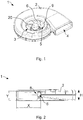
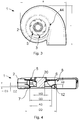
- FIGS 1-4 show an exemplary embodiment of the radial fan 1 designed for an extractor hood with the advantageous geometric relationships.
- the radial fan 1 comprises the spiral fan housing 2 with the axial suction opening 3 and the exhaust opening 4 formed at the end of the spiral.
- the fan housing 2 is formed from two axial parts.
- the motor 20 with a motor diameter MD in the intake area and the radial impeller 5 which can be driven by the motor 20 are positioned in the fan housing 2.
- the radial impeller 5 comprises a bottom disk 9 and a cover disk 12 with a large number of backward-curved impeller blades 6 running between them and arranged in a blade ring the radial outlet 8 at the radial end of the impeller blades 6.
- the suction opening 3 is formed on an axially retracted inlet nozzle of the fan housing 2.
- the ratio of the suction cross-sectional area A to the jacket area M is 0.85 in the exemplary embodiment shown.
- FIG. 3 determines the fan housing 2 in the axial plan view a maximum length L and a maximum width B.
- the axial maximum height H is in Figure 2 recognizable.
- the ratio H / (B / L) 1/2 of the axial height H to the mean rectangular dimension B / L is 0.18 in the embodiment shown.
- the spiral of the fan housing 2 increases exclusively in the radial direction starting from the spiral tongue 44 and over all four quadrants, ie over more than 270 °.
- This ratio Q / S has a value of 1.4 in the embodiment shown.
- the diameter ratio AD / DD of the maximum diameter AD of the intake 7 of the radial impeller 5 to the maximum outlet diameter DD at the outlet 8 of the radial impeller 5 is 0.7.
- the cover disk 12 of the radial impeller 5 has an axial disk height DS. With regard to its size, this is set in relation to the suction opening 3 of the fan housing 2, which defines the axial cylinder section with an axial cylinder height DZ.
Landscapes
- Engineering & Computer Science (AREA)
- Mechanical Engineering (AREA)
- General Engineering & Computer Science (AREA)
- Structures Of Non-Positive Displacement Pumps (AREA)
Abstract

Description
- Die Erfindung betrifft ein Radialgebläse für einen Dunstabzug mit einem spiralförmigen Gebläsegehäuse.
- Für Dunstabzüge und Dunstabzugshauben kommen im Stand der Technik hauptsächlich Trommelläufergebläse und rückwärtsgekrümmte Radialventilatoren zum Einsatz. Diese weisen jedoch einen vergleichsweise großen axialen Bauraumbedarf auf.
- Der Erfindung liegt deshalb die Aufgabe zugrunde, ein axial kompaktes Gebläse zum Einsatz bei einem Dunstabzug oder einer Dunstabzugshaube bereit zu stellen, das strömungstechnisch derart verbessert ist, dass die Geräuschentwicklung minimiert wird.
- Diese Aufgabe wird durch die Merkmalskombination gemäß Patentanspruch 1 gelöst.
- Erfindungsgemäß wird ein Radialgebläse ausgeführt für einen Dunstabzug vorgeschlagen, das ein spiralförmiges Gebläsegehäuse mit einer axialen Ansaugöffnung und einer radialen Ausblasöffnung sowie ein in dem Gebläsegehäuse angeordnetes Radiallaufrad mit in einem Schaufelkranz angeordneten Laufradschaufeln aufweist. Das Radiallaufrad weist einen der axialen Ansaugöffnung zugeordneten axialen Ansaug und einen radialen Ausblas am radialen Ende der Laufradschaufeln auf. Dabei bestimmen der Ansaug in seiner Axialebene eine Ansaugquerschnittsfläche A und der Ausblas eine umfängliche Mantelfläche M, wobei ein Verhältnis der Ansaugquerschnittsfläche zur Mantelfläche festgelegt ist, dass gilt: 0,75≤A/M≤1,0, weiter bevorzugt 0,8≤A/M≤0,9.
- Die geometrische spezielle Auswahl und Festlegung des Verhältnisses der Ansaugquerschnittsfläche A des Ansaug und umfänglichen Mantelfläche M des Ausblas führt dazu, dass die angesaugte Strömung innerhalb des Radiallaufrads von dessen Ansaug, durch die Strömungskanäle zwischen den Laufradschaufeln bis zum Ausblas kaum verzögert wird und sich somit das akustische Verhalten deutlich verbessert. Durch das spezielle Verhältnis ist das Geschwindigkeitsprofil der Strömung am Ausblas des Radiallaufrads sehr gleichmäßig. Zudem werden geräuscherzeugende Ablösungen der Strömung im Schaufelkanal zwischen den einzelnen Laufradschaufeln verhindert. Beim Einsatz in spiralförmigen Gebläsegehäusen kann das erfindungsgemäße Verhältnis zudem dazu beitragen, dass das Zusammenwirken von dem Radiallaufrad und der Spiralzunge des Gebläsegehäuses derart verbessert wird, dass die an der Spiralzunge erzeugten Drehtöne reduziert werden.
- Das Radialgebläse weist für eine verbesserte Effizienz vorzugsweise rückwärts gekrümmte Laufradschaufeln auf, d.h. die Laufradschaufeln erstrecken sich bogenförmig entgegen der Drehrichtung. Durch das spezielle Verhältnis der Ansaugquerschnittsfläche zur Mantelfläche können rückwärts gekrümmte Laufradschaufeln verwendet werden, obwohl dies eigentlich hinsichtlich der Erzeugung von Drehtönen nachteilig ist.
- In einer strömungstechnisch vorteilhaften Weiterbildung ist das Radialgebläse derart ausgebildet, dass das spiralförmige Gebläsegehäuse eine in Umfangsrichtung weisende Austrittsöffnung mit einer maximalen Austrittsöffnungsquerschnittsfläche S aufweist, wobei ein Verhältnis einer Ansaugöffnungsquerschnittsfläche Q der Ansaugöffnung des Gebläsegehäuses zur Austrittsöffnungsquerschnittsfläche S festgelegt ist, dass gilt: 1,2≤Q/S≤1,7. Weiter bevorzugt gilt 1,4≤Q/S≤1,5. Die spezielle geometrische Anpassung begünstigt das Strömungsverhalten und trägt dazu bei, die Erzeugung von Drehtönen zu reduzieren.
- Ein weiterer vorteilhafter Aspekt des Radialgebläses ist dadurch gekennzeichnet, dass ein Durchmesserverhältnis eines maximalen Durchmessers AD des Ansaug des Radiallaufrads zu einem maximalen Austrittsdurchmesser DD am Ausblas des Radiallaufrads festgelegt ist, dass gilt: 0,65≤AD/DD≤0,75, weiter bevorzugt gilt 0,68≤AD/DD≤0,72. Es wurde herausgefunden, dass das speziell ausgewählte Verhältnis besonders vorteilhaft zur Lösung der Aufgabe beiträgt.
- Zudem wird die Aufgabe noch besser durch ein Radialgebläse gelöst, bei dem eine axiale Austrittsbreite AB am Ausblas des Radiallaufrads im Verhältnis zu dem maximalen Austrittsdurchmesser DD am Ausblas des Radiallaufrads festgelegt ist, dass gilt: 0,1≤AB/DD≤0,15, weiter bevorzugt gilt 0, 12≤AB/DD≤0,13.
- Ferner ist in einer strömungstechnisch günstigen Ausführungsvariante des Radialgebläses vorgesehen, dass das spiralförmige Gebläsegehäuses eine axiale Höhe H und ein mittleres Rechtecksmaß B/L seiner Außenkontur aufweist, wobei ein Verhältnis der axialen Höhe H zum mittleren Rechtecksmaß B/L festgelegt ist, dass gilt 0,15≤H/(B/L)1/2≤0,25, weiter bevorzugt gilt 0,17≤H/(B/L)1/2≤0,2.
- Das Radialgebläse ist vorzugsweise derart ausgebildet, dass das Radiallaufrad eine den Ansaug bestimmende Deckscheibe aufweist, welche die Laufradschaufeln zumindest abschnittsweise überstreckt.
- Eine vorteilhafte Weiterbildung sieht vor, dass die Deckscheibe eine axiale Scheibenhöhe DS und die Ansaugöffnung des Gebläsegehäuses einen axialen Zylinderabschnitt mit einer axialen Zylinderhöhe DZ aufweist, wobei ein Verhältnis der Differenz aus der axialen Scheibenhöhe DS und der Zylinderhöhe DZ zu einem/dem maximalen Austrittsdurchmesser DD am Ausblas des Radiallaufrads festgelegt ist, dass gilt: 0,05≤(DS-DZ)/DD≤0,07, weiter bevorzugt 0,055≤(DS-DZ)/DD≤0,065.
- Die Austrittsöffnung des spiralförmigen Gebläsegehäuses weist vorzugsweise einen rechteckigen Querschnitt mit insbesondere abgerundeten Ecken auf.
- Zudem ist das Radialgebläse vorzugsweise dadurch gekennzeichnet, dass das spiralförmige Gebläsegehäuse einen sich in Umfangsrichtung über mehr als 180°, insbesondere mehr als 270° vergrößernden Druckraum bildet. Vorzugsweise vergrößert sich der Druckraum in Radialrichtung zur Bildung der Spiralform von der Spiralzunge bis zur Austrittsöffnung. Auch eine Vergrößerung des Druckraums in Axialrichtung kann vorgesehen werden. Vorzugsweise ist die axiale Höhe des spiralförmigen Gebläsegehäuses jedoch konstant.
- Andere vorteilhafte Weiterbildungen der Erfindung sind in den Unteransprüchen gekennzeichnet bzw. werden nachstehend zusammen mit der Beschreibung der bevorzugten Ausführung der Erfindung anhand der Figuren näher dargestellt. Es zeigen:
- Fig. 1
- eine perspektivische Ansicht eines Radialgebläses;
- Fig. 2
- das Radialgebläse aus
Figur 1 in der Seitenansicht; - Fig. 3
- das Radialgebläse aus
Figur 1 in der axialen Draufsicht; - Fig. 2
- das Radialgebläse aus
Figur 1 in einer Schnittansicht. - Die
Figuren 1-4 zeigen beispielhaft ein Ausführungsbeispiel des Radialgebläses 1 ausgeführt für einen Dunstabzug mit den vorteilhaften geometrischen Verhältnissen. - Das Radialgebläse 1 umfasst das spiralförmige Gebläsegehäuse 2 mit der axialen Ansaugöffnung 3 und der am Ende der Spirale ausgebildeten Ausblasöffnung 4. Das Gebläsegehäuse 2 ist aus zwei Axialteilen gebildet. Im Gebläsegehäuse 2 ist der Motor 20 mit einem Motordurchmesser MD im Ansaugbereich und das über den Motor 20 antreibbare Radiallaufrad 5 positioniert. Das Radiallaufrad 5 umfasst eine Bodenscheibe 9 und eine Deckscheibe 12 mit einer Vielzahl von dazwischen verlaufenden, in einem Schaufelkranz angeordneten rückwärts gekrümmten Laufradschaufeln 6. Auf der der Ansaugöffnung 3 zugeordneten axialen Seite bestimmt das Radiallaufrad 5 den axialen Ansaug 7 und am radialen Außenrand bzw. Außenmantel den radialen Ausblas 8 am radialen Ende der Laufradschaufeln 6. Die Ansaugöffnung 3 ist an einer axial eingezogenen Einlaufdüse des Gebläsegehäuses 2 ausgebildet.
- Der Ansaug 7 des Radiallaufrads 5 bestimmt in der Axialebene am Eintritt in das Radiallaufrad 5 seine Ansaugquerschnittsfläche A, welche in der gezeigten Ausführung durch den Ansaugdurchmesser AD bestimmt wird als A=π·(AD/2)2. Der Ausblas 8 bestimmt die umfängliche Mantelfläche M als Zylindermantelfläche, welche sich über den maximalen Austrittsdurchmesser DD am Ausblas 8 und die axiale Austrittsbreite AB des Radiallaufrads 5 berechnet als M=AB·π·DD. Das Verhältnis der Ansaugquerschnittsfläche A zur Mantelfläche M ist im gezeigten Ausführungsbeispiel 0,85.
- Bezugnehmen auf
Figur 3 bestimmt das Gebläsegehäuse 2 in der axialen Draufsicht eine maximale Länge L und eine maximale Breite B. Die axiale maximale Höhe H ist inFigur 2 erkennbar. Das Verhältnis H/(B/L)1/2 der axialen Höhe H zum mittleren Rechtecksmaß B/L ist in der gezeigten Ausführung 0,18. Die Spirale des Gebläsegehäuses 2 vergrößert sich ausschließlich in radialer Richtung ausgehend von der Spiralzunge 44 und über alle vier Quadranten, d.h. über mehr als 270°. - Weiterhin bezugnehmend auf
Figur 2 ist die in Umfangsrichtung weisende Austrittsöffnung 4 des spiralförmigen Gebläsegehäuses 2 von der Austrittseite gezeigt und weist eine Breite X und eine Höhe Y auf, welche die maximale Austrittsöffnungsquerschnittsfläche S=X·Y abzüglich der gerundeten Ecken bestimmen. Die Austrittsöffnungsquerschnittsfläche S ist ins Verhältnis zur Ansaugöffnungsquerschnittsfläche Q der Ansaugöffnung 3 des Gebläsegehäuses 2 gesetzt, wobei die Ansaugöffnungsquerschnittsfläche Q bestimmt wird durch Q= π·(QD/2)2, wie in denFiguren 1 und4 gezeigt. Dieses Verhältnis Q/S liegt in der gezeigten Ausführung bei einem Wert von 1,4. Das Durchmesserverhältnis AD/DD des maximalen Durchmessers AD des Ansaug 7 des Radiallaufrads 5 zu dem maximalen Austrittsdurchmesser DD am Ausblas 8 des Radiallaufrads 5 liegt bei einem Wert von 0,7. - Ferner ist die axiale Austrittsbreite AB am Ausblas 8 des Radiallaufrads 5 im Verhältnis zu dem maximalen Austrittsdurchmesser DD am Ausblas 8 des Radiallaufrads 5 auf den Wert AB/DD=0,12 festgelegt.
- Bezugnehmend auf
Figur 4 ist gezeigt, dass die Deckscheibe 12 des Radiallaufrads 5 eine axiale Scheibenhöhe DS aufweist. Diese ist bezüglich ihrer Größe ins Verhältnis zur Ansaugöffnung 3 des Gebläsegehäuses 2 gesetzt, die den axialen Zylinderabschnitt mit einer axialen Zylinderhöhe DZ bestimmt. Dabei ist das Verhältnis der Differenz aus axialen Scheibenhöhe DS und der Zylinderhöhe DZ zu dem maximalen Austrittsdurchmesser DD am Ausblas 8 des Radiallaufrads 5 so festgelegt, dass (DS-DZ)/DD=0,6. - Das Ausführungsbeispiel gemäß der
Figuren 1 - 4 ist bezüglich der genannten Verhältnisse im Rahmen der vorstehend beschriebenen und in den nachfolgenden Ansprüche definierten Bereiche anpassbar.
Claims (15)
- Radialgebläse (1) für einen Dunstabzug mit einem spiralförmigen Gebläsegehäuse (2) mit einer axialen Ansaugöffnung (3) und einer Ausblasöffnung (4), einem in dem Gebläsegehäuse (2) angeordneten Radiallaufrad (5) mit in einem Schaufelkranz angeordneten Laufradschaufeln (6), wobei das Radiallaufrad (5) einen der axialen Ansaugöffnung (3) zugeordneten axialen Ansaug (7) und einen radialen Ausblas (8) am radialen Ende der Laufradschaufeln (6) aufweist, wobei der Ansaug (7) in seiner Axialebene eine Ansaugquerschnittsfläche A und der Ausblas (8) eine umfängliche Mantelfläche M bestimmen und ein Verhältnis der Ansaugquerschnittsfläche A zur Mantelfläche M festgelegt ist, dass gilt: 0,75≤A/M≤1,0.
- Radialgebläse nach Anspruch 1, dadurch gekennzeichnet, dass gilt 0,8≤A/M≤0,9.
- Radialgebläse nach Anspruch 1 oder 2, dadurch gekennzeichnet, dass die Laufradschaufeln (6) rückwärts gekrümmt ausgeführt sind.
- Radialgebläse nach Anspruch 1 oder 2, dadurch gekennzeichnet, dass die in Umfangsrichtung weisende Austrittsöffnung (4) des spiralförmigen Gebläsegehäuses (2) eine maximale Austrittsöffnungsquerschnittsfläche S aufweist, wobei ein Verhältnis einer Ansaugöffnungsquerschnittsfläche Q der Ansaugöffnung (3) des Gebläsegehäuses (2) zur Austrittsöffnungsquerschnittsfläche S festgelegt ist, dass gilt: 1,2≤Q/S≤1,7.
- Radialgebläse nach Anspruch 4, dadurch gekennzeichnet, dass gilt 1,4≤Q/S≤1,5.
- Radialgebläse nach einem der vorigen Ansprüche, dadurch gekennzeichnet, dass ein Durchmesserverhältnis eines maximalen Durchmessers AD des Ansaug (7) des Radiallaufrads (5) zu einem maximalen Austrittsdurchmesser DD am Ausblas (8) des Radiallaufrads (5) festgelegt ist, dass gilt: 0,65≤AD/DD≤0,75.
- Radialgebläse nach Anspruch 6, dadurch gekennzeichnet, dass gilt 0,68≤AD/DD≤0,72.
- Radialgebläse nach einem der vorigen Ansprüche, dadurch gekennzeichnet, dass eine axiale Austrittsbreite AB am Ausblas (8) des Radiallaufrads (5) im Verhältnis zu einem/dem maximalen Austrittsdurchmesser DD am Ausblas (8) des Radiallaufrads (5) festgelegt ist, dass gilt: 0,1≤AB/DD≤0,15
- Radialgebläse nach Anspruch 8, dadurch gekennzeichnet, dass gilt 0, 12≤AB/DD≤0, 13.
- Radialgebläse nach einem der vorigen Ansprüche, dadurch gekennzeichnet, dass das spiralförmige Gebläsegehäuses (2) eine axiale Höhe H und ein mittleres Rechtecksmaß B/L seiner Außenkontur aufweist, wobei ein Verhältnis der axialen Höhe H zum mittleren Rechtecksmaß B/L festgelegt ist, dass gilt 0,15≤H/(B/L)1/2≤0,25.
- Radialgebläse nach Anspruch 10, dadurch gekennzeichnet, dass gilt 0,17≤H/(B/L)1/2≤0,2.
- Radialgebläse nach einem der vorigen Ansprüche, dadurch gekennzeichnet, dass das Radiallaufrad (5) eine den Ansaug (7) bestimmende Deckscheibe aufweist, welche die Laufradschaufeln (6) zumindest abschnittsweise überstreckt.
- Radialgebläse nach dem vorigen Anspruch, dadurch gekennzeichnet, dass die Deckscheibe eine axiale Scheibenhöhe DS und die Ansaugöffnung (3) des Gebläsegehäuses (2) einen axialen Zylinderabschnitt mit einer axialen Zylinderhöhe DZ aufweist, wobei ein Verhältnis der Differenz aus axialen Scheibenhöhe DS und der Zylinderhöhe DZ zu einem/dem maximalen Austrittsdurchmesser DD am Ausblas (8) des Radiallaufrads (5) festgelegt ist, dass gilt: 0,05≤(DS-DZ)/DD≤0,07, insbesondere 0,055:5(DS-DZ)/DD:50,065.
- Radialgebläse nach einem der vorigen Ansprüche, dadurch gekennzeichnet, dass die Austrittsöffnung des spiralförmigen Gebläsegehäuses (2) einen rechteckigen Querschnitt mit insbesondere abgerundeten Ecken aufweist.
- Radialgebläse nach einem der vorigen Ansprüche, dadurch gekennzeichnet, dass das spiralförmige Gebläsegehäuses (2) einen sich in Umfangsrichtung über mehr als 180°, insbesondere mehr als 270° vergrößernden Druckraum bildet.
Applications Claiming Priority (1)
| Application Number | Priority Date | Filing Date | Title |
|---|---|---|---|
| DE102019121448.3A DE102019121448A1 (de) | 2019-08-08 | 2019-08-08 | Radialgebläse für einen Dunstabzug |
Publications (2)
| Publication Number | Publication Date |
|---|---|
| EP3772592A1 true EP3772592A1 (de) | 2021-02-10 |
| EP3772592B1 EP3772592B1 (de) | 2026-04-22 |
Family
ID=71741687
Family Applications (1)
| Application Number | Title | Priority Date | Filing Date |
|---|---|---|---|
| EP20187187.8A Active EP3772592B1 (de) | 2019-08-08 | 2020-07-22 | Radialgebläse für einen dunstabzug |
Country Status (3)
| Country | Link |
|---|---|
| EP (1) | EP3772592B1 (de) |
| CN (1) | CN211474516U (de) |
| DE (1) | DE102019121448A1 (de) |
Families Citing this family (1)
| Publication number | Priority date | Publication date | Assignee | Title |
|---|---|---|---|---|
| DE102020216155A1 (de) * | 2020-12-17 | 2022-06-23 | Ziehl-Abegg Se | Ventilator und Spiralgehäuse für einen Ventilator |
Citations (3)
| Publication number | Priority date | Publication date | Assignee | Title |
|---|---|---|---|---|
| GB2063365A (en) * | 1979-10-08 | 1981-06-03 | Punker Gmbh | Radial Flow Fans |
| US4526506A (en) * | 1982-12-29 | 1985-07-02 | Wilhelm Gebhardt Gmbh | Radial fan with backwardly curving blades |
| US20150037156A1 (en) * | 2013-07-31 | 2015-02-05 | Samsung Electro-Mechanics Co., Ltd. | Impeller for electric blower |
Family Cites Families (2)
| Publication number | Priority date | Publication date | Assignee | Title |
|---|---|---|---|---|
| JP5143173B2 (ja) * | 2010-03-29 | 2013-02-13 | 三菱電機株式会社 | ターボファン及びこれを装備した空気調和機の室内機 |
| UA114769C2 (uk) * | 2016-06-21 | 2017-07-25 | Андрій Іванович Панфілов | Робоче колесо відцентрового вентилятора |
-
2019
- 2019-08-08 DE DE102019121448.3A patent/DE102019121448A1/de active Pending
- 2019-10-22 CN CN201921773575.1U patent/CN211474516U/zh active Active
-
2020
- 2020-07-22 EP EP20187187.8A patent/EP3772592B1/de active Active
Patent Citations (3)
| Publication number | Priority date | Publication date | Assignee | Title |
|---|---|---|---|---|
| GB2063365A (en) * | 1979-10-08 | 1981-06-03 | Punker Gmbh | Radial Flow Fans |
| US4526506A (en) * | 1982-12-29 | 1985-07-02 | Wilhelm Gebhardt Gmbh | Radial fan with backwardly curving blades |
| US20150037156A1 (en) * | 2013-07-31 | 2015-02-05 | Samsung Electro-Mechanics Co., Ltd. | Impeller for electric blower |
Also Published As
| Publication number | Publication date |
|---|---|
| EP3772592B1 (de) | 2026-04-22 |
| CN211474516U (zh) | 2020-09-11 |
| DE102019121448A1 (de) | 2021-02-11 |
Similar Documents
| Publication | Publication Date | Title |
|---|---|---|
| DE69209434T2 (de) | Kreiselverdichter | |
| DE102010046870A1 (de) | Seitenkanalgebläse, insbesondere Sekundärluftgebläse für eine Verbrennungskraftmaschine | |
| EP3404269B1 (de) | Gebläseanordnung mit strömungsteilungsdüse | |
| DE2421237C2 (de) | Eintauchpumpe | |
| EP3224481A1 (de) | Kreiselpumpe mit axialasschüttendem radiallaufrad | |
| DE60035842T2 (de) | Vakuumpumpen | |
| EP3916239A1 (de) | Gebläserad mit dreidimensional gekrümmten laufradschaufeln | |
| WO2017013021A1 (de) | Seitenkanal-maschine (verdichter, vakuumpumpe oder gebläse) mit einem entnahmekanal im abstreifer | |
| DE2908800A1 (de) | Mehrstufiger turbokompressor mit schaufelraedern fuer diagonalstroemung | |
| EP3571416B1 (de) | Gedecktes radialgebläserad mit einer periodisch und asymmetrisch geformten scheibe | |
| DE202018106504U1 (de) | Kompakter Diagonalventilator mit Nachleiteinrichtung | |
| EP3772592A1 (de) | Radialgebläse für einen dunstabzug | |
| DE10307887A1 (de) | Kreiselpumpe | |
| EP3088743B1 (de) | Seitenkanal-vakuumpumpstufe mit einem unterbrecher, der auf der saugseite abgeschrägt ist | |
| DE202019104368U1 (de) | Radialgebläse für einen Dunstabzug | |
| WO2007022648A1 (de) | Kreiselverdichter | |
| DE102010005517A1 (de) | Dispergierpumpe | |
| DE202017105384U1 (de) | Radialgebläserad mit asymmetrischer Scheibe | |
| DE19736678A1 (de) | Mehrstufige Seitenkanalpumpe | |
| DE102018132978A1 (de) | Turboverdichter mit angepasster Meridiankontur der Schaufeln und Verdichterwand | |
| EP3486494B1 (de) | Radialgebläsegehäuse und radialgebläse | |
| CH650563A5 (en) | Diffuser in a centrifugal driven machine | |
| DE10249244B4 (de) | Laufrad für eine Seitenkanalmaschine | |
| WO2020120506A1 (de) | Ventilationseinheit | |
| DE102015113985A1 (de) | Zentrifugalpumpe |
Legal Events
| Date | Code | Title | Description |
|---|---|---|---|
| PUAI | Public reference made under article 153(3) epc to a published international application that has entered the european phase |
Free format text: ORIGINAL CODE: 0009012 |
|
| STAA | Information on the status of an ep patent application or granted ep patent |
Free format text: STATUS: THE APPLICATION HAS BEEN PUBLISHED |
|
| AK | Designated contracting states |
Kind code of ref document: A1 Designated state(s): AL AT BE BG CH CY CZ DE DK EE ES FI FR GB GR HR HU IE IS IT LI LT LU LV MC MK MT NL NO PL PT RO RS SE SI SK SM TR |
|
| AX | Request for extension of the european patent |
Extension state: BA ME |
|
| STAA | Information on the status of an ep patent application or granted ep patent |
Free format text: STATUS: REQUEST FOR EXAMINATION WAS MADE |
|
| 17P | Request for examination filed |
Effective date: 20210721 |
|
| RBV | Designated contracting states (corrected) |
Designated state(s): AL AT BE BG CH CY CZ DE DK EE ES FI FR GB GR HR HU IE IS IT LI LT LU LV MC MK MT NL NO PL PT RO RS SE SI SK SM TR |
|
| STAA | Information on the status of an ep patent application or granted ep patent |
Free format text: STATUS: EXAMINATION IS IN PROGRESS |
|
| 17Q | First examination report despatched |
Effective date: 20221102 |
|
| GRAP | Despatch of communication of intention to grant a patent |
Free format text: ORIGINAL CODE: EPIDOSNIGR1 |
|
| STAA | Information on the status of an ep patent application or granted ep patent |
Free format text: STATUS: GRANT OF PATENT IS INTENDED |
|
| INTG | Intention to grant announced |
Effective date: 20260115 |
|
| GRAS | Grant fee paid |
Free format text: ORIGINAL CODE: EPIDOSNIGR3 |
|
| GRAA | (expected) grant |
Free format text: ORIGINAL CODE: 0009210 |
|
| STAA | Information on the status of an ep patent application or granted ep patent |
Free format text: STATUS: THE PATENT HAS BEEN GRANTED |
|
| AK | Designated contracting states |
Kind code of ref document: B1 Designated state(s): AL AT BE BG CH CY CZ DE DK EE ES FI FR GB GR HR HU IE IS IT LI LT LU LV MC MK MT NL NO PL PT RO RS SE SI SK SM TR |
|
| REG | Reference to a national code |
Ref country code: CH Ref legal event code: F10 Free format text: ST27 STATUS EVENT CODE: U-0-0-F10-F00 (AS PROVIDED BY THE NATIONAL OFFICE) Effective date: 20260422 Ref country code: GB Ref legal event code: FG4D Free format text: NOT ENGLISH |