EP3772052B1 - Anzeigevorrichtung - Google Patents
Anzeigevorrichtung Download PDFInfo
- Publication number
- EP3772052B1 EP3772052B1 EP20188613.2A EP20188613A EP3772052B1 EP 3772052 B1 EP3772052 B1 EP 3772052B1 EP 20188613 A EP20188613 A EP 20188613A EP 3772052 B1 EP3772052 B1 EP 3772052B1
- Authority
- EP
- European Patent Office
- Prior art keywords
- adjustment element
- display panel
- height adjustment
- display apparatus
- mount
- Prior art date
- Legal status (The legal status is an assumption and is not a legal conclusion. Google has not performed a legal analysis and makes no representation as to the accuracy of the status listed.)
- Active
Links
Images






Classifications
-
- G—PHYSICS
- G02—OPTICS
- G02F—OPTICAL DEVICES OR ARRANGEMENTS FOR THE CONTROL OF LIGHT BY MODIFICATION OF THE OPTICAL PROPERTIES OF THE MEDIA OF THE ELEMENTS INVOLVED THEREIN; NON-LINEAR OPTICS; FREQUENCY-CHANGING OF LIGHT; OPTICAL LOGIC ELEMENTS; OPTICAL ANALOGUE/DIGITAL CONVERTERS
- G02F1/00—Devices or arrangements for the control of the intensity, colour, phase, polarisation or direction of light arriving from an independent light source, e.g. switching, gating or modulating; Non-linear optics
- G02F1/01—Devices or arrangements for the control of the intensity, colour, phase, polarisation or direction of light arriving from an independent light source, e.g. switching, gating or modulating; Non-linear optics for the control of the intensity, phase, polarisation or colour
- G02F1/13—Devices or arrangements for the control of the intensity, colour, phase, polarisation or direction of light arriving from an independent light source, e.g. switching, gating or modulating; Non-linear optics for the control of the intensity, phase, polarisation or colour based on liquid crystals, e.g. single liquid crystal display cells
- G02F1/133—Constructional arrangements; Operation of liquid crystal cells; Circuit arrangements
- G02F1/1333—Constructional arrangements; Manufacturing methods
- G02F1/133308—Support structures for LCD panels, e.g. frames or bezels
-
- F—MECHANICAL ENGINEERING; LIGHTING; HEATING; WEAPONS; BLASTING
- F16—ENGINEERING ELEMENTS AND UNITS; GENERAL MEASURES FOR PRODUCING AND MAINTAINING EFFECTIVE FUNCTIONING OF MACHINES OR INSTALLATIONS; THERMAL INSULATION IN GENERAL
- F16M—FRAMES, CASINGS OR BEDS OF ENGINES, MACHINES OR APPARATUS, NOT SPECIFIC TO ENGINES, MACHINES OR APPARATUS PROVIDED FOR ELSEWHERE; STANDS; SUPPORTS
- F16M11/00—Stands or trestles as supports for apparatus or articles placed thereon ; Stands for scientific apparatus such as gravitational force meters
- F16M11/02—Heads
- F16M11/04—Means for attachment of apparatus; Means allowing adjustment of the apparatus relatively to the stand
- F16M11/043—Allowing translations
- F16M11/046—Allowing translations adapted to upward-downward translation movement
-
- G—PHYSICS
- G09—EDUCATION; CRYPTOGRAPHY; DISPLAY; ADVERTISING; SEALS
- G09F—DISPLAYING; ADVERTISING; SIGNS; LABELS OR NAME-PLATES; SEALS
- G09F9/00—Indicating arrangements for variable information in which the information is built-up on a support by selection or combination of individual elements
- G09F9/30—Indicating arrangements for variable information in which the information is built-up on a support by selection or combination of individual elements in which the desired character or characters are formed by combining individual elements
- G09F9/302—Indicating arrangements for variable information in which the information is built-up on a support by selection or combination of individual elements in which the desired character or characters are formed by combining individual elements characterised by the form or geometrical disposition of the individual elements
- G09F9/3026—Video wall, i.e. stackable semiconductor matrix display modules
-
- F—MECHANICAL ENGINEERING; LIGHTING; HEATING; WEAPONS; BLASTING
- F16—ENGINEERING ELEMENTS AND UNITS; GENERAL MEASURES FOR PRODUCING AND MAINTAINING EFFECTIVE FUNCTIONING OF MACHINES OR INSTALLATIONS; THERMAL INSULATION IN GENERAL
- F16M—FRAMES, CASINGS OR BEDS OF ENGINES, MACHINES OR APPARATUS, NOT SPECIFIC TO ENGINES, MACHINES OR APPARATUS PROVIDED FOR ELSEWHERE; STANDS; SUPPORTS
- F16M11/00—Stands or trestles as supports for apparatus or articles placed thereon ; Stands for scientific apparatus such as gravitational force meters
- F16M11/02—Heads
- F16M11/04—Means for attachment of apparatus; Means allowing adjustment of the apparatus relatively to the stand
- F16M11/043—Allowing translations
-
- G—PHYSICS
- G02—OPTICS
- G02F—OPTICAL DEVICES OR ARRANGEMENTS FOR THE CONTROL OF LIGHT BY MODIFICATION OF THE OPTICAL PROPERTIES OF THE MEDIA OF THE ELEMENTS INVOLVED THEREIN; NON-LINEAR OPTICS; FREQUENCY-CHANGING OF LIGHT; OPTICAL LOGIC ELEMENTS; OPTICAL ANALOGUE/DIGITAL CONVERTERS
- G02F1/00—Devices or arrangements for the control of the intensity, colour, phase, polarisation or direction of light arriving from an independent light source, e.g. switching, gating or modulating; Non-linear optics
- G02F1/01—Devices or arrangements for the control of the intensity, colour, phase, polarisation or direction of light arriving from an independent light source, e.g. switching, gating or modulating; Non-linear optics for the control of the intensity, phase, polarisation or colour
- G02F1/13—Devices or arrangements for the control of the intensity, colour, phase, polarisation or direction of light arriving from an independent light source, e.g. switching, gating or modulating; Non-linear optics for the control of the intensity, phase, polarisation or colour based on liquid crystals, e.g. single liquid crystal display cells
- G02F1/133—Constructional arrangements; Operation of liquid crystal cells; Circuit arrangements
- G02F1/1333—Constructional arrangements; Manufacturing methods
- G02F1/133308—Support structures for LCD panels, e.g. frames or bezels
- G02F1/133314—Back frames
-
- G—PHYSICS
- G02—OPTICS
- G02F—OPTICAL DEVICES OR ARRANGEMENTS FOR THE CONTROL OF LIGHT BY MODIFICATION OF THE OPTICAL PROPERTIES OF THE MEDIA OF THE ELEMENTS INVOLVED THEREIN; NON-LINEAR OPTICS; FREQUENCY-CHANGING OF LIGHT; OPTICAL LOGIC ELEMENTS; OPTICAL ANALOGUE/DIGITAL CONVERTERS
- G02F1/00—Devices or arrangements for the control of the intensity, colour, phase, polarisation or direction of light arriving from an independent light source, e.g. switching, gating or modulating; Non-linear optics
- G02F1/01—Devices or arrangements for the control of the intensity, colour, phase, polarisation or direction of light arriving from an independent light source, e.g. switching, gating or modulating; Non-linear optics for the control of the intensity, phase, polarisation or colour
- G02F1/13—Devices or arrangements for the control of the intensity, colour, phase, polarisation or direction of light arriving from an independent light source, e.g. switching, gating or modulating; Non-linear optics for the control of the intensity, phase, polarisation or colour based on liquid crystals, e.g. single liquid crystal display cells
- G02F1/133—Constructional arrangements; Operation of liquid crystal cells; Circuit arrangements
- G02F1/1333—Constructional arrangements; Manufacturing methods
- G02F1/133308—Support structures for LCD panels, e.g. frames or bezels
- G02F1/133325—Assembling processes
-
- G—PHYSICS
- G06—COMPUTING OR CALCULATING; COUNTING
- G06F—ELECTRIC DIGITAL DATA PROCESSING
- G06F1/00—Details not covered by groups G06F3/00 - G06F13/00 and G06F21/00
- G06F1/16—Constructional details or arrangements
- G06F1/1601—Constructional details related to the housing of computer displays, e.g. of CRT monitors, of flat displays
- G06F1/1607—Arrangements to support accessories mechanically attached to the display housing
-
- G—PHYSICS
- G09—EDUCATION; CRYPTOGRAPHY; DISPLAY; ADVERTISING; SEALS
- G09F—DISPLAYING; ADVERTISING; SIGNS; LABELS OR NAME-PLATES; SEALS
- G09F9/00—Indicating arrangements for variable information in which the information is built-up on a support by selection or combination of individual elements
- G09F9/30—Indicating arrangements for variable information in which the information is built-up on a support by selection or combination of individual elements in which the desired character or characters are formed by combining individual elements
- G09F9/33—Indicating arrangements for variable information in which the information is built-up on a support by selection or combination of individual elements in which the desired character or characters are formed by combining individual elements being semiconductor devices, e.g. diodes
- G09F9/335—Indicating arrangements for variable information in which the information is built-up on a support by selection or combination of individual elements in which the desired character or characters are formed by combining individual elements being semiconductor devices, e.g. diodes being organic light emitting diodes [OLED]
-
- F—MECHANICAL ENGINEERING; LIGHTING; HEATING; WEAPONS; BLASTING
- F16—ENGINEERING ELEMENTS AND UNITS; GENERAL MEASURES FOR PRODUCING AND MAINTAINING EFFECTIVE FUNCTIONING OF MACHINES OR INSTALLATIONS; THERMAL INSULATION IN GENERAL
- F16M—FRAMES, CASINGS OR BEDS OF ENGINES, MACHINES OR APPARATUS, NOT SPECIFIC TO ENGINES, MACHINES OR APPARATUS PROVIDED FOR ELSEWHERE; STANDS; SUPPORTS
- F16M11/00—Stands or trestles as supports for apparatus or articles placed thereon ; Stands for scientific apparatus such as gravitational force meters
- F16M11/02—Heads
- F16M11/04—Means for attachment of apparatus; Means allowing adjustment of the apparatus relatively to the stand
- F16M11/041—Allowing quick release of the apparatus
-
- G—PHYSICS
- G02—OPTICS
- G02F—OPTICAL DEVICES OR ARRANGEMENTS FOR THE CONTROL OF LIGHT BY MODIFICATION OF THE OPTICAL PROPERTIES OF THE MEDIA OF THE ELEMENTS INVOLVED THEREIN; NON-LINEAR OPTICS; FREQUENCY-CHANGING OF LIGHT; OPTICAL LOGIC ELEMENTS; OPTICAL ANALOGUE/DIGITAL CONVERTERS
- G02F2201/00—Constructional arrangements not provided for in groups G02F1/00 - G02F7/00
- G02F2201/46—Fixing elements
- G02F2201/465—Snap -fit
-
- G—PHYSICS
- G09—EDUCATION; CRYPTOGRAPHY; DISPLAY; ADVERTISING; SEALS
- G09F—DISPLAYING; ADVERTISING; SIGNS; LABELS OR NAME-PLATES; SEALS
- G09F9/00—Indicating arrangements for variable information in which the information is built-up on a support by selection or combination of individual elements
- G09F9/30—Indicating arrangements for variable information in which the information is built-up on a support by selection or combination of individual elements in which the desired character or characters are formed by combining individual elements
- G09F9/35—Indicating arrangements for variable information in which the information is built-up on a support by selection or combination of individual elements in which the desired character or characters are formed by combining individual elements being liquid crystals
Definitions
- the present disclosure relates to a display apparatus including a display panel and a tiling coupler (or tiling coupling structure). Especially, the present disclosure relates to a display apparatus including a tiling coupler with which a plurality of display panels are combined in a matrix manner on the same plane to be expandable without limitation in shape and size.
- US 2018/031919 A1 discloses a display apparatus comprising a display panel; a back frame configured to be attached to a wall structure by a fixing element; an element joined to the back frame comprising a magnet; and an element fixed to a rear surface of the display panel, including a magnetic material for being mounted by a magnetic force.
- Futher embodiements of a display apparatus are known from CN 204 178 650 U and WO 2018/207273 A1 .
- the flat panel display apparatus are being developed in various sizes and usages, from small sized electronic devices such as the mobile phones to large sized electronic devices such as outdoor advertising panels.
- the demand for a large display apparatus is increasing. For example, it is installed in a stadium and displays information related to the game, and is used for various purposes such as a large billboard displaying and playing a main game scene.
- Such a large display apparatus may be manufactured in a size comparable to that of a building's outer wall.
- it is very hard to manufacture an ultra-large flat panel display apparatus using conventional technologies.
- a plurality of display panels may be arranged and assembled in a tiled manner to implement a large display apparatus, rather than manufacturing a large display apparatus with a single panel.
- Such a display apparatus is called as a tiling display apparatus. Since the tiled large display apparatus may be manufactured by assembling a plurality of display panels, a seam region which is a connecting portions of the display panels, is recognized when the gaps between the display panels are larger than a certain gap.
- a plurality of display panels may be disposed and combined on the same plane, it may be required that the spacing between display panels on the XY plane (for example, a plane in parallel to display surfaces of the display panels) is minimized, and there is no height difference on the Z axis (for example, an axis perpendicular to the display surfaces of the display panels).
- the display panels to be combined are arranged on a plane having the same height, and they may be combined on the same plane without error in the spacing. Consequently, there is a need for new coupling structure to enable this condition easily.
- the purpose of the present disclosure is to provide a display apparatus formed by assembling a plurality of unit display devices (or unit display panels) in a tiling manner. Another purpose of the present disclosure is to provide a display apparatus having a coupling structure capable of uniformly aligning the heights of the display panels and allowing the seams to be evenly maintained, in the assembling the display apparatus by the tiling method. Still another purpose of the present disclosure is to provide a display apparatus including a coupling structure capable of easily performing a process of assembling a display apparatus in a tiling manner and selectively disassembling and reassembling a defective display panel.
- a display apparatus comprises: a display panel; a back frame configured to be attached to a wall structure by a fixing element; a height adjustment element joined to the back frame, including a permanent magnet and adjusting a height (or a height of the height adjustment element being adjustable); and a position adjustment element fixed to a rear surface of the display panel, including a magnetic material mounted by a magnetic force of the height adjustment element, and adjusting a position (e.g., a position to which the position adjustment element is attached to) on a plane defined by the height adjustment element.
- the height adjustment element includes: a screw portion joined to the back frame and configured to adjust the height; and a mount disposed on the screw portion and facing the position adjustment element.
- the screw portion is joined into a screw hole of the back frame, and the height is adjusted (or adjustable) by a rotating direction (or rotating operation).
- the position adjustment element includes: an attaching surface fixed to the display panel; and a position adjusting surface protruding from the attaching surface toward the height adjustment element, and wherein the position adjusting surface is settled on a mount surface defined at an upper surface of the mount by the magnetic force of the height adjustment element, and configured to change the position of the position adjusting surface on a plane of the mount surface by an external force.
- the height adjustment element further includes: a base hole facing the position adjustment element, wherein the position adjustment element further includes: a position limiter inserted into the base hole of the height adjustment element, and which may be configured to restrict a position range of display panel.
- an inner diameter of the base hole is larger than an outer diameter of the position limiter, and the position limiter is controllable (or controlled) within a range of difference between the inner diameter and the outer diameter on the plane defined by the height adjustment element by the external force, after inserting into the base hole.
- the position adjustment element further includes: an attaching surface fixed to the display panel; a position adjusting surface protruding from the attaching surface toward the height adjustment element; a position limiting hole formed at the position adjusting surface; an adjusting chamber formed between the attaching surface and the position adjusting surface; and a position limiter having: a head mounted in the adjusting chamber; an extrusion protruding from a center portion of a bottom surface of the head; and a cushion attached on an upper surface of the head, the position limiting hole having a diameter smaller than that of the head and larger than that of the extrusion, and the extrusion is configured to penetrate the position limiting hole and to be inserted into the base hole.
- the position limiting hole includes an oval shape having a major axis and a minor axis, the minor axis has a length equal to a diameter of the extrusion, and the major axis has a length larger than the diameter of the extrusion, and is disposed in a diagonal direction on a surface of the display panel.
- a plurality of height adjustment elements are joined to the back frame and a plurality of position adjustment elements are fixed to the rear surface of the display panel, and each one of the position adjustment elements is disposed at the display panel as corresponding to a respective one of the height adjustment elements.
- the display apparatus further comprises: a levelizer disposed at the back frame as being apart from the height adjustment element.
- the display apparatus further comprises a plurality of levelizers disposed at the back frame as being apart from the height adjustment elements, wherein each one of the height adjustment elements is disposed at a respective corner of the back frame, and each one of the levelizers is disposed at a middle portion of a respective side of the back frame.
- the position adjustment element includes: an attaching surface fixed at a circumference of the rear surface of the display panel; a position adjusting surface and an installing surface protruding from the attaching surface toward the back frame, and the position adjusting surface is protruding as corresponding to the height adjustment element, and the installing surface has a vessel shape configured to ensure a space for mounting a device.
- the display apparatus further comprises: a middle frame disposed between the height adjustment element and the position adjustment element, and attached at the rear surface of the display panel, and the middle frame has a vessel shape configured to be protruding toward the back frame to ensure a space for mounting a device .
- the height adjustment element has a cylindrical body comprising or made of a neodymium magnetic material.
- the height adjustment element is divided into 4 fan-shaped columns which are magnetized with N pole and S pole alternately.
- the display apparatus has a structure in which a plurality of display panels may be assembled by a tiling method using a back frame.
- a height adjustment element made of a permanent magnet is installed on the back frame, and a position adjustment element made of a magnetic material is installed on the display panel.
- the position adjustment element is attached by the magnetic force of the height adjustment element, and an external force may be used to adjust the positions of the display panels on a plane (for example, a plane in parallel to display surfaces of the display panels). Further, the height of the display panel may be adjusted by using the height adjustment element.
- the position on the XY plane and the height on the Z axis may be adjusted respectively, so that it is possible to provide a large-sized display apparatus that is combined without gaps of seams on the same plane.
- the coupling force tiling a plurality of display panels uses the magnetic force, so it has an advantage of easy assembly and disassembly. According to the present disclosure, after assembling a large-sized display apparatus by a tiling method, even though a problem occurs in any one display panel, it is possible to selectively disassemble it and to reassemble with a new normal display panel very easily.
- X axis direction may not be interpreted only as a geometric relationship in which the relationship between each other is perpendicular, and may mean that the configuration of the present disclosure has a wider scope to the extent that it may functionally work.
- the term "at least one” includes all combinations related with any one item.
- “at least one among a first element, a second element and a third element” may include all combinations of two or more elements selected from the first, second and third elements as well as each element of the first, second and third elements.
- the 'display apparatus' in this application may comprise a liquid crystal module (LCM), an organic light emitting display module (OLED Module), or a quantum dot module (QD Module) which have a display panel and a driver for driving the display panel.
- the ⁇ display apparatus' may further comprise a complete product or final product including LCM, OLED Module or QD Module such as a note-book computer, a television set, a computer monitor, an equipment apparatus having an automotive apparatus or other modules for vehicle, a set electronic apparatus or a set device (or set apparatus) such as a smart phone or a mobile electronic apparatus.
- the ⁇ display apparatus' may be any one of a display device such as LCM, OLED Module and QD Module, an application device including LCM, OLED Module or QD Module, or a set apparatus for end user's final devices.
- the LCM, OLED Module or QD Module may be referred to the ⁇ display apparatus', and the final electronic devices including LCM, OLED Module or QD Module may be referred to the ⁇ set apparatus'.
- the display apparatus may include a display panel of liquid crystal display or organic electroluminescence display, and a source printed circuit board (PCB) for driving the display panel.
- the set apparatus may include the display apparatus and a set PCB or control PCB for driving the set apparatus itself by connecting to the display apparatus and the source PCB.
- the display panel according to the embodiments of the present disclosure may include a liquid crystal display panel, an organic light emitting diode display panel, and an electroluminescent display panel, but it is not limited thereto.
- display panel may have any structure in which the display panel may be vibrated to generate sound.
- the display panel applied to the display apparatus according to the embodiment of the present disclosure is not limited in the shape or size of the display panel.
- the display panel may include a plurality of gate lines, a plurality of data lines, and a plurality of pixels (or sub pixels) defined by the gate lines and the data lines.
- the display panel may include an array substrate including thin film transistor as a switching element for controlling the light transmittance of each pixel, an upper substrate including a color filter and/or a black matrix, and a liquid crystal layer disposed between the array substrate and the upper substrate.
- the display panel may include a plurality of gate lines, a plurality of data lines, and a plurality of pixels (or sub pixels) defined by the gate lines and the data lines.
- the display panel may include an array substrate including thin film transistor for applying the electric voltage to each pixel selectively, an organic light emitting layer on the array substrate, and an encapsulation substrate disposed on the array substrate for covering the organic light emitting layer.
- the encapsulation substrate may protect the thin film transistor and the organic light emitting layer from any external shocks, and prevent moisture and oxygen from penetrating into the organic light emitting layer.
- the organic light emitting layer formed on the array substrate may be replaced by the inorganic light emitting layer, the quantum dot light emitting layer, or the micro light emitting diode element.
- Fig. 1 is a perspective view for illustrating the overall appearance of a back frame in a tiled display apparatus according to the present disclosure.
- Fig. 2 is a perspective view for illustrating the overall appearance of a display apparatus assembled by a tiling method according to the present disclosure.
- a large display apparatus may be installed on an exterior wall of a building, a large interior wall of the lobby, or a large wall specially provided for information.
- it is not limited to this, and it may be applied to a movable frame not a fixed wall.
- the coordinate systems shown in Figs. 1 and 2 are added for convenience of explanation.
- display apparatus may be arranged on a wall of XY plane, and video information may be provided from the display apparatus in the Z direction. The viewer may view the video image provided by the display apparatus by looking at the XY plane in the Z direction.
- a plurality of back frames BF may be disposed in a matrix manner on a wall structure WALL.
- Fig. 1 illustrates a structure in which 30 back frames are tiled with six back frames in a row in the lateral direction and five back frames in a column in the longitudinal direction. It is not limited thereto, and it is possible to form a back frame assembly of a desired size with more or less numbers of the back frame BF.
- the back frame BF may be a structure that is a basic frame for arranging a plurality of display panels in a tiling method.
- one back frame BF may have a size and shape to accommodate one display panel.
- the back frame BF may be provided with a height adjustment element 100 capable of coupling the display panel.
- the back frame BF may further include a vent hole VH for dissipating the heat generated from the display panel.
- the back frame BF is configured to and may be fixed and arrayed on the wall strcutrue WALL by a plurality of fixing elements AK.
- the fixing element AK may be a fastening member for firmly fixing the frame on the wall structure, such as an anchor, a screw or a concrete nail.
- Fig. 1 may illustrate a structure in which the fixing element AK may be fixed to the wall structure WALL via a fixing hole provided around the vent hole VH formed in the central portion of the back frame BF.
- it is not limited thereto, but it may be changed in various ways depending on the overall design structure.
- One back frame BF includes a height adjustment element 100. It is preferable that a plurality of the height adjustment element 100 may be disposed at one back frame BF.
- Fig. 1 illustrates 4 height adjustment elements 100 are disposed at each corner portions of each back frame BF, but it is not limited thereto.
- one or two height adjustment elements 100 may be further disposed at a central portion of the back frame BF.
- 4 more height adjustment elements 100 may be disposed at each middle portion of the 4 sides.
- one display panel DP may be disposed on each back frame BF fixed and arrayed on the wall structure WALL in a matrix manner. Even though not shown in Fig. 2 , the display panel DP may be mounted on the height adjustment element 100 of the back frame BF, and the disposed height of the display panel DP may be controlled by the height adjustment element 100. Accordingly, the plurality of display panels DP may be implemented a completely flat state by positioning the upper surface on the XY plane at the same height. Here, the height of the display panel DP may be adjusted on the Z axis.
- the first embodiment does not show all features of claim 1 but is provided to enhance the understanding of the present invention.
- FIG. 3 is a perspective view for illustrating a display apparatus including a tiling coupler according to the first embodiment of the present disclosure.
- the display apparatus comprises a back frame BF, a display panel DP, a height adjustment element 100 and a position adjustment element 200.
- the back frame BF is configured to and may be attached and/or fixed onto the wall structure WALL using a fixing element AK.
- the display panel DP may be arranged as corresponding to the back frame BF.
- the display panel DP may include a liquid crystal display panel, an electroluminescent display panel, a quantum dot display panel and/or other flat display panel.
- the height adjustment element 100 may be a structure mounted into the back frame BF and is capable of adjusting its height.
- the height adjustment element 100 is made of a permernant magnet material.
- the height adjustment element 100 may be made of a neodymium magnet.
- Neodymium magnets may be made of neodymium, iron and boron, and may be processed into various shapes. There may be a property having a large magnetic force even in a small volume, it may be applied to various fields.
- the height adjustment element 100 includes a mount 110 that may be cylindrical and a screw portion 120.
- the mount 110 and the screw portion 120 may be formed of a united body, or formed as separated objects and then combined.
- the screw portion 120 may have a smaller diameter than the mount 110 and may have a structure protruding from the center of the lower surface of the mount 110.
- a thread is formed in a lower portion to define the screw portion 120, and the upper portion may be defined as the mount 110.
- the screw portion 120 may be inserted into and coupled to a screw hole 121 provided at the back frame BF.
- the height of the mount 110 may be controlled by rotating the screw portion 120.
- the mount 110 is disposed on the screw portion 120 and facing with the position adjustment element 200.
- the mount 110 include a flat mount surface 111 having a predetermined area.
- the screw portion 120 may be a right-handed screw.
- the screw portion 120 may be gradually inserted into the screw hole 121.
- the screw portion 120 may be gradually come out of the screw hole 121. That is, as rotating to right-hand direction, the mount 110 may move to - Z direction, while as rotating to left-hand direction, the mount 110 may move to + Z direction. Accordingly, due to the rotation of the screw portion 120, the height on the Z axis of the mount surface 111 of the mount 110 may be controlled.
- the position adjustment element 200 is fixed to a rear surface of the display panel DP. It is preferable that each one of the position adjustment element 200 may be fixed on the rear surface of the display panel DP as corresponding to each one of the height adjustment element 100.
- the position adjustment element 200 is formed of a magnetic material that can be attached by the magnetic force of the permanent magnet. When a magnetic material is placed in a magnetic field, it is magnetized and generates a magnetic force. In the interim, it is preferable that the position adjustment element 200 may be formed of a soft magnetic material of which magnetic force is disappeared when the magnetic field is lost.
- the height adjustment element 100 is a permanent magnet
- the height adjustment element 100 may be made of a hard magnetic material such as Al-Ni-Co (Alumium-Nickel-Cobalt) alloy.
- the position adjustment element 200 may be made of soft magnetic material which is magnetized and seated on the height adjustment element 100 when it is within the magnetic force range of the height adjustment element 100. When the position adjustment element 200 is out of the magnetic force range of the height adjustment element 100, the magnetization is removed.
- the position adjustment element 200 includes an attaching surface 210 and a position adjusting surface 220.
- the attaching surface 210 may be a portion for attaching or fixing on the rear surface of the display panel DP.
- the position adjusting surface 220 is a protruding portion from the attaching surface 210 toward the height adjustment element 100.
- the position adjustment element 200 may have a circle shape, as shown in Fig. 3 .
- the attaching surface 210 may have a circular ring shape at the outermost circumference of the position adjustment element 200.
- the position adjusting surface 220 may have a disc shape surrounded by the attaching surface 210.
- the position adjusting surface 220 may be a suppressed portion from the attaching surface 210.
- the position adjusting surface 220 is a surface settled on the mount surface 111 by the magnetic force of the mount 110.
- the position adjusting surface 220 is settled or mounted on the mount surface 111, and may be freely moved (or movable) within the area of the mount surface 111 on the XY plane formed by the mount surface 111. As the position adjusting surface 220 moves on the mount surface 111, the position on the XY plane of the display panel DP fixed to the position adjustment element 200 can be controlled or adjusted.
- a plurality of back frames BF are disposed and a display panel DP is attached to each of the back frames BF, thereby a display apparatus having any surface area size larger than the display panel DP may be implemented by combining the display panels DP in a tiling manner.
- all tiled display panels DP may be combined as having the same surface height on the Z axis.
- the tiled display panels DP may be in close contact with each other having no gap therebetween.
- the position on the XY plane and the height on the Z axis may be respectively controlled or adjusted. Therefore, it is possible to provide a large-sized display apparatus that is combined without gaps of seams on the same plane.
- the coupling force for tiling the plurality of display panels DP uses the magnetic force, there may be an advantage of easy assembly and disassembly. After assembling a large-sized display apparatus by a tiling method, when a problem occurs in any display panel DP, it is possible to selectively separate it and reassemble a new normal display panel DP.
- the second embodiment does not show all features of claim 1 but is provided to enhance the understanding of the present invention.
- FIG. 4 is a perspective view for illustrating a display apparatus including a tiling coupler according to the second embodiment of the present disclosure.
- the display apparatus comprises a back frame BF, a display panel DP, a height adjustment element 100 and a position adjustment element 200.
- the overall structure of the display apparatus having a tiling coupler according to the second embodiment may have very similar structure of the first emebodiment. The difference is on the detailed structure of the tiling coupler including the height adjustment element 100 and the position adjustment element 200.
- the differences appeared in the second embodiment will be mainly described.
- the same drawings and reference numerals as in Fig. 3 that are not described refer to the first embodiment.
- the height adjustment element 100 is a structure joined to the back frame BF and adjusted or controlled (i.e. adjustable) in height.
- the height adjustment element 100 is made of a permanent magnet.
- the height adjustment element 100 includes a mount 110 that may be cylindrical, a screw portion 120 and a base hole 130.
- the screw portion 120 may be joined or coupled into the screw hole 121 provided at the back frame BF.
- the height of mount 110 may be controlled by the rotation of the screw portion 120.
- the mount 110 is disposed on the screw portion 120 and facing the position adjustment element 200.
- the mount 110 includes a flat mount surface 111 having a predetermined surface area.
- the mount surface 111 may have a disc ring disposed at the outermost circumference of the mount 110. Therefore, a middle portion of the mount surface 111 may be recessed or depressed into the mount 110 to form the base hole 130.
- the depth of the base hole 130 may penetrate the mount 110.
- the mount 110 may have a hollowed cylindrical shape.
- the position adjustment element 200 is fixed on the rear surface of the display panel DP. It is preferable that each one of the position adjustment element 200 may be disposed on the rear surface of the display panel DP as corresponding to each one of the height adjustment element 100.
- the position adjustment element 200 includes an attaching surface 210 and a position adjusting surface 220 and may include a protruding portion (or extrusion) 250.
- the attaching surface 210 is a portion for fixing on the rear surface of the display panel DP.
- the position adjusting surface 220 is a protruding portion from the attaching surface 210 toward the height adjustment element 100.
- the protruding portion 250 may be a part protruding from the middle of the position adjusting surface 220 towards the base hole 130 of the mount 110.
- the position adjustment element 200 may have a circular shape.
- the attaching surface 210 may have a circular ring shape at the outermost circumference of the position adjustment element 200.
- the position adjusting surface 220 may have a disc shape surrounded by the attaching surface 210.
- the position adjusting surface 220 may be a suppressed portion from the attaching surface 210.
- the protruding portion 250 may be inserted into the base hole 130.
- the protruding portion 250 may have a cylinder shape. It is preferable that the diameter of the protruding portion 250 may be smaller than that of the base hole 130.
- the protruding portion 250 may be movable so that the position adjustment element 200 may be controlled on the mount surface 111 within a certain range not to be beyond the range. Accordingly, it is preferable that the diameter of the protruding portion 250 may be much smaller than the diameter of the base hole 130.
- the display panels DP may be installed at the back frame BF.
- a large-scaled display apparatus may be implemented by assembling the plurality of display panels DP to the back frame BF arranged in a matrix manner and fixed on the wall structure WALL.
- the position adjusting surface 220 of the position adjustment element 200 is coupled with the mount surface 111 of the height adjustment element 100.
- the protruding portion 250 may be movable within the range limited by the inner diameter of the base hole 130.
- the movement range of the protruding portion 250 may be restricted by the base hole 130, so that the position may be adjusted without the postion adjustment element 200 being outside the range of the mount surface 111 of the height adjustment element 100.
- the display panel DP may be disengaged from the back frame BF.
- the position of the display panel DP on the XY plane may be controlled within a stable range without disengaged from the back frame BF.
- the third embodiment is not showing all features of claim 1 but is provided to enhance the understanding of the present invention.
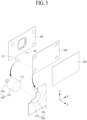
- FIG. 5 is a perspective view for illustrating a display apparatus including a tiling coupler according to the third embodiment of the present disclosure.
- the display apparatus may comprise a back frame BF, a display panel DP, a height adjustment element 100 and a position adjustment element 200.
- the overall structure of the display apparatus having a tiling coupler according to the third embodiment may have very similar structure of the first emebodiment. The difference is on the detailed shape of the position adjustment element 200.
- the differences appeared in the third embodiment will be mainly described.
- the same drawings and reference numerals as in Fig. 3 that are not described refer to the first embodiment.
- the position adjustment element 200 may have an area and shape corresponding to the area and shape of the display panel DP.
- the position adjustment element 200 may have a rectangular shape same as the display panel DP, and may be joined to the rear surface of the display panel DP.
- the position adjustment element 200 may be attached to the rear surface of the display panel DP by an adhesive material.
- the position adjustment element 200 may have a frame structure surrounding and fixing the sides of the display panel DP. Since the display panels DP are assembled in a tiling manner to form a large-scaled display apparatus, the description will be focused on a structure of coupling to the back surface of the display panel DP for preventing the joints between the tiled display panels DP from becoming prominent.
- the position adjustment element 200 includes an attaching surface 210 and a position adjusting surface 220.
- the attaching surface 210 may be the portion for attaching to the rear surface of the display panel DP. Therefore, the attaching surface 210 may be attached to whole rear surface of the display panel DP.
- the position adjusting surface 220 is the portion extruded to the height adjustment element 100 from the attaching surface 210.
- the position adjustment element 200 may have a rectangular plate shape as shown in Fig. 5 .
- the position adjusting surface 220 may be a recessed portion from the attaching surface 210 as corresponding to the mount surface 111 of the height adjustment element 100.
- the position adjusting surface 220 may have a disc shape recessed from the attaching surface 210.
- the position adjusting surface 220 is a surface located on the mount surface 111 by the magnetic force of the mount 110. As the position adjusting surface 220 is settled on the mount surface 111, it may be freely moveable within the surface area of the mount surface 111 on the XY plane formed by the mount surface 111. Therefore, as the position adjusting surface 220 moves over the mount surface 111, the position on the XY plane of the display panel DP fixed to the position adjustment element 200 may be controlled or adjusted.
- the attaching surface 210 of the position adjustment element 200 may be engaged with the most rear surface of the display panel DP.
- the position adjusting surface 220 of the position adjustment element 200 may be contacted to the mount 110, the permanent magnet.
- the magnetic force may be degraded by the heat generated from the display panel DP. Therefore, it is preferable to have a structure for preventing the heat from being concentrated to the mount 110 which is a permanent magnet.
- the heat generated from the display panel DP may be effectively dissipated or discharged by forming the attaching surface 210 of the position adjustment element 200 covering the entire rear surface of the display panel DP with a metal material such as a soft magnetic material.
- the position adjustment element 200 contacting the permanent magnet mount 110 has a structure that partially protrudes from the attaching surface 210, thereby it has a structure that may minimize the transfer of heat to the position adjusting surface 220.
- the position adjustment element 200 according to the third embodiment may efficiently dissipate the heat of the display panel DP, and may protect the magnetic force of the height adjustment element 100, the permanent magnet, from the heat.
- the shape of the position adjustment element 200 according to the third embodiment may be applied to the position adjustment element 200 according to the second embodiment. In addition, it may also be applied to the position adjustment element 200 of the other embodiments described later.
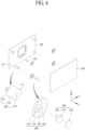
- Fig. 6 is a perspective view for illustrating a display apparatus including a tiling coupler according to the fourth embodiment of the present disclosure.
- Fig. 7 is a cross sectional view illustrating a structure of a display apparatus including a tiling coupler according to the fourth embodiment of the present disclosure shown in Fig. 6 .
- the display apparatus comprises a back frame BF, a display panel DP, a height adjustment element 100, a position adjustment element 200 and a position limiter 300.
- the back frame BF is configured to and may be attached and fixed on the wall structure using a fixing element AK.
- Each one of a plurality of display panels DP may be disposed as corresponding to a respective one of a plurality of back frames BF.
- the height adjustment element 100 may be a structure coupled or joined to the back frame BF and adjusted or controlled in height.
- the height adjustment element 100 is made of a permanent magnet.
- the height adjustment element 100 includes a mount 110 that my be cylindrical, a screw portion 120 and a base hole 130.
- the mount 110 and the screw portion 120 may be formed of a united body, or formed as separated objects and then combined.
- the screw portion 120 may have smaller diameter than the mount 110 and be extruded from the middle portion of the bottom surface of the mount 110.
- the screw portion 120 may be inserted into and coupled to a screw hole 121 provided at the back frame BF.
- the height of the mount 110 may be adjusted.
- the mount 110 is disposed on the screw portion 120 and facing the position adjustment element 200.
- the mount 110 includes a mount surface 111 having a predetermined surface area.
- a base hole 130 may be provided at the center of the mount surface 111.
- the base hole 130 may be a center portion of the mount surface 111 recessed into the mount 110 with a predetermined depth. Therefore, the mount surface 111 may be the circumference surface of the upper surface of the mount 110.
- Each of the position adjustment element 200 is fixed on the rear surface of the display panel DP as corresponding to each of the height adjustment element 100.
- the position adjustment element 200 is formed of a magnetic material which is attached by the magnetic force of the permanent magnet.
- the height adjustment element 100 is a permanent magnet
- the height adjustment element 100 may be made of a hard magnetic material such as Al-Ni-Co (Alumium-Nickel-Cobalt) alloy.
- the position adjustment element 200 may be made of soft magnetic material which is magnetized and seated on the height adjustment element 100 when it is within the magnetic force range of the height adjustment element 100. When the position adjustment element 200 is out of the magnetic force range of the height adjustment element 100, the magnetization is removed.
- the position adjustment element 200 includes an attaching surface 210, a position adjusting surface 220 and a position limiting hole 230.
- the attaching surface 210 may be a flat portion for attaching or fixing on the rear surface of the display panel DP. As shown in Fig. 6 , the position adjustment element 200 may have a disc shape, and the attaching surface 210 may have a disc ring shape corresponding to the outermost circumference of the position adjustment element 200.
- the position adjusting surface 220 is a protruding portion from the attaching surface 210 toward the height adjustment element 100.
- the position adjusting surface 220 may be a suppressed portion from the attaching surface 210 to have a disc shape surrounded by the attaching surface 210.
- the position limiting hole 230 may be a through hole formed at the center of the position adjusting surface 220. It is preferable that the position limiting hole 230 may have a larger diameter than the base hole 130 formed at the height adjustment element 100.
- This space is a space where the position limiter 300 may be arranged, and may be expressed as an adjusting chamber 240.
- the position limiter 300 has a T-shaped structure in which main portion is installed in the adjusting chamber 240 of the position adjustment element 200 and other portion is extruded through the position limiting hole 230.
- the position limiter 300 includes a head 310, an extrusion 330 and a cushion 320.
- the head 310 is a portion settling into the adjusting chamber 240.
- the head 310 may have a disc shape.
- the diameter of the head 310 is larger than the diameter of the position limiting hole 230 so that the head 310 is limitedly arranged inside the adjusting chamber 240.
- the extrusion 330 is a portion protruding toward the height adjustment element 100 from the center of the bottom surface of the head 310.
- the extrusion 330 may be inserted into the base hole 130 of the height adjustment element 100.
- the extrusion 330 may have a cylindrical shape having a diameter little smaller than the diameter of the base hole 130 and a length little shorter than the depth of the base hole 130.
- the extrusion 330 is inserted into the base hole 130 through the position limiting hole 230 starting from the head 310 located in the inner space of the adjusting chamber 240.
- the extrusion 330 may be corresponding to the protrusion portion 250 explained in the second embodiment shown in Fig. 4 .
- the upper surface of the head 310 may be a surface in close contact with the rear surface of the display panel DP.
- a friction force may occur between the head 310 and the rear surface of the display panel DP.
- the rear surface of the display panel DP may be damaged by this friction force.
- the cushion 320 is adhered to the upper surface of the head 310.
- the sum of the height of the head 310 and the cushion 320 may be equal to or slightly lower than the height of the adjusting chamber 240. That is, the sum of the heights of the head 310 and the cushion 320 may be equal to or slightly smaller than the height difference between the attaching surface 210 and the position adjusting surface 220 of the position adjustment element 200.
- the position limiting hole 230 has a diameter smaller than the diameter of the head 310 and larger than the diameter of the extrusion 330.
- the screw portion 120 of the height adjustment element 100 may be coupled to the screw hole 121 of the back frame BF.
- the position adjustment element 200 includes the position limiter 300, and is fixed to the display panel (e.g. it may be fixed on the rear surface of the display panel DP).
- the head 310 of the position limiter 300 may be located inside the adjusting chamber 240 of the position adjustment element 200, and the extrusion 330 may be protruding as penetrating the position limiting hole 230 of the position adjustment element 200.
- the extrusion 330 of the position limiter 300 is assembled while being inserted into the base hole 130 of the height adjustment element 100.
- the position adjustment element 200 may be positioned within the space between the position limiting hole 230 and the extrusion 330.
- the position may be adjusted on the XY plane formed by the mount surface 111.
- the range of the position may be limited within the range of the distance between the position limiting hole 230 and the extrusion 330.
- FIG. 8 is an enlarged cross-sectional view illustrating the configuration and the joining relationship of a tiling coupler in a display apparatus including the tiling coupler according to the fourth embodiment of the present disclosure shown in Fig. 6 .
- the screw hole 121 may be formed at the back frame BF.
- the height adjustment element 100 may be joined into the screw hole 121.
- the height adjustment element 100 includes a mount 110, a screw portion 120 and a base hole 130. It is preferable that the mount 110 may be made of a permanent magnet having a cylindrical shape.
- the screw portion 120 may be coupled to the lower part of the mount 110 and have the threads for engaging with the screw hole 121 formed at the back frame BF. Fastening the screw portion 120 into the screw hole 121, the height adjustment element 100 may be coupled to the back frame BF. As rotating the screw portion 120, according to the rotating direction, the height of the height adjustment element 100 may go up or down along the Z axis.
- the position adjustment element 200 includes an attaching surface 210, a position adjusting surface 220, a position limiting hole 230 and an adjusting chamber 240.
- One end portion of the position limiter 300 may be disposed in the adjusting chamber 240, and the other end portion of the position limiter 300 penetrates the position limiting hole 230 and be extruded to the height adjustment element 100.
- the position limiter 300 includes a head 310, an extrusion 330 and a cushion 320. As the head 310 is positioned inside the adjusting chamber 240 of the position adjustment element 200, the position limiter 300 may allow the position adjustment element 200 to move within a predetermined range with respect to the extrusion 330 on the XY plane. The extrusion 330 of the position limiter 300 is inserted into the base hole 130 of the height adjustment element 100.
- the force for mounting the display panel DP onto the back frame BF is the magnetic force of the height adjustment element 100. Therefore, even though the extrusion 330 is not firmly fastened to the base hole 130, there is no big problem in a state for the display panel DP to be seated on the back frame BF. However, in some cases, it may be required that the extrusion 330 and the base hole 130 are tightly coupled, so as to further prevent the display panel DP from being detached from the back frame BF by its own weight.
- the position adjusting surface 220 is compressed between the head 310 and the mount 110, it may effectively prevent the display panel DP from falling off the back frame BF. Accordingly, when a large-scaled display apparatus assembled by a tiling method is installed for a long time, it may be prevented from falling off the back frame BF or damaging the coupling structure due to the weight of the display panel DP.
- a plurality of back frame BF are disposed, and each of display panels DP is attached to each of the back frames BF, thereby a display apparatus having any suface area size may be easily implemented.
- the height adjustment element 100 provided at the back frame BF the height of each of the display panels DP may be exactly adjusted, so that all tiled display panels DP may be combined to have a same surface height on the Z axis.
- all tiled display panels DP may be in close contact with each other no gap therebetween.
- the position adjustment element 200 may be freely positioned under the condition that does not deviate from the range of the mount surface 111 on the XY plane. Therefore, the position adjustment element 200 may be effectively prevented from being detached from the height adjustment element 100 during the installation operation of the display apparatus.
- the present disclosure may provide a large-sized display apparatus coupled without the gaps of the seams on the same plane.
- the coupling force tiling the plurality of the display panels DP uses the magnetic force, there is an advantage of easy assembly and disassembly.
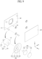
- FIG. 9 is a perspective view for illustrating a display apparatus including a tiling coupler according to the fifth embodiment of the present disclosure.
- the display apparatus comprises a back frame BF, a display panel DP, a height adjustment element 100, a position adjustment element 200 and a position limiter 300.
- Overall structure of the display apparatus having the tiling coupler according to the fifth embodiment may be very similar with that of the fourth embodiment.
- the main difference may be on the shape of the position limiting hole 230.
- the differences appeared in the fifth embodiment will be mainly described.
- the same drawings and reference numerals as in Fig. 6 that are not described refer to the fourth embodiment.
- the height adjustment element 100 includes a mount 110 that may be cylindrical, a screw portion 120 and a base hole 130.
- the screw portion 120 may be inserted into and coupled to a screw hole 121 provided at the back frame BF.
- the height of the mount 110 may be adjusted.
- the mount 110 may be disposed on the screw portion 120 and facing the position adjustment element 200.
- a base hole 130 may be provided at the center of the mount surface 111.
- the base hole 130 may be a center portion of the mount surface 111 recessed into the mount 110 with a predetermined depth.
- Each of the position adjustment element 200 may be fixed on the rear surface of the display panel DP as corresponding to each of the height adjustment element 100.
- the position adjustment element 200 is formed of a magnetic material which is attached by the magnetic force of the permanent magnet.
- the position adjustment element 200 includes an attaching surface 210, a position adjusting surface 220 and a position limiting hole 230.
- the attaching surface 210 may be a flat portion for attaching or fixing on the rear surface of the display panel DP.
- the position adjusting surface 220 is a protruding portion from the attaching surface 210 toward the height adjustment element 100. As the attaching surface 210 and the position adjusting surface 220 of the position adjustment element 200 have a height difference, an adjusting chamber 240 is formed therebetween.
- the position limiter 300 includes a head 310, an extrusion 330 and a cushion 320.
- the head 310 is a portion settling into the adjusting chamber 240.
- the extrusion 330 is a portion protruding from the center of the bottom surface of the head 310.
- the extrusion 330 may have a cylindrical shape having a diameter equal or little smaller than the diameter of the base hole 130 and a length little shorter than the depth of the base hole 130.
- the extrusion 330 is inserted into the base hole 130 through the position limiting hole 230 starting from the head 310 located in the inner space of the adjusting chamber 240.
- the cushion 320 is adhered to the upper surface of the head 310.
- the position limiting hole 230 may have an oval shape.
- the position limiting hole 230 may have a major (or long) axis and a minor (or short) axis.
- the minor axis of the position limiting hole 230 may have a length equal to or slightly larger than the diameter of the extrusion 330.
- the major aixs of the position limiting hole 230 may have a length and direction that limits the range of the movement of the position adjusting surface 220.
- the major axis of the position limiting hole 230 may be arranged in a diagonal direction of 45 degree to 225 degree on the XY plane of the display panel DP according to the coordinate axes of Fig. 9 .
- the major axis of the position limiting hole 230 may be arranged in a diagonal direction of 135 degree to 275 degree on the XY plane of the display panel DP.
- the major axis of the position limiting hole 230 may be larger than the diameter of the head 310, but the minor axis of the position limiting hole 230 may be smaller than the diameter of the head 310. Even though the major axis of the position limiting hole 230 may be larger than the diameter of the head 310, the head 310 may not come out from the position limiting hole 230 due to that the minor axis of the position limiting hole 230 is smaller than the diameter of the head 310.
- the major axis may be in range of 1.5 times to 2.5 times of the minor axis.
- the extrusion 330 of the position limiter 300 is assembled while being inserted into the base hole 130 of the height adjustment element 100.
- the position adjustment element 200 may be coupled with the position limiter 300 tightly along the minor axis. Since the major axis of the position limiting hole 230 may be larger than the diameters of the position limiter 300 and base hole 130, the position of the extrusion 330 may be adjusted within a specific range along the major axis of the position limiting hole 230. In other words, while the position adjusting surface 220 of the position adjustment element 200 is seated on the mount surface 111 of the height adjustment element 100, the position may be adjusted on the XY plane formed by the mount surface 111 along the diagonal direction. Here, the range of the position may be limited within the range of the distance between the major axis of the position limiting hole 230 and the extrusion 330.
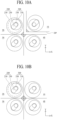
- FIGs. 10A and 10B are enlarged plan views illustrating an assembling process of 4 display panels including a tiling coupler according the fifth embodiment of the present disclosure.
- a fourth display panel may be assembled in the first quadrant 1S while three display panels DP may be already assembled in the second quadrant 2S, the third quadrant 3S and the fourth quadrant 4S, respectively.
- Fig. 10A shows a state in which the extrusion 330 is inserted into the base hole 130. On the XY plane, by combining in the direction biased in the 45 degree direction, assembling may be performed without any interference with the display panels DP that have been installed .
- the fourth display panel DP may be moved to 225 degree direction on the XY plane.
- the display panel DP for the first quadrant 1S may be completely assembled with the display panels DP of the second quadrant 2S, the third quadrant 3S and the fourth quadrant 4S.
- the heights of the display panels DP of the first quadrant 1S to the fourth quadrnat 4S may be uniformly matched.
- FIG. 11 is a cross-sectional view illustrating a display apparatus including a tiling coupler according to the sixth embodiment of the present disclosure.
- the sixth embodiment of the present disclosure will be described based on the cross-sectioal view.
- the display apparatus according to the sixth embodiment may be very similar with that of the fourth embodiment.
- the difference may be that a middle frame MF may be further included between the height adjustment element 100 and the position adjustment element 200.
- the middle frame MF may be an element for installing a devices additionally installed at the rear surface of the display panel DP.
- the middle frame MF may have a vessel shape for configuring to mount the sound generating device EX on the rear surface of the display panel DP.
- the middle frame MF may include a base surface M100, a mounting surface M200 and a link surface M300.
- the base surface M100 may be disposed between the position adjustment element 200 and the height adjustment element 100.
- the mounting surface M200 may be a protruding portion from the base surface M100 toward the back frame BF, and may have a predeterminded size suitable for mounting a various devices.
- the link surface M300 may be a portion connecting the base surface M100 and the mounting surface M200 that may have a gentle bevel (or slanted plane) shape.
- the space between the mounting surface M200 and the rear surface of the display panel DP may have a volume suitable for the devices mounting therein.
- the space between the mounting surface M200 and the rear surface of the display panel DP may be corresponding to the height of the sound generating device EX.
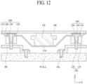
- FIG. 12 is a cross-sectional view illustrating a display apparatus including a tiling coupler according to the seventh embodiment of the present disclosure.
- the seventh embodiment of the present disclosure will be described based on the cross-sectional view.
- the display apparatus according to the seventh embodiment may be very similar with that of the fourth embodiment.
- the difference may be that the position adjustment element 200 may further include a space for installing the additional devices at the rear surface of the display panel DP.
- the position adjustment element 200 may further include an installing surface 270 for mounting a device so as to have a similar structure as the position adjustment element 200 according to the third embodiment as shown in Fig. 5 .
- the position adjustment element 200 of the display apparatus according to the seventh embodiment includes an attaching surface 210, a position adjusting surface 220, a position limiting hole 230 and may include an installing surface 270.
- the attaching surface 210 may be a flat portion for attaching or fixing on the rear surface of the display panel DP.
- the position adjusting surface 220 is a protruding portion from the attaching surface 210 toward the back frame BF.
- the position adjusting surface 220 may be the portion for coupling to the mount 110 of the height adjustment element 100.
- the position limiting hole 230 may be a through hole formed at the center of the position adjusting surface 220.
- the installing surface 270 may have a space formed by protruding to the back frame BF from the position adjusting surface 220. It is preferable that the installing surface 270 may have a vessel shape for mounting the devices installed at the rear surface of the display panel DP.
- the position adjustment element 200 of the display apparatus according to the seventh embodiment may have a structure with the structure of the middle frame MF (as shown in FIG. 7 ) embedded therein.
- a large-sized display apparatus may be formed by arranging a plurality of display panels DP having a device such as the sound generating device EX in a matrix manner.
- a large-sized display apparatus may be formed by arranging a plurality of display panels in which some of the display panels DP having the sound generating device EX may be configured as shown in Fig. 12 , and the other display panels DP without the sound generating device may be configured as shown in Fig. 7 .
- FIG. 13 is a perspective view illustrating a display apparatus including a tiling coupler according to the eighth embodiment of the present disclosure.
- the display apparatus according to the eighth embodiment may further include a levelizer (or horizontal holding member).
- a levelizer or horizontal holding member.
- the main feature of the eighth embodiment may be applied to the display apparatuses having the tiling coupler according to the first to seventh embodiments explained in previous.
- the display apparatus comprises a back frame BF, a display panel DP, a height adjustment element 100, a position adjustment element 200 and may comprise a levelizer 500.
- the back frame BF is configured to and may be attached and/or fixed onto the wall structure WALL (see FIG. 1 ) using a fixing element AK.
- the display panel DP may be arranged as corresponding to the back frame BF.
- the display panel DP may include a liquid crystal display panel, an electroluminescent display panel, a quantum dot display panel and/or other flat display panel.
- the height adjustment element 100 is a structure mounted into the back frame BF and capable of adjusting its height.
- the height adjustment element 100 is made of a permernant magnet material.
- the height adjustment element 100 includes a mount 110 that may be cylindrical and a screw portion 120.
- the screw portion 120 may be inserted into and coupled to a screw hole 121 provided at the back frame BF.
- the height of the mount 110 may be controlled by rotating the screw portion 120.
- the screw portion 120 may be a right-handed screw. As rotating to right-hand direction, the mount 110 may move to - Z direction, while as rotating to left-hand direction, the mount 110 may move to + Z direction. Accordingly, due to the rotation of the screw portion 120, the height on the Z axis of the mount surface 111 of the mount 110 may be controlled.
- each one of the position adjustment element 200 may be fixed on the rear surface of the display panel DP as corresponding to each one of the height adjustment element 100.
- the position adjustment element 200 is formed of a magnetic material that can be attached by the magnetic force of the permanent magnet.
- the position adjustment element 200 includes an attaching surface 210 and a position adjusting surface 220.
- the attaching surface 210 is a portion for fixing on the rear surface of the display panel DP.
- the position adjusting surface 220 is a protruding portion from the attaching surface 210 toward the height adjustment element 100.
- the position adjusting surface 220 is a surface settled on the mount surface 111 by the magnetic force of the mount 110.
- the position adjusting surface 220 is settled or mounted on the mount surface 111, and may be freely moved (or movable) within the area of the mount surface 111 on the XY plane formed by the mount surface 111. As the position adjusting surface 220 moves on the mount surface 111, the position on the XY plane of the display panel DP fixed to the position adjustment element 200 can be controlled or adjusted.
- the levelizer 500 may be a member for maintaining the horizontal state of the display panel DP by disposing between the display panel DP and the back frame BF.
- each set of height adjustment element 100 and position adjustment element 200 may be disposed at each of four corners of the display panel DP.
- the horizontal condition may be maintained using the height adjustment element 100 and position adjustment element 200 disposed at each corner of the display panel DP.
- the display panel has a relatively large area, i.e., more than 24 inch of diagonal length, any one side between two corners may be sagged.
- the entire display apparatus may be not maintained in uniformly flat condition, and a bumpy surface condition may occur. In this case, the quality of appearance may be deteriorated and a video image may be distorted.
- the eighth embodiment provides the levelizer 500 disposed at each side of the display panel DP.
- the levelizer 500 may have a very similar structure of the height adjustment element 100.
- the levelizer 500 may be a structure mounted into the back frame BF and capable of adjusting its height. It is preferable that the levelizer 500 may be made of a permernant magnet material.
- the levelizer 500 may include a cylindrical level mount 510, a level mount surface 511, a level screw portion 520 and a level cushion 530.
- the level screw portion 520 may be inserted into and coupled to a screw hole 121 provided at the back frame BF.
- the level screw portion 520 of the levelizer 500 may be same as the screw portion 120 of the height adjustment element 100.
- the level mount 510 may be made of a permanent magnet.
- the level mount 510 may be disposed on the level screw portion 520.
- the level mount 510 of the levelizer 500 may be same as the mount 110 of the height adjustment element 100.
- the level mount surface 511 may be defined as the surface disposed at the opposite side of the level screw portion 520 in the level mount 510.
- the level mount surface 511 may be a surface facing to the rear surface of the display panel DP.
- the level cushion 530 may be attached.
- the level mount 510 may be made of a magnetic material, it may be made of hard marterial such as metal. Therefore, when the level mount surface 511 of the level mount 510 may be directly contact with the rear surface of the display panel DP, the display panel DP may be damaged by the friction force of the level mount 510 as the level mount 510 is rotating, or the rotation of the level mount 510 may be not performed correctly.
- the level cushion 530 may be attached on the level mount surface 511. The level cushion 530 may directly contact with the rear surface of the display panel DP to reduce the friction force with the rear surface of the display panel DP and to protect the display panel DP.
- the height of the level mount 510 may be controlled. For example, rotating the levelizer 500 to right-handed direction, the level mount 510 may go down to -Z direction. Rotating the levelizer 500 to left-handed direction, the level mount 510 may go up to +Z direction. Therefore, the height of the level mount surface 511 of the level mount 510 may be controlled along the Z axis in accordance with the rotation of the level screw portion 520.
- a plurality of back frames BF are disposed and a display panel DP is attached to each of the back frames BF, thereby a display apparatus having any surface area size larger than the display panel DP may be implemented by combining the display panels DP in a tiling manner.
- the height of each display panel DP may be finely controlled using the height adjustment element 100 provided in the back frame BF, all tiled display panels DP may be combined as having the same surface height on the Z axis.
- the tiled display panels DP may be in close contact with each other having no gap therebetween.
- the position on the XY plane and the height on the Z axis may be respectively controlled or adjusted. Therefore, it is possible to provide a large-sized display apparatus that is combined without gaps of seams on the same plane.
- further comprising the levelizer 500 at the middle position of each side of the display panel DP it may prevent the problem of not being levelled by the sag of the middle part of the display panel DP.
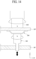
- Fig. 14 is a cross sectional view illustrating a mechanism for adjusting the height and position in the tiling coupler according to the present disclosure.
- the features explained referring to Fig. 14 may be applied to all embodiments previously described.
- the height of the surface of display panel may be adjusted with a height of the neighboring display panel.
- the height of the display panel may be controlled using the height adjustment element 100 having the permanent magnetic properties.
- the upper surface of the mount 110 may have any one pole of N pole and S pole.
- the height adjustment element 100 may be rotated over the upper surface of the display panel DP.
- the S pole of the magnetic driver tool MD may be contacted to the upper surface of the display panel DP, then the height adjustment element 100 and the magnetic driver tool MD may be attached by the magnetic attraction force. Under this condition, rotating the magnetic driver tool MD to left-handed direction or to right-handed direction, the height of the height adjustment element 100 may be controlled on the Z axis.
- the levelizer 500 described in the eighth embodiment also has the same structure as the height adjustment element 100, so that the height of the levelizer 500 may be controlled in the same manner.
- the surface height of the assembled large-sized display apparatus may be adjusted to have a constant level.
- the display apparatus according to the present disclosure may be easily and finely re-adjusted at any time when any level difference is occurred after completing the assembly.
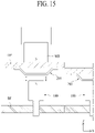
- FIG. 15 is a cross sectional view illustrating a process of disassembling a display panel from the back frame using the magnetic force in a display apparatus including the tiling coupler according to the present disclosure.
- the features of the present disclosure described referring to Fig. 15 may be applied to all embodiments previously explained.
- the most inconvenient and/or harder process in a large display apparatus formed by assembling a plurality of small display panel by tiling method is to separate one small display panel having a problem to repair after assembly. Under completely assembled state in which the small display panels are closely assembled so as not to recognize the seam portions, in order to separate one specific display panel, it is necessary to accurately lift off the display panel along the exact vertical direction, but this operation is very difficult.
- the present disclosure has a feature in that a unit display panel constituting a large-sized display apparatus may be removed from the assembled large display apparatus using the magnetic force.
- the large-sized display apparatus according to the present disclosure may have been assembled in a state as shown in Fig. 15.
- Fig. 15 shows one portion of assembled display apparatus according to the first embodiment.
- the upper surface of the mount 110 may have N pole or S pole.
- a magnetic separator MS made of a permanent magnet on the upper surface of the display panel DP, the display panel DP assembled with the position adjustment element 200 may be separated from the back frame BF assembled with the height adjustment element 100.
- the magnetic separator MS may have stronger magnetic force than the height adjustment element 100.
- the position adjustment element 200 is coupled to the height adjustment element 100 by the magnetic force, the position adjustment element 200 has been magnetized with N pole like the height adjustment element 100. Under this condition, when the magnetic separator MS has a magnetic force smaller than the height adjustment element 100, the magnetic separator MS may be pushed out by the magnetic force of the height adjustment element 100, and the display panel DP may not be separated.
- the position adjustment element 200 may be attached to the magnetic separator MS having the relatively larger magnetic force. Accordingly, the position adjustment element 200 may be magnetized with N pole like the magnetic separator MS. Then, the position adjustment element 200 may be easily separated from the height adjustment element 100 by the magnetic repulsive force between N pole and N pole.
- the magnetic driver tool MD explained in Fig. 14 and the magnetic separator MS explained in Fig. 15 are described as the different element.
- one magnetic tool may be configured to be used as a driver tool for rotating the height adjustment element 100 and as a separator for disassembling the display panel DP.
- the magnetic tool may be made of a permanant magent having a magnetic force larger than the height adjustment element 100.
- the magnetic tool has a structure that may be rotated so that N pole and S pole may be selected, or has a structure that can be separated and re-mounted after turning over.
- Fig. 16 is a diagram illustrating one example of a height adjustment element in a tiling coupler according to the present disclosure.
- the height adjustment element 100 may include a cylindrical mount 110 and a screw portion 120.
- the mount 110 and the screw portion 120 may be formed of a united body, or formed as separated objects and then combined.
- the screw portion 120 may have a smaller diameter than the mount 110 and may have a structure protruding from the center of the lower surface of the mount 110.
- a thread is formed in a lower portion to define the screw portion 120, and the upper portion may be defined as the mount 110.
- the mount 110 may be disposed on the screw portion 120 and facing with the position adjustment element 200.
- the upper surface of the mount 110 may be defined as a flat mount surface 111 having a predetermined area.
- the mount 110 may have a 4 pole structure.
- the cylindrical mount 110 may be divided into four sections in a plane view, and each of the 4 fan-shaped pillar portions (or 4 fan-shaped columns) may have been magnetized alternately.
- the mount surface 111 may include a first quadrant magnetized with N pole, a second quadrant magnetized with S pole, a third quadrant magnetized with N pole and a fourth quadrant magnetized with S pole, in a counter clockwise direction.
- the screw portion 120 may be made of a demagnetized material.
- the magnetic driver tool MD explained in Fig. 14 and the magnetic separator MS explained in Fig. 15 may have the 4 poles structure also.
- the magnetic heads of the magnetic driver tool MD and the magnetic separator MS may be configured to be rotable to set the magnetic head for selectively having the same pole or the different pole with the height adjustment element 100.
- FIG. 17 is an enlarged cross sectional view illustrating a structure of joining portion in a display apparatus including a tiling coupler according to the present disclosure.
- the display panel DP has been described with a simple rectangular structure.
- disposing a plurality of display panels DP in close contact with each other and thus constructing a large display apparatus there may be an increased possibility of damage due to impact and friction between the sides of the display panels DP abutting each other.
- the detailed structure of the display panel DP may be as shown in Fig. 17 .
- this is one example for reducing the damages from the friction and impact between abutting sides of the display panels, so it is not limited thereto.
- the display apparatus may comprise a display panel DP, a cover plate CP and a damper DM.
- the cover plated CP may be attached on the upper surface of the display panel DP.
- the cover plate CP may have the same size as the display panel DP. Othewise, the cover plate CP may have slightly larger area than the display panel DP.
- the case where the cover plate CP has a slightly larger area than the display panel DP will be explained.
- the damper DM may be disposed at the circumferences of the display panel DP. It is preferable that the damper DM may have a minimum thickness. For example, when the cover plate CP is larger than the display panel DP, the damper DM may be coated as filling within the space between the cover plate CP and the display panel DP and surrounding the circumferences of the display panel DP, and slightly protruding from the edge sides of the display panel DP.
- the damper DM may be suppressed a little and then the display panels DP are assembled as the cover plates CP may be in closed with each other.
- the protruding amount of the cover plate CP out of the display panel DP i.e., the size difference between the cover plate CP and the display panel DP, may be minimized.
- the size difference is too large, the seam may be easily recognized so that the display quality may be degraded.
- the size difference is too small, an impact may occur when assembling in tiling manner or friction may occur when adjusting the height of the display panel DP, so that the display panels DP may be damaged.
- FIG. 18 is a cross sectional view illustrating aprocess of disassembling a unit display panel (or device) from a display apparatus assembled in a large scale by a tiling coupler according to the present disclosure.
- a separating device may be set on the surface of the display panel DP.
- the separation device may include a vaccum absorber VS, a handle HD and a magnetic separator MS.
- the vaccum absorber VS may be set on the middle portion of the display panel DP.
- the handle HD may be integrally formed with the vacuum adsorber VS.
- the magnetic separator MS may be set on the position corresponding to the position adjustment element 200.
- the vaccum adsorber VS may be attached to the display panel DP using the handle HD.
- the magnetic separator MS may be contacted the surface of the display panel DP, so that the position adjustment element 200 may be separated from the height adjustment element 100 as explained in Fig. 15 .
- the middle portion of the display panel DP may be curved up (or soar up) but the circumference portions may be curved down by the friction force with the dampers DM of the neighboring display panels DP.
- the display panel DP is bended, a gap is formed at the edge portions.
- the display panel DP may be easily disengaged or disassembled.
- the new normal unit display panel may be reassembled or re-engaged in the reverse order.
- the display panel DP may be exactly assembled in the large display apparatus by the magnetic force between the height adjustment element 100 and the position adjustment element 200.
Landscapes
- Physics & Mathematics (AREA)
- Engineering & Computer Science (AREA)
- General Physics & Mathematics (AREA)
- Theoretical Computer Science (AREA)
- Optics & Photonics (AREA)
- Nonlinear Science (AREA)
- General Engineering & Computer Science (AREA)
- Microelectronics & Electronic Packaging (AREA)
- Mathematical Physics (AREA)
- Chemical & Material Sciences (AREA)
- Crystallography & Structural Chemistry (AREA)
- Multimedia (AREA)
- Mechanical Engineering (AREA)
- Devices For Indicating Variable Information By Combining Individual Elements (AREA)
- Computer Hardware Design (AREA)
- Human Computer Interaction (AREA)
Claims (10)
- Eine Anzeigevorrichtung, aufweisend:ein Anzeigepanel (DP);einen hinteren Rahmen (BF), der so gestaltet ist, dass er durch ein Befestigungselement (AK) an einer Wandstruktur (WALL) befestigt werden kann;ein mit dem hinteren Rahmen (BF) verbundenes Höheneinstellelement (100) mit einem Permanentmagneten, wobei eine Höhe des Höheneinstellelements (100) einstellbar ist; undein Positionseinstellelement (200), das an einer hinteren Fläche des Anzeigepanels (DP) befestigt ist und ein magnetisches Material enthält, das durch eine magnetische Kraft des Höheneinstellelements (100) angebracht ist, und das eine Position, an der das Positionseinstellelement (200) angebracht ist, auf einer durch das Höheneinstellelement (100) definierten Ebene einstellt;dadurch gekennzeichnet, dassdas Positionseinstellelement (200) ferner aufweist:eine Befestigungsfläche (210), die an dem Anzeigepanel (DP) befestigt ist;eine Positionseinstellfläche (220), die von der Befestigungsfläche (210) in Richtung des Höheneinstellelements (100) vorsteht;ein Positionsbegrenzungsloch (230), das an der Positionseinstellfläche (220) ausgebildet ist;eine Einstellkammer (240), die zwischen der Befestigungsfläche (210) und der Positionseinstellfläche (220) ausgebildet ist;wobei die Anzeigevorrichtung ferner einen Positionsbegrenzer (300) aufweist mit:einem Kopf (310), der in der Einstellkammer (240) angebracht ist;einer Extrusion (330), die von einem mittleren Abschnitt einer Bodenfläche des Kopfes (310) vorsteht; undeinem Kissen (320), das an einer oberen Fläche des Kopfes (310) befestigt ist,wobei das Positionsbegrenzungsloch (230) einen Durchmesser hat, der kleiner als der des Kopfes (310) und größer als der der Extrusion (330) ist, undwobei die Extrusion (330) so konfiguriert ist, dass sie das Positionsbegrenzungsloch (230) durchdringt und in ein Basisloch (130) des Höheneinstellelements (100) eingesetzt ist;wobei das Höheneinstellelement (100) aufweist:einen Schraubenteil (120), der mit dem hinteren Rahmen (BF) verbunden ist und zum Einstellen der Höhe konfiguriert ist; undeine Halterung (110), die an dem Schraubenteil (120) angeordnet ist und dem Positionseinstellelement (200) gegenüberliegt;wobei die Positionseinstellfläche (220) durch die Magnetkraft des Höheneinstellelements (100) auf einer an einer oberen Fläche der Halterung (110) definierten Halterungsfläche (111) aufgesetzt ist und so konfiguriert ist, dass sie die Position der Positionseinstellfläche (220) auf einer Ebene der Halterungsfläche (111) durch eine äußere Kraft ändert;wobei die Positionseinstellfläche (220) so konfiguriert ist, dass sie innerhalb des Bereichs der Halterungsfläche (111) auf einer durch die Halterungsfläche (111) gebildeten XY-Ebene frei beweglich ist, undwobei eine angeordnete Höhe des Anzeigepanels (DP) durch das Höheneinstellelement (100) steuerbar ist, und die Höhe des Anzeigepanels (DP) auf einer Z-Achse einstellbar ist.
- Die Anzeigevorrichtung nach Anspruch 1, wobei der Schraubenteil (120) in ein Schraubenloch (121) des hinteren Rahmens (BF) eingesetzt ist und die Höhe durch einen Drehvorgang einstellbar ist.
- Die Anzeigevorrichtung nach Anspruch 1, wobei das Höheneinstellelement (100) ferner aufweist:das Basisloch (130), das dem Positionseinstellelement (200) zugewandt ist, undwobei das Positionseinstellelement (200) ferner aufweist:
den Positionsbegrenzer (300), der in das Basisloch (130) des Höheneinstellelements (100) eingesetzt ist und so konfiguriert ist, dass er einen Positionsbereich des Anzeigepanels (DP) begrenzt. - Die Anzeigevorrichtung nach Anspruch 3, wobei ein Innendurchmesser des Basislochs (130) größer ist als ein Außendurchmesser des Positionsbegrenzers (300), und
wobei der Positionsbegrenzer (300) innerhalb eines Differenzbereichs zwischen dem Innendurchmesser und dem Außendurchmesser in der durch das Höheneinstellelement (100) definierten Ebene durch die äußere Kraft steuerbar ist. - Die Anzeigevorrichtung nach Anspruch 1, wobei das Positionsbegrenzungsloch (230) eine ovale Form mit einer Hauptachse und einer Nebenachse aufweist,wobei die Nebenachse eine Länge hat, die einem Durchmesser der Extrusion (330) entspricht, undwobei die Hauptachse eine Länge hat, die größer ist als der Durchmesser der Extrusion (330), und in einer diagonalen Richtung auf einer Oberfläche des Anzeigepanels (DP) angeordnet ist.
- Die Anzeigevorrichtung nach einem der Ansprüche 1 bis 5, wobei eine Vielzahl von Höheneinstellelementen (100) mit dem hinteren Rahmen (BF) verbunden sind und eine Vielzahl von Positionseinstellelementen (200) an der hinteren Fläche des Anzeigepanels (DP) befestigt sind, und
wobei jedes der Positionseinstellelemente (200) an dem Anzeigepanel (DP) so angeordnet ist, dass es einem entsprechenden der Höheneinstellelemente (100) entspricht. - Die Anzeigevorrichtung nach einem der Ansprüche 1 bis 6, ferner aufweisend:
einen Nivellierer (500), der am hinteren Rahmen (BF) getrennt vom Höheneinstellelement (100) angeordnet ist. - Die Anzeigevorrichtung nach Anspruch 6, ferner eine Vielzahl von Nivellierern (500) aufweisend, die an dem hinteren Rahmen (BF) getrennt von den Höheneinstellelementen (100) angeordnet sind, wobei jedes der Höheneinstellelemente (100) an einer entsprechenden Ecke des hinteren Rahmens (BF) angeordnet ist, und
wobei jeder der Nivellierer (500) an einem mittleren Abschnitt einer jeweiligen Seite des hinteren Rahmens (BF) angeordnet ist. - Die Anzeigevorrichtung nach einem der Ansprüche 1 bis 8, ferner aufweisend:einen mittleren Rahmen (MF), der zwischen dem Höheneinstellelement (100) und dem Positionseinstellelement (200) angeordnet ist und an der hinteren Fläche des Anzeigepanels (DP) angebracht ist, undwobei der mittlere Rahmen (MF) eine Gefäßform hat, die so konfiguriert ist, dass sie in Richtung des hinteren Rahmens (BF) vorsteht, um einen Raum für die Montage eines Geräts zu gewährleisten.
- Die Anzeigevorrichtung nach einem der Ansprüche 1 bis 9, wobei das Höheneinstellelement (100) einen zylindrischen Körper aufweist, der ein Neodym-Magnetmaterial aufweist oder daraus besteht, und/oder
wobei das Höheneinstellelement (100) in 4 fächerförmige Säulen unterteilt ist, die abwechselnd mit N- und S-Pol magnetisiert sind.
Applications Claiming Priority (1)
| Application Number | Priority Date | Filing Date | Title |
|---|---|---|---|
| KR1020190093336A KR102642789B1 (ko) | 2019-07-31 | 2019-07-31 | 표시 장치 |
Publications (2)
| Publication Number | Publication Date |
|---|---|
| EP3772052A1 EP3772052A1 (de) | 2021-02-03 |
| EP3772052B1 true EP3772052B1 (de) | 2023-03-22 |
Family
ID=71894678
Family Applications (1)
| Application Number | Title | Priority Date | Filing Date |
|---|---|---|---|
| EP20188613.2A Active EP3772052B1 (de) | 2019-07-31 | 2020-07-30 | Anzeigevorrichtung |
Country Status (4)
| Country | Link |
|---|---|
| US (1) | US12078285B2 (de) |
| EP (1) | EP3772052B1 (de) |
| KR (1) | KR102642789B1 (de) |
| CN (1) | CN112309267B (de) |
Families Citing this family (18)
| Publication number | Priority date | Publication date | Assignee | Title |
|---|---|---|---|---|
| KR102421442B1 (ko) * | 2018-01-31 | 2022-07-18 | 엘지전자 주식회사 | 멀티 디스플레이 디바이스 |
| KR102344490B1 (ko) * | 2020-08-31 | 2021-12-28 | 엘지전자 주식회사 | 멀티 디스플레이 장치 |
| KR102807721B1 (ko) * | 2020-11-09 | 2025-05-13 | 엘지디스플레이 주식회사 | 표시 장치 및 타일링 표시 장치 |
| CN214042924U (zh) * | 2020-12-24 | 2021-08-24 | 北京京东方光电科技有限公司 | 用于拼接屏的安装结构及拼接屏 |
| CN115637829B (zh) * | 2021-07-20 | 2026-02-24 | 中移(成都)信息通信科技有限公司 | 一种地板元及全向移动装置 |
| CN113934040B (zh) * | 2021-10-29 | 2023-11-28 | 武汉华星光电技术有限公司 | 一种显示装置 |
| CN116206538A (zh) * | 2021-12-01 | 2023-06-02 | 海信视像科技股份有限公司 | 显示屏 |
| KR20230103067A (ko) * | 2021-12-31 | 2023-07-07 | 엘지디스플레이 주식회사 | 간격조절부재 및 이를 포함하는 고정장치 |
| CN116724350A (zh) * | 2022-01-07 | 2023-09-08 | 京东方科技集团股份有限公司 | 显示模组的组装件、显示模组和拼接显示装置 |
| JPWO2023176190A1 (de) * | 2022-03-16 | 2023-09-21 | ||
| WO2023181246A1 (ja) * | 2022-03-24 | 2023-09-28 | アルディーテック株式会社 | 半導体発光素子チップ集積装置およびその製造方法 |
| CN114743470B (zh) * | 2022-04-24 | 2024-04-30 | 东莞市中麒光电技术有限公司 | 一种智能调节显示屏平整度的装置及其方法 |
| CN114999336B (zh) * | 2022-06-24 | 2025-05-09 | 京东方科技集团股份有限公司 | 子显示面板组件和拼接显示装置 |
| WO2024036596A1 (zh) * | 2022-08-19 | 2024-02-22 | 京东方科技集团股份有限公司 | 子显示面板组件和拼接显示装置 |
| WO2024065635A1 (zh) * | 2022-09-30 | 2024-04-04 | 京东方科技集团股份有限公司 | 承载箱体和拼接显示装置 |
| TWI814644B (zh) * | 2022-11-18 | 2023-09-01 | 友達光電股份有限公司 | 顯示裝置 |
| TWI852427B (zh) * | 2023-03-23 | 2024-08-11 | 友達光電股份有限公司 | 顯示面板之承載結構及包含其之顯示裝置 |
| CN116953975B (zh) * | 2023-07-26 | 2026-03-17 | 绵阳惠科光电科技有限公司 | 显示模组、显示装置及漏光调节方法 |
Family Cites Families (26)
| Publication number | Priority date | Publication date | Assignee | Title |
|---|---|---|---|---|
| JPS56108764A (en) * | 1980-01-30 | 1981-08-28 | Shionogi & Co Ltd | Novel synthesis of beta-blocker |
| US7213885B2 (en) * | 2005-06-10 | 2007-05-08 | Sac Acquistion Llc | Modular furniture assembly |
| JP2008242334A (ja) * | 2007-03-29 | 2008-10-09 | Nec Lcd Technologies Ltd | 液晶モジュール及びその液晶モジュールを備えた液晶表示装置 |
| US8727290B1 (en) * | 2010-08-11 | 2014-05-20 | Carlos De La Matta | Flat touch screen mounting system and method |
| KR101877061B1 (ko) * | 2012-03-23 | 2018-07-10 | 엘지전자 주식회사 | 디스플레이 장치 |
| US20160003270A1 (en) * | 2013-03-15 | 2016-01-07 | L. Christopher Franklin | Mounting apparatus |
| CN204178650U (zh) * | 2014-10-28 | 2015-02-25 | 深圳市创显光电有限公司 | 前维护型led显示模组及其显示屏 |
| GB2543966A (en) * | 2014-12-29 | 2017-05-03 | Planar Systems Inc | Mount with hidden magnetically actuated positioning |
| KR102009663B1 (ko) * | 2016-07-26 | 2019-10-21 | 삼성전자주식회사 | 디스플레이 장치의 결합 구조 및 디스플레이 장치 |
| US10741621B2 (en) * | 2016-11-25 | 2020-08-11 | Lg Display Co., Ltd. | Display device with a fingerprint sensor |
| EP3343047B1 (de) * | 2016-12-27 | 2023-11-22 | Lg Electronics Inc. | Anzeigevorrichtung |
| CN107038957B (zh) * | 2017-04-11 | 2020-02-07 | 深圳市雷迪奥视觉技术有限公司 | 卸载装置、自卸式显示装置 |
| JP6707191B2 (ja) * | 2017-05-10 | 2020-06-10 | 三菱電機株式会社 | マルチディスプレイシステム、映像表示装置および引出機構 |
| KR102305653B1 (ko) | 2017-05-23 | 2021-09-28 | 엘지디스플레이 주식회사 | 타일링 표시장치 |
| KR102415838B1 (ko) | 2017-11-28 | 2022-06-30 | 엘지디스플레이 주식회사 | 다중 패널 표시장치 |
| EP3499052B1 (de) * | 2017-12-15 | 2021-11-17 | LG Display Co., Ltd. | Gekachelte anzeigevorrichtung und kachelvorrichtung dafür |
| KR101895522B1 (ko) | 2017-12-15 | 2018-10-04 | 엘지디스플레이 주식회사 | 타일링 표시장치 및 이를 제작하는 타일링장치 |
| WO2019116524A1 (ja) * | 2017-12-15 | 2019-06-20 | 三菱電機株式会社 | 映像表示装置及びマルチディスプレイシステム |
| KR102421442B1 (ko) * | 2018-01-31 | 2022-07-18 | 엘지전자 주식회사 | 멀티 디스플레이 디바이스 |
| KR102455299B1 (ko) * | 2018-03-07 | 2022-10-17 | 엘지전자 주식회사 | 디스플레이 디바이스 |
| WO2020040616A1 (en) * | 2018-08-24 | 2020-02-27 | Samsung Electronics Co., Ltd. | Display apparatus |
| CN109442185B (zh) * | 2018-12-13 | 2020-06-09 | 杭州显迈科技有限公司 | 一种led显示屏安装装置 |
| KR102051604B1 (ko) * | 2018-12-14 | 2019-12-03 | 엘지디스플레이 주식회사 | 표시 장치, 타일링 표시 장치 및 타일링 표시 장치 제조 방법 |
| KR102593327B1 (ko) * | 2018-12-19 | 2023-10-25 | 엘지디스플레이 주식회사 | 디스플레이 설치장치 및 이를 포함하는 멀티디스플레이 |
| CN209149718U (zh) | 2018-12-28 | 2019-07-23 | 大道网络(上海)股份有限公司 | 一种屏幕框架组件及显示器组件 |
| KR102772129B1 (ko) * | 2019-09-05 | 2025-02-21 | 엘지디스플레이 주식회사 | 표시 장치 |
-
2019
- 2019-07-31 KR KR1020190093336A patent/KR102642789B1/ko active Active
-
2020
- 2020-07-30 CN CN202010750271.4A patent/CN112309267B/zh active Active
- 2020-07-30 US US16/943,679 patent/US12078285B2/en active Active
- 2020-07-30 EP EP20188613.2A patent/EP3772052B1/de active Active
Also Published As
| Publication number | Publication date |
|---|---|
| CN112309267A (zh) | 2021-02-02 |
| US12078285B2 (en) | 2024-09-03 |
| KR20210015058A (ko) | 2021-02-10 |
| EP3772052A1 (de) | 2021-02-03 |
| CN112309267B (zh) | 2023-04-07 |
| KR102642789B1 (ko) | 2024-02-29 |
| US20210033240A1 (en) | 2021-02-04 |
Similar Documents
| Publication | Publication Date | Title |
|---|---|---|
| US12078285B2 (en) | Display apparatus | |
| US11140467B2 (en) | Display apparatus | |
| US11353732B2 (en) | Display apparatus | |
| US11244998B2 (en) | Display device, tiling display device and method of manufacturing the same | |
| EP3667649B1 (de) | Mosaikanzeige und verfahren zur montage davon | |
| US10798830B2 (en) | Display apparatus | |
| EP3799656B1 (de) | Anzeigevorrichtung | |
| KR102807721B1 (ko) | 표시 장치 및 타일링 표시 장치 | |
| KR20190092968A (ko) | 멀티 디스플레이 디바이스 | |
| US20090289877A1 (en) | Display apparatuses and methods of fabricating the same | |
| US20240260213A1 (en) | Display device | |
| JP2004310023A (ja) | 液晶表示素子用基板貼り合せ装置 | |
| JP2007248498A (ja) | 表示装置 | |
| KR102741951B1 (ko) | 디스플레이 디바이스 | |
| US10775919B2 (en) | Display device | |
| US12237107B2 (en) | Mounting jig for manufacturing tiling display device, and tiling display device and manufacturing method therefor | |
| EP3614033B1 (de) | Anzeigevorrichtung | |
| US20250010605A1 (en) | Lamination device and driving method thereof | |
| KR102874291B1 (ko) | 타일링 표시 장치 제조용 마운팅 지그 및 타일링 표시 장치 제조 방법 |
Legal Events
| Date | Code | Title | Description |
|---|---|---|---|
| PUAI | Public reference made under article 153(3) epc to a published international application that has entered the european phase |
Free format text: ORIGINAL CODE: 0009012 |
|
| STAA | Information on the status of an ep patent application or granted ep patent |
Free format text: STATUS: REQUEST FOR EXAMINATION WAS MADE |
|
| 17P | Request for examination filed |
Effective date: 20200730 |
|
| AK | Designated contracting states |
Kind code of ref document: A1 Designated state(s): AL AT BE BG CH CY CZ DE DK EE ES FI FR GB GR HR HU IE IS IT LI LT LU LV MC MK MT NL NO PL PT RO RS SE SI SK SM TR |
|
| AX | Request for extension of the european patent |
Extension state: BA ME |
|
| RBV | Designated contracting states (corrected) |
Designated state(s): AL AT BE BG CH CY CZ DE DK EE ES FI FR GB GR HR HU IE IS IT LI LT LU LV MC MK MT NL NO PL PT RO RS SE SI SK SM TR |
|
| STAA | Information on the status of an ep patent application or granted ep patent |
Free format text: STATUS: EXAMINATION IS IN PROGRESS |
|
| 17Q | First examination report despatched |
Effective date: 20220331 |
|
| GRAP | Despatch of communication of intention to grant a patent |
Free format text: ORIGINAL CODE: EPIDOSNIGR1 |
|
| STAA | Information on the status of an ep patent application or granted ep patent |
Free format text: STATUS: GRANT OF PATENT IS INTENDED |
|
| RIC1 | Information provided on ipc code assigned before grant |
Ipc: G09F 9/35 20060101ALN20220922BHEP Ipc: G09F 9/33 20060101ALN20220922BHEP Ipc: G09F 9/302 20060101AFI20220922BHEP |
|
| INTG | Intention to grant announced |
Effective date: 20221011 |
|
| GRAS | Grant fee paid |
Free format text: ORIGINAL CODE: EPIDOSNIGR3 |
|
| GRAA | (expected) grant |
Free format text: ORIGINAL CODE: 0009210 |
|
| STAA | Information on the status of an ep patent application or granted ep patent |
Free format text: STATUS: THE PATENT HAS BEEN GRANTED |
|
| AK | Designated contracting states |
Kind code of ref document: B1 Designated state(s): AL AT BE BG CH CY CZ DE DK EE ES FI FR GB GR HR HU IE IS IT LI LT LU LV MC MK MT NL NO PL PT RO RS SE SI SK SM TR |
|
| REG | Reference to a national code |
Ref country code: GB Ref legal event code: FG4D |
|
| REG | Reference to a national code |
Ref country code: CH Ref legal event code: EP |
|
| REG | Reference to a national code |
Ref country code: IE Ref legal event code: FG4D |
|
| REG | Reference to a national code |
Ref country code: DE Ref legal event code: R096 Ref document number: 602020008978 Country of ref document: DE |
|
| REG | Reference to a national code |
Ref country code: AT Ref legal event code: REF Ref document number: 1555785 Country of ref document: AT Kind code of ref document: T Effective date: 20230415 |
|
| REG | Reference to a national code |
Ref country code: LT Ref legal event code: MG9D |
|
| REG | Reference to a national code |
Ref country code: NL Ref legal event code: MP Effective date: 20230322 |
|
| PG25 | Lapsed in a contracting state [announced via postgrant information from national office to epo] |
Ref country code: RS Free format text: LAPSE BECAUSE OF FAILURE TO SUBMIT A TRANSLATION OF THE DESCRIPTION OR TO PAY THE FEE WITHIN THE PRESCRIBED TIME-LIMIT Effective date: 20230322 Ref country code: NO Free format text: LAPSE BECAUSE OF FAILURE TO SUBMIT A TRANSLATION OF THE DESCRIPTION OR TO PAY THE FEE WITHIN THE PRESCRIBED TIME-LIMIT Effective date: 20230622 Ref country code: LV Free format text: LAPSE BECAUSE OF FAILURE TO SUBMIT A TRANSLATION OF THE DESCRIPTION OR TO PAY THE FEE WITHIN THE PRESCRIBED TIME-LIMIT Effective date: 20230322 Ref country code: LT Free format text: LAPSE BECAUSE OF FAILURE TO SUBMIT A TRANSLATION OF THE DESCRIPTION OR TO PAY THE FEE WITHIN THE PRESCRIBED TIME-LIMIT Effective date: 20230322 Ref country code: HR Free format text: LAPSE BECAUSE OF FAILURE TO SUBMIT A TRANSLATION OF THE DESCRIPTION OR TO PAY THE FEE WITHIN THE PRESCRIBED TIME-LIMIT Effective date: 20230322 |
|
| REG | Reference to a national code |
Ref country code: AT Ref legal event code: MK05 Ref document number: 1555785 Country of ref document: AT Kind code of ref document: T Effective date: 20230322 |
|
| PG25 | Lapsed in a contracting state [announced via postgrant information from national office to epo] |
Ref country code: SE Free format text: LAPSE BECAUSE OF FAILURE TO SUBMIT A TRANSLATION OF THE DESCRIPTION OR TO PAY THE FEE WITHIN THE PRESCRIBED TIME-LIMIT Effective date: 20230322 Ref country code: NL Free format text: LAPSE BECAUSE OF FAILURE TO SUBMIT A TRANSLATION OF THE DESCRIPTION OR TO PAY THE FEE WITHIN THE PRESCRIBED TIME-LIMIT Effective date: 20230322 Ref country code: GR Free format text: LAPSE BECAUSE OF FAILURE TO SUBMIT A TRANSLATION OF THE DESCRIPTION OR TO PAY THE FEE WITHIN THE PRESCRIBED TIME-LIMIT Effective date: 20230623 Ref country code: FI Free format text: LAPSE BECAUSE OF FAILURE TO SUBMIT A TRANSLATION OF THE DESCRIPTION OR TO PAY THE FEE WITHIN THE PRESCRIBED TIME-LIMIT Effective date: 20230322 |
|
| PG25 | Lapsed in a contracting state [announced via postgrant information from national office to epo] |
Ref country code: SM Free format text: LAPSE BECAUSE OF FAILURE TO SUBMIT A TRANSLATION OF THE DESCRIPTION OR TO PAY THE FEE WITHIN THE PRESCRIBED TIME-LIMIT Effective date: 20230322 Ref country code: RO Free format text: LAPSE BECAUSE OF FAILURE TO SUBMIT A TRANSLATION OF THE DESCRIPTION OR TO PAY THE FEE WITHIN THE PRESCRIBED TIME-LIMIT Effective date: 20230322 Ref country code: PT Free format text: LAPSE BECAUSE OF FAILURE TO SUBMIT A TRANSLATION OF THE DESCRIPTION OR TO PAY THE FEE WITHIN THE PRESCRIBED TIME-LIMIT Effective date: 20230724 Ref country code: ES Free format text: LAPSE BECAUSE OF FAILURE TO SUBMIT A TRANSLATION OF THE DESCRIPTION OR TO PAY THE FEE WITHIN THE PRESCRIBED TIME-LIMIT Effective date: 20230322 Ref country code: EE Free format text: LAPSE BECAUSE OF FAILURE TO SUBMIT A TRANSLATION OF THE DESCRIPTION OR TO PAY THE FEE WITHIN THE PRESCRIBED TIME-LIMIT Effective date: 20230322 Ref country code: AT Free format text: LAPSE BECAUSE OF FAILURE TO SUBMIT A TRANSLATION OF THE DESCRIPTION OR TO PAY THE FEE WITHIN THE PRESCRIBED TIME-LIMIT Effective date: 20230322 |
|
| PG25 | Lapsed in a contracting state [announced via postgrant information from national office to epo] |
Ref country code: SK Free format text: LAPSE BECAUSE OF FAILURE TO SUBMIT A TRANSLATION OF THE DESCRIPTION OR TO PAY THE FEE WITHIN THE PRESCRIBED TIME-LIMIT Effective date: 20230322 Ref country code: PL Free format text: LAPSE BECAUSE OF FAILURE TO SUBMIT A TRANSLATION OF THE DESCRIPTION OR TO PAY THE FEE WITHIN THE PRESCRIBED TIME-LIMIT Effective date: 20230322 Ref country code: IS Free format text: LAPSE BECAUSE OF FAILURE TO SUBMIT A TRANSLATION OF THE DESCRIPTION OR TO PAY THE FEE WITHIN THE PRESCRIBED TIME-LIMIT Effective date: 20230722 |
|
| REG | Reference to a national code |
Ref country code: DE Ref legal event code: R097 Ref document number: 602020008978 Country of ref document: DE |
|
| PLBE | No opposition filed within time limit |
Free format text: ORIGINAL CODE: 0009261 |
|
| STAA | Information on the status of an ep patent application or granted ep patent |
Free format text: STATUS: NO OPPOSITION FILED WITHIN TIME LIMIT |
|
| PG25 | Lapsed in a contracting state [announced via postgrant information from national office to epo] |
Ref country code: SI Free format text: LAPSE BECAUSE OF FAILURE TO SUBMIT A TRANSLATION OF THE DESCRIPTION OR TO PAY THE FEE WITHIN THE PRESCRIBED TIME-LIMIT Effective date: 20230322 Ref country code: DK Free format text: LAPSE BECAUSE OF FAILURE TO SUBMIT A TRANSLATION OF THE DESCRIPTION OR TO PAY THE FEE WITHIN THE PRESCRIBED TIME-LIMIT Effective date: 20230322 Ref country code: CZ Free format text: LAPSE BECAUSE OF FAILURE TO SUBMIT A TRANSLATION OF THE DESCRIPTION OR TO PAY THE FEE WITHIN THE PRESCRIBED TIME-LIMIT Effective date: 20230322 |
|
| 26N | No opposition filed |
Effective date: 20240102 |
|
| PG25 | Lapsed in a contracting state [announced via postgrant information from national office to epo] |
Ref country code: MC Free format text: LAPSE BECAUSE OF FAILURE TO SUBMIT A TRANSLATION OF THE DESCRIPTION OR TO PAY THE FEE WITHIN THE PRESCRIBED TIME-LIMIT Effective date: 20230322 |
|
| PG25 | Lapsed in a contracting state [announced via postgrant information from national office to epo] |
Ref country code: MC Free format text: LAPSE BECAUSE OF FAILURE TO SUBMIT A TRANSLATION OF THE DESCRIPTION OR TO PAY THE FEE WITHIN THE PRESCRIBED TIME-LIMIT Effective date: 20230322 |
|
| REG | Reference to a national code |
Ref country code: CH Ref legal event code: PL |
|
| REG | Reference to a national code |
Ref country code: BE Ref legal event code: MM Effective date: 20230731 |
|
| PG25 | Lapsed in a contracting state [announced via postgrant information from national office to epo] |
Ref country code: LU Free format text: LAPSE BECAUSE OF NON-PAYMENT OF DUE FEES Effective date: 20230730 |
|
| PG25 | Lapsed in a contracting state [announced via postgrant information from national office to epo] |
Ref country code: LU Free format text: LAPSE BECAUSE OF NON-PAYMENT OF DUE FEES Effective date: 20230730 |
|
| REG | Reference to a national code |
Ref country code: IE Ref legal event code: MM4A |
|
| PG25 | Lapsed in a contracting state [announced via postgrant information from national office to epo] |
Ref country code: CH Free format text: LAPSE BECAUSE OF NON-PAYMENT OF DUE FEES Effective date: 20230731 |
|
| PG25 | Lapsed in a contracting state [announced via postgrant information from national office to epo] |
Ref country code: IT Free format text: LAPSE BECAUSE OF FAILURE TO SUBMIT A TRANSLATION OF THE DESCRIPTION OR TO PAY THE FEE WITHIN THE PRESCRIBED TIME-LIMIT Effective date: 20230322 Ref country code: BE Free format text: LAPSE BECAUSE OF NON-PAYMENT OF DUE FEES Effective date: 20230731 |
|
| PG25 | Lapsed in a contracting state [announced via postgrant information from national office to epo] |
Ref country code: IE Free format text: LAPSE BECAUSE OF NON-PAYMENT OF DUE FEES Effective date: 20230730 |
|
| PG25 | Lapsed in a contracting state [announced via postgrant information from national office to epo] |
Ref country code: IE Free format text: LAPSE BECAUSE OF NON-PAYMENT OF DUE FEES Effective date: 20230730 |
|
| PG25 | Lapsed in a contracting state [announced via postgrant information from national office to epo] |
Ref country code: BG Free format text: LAPSE BECAUSE OF FAILURE TO SUBMIT A TRANSLATION OF THE DESCRIPTION OR TO PAY THE FEE WITHIN THE PRESCRIBED TIME-LIMIT Effective date: 20230322 |
|
| PG25 | Lapsed in a contracting state [announced via postgrant information from national office to epo] |
Ref country code: BG Free format text: LAPSE BECAUSE OF FAILURE TO SUBMIT A TRANSLATION OF THE DESCRIPTION OR TO PAY THE FEE WITHIN THE PRESCRIBED TIME-LIMIT Effective date: 20230322 |
|
| PGFP | Annual fee paid to national office [announced via postgrant information from national office to epo] |
Ref country code: GB Payment date: 20250520 Year of fee payment: 6 |
|
| PGFP | Annual fee paid to national office [announced via postgrant information from national office to epo] |
Ref country code: FR Payment date: 20250521 Year of fee payment: 6 |
|
| PG25 | Lapsed in a contracting state [announced via postgrant information from national office to epo] |
Ref country code: CY Free format text: LAPSE BECAUSE OF FAILURE TO SUBMIT A TRANSLATION OF THE DESCRIPTION OR TO PAY THE FEE WITHIN THE PRESCRIBED TIME-LIMIT; INVALID AB INITIO Effective date: 20200730 |
|
| PG25 | Lapsed in a contracting state [announced via postgrant information from national office to epo] |
Ref country code: HU Free format text: LAPSE BECAUSE OF FAILURE TO SUBMIT A TRANSLATION OF THE DESCRIPTION OR TO PAY THE FEE WITHIN THE PRESCRIBED TIME-LIMIT; INVALID AB INITIO Effective date: 20200730 |
|
| PGFP | Annual fee paid to national office [announced via postgrant information from national office to epo] |
Ref country code: DE Payment date: 20250520 Year of fee payment: 6 |
|
| PG25 | Lapsed in a contracting state [announced via postgrant information from national office to epo] |
Ref country code: TR Free format text: LAPSE BECAUSE OF FAILURE TO SUBMIT A TRANSLATION OF THE DESCRIPTION OR TO PAY THE FEE WITHIN THE PRESCRIBED TIME-LIMIT Effective date: 20230322 |