EP3771773B1 - Verfahren zur herstellung eines cellulosenanofaserpresslings - Google Patents
Verfahren zur herstellung eines cellulosenanofaserpresslings Download PDFInfo
- Publication number
- EP3771773B1 EP3771773B1 EP20187312.2A EP20187312A EP3771773B1 EP 3771773 B1 EP3771773 B1 EP 3771773B1 EP 20187312 A EP20187312 A EP 20187312A EP 3771773 B1 EP3771773 B1 EP 3771773B1
- Authority
- EP
- European Patent Office
- Prior art keywords
- precursor
- equal
- heating
- mold
- cellulose nanofiber
- Prior art date
- Legal status (The legal status is an assumption and is not a legal conclusion. Google has not performed a legal analysis and makes no representation as to the accuracy of the status listed.)
- Active
Links
Images



Classifications
-
- D—TEXTILES; PAPER
- D21—PAPER-MAKING; PRODUCTION OF CELLULOSE
- D21H—PULP COMPOSITIONS; PREPARATION THEREOF NOT COVERED BY SUBCLASSES D21C OR D21D; IMPREGNATING OR COATING OF PAPER; TREATMENT OF FINISHED PAPER NOT COVERED BY CLASS B31 OR SUBCLASS D21G; PAPER NOT OTHERWISE PROVIDED FOR
- D21H11/00—Pulp or paper, comprising cellulose or lignocellulose fibres of natural origin only
- D21H11/16—Pulp or paper, comprising cellulose or lignocellulose fibres of natural origin only modified by a particular after-treatment
-
- D—TEXTILES; PAPER
- D21—PAPER-MAKING; PRODUCTION OF CELLULOSE
- D21H—PULP COMPOSITIONS; PREPARATION THEREOF NOT COVERED BY SUBCLASSES D21C OR D21D; IMPREGNATING OR COATING OF PAPER; TREATMENT OF FINISHED PAPER NOT COVERED BY CLASS B31 OR SUBCLASS D21G; PAPER NOT OTHERWISE PROVIDED FOR
- D21H15/00—Pulp or paper, comprising fibres or web-forming material characterised by features other than their chemical constitution
- D21H15/02—Pulp or paper, comprising fibres or web-forming material characterised by features other than their chemical constitution characterised by configuration
- D21H15/10—Composite fibres
-
- D—TEXTILES; PAPER
- D21—PAPER-MAKING; PRODUCTION OF CELLULOSE
- D21H—PULP COMPOSITIONS; PREPARATION THEREOF NOT COVERED BY SUBCLASSES D21C OR D21D; IMPREGNATING OR COATING OF PAPER; TREATMENT OF FINISHED PAPER NOT COVERED BY CLASS B31 OR SUBCLASS D21G; PAPER NOT OTHERWISE PROVIDED FOR
- D21H11/00—Pulp or paper, comprising cellulose or lignocellulose fibres of natural origin only
- D21H11/16—Pulp or paper, comprising cellulose or lignocellulose fibres of natural origin only modified by a particular after-treatment
- D21H11/18—Highly hydrated, swollen or fibrillatable fibres
-
- D—TEXTILES; PAPER
- D21—PAPER-MAKING; PRODUCTION OF CELLULOSE
- D21J—FIBREBOARD; MANUFACTURE OF ARTICLES FROM CELLULOSIC FIBROUS SUSPENSIONS OR FROM PAPIER-MACHE
- D21J3/00—Manufacture of articles by pressing wet fibre pulp, or papier-mâché, between moulds
Definitions
- This disclosure relates to a method of manufacturing a cellulose nanofiber compact.
- Nano fibers can be obtained generally by pulverizing pulp or the like under a water-dispersed state thereof. Therefore, in obtaining a compact (i.e. a molded product) of cellulose nanofibers (CNF) from slurry (water dispersion) of the cellulose nanofibers, the slurry needs to be dehydrated and molded (see e.g. Japanese Unexamined Patent Application No. 2018-059236 , Japanese Unexamined Patent Application No. 2016-094683 ).
- CNF cellulose nanofibers
- JP No. 2018-059236 discloses a method of manufacturing a cellulose nanofiber compact.
- This method includes a step of dehydrating slurry containing cellulose nanofibers through a mesh-like member. At this dehydrating step, a pressurizing force applied to the slurry is increased either stepwise or continuously.
- a pressurizing force applied to the slurry is increased either stepwise or continuously.
- JP No. 2016-094683 discloses a method of molding cellulose nanofibers as well as a CNF compact obtained by the molding method.
- a method of molding cellulose nanofibers as well as a CNF compact obtained by the molding method.
- into a mold formed by overlapping a porous body formed of such material as ceramics, resin, or the like and a rectangular stainless frame having one side open cellulose nanofiber containing slurry is charged and then another porous body is placed on this cellulose nanofiber containing slurry.
- a mesh or a membrane By wrapping the cellulose nanofiber containing slurry by a mesh or a membrane, leak from a gap between the mold and the porous body and clogging of the porous body can be suppressed.
- Cellulose nanofibers are a material capable of forming a compact (molded product) having high strength by firm bonding thereof through mutual physical intertwining or hydrogen bond.
- JP No. 2018-059236 and JP No. 2016-094683 it has been sometimes not possible to obtain a cellulose nanofiber compact having sufficient strength.
- a method of manufacturing a cellulose nanofiber compact comprises the features from claim 1, especially:
- the second precursor is a precursor of a compact of cellulose nanofibers (may be referred to as CNF hereinafter) (a molded product, which may be referred to simply as a "compact” hereinafter) obtained by the molding step.
- the first precursor is a precursor of the second precursor.
- heating of the first precursor supported in the heating vessel is implemented by irradiation of infrared rays (in particular, far infrared rays).
- infrared rays in particular, far infrared rays
- the molecules of CNF are applied with energy in the infrared range, so that vibration of chemical bond (in particular, the hydroxy group) occurs.
- vibration of chemical bond in particular, the hydroxy group
- side chains of the CNF molecules come closer to each other, thus promoting hydrogen bond among the CNF molecules.
- the strength of the compact e.g. its tensile modulus of elasticity or bending modulus of elasticity
- the purpose of heating is to promote the hydrogen bond, whereas progress of drying is not absolutely needed.
- the heating vessel is formed of ceramics.
- infrared rays in particular, far infrared rays
- both supporting of the first precursor and heating thereof with infrared rays can be realized.
- the heating vessel is constituted of a porous body defining many pores.
- the first precursor is heated, so that water will be evaporated from the first precursor.
- water content (water vapor) evaporated from the face of the first precursor facing the heating vessel can be passed through the pores of the heating vessel to be released to the outside.
- the first precursor is supported with cellophane being interposed between the first precursor and the heating vessel.
- the heating vessel is constituted of a porous body, it is possible to prevent the first precursor from flowing into the pores of the heating vessel, so that clogging of the heating vessel as a porous body can be prevented.
- the cellulose nanofiber containing slurry having a higher water content than the first precursor is condensed by microwave heating to evaporate the water in the slurry, whereby the first precursor can be obtained.
- the condensation of the cellulose nanofiber containing slurry is done by charging the cellulose nanofiber containing slurry into a bottomed cylindrical condensing vessel, and irradiating microwave to the cellulose nanofiber containing slurry reserved (charged) in the condensing vessel by means of e.g. a microwave heater or the like (microwave heating).
- a microwave heater or the like microwave heating
- the center portion of the cellulose nanofiber containing slurry is covered with a lid member.
- drying at an excessive rate can be avoided at the center portion the cellulose nanofiber containing slurry which portion tends to be more readily influenced by microwave irradiation by a microwave heater device or the like and drying tends to progress more positively than the portion of the reserved cellulose nanofiber containing slurry located near the lateral wall of the condensing vessel (i.e. the outer circumferential portion of the reserved cellulose nanofiber containing slurry), whereby uniformity of drying rate between the center portion and the outer circumferential portion can be achieved. Consequently, it is possible to avoid the above-described inconvenience that excessive local drying occurs at an excessive rate at the center portion and resultantly a paper-like structure is formed before reinforcement of CNF is provided by hydrogen bond, thus inviting reduction in the strength of the resultant compact.
- the preliminary molding step includes an aging step of promoting the hydrogen bond between the nanocellulose fibers in the second precursor, with keeping the surface temperature of the heating vessel between equal to or higher than 50°C and equal to or lower than 120°C.
- the temperature of the first precursor at the preliminary molding step can be maintained between equal to or higher than 50°C and equal to or lower than 120°C. With this, it is possible to avoid drying of the first precursor before the progress of hydrogen bond, so that the hydrogen bond between the CNF molecules can be promoted while allowing the movements of the CNF molecules as well as vibration and movements of their side chains. Incidentally, if the drying progressed at an excessive rate at the preliminary molding step just like the condensing step, there could occur the inconvenience of the CNF in the first precursor forming a paper-like structure, thus leading to reduction in the strength of the compact.
- a method of manufacturing a cellulose nanofiber compact includes and carries out: a condensing step of condensing cellulose nanofiber containing slurry by microwave heating to obtain a first precursor; a supporting step of supporting a plate-like first precursor containing cellulose nanofibers on a surface of a heating vessel; a preliminary molding step of heating the first precursor supported in the heating vessel with infrared rays to obtain a plate-like second precursor; and a molding step of molding the second precursor with heating and pressurizing the second precursor in a mold, one after another in the mentioned order, thus realizing a cellulose nanofiber compact having high strength (e.g. tensile elasticity modulus or bending elasticity modulus).
- high strength e.g. tensile elasticity modulus or bending elasticity modulus
- the cellulose nanofibers may be referred to as "CNF" hereinafter) in this embodiment refer to fine cellulose fibers, which may have a fiber width (diameter of fiber, to be referred to as fiber diameter hereinafter) equal to or greater than 1 nm and equal to or less than 150 nm or less, a fiber length equal to or greater than 3 nm and less than 300 ⁇ m, for instance.
- An average fiber length of CNF can be determined by e.g. image analysis using a scanning electron microscope (SEM).
- An average fiber diameter of CNF can also be determined by image analysis using a scanning electron microscope (SEM), like the fiber length described above.
- SEM scanning electron microscope
- CNF containing slurry used in this embodiment, its CNF content preferably ranges equal to or greater than 0.5 mass% and less than 10 mass%, especially preferably, equal to or greater than 2 mass% and less than 6 mass%.
- the CNF containing slurry e.g. water dispersion containing 3 mass % of CNF, to be referred to simply as "slurry 10" hereinafter
- slurry 10 e.g. water dispersion containing 3 mass % of CNF, to be referred to simply as "slurry 10" hereinafter
- microwave e.g. having a frequency of 2.45 GHz
- a charging step, a covering step, an MW irradiating step and a stabilizing step are carried out.
- a bottomed cylindrical condensing vessel 20 water-permeable membranes 41, 42 and a plate-like lid member 25.
- the condensing vessel 20 includes a tubular portion 21 which can be cylindrical and a bottom plate 22 as a member separate from the tubular portion 21.
- the bottom plate 22 is a plate formed of porous ceramics.
- the bottom plate 22 due to its porosity, allows permeation of water vapor through its plate face.
- the tubular portion 21 is a tube formed of porous ceramics, as is the case with the bottom plate 22.
- the diameter of the tube of the tubular portion 21 is e.g. 5 cm.
- the water-permeable membranes 41, 42 are membrane materials that allow permeation of water or water vapor therethrough. These water-permeable membranes 41, 42 are thin membranes based on cellulose (a film formed of cellulose, so-called cellophane). The thickness of the water-permeable membranes 41, 42 is e.g. about 30 ⁇ m (300g/m 2 ) for instance, in the case of cellophane.
- the lid member 25 has a diameter slightly smaller than the inside diameter of the tubular portion 21 (e.g. about 80%) and comprises a plate formed of polyimide (e.g. having a thickness of 1.5 mm). The plate face of this lid member 25 is not permeable to water vapor.
- the water-permeable membrane 41 is placed to cover the bottom plate 22. Then, the tubular portion 21 is placed on this water-permeable membrane 41. In this placing, in this embodiment, the water-permeable membrane 41 is bound between the entire circumference of the bottom face of the tubular member 21 and the upper face of the bottom plate 22.
- a measured predetermined amount (e.g. 15 g) of slurry 10 is charged by e.g. flowing (one example of the "charging step").
- the slurry 10 will be spread over the water-permeable membrane 41 inside the condensing vessel 20 and formed into a film or membrane having a certain thickness (e.g. thickness from 3 mm to 5 mm).
- the CNF content of the slurry 10 is e.g. 3 mass%.
- the surface of the slurry 10 is covered by the lid member 25.
- the lid member 25 will be placed at the center portion in the upper face (surface) of the slurry 10, namely, at a position spaced apart from the entire inner circumference of the tubular portion 21 (the above represents one example of the "covering step").
- the slurry 10 will be subjected to heating by irradiation of microwave W thereto, by e.g. placing the condensing vessel 20 as a whole into a chamber of an electron microwave oven for industrial use (a microwave heater device, not shown) (this will be referred to as an "MW irradiating step" hereinafter).
- a microwave heater device not shown
- MW irradiating step water will be evaporated from the slurry 10 and the slurry 10 will be condensed, thereby to obtain a first precursor 11 (see Fig. 2 ).
- Figs. 1 and 2 show the dimensions and ratios with some deformation provided thereto for the sake of explanation of the embodiment, showing e.g. the thicknesses of the slurry 10, the first precursor 11 and the water-permeable membrane 41, etc. greater than their actual dimensions and ratios. This applies also to the illustrations of Fig. 3 and the drawings subsequent thereto.
- the lid member 25 As the upper surface center portion of the slurry 10 is covered with the lid member 25, it is possible to render uniform the degree of dryness between the center portion and the outer circumferential portion.
- the center portion of the slurry 10 is more susceptible to the irradiation of the microwave W inside the electron microwave oven, so that the drying there tends to progress more easily than the portion adjacent the lateral wall of the condensing vessel 20. For this reason, by covering this with the lid member 25, progress of drying at an excessive rate at the center portion (i.e. local excessive drying) and insufficient drying such as cracking associated therewith can be prevented. Further, with this prevention of local excessive drying, it is possible to prevent the inconvenience of forming of a paper-like structure prior to occurrence of reinforcement of CNF with the hydrogen bond, thus resulting in reduction in the strength of the compact.
- the irradiation is carried out for a total time of from 4 minutes to 8 minutes approximately, with a power of 200 W per 15g of the slurry 10, for instance.
- the microwave W is irradiated for 6 minutes.
- the irradiation of the microwave W e.g. about 7.5 g of first precursor 11 (see Fig. 2 ) can be obtained.
- the irradiation period should be reduced substantially in inverse proportion to this power.
- the irradiation period of the microwave W should be adjusted such that the mass of the resultant first precursor 11 (see Fig.2 ) may range from 45% to 55% relative to the slurry 10.
- the microwave W is irradiated for 2 minutes and the slurry 10 is inverted. Then, the microwave W is irradiated for another 2 minutes and the slurry 10 is inverted. Then, the microwave W is irradiated again for 1 minute and the slurry 10 is inverted. Lastly, the microwave W is irradiated for 1 minute, thereby to complete the MW irradiating step to obtain the first precursor 11 (see Fig. 2 ).
- the first precursor 11 will be molded into the form of a soft gel in a plate shape (disc shape) whose outer circumferential shape complies with the shape of the inner circumference of the cylinder of the tubular portion 21.
- the first precursor 11 may be left still for a predetermined period (e.g. 5 minutes) (this will be referred to as a "stabilizing step” hereinafter).
- a stabilizing step As the first precursor 11 is left still, irregularity of water contents of the respective portions within the first precursor 11 (e.g. between the upper and lower portion, between the center portion and the outer circumferential portion, etc.) is reduced, thus being rendered uniform.
- the first precursor 11 is covered by the water-permeable membrane 42, whereby the first precursor 11 is bound and wrapped between/by the two water-permeable membranes 41, 42.
- the condensing vessel 20 may be closed with a vessel lid 29.
- the vessel lid 29 isolates the inside of the condensing vessel 20 from the outside, thus preventing changing of air.
- progress of drying of the first precursor 11 left within the condensing vessel 20 is suspended temporarily, thereby to further reduce irregularity of water content in the first precursor 11 at the stabilizing step, thus rendering it even more uniform.
- the vessel lid 29 there is employed a porous ceramic plate.
- the humidity inside the condensing vessel 20 is kept high and at the same time, it is possible to avoid such inconvenience as occurrence of condensation on the inner face of the vessel lid 29 and/or the condensing vessel 20 and returning of condensed water to the first precursor 11, causing water content irregularity in the first precursor 11.
- the first precursor 11 is transferred into a heating vessel 30.
- This heating vessel 30 is a bottomed cylindrical (dish-like) vessel including e.g. a cylindrical body portion 31 having a low profile with its one end closed to form a bottom portion 32.
- the heating vessel 30 is formed of porous ceramics (e.g. alumina ceramics, an example of "porous body"). Due to its porosity, the heating vessel 30 allows permeation therethrough of water vapor from the body portion 31 and/or the bottom portion 32.
- the diameter of the body portion 31 of the heating vessel 30 may be 4.9 cm, for example.
- the first precursor 11 will be removed from the condensing vessel 20 and then placed (an example of "supporting") onto bottom portion 32 in the inner side area of the cylinder of the heating vessel 30.
- the first precursor 11 as being kept wrapped by the water-permeable membranes 41, 42 will be removed together with these water-permeable membranes 41, 42.
- the first precursor 11, together with the water-permeable membranes 41, 42 will be placed on the bottom portion 22, with a positional relation of either one of the water-permeable membrane 41 and the water-permeable membrane 42 being in placed in contact with the bottom portion 32.
- Fig. 4 shows an exemplary case in which the water-permeable membrane 41 is placed in contact with the bottom portion 32.
- this weight member 35 is a heavy object formed of a metal such as stainless steel and is also a cylindrical member having a diameter which is slightly smaller than the inside diameter of the heating vessel 30 (about 80% thereof). In the exemplary case shown in Fig. 4 , the weight member 35 is placed on the water-permeable membrane 42. As the weight member 35 is placed on the first precursor 11, the first precursor 11 is pressed against the bottom portion 32, so that formation of wrinkles in the first precursor 11 can be prevented.
- an IR irradiating step (an example of an "aging step") at which within the heating vessel 30, infrared rays I (an example of infrared radiation) are irradiated to the first precursor 11 for a predetermined period, thereby to promote hydrogen bond between the CNF's and to obtain a second precursor 12 and a removing step at which the water-permeable membranes 41, 42 are removed from the second precursor 12.
- the IR irradiating step as the bottom portion 32 of the heating vessel 30 formed of ceramics is heated by a heater device 39 having a heating member such as an electric heating coil or the like, far infrared rays I are radiated from the heating vessel 30 (bottom portion 32), and these far infrared rays I are irradiated onto the first precursor 11.
- a heater device 39 having a heating member such as an electric heating coil or the like, far infrared rays I are radiated from the heating vessel 30 (bottom portion 32), and these far infrared rays I are irradiated onto the first precursor 11.
- Heating of the heating vessel 30 may be done by starting electric power supply to the heating coil of the heater device 39 after this heating vessel 30 is placed on the heat conductive face 39a of the heater device 39.
- the heating vessel 30 may be placed on a heat transferring face 39a of the heater device 39 which has been provided with electric power supply for heating.
- the heating vessel 30 there will be described an exemplary case in which on the heat transferring face 39a of the heater device 39 which has been heated in advance to about 100°C with electric power supply thereto, the heating vessel 30 after completion of the above-described supporting step (see Fig. 4 ) is placed for starting heating of the heating vessel 30.
- the irradiation of the far infrared rays I onto the first precursor 11 is done, with setting the temperature (an example of the "surface temperature") of a heat receiving face 32a (an example of a "surface of the heater device") of the heating vessel bottom portion 32 placed in contact with the heat transferring face 39a of the heater device 39 for enabling heat transfer therewith to a temperature equal to or higher than 50°C and equal to or lower than 120°C.
- the temperature an example of the "surface temperature”
- a heat receiving face 32a an example of a "surface of the heater device”
- the temperature of the heat receiving face 32a is higher than 120°C, there may occur an inconvenience that the first precursor 11 will be heated and dried by heat transferred from the bottom portion 32 before the CNF is reinforced by the hydrogen bond, so a paper-like structure will be formed therein to invite reduction of the strength of the compact 13. Conversely, if the temperature of the heat receiving face 32a is lower than 50°C, the far infrared rays I radiated from the heating vessel 30 will become weak, so that the hydrogen bond between the CNF's may not be promoted sufficiently.
- promotion of drying of the first precursor 11 is not absolutely needed. It will suffice if the vibration of the chemical bond of CNF can be promoted by irradiation of the far infrared rays I for promotion of hydrogen bond, by keeping the temperature of the first precursor 11 within a predetermined range (a temperature slightly lower than the temperature of the heat receiving face 32a of the heating vessel 32, e.g. from 45°C to 115°C). Namely, if the temperature of the heat receiving face 32a is lower than 50°C, due to reduction in the molecular motion of CNF, vibration of the chemical bond of CNF will be suppressed, so that the hydrogen bond will not be promoted, disadvantageously. On the other hand, if the temperature of the heat receiving face 32a is higher than 120°C, due to resultant reduction in the water content of the first precursor 11, drying thereof will occur before the hydrogen bond can progress, so the paper-like structure will be formed, disadvantageously.
- a predetermined range a temperature slightly lower than the temperature of the heat receiving face 32a of the heating vessel 32
- the period of irradiation of the far infrared rays I onto the first precursor 11 ranges preferably from 5 minutes to 15 minutes. In this embodiment, there will be described an exemplary case of 10 minutes irradiation.
- the irradiation period may be shorter in case the temperature of the heat receiving face 32a of the heating vessel 32 is higher, and may be longer in case the temperature of the heat receiving face 32a of the heating vessel 32 is lower. For instance, in case the temperature of the heat receiving face 32a is 120°C, the irradiation period will be set to 6 minutes. For instance, if the temperature of the heat receiving face 32a is 50°C, the irradiation period will be set to 15 minutes.
- the first precursor 11 is heated by the heat transfer and the irradiation of the far infrared rays I from the heating vessel 30, whereby water contained in the first precursor 11 is evaporated. Then, a part of the water evaporated from the first precursor 11 will permeate the water-permeable membrane 42 to be released to the outside. Another part of this water evaporated from the first precursor 11 will permeate the water-permeable membrane 41 and then permeate the heating vessel 30 formed of porous ceramics to be released to the outside.
- the first precursor 11 may be vertically inverted by a predetermined time interval inside the heating vessel 30.
- the second precursor 12 is obtained.
- the second precursor 12, unlike the first precursor 11, will be molded into a plate-like shape (disc shape) having a certain degree of rigidity.
- the second precursor 12 After completion of the irradiating step described above, as shown in Fig. 6 , the second precursor 12, together with the water-permeable membranes 41, 42, will be removed from the heating vessel 30 and then the water-permeable membranes 41, 42 will be removed from (or peeled off) the second precursor 12, whereby the second precursor 12 will be isolated (removing step).
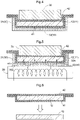
- the second precursor 12 is clamped by a mold 50 and then, as shown in Fig. 8 , the second precursor 12 will be heated while being compressed (pressing) by a press machine 60, whereby a compact 13 is obtained.
- the mold 50 includes a pair of upper mold 51 (an example of a "first mold") and a lower mold 52 (an example of a "second mold”).
- first mold an example of a "first mold”
- second mold an example of a "second mold”
- the pressure applied between the upper mold 51 and the lower mold 52 at the time of compression by the press machine 60 (this will be referred to as a "press pressure” hereinafter) will be set to a pressure from 1 MPa to 20 MPa, for example.
- This press pressure is typically from 3 MPa to 8 MPa.
- By increasing/decreasing the press pressure within an appropriate range (from 1 MPa to 20 MPa), it is possible to increase/decrease the density of the compact 13 to be obtained. For instance, if it is desired to increase the density of the compact 13, the press pressure will be increased. Conversely, if it is desired to decrease the density of the compact 13, the press pressure will be decreased.
- the upper mold 51 for instance, in its lower face, there are formed a recess portion 51a and a protruding portion 51b annularly surrounding the recess portion 51a.
- the lower mold 52 in its upper face, there are formed a protruding portion 52a to be fitted into the recess portion 51a and a recess portion 52b into which the protruding portion 51b will be fitted.
- the upper face of the lower mold 52 (the surface which comes into contact with the second precursor 12) is covered by a metal mesh 55 (an example of a "mesh-like member") formed to follow this upper face.
- the second precursor 12 will be molded into a shape that follows or complies with the shapes of the recess portion 51a and the protruding portion 51b of the upper mold 51 and the shapes of the protruding portion 52a and the recess portion 52b of the lower mold 52, thus being formed into the compact 13.
- the mold 50 will mold the second precursor 12 with heating this second precursor 12 by the heat supplied from the press machine 60.
- the mold 50 will mold the second precursor 12 with heating this second precursor 12 by the heat supplied from the press machine 60.
- the temperature used at the time of molding by the mold 50 is set to from 100°C to 150°C, for instance.
- an appropriate range e.g. the range from 100°C to 150°C
- adjustment is made possible to increase/decrease the tensile elasticity modulus or the bending elasticity modulus of the compact 13. If it is desired to increase the tensile elasticity modulus of the compact 13, the temperature at the time of molding by the mold 50 will be set to a higher temperature. Conversely, if it is desired to decrease the tensile elasticity modulus of the compact 13, the temperature at the time of molding by the mold 50 will be set to a lower temperature.
- the temperature of the upper mold 51 and the temperature of the lower mold 52 of the mold 50 may be set same as each other or may be set different from each other. Further alternatively, the temperature of the mold 50 may be changed in the course of molding.
- the metal mesh 55 is a mesh-like member formed with thin metal wires interwoven for instance.
- This metal mesh 55 may be a metal mesh woven by a certain standard weaving technique such as the plain weave or twill, etc. and a metal mesh from 100 mesh to 200 mesh number can be employed.
- the standard of the metal mesh 55 is explained herein based on JIS G 3555.
- the metal mesh 55 is used as a "slip stopper" for the second precursor 12 relative to the lower mold 52.
- This metal mesh 55 is interposed between the lower mold 52 and the second precursor 12, thanks to the frictional forces between the respective portions of the second precursor 12 and the metal mesh 55, break which can occur at the time of deformation of the second precursor 12 by the binding thereof between the upper mold 51 and the lower mold 52 (this will be referred to simply as “break phenomenon” hereinafter) is prevented.
- break phenomenon occurs due to occurrence of local deformation or displacement (distortion) at a part of the second precursor 12, in association with the binding thereof by the upper mold 51 and the lower mold 52.
- the press machine 60 is a device that compresses or presses the metal mesh 50.
- This press machine 60 includes a deck portion 66 on which the metal mesh 50, etc. is to be placed, a top plate 65 configured to bind the metal mesh 50 etc. with the deck portion 66, and pillar portions 69 incorporating hydraulic cylinders (not shown) for moving the top late 65 closer to or away from the deck portion 66.
- the press machine 60 is used in combination with spacers 61, 62 used at the time of pressing of the metal mesh 50 and heater blocks 63, 64 having heating elements such as sheath heaters, or the like. In the following, when it is referred to simply as the "press machine 60", this is understood to include such spacers 61, 62 and the heater blocks 63, 64.
- the temperatures of the heater blocks 63, 64 will be kept at predetermined temperatures by means of e.g. unillustrated temperature controller, or the like. Further, the pressing force applied to the top plate 65 by the pillar portions 69, i.e. the press pressure, will also be kept at a predetermined value by means of an unillustrated regulator.
- Fig. 8 illustrates a situation in which the mold 50 clamping the second precursor 12 is being compressed by the press machine 60, while it is being heated by the heater blocks 63, 64.
- the deck portion 66, the spacer 62, the heater block 64, the mold 50, the heater block 63, the spacer 61 and the top plate 65 are stuck one on another in this mentioned order; and under this condition, the top plate 65 is being pressed toward the deck portion 66 by means of the hydraulic cylinders of the pillar portions 69.
- the mold 50 is disposed between the heater block 64 and the heater block 63, with the second precursor 12 being bound between the upper mold 51 and the lower mold 52 thereof.
- the molding conditions (the temperature and the press pressure of the mold 50) used in the press machine 60 will be appropriately varied in accordance with the desired shape and/or the physical properties, etc. of the compact 13.
- the compressing of the mold 50 of the press machine 60 (the press molding of the second precursor 12) is effected in two separate steps, with conditions made different from each other.
- the temperature of the heater block 63 placed in contact with the upper mold 51 for enabling heat conduction therewith is set to 100°C
- the temperature of the heater block 64 placed in contact with the lower mold 52 for enabling heat conduction therewith is set to 150°C.
- the press pressure is progressively (e.g. proportionally) increased to a predetermined value (e.g. 8 MPa as the predetermined value).
- the temperature of the heater block 63 is changed to 150°C.
- the temperature of the heater block 64 and the press pressure are maintained same as those of the first step.
- the second step is completed to obtain the compact 13.
- the heating operations of the heater blocks 63, 64 are terminated and the press pressure of the top plate 65 is released.
- the mold 50 is removed from the press machine 60 and the compact 13 in the form of a thin plate molded to the desired shape will be collected (see Fig. 8 and Fig. 9 ).
- the compact 13 there are formed a first transferred portion 13a transferring the shapes of the recess portion 51a and the protruding portion 52a and a second transferred portion 13b transferring the shapes of the protruding portion 51b and the recess portion 52b, respectively.
- the compact 13 is molded into a desired shape as described above and moreover, the compact 13 will be formed as a cellulose thin plate (e.g. having a thickness of 200 pm) having a high strength ( 1.0 ⁇ 10 10 Pa) unobtainable by the conventional technique.
- This compact 13 can be used in an audio device such as a diaphragm of a speaker or other structure component. As the compact 13 has high internal loss, it can realize sound quality improvement for an audio component (especially, a speaker).
- structure component other than a speaker diaphragm is a home electric appliance or a car-mounted product and is suitable especially as a structure component of a car-mounted product from which weight reduction and strength are required.
- the manufacturing method of a cellulose nanofiber compact can realize a cellulose nanofiber compact having high strength.
- micro hollow glass spheres so-called glass bubbles
- cellulose spherical bodies carbon nanotubes
- weight reduction of the compact 13 can be achieved.
- carbon nanotubes further additional strength of the compact 13 as well as provision of electric conductivity thereto can be realized.
Landscapes
- Engineering & Computer Science (AREA)
- Manufacturing & Machinery (AREA)
- Paper (AREA)
- Polysaccharides And Polysaccharide Derivatives (AREA)
Claims (7)
- Verfahren zum Herstellen eines Zellulose-Nanofaser-Formkörpers (13), wobei das Verfahren umfasst:einen Kondensationsschritt zum Kondensieren einer Zellulose-Nanofasern enthaltenden Aufschlämmung, die Zellulose-Nanofasern in einer Menge enthält, die größer oder gleich 0,5 Masseprozent und kleiner oder gleich 10 Masseprozent ist, durch Mikrowellen-Erwärmen zum Erhalten eines plattenartigen ersten Vorprodukts (11), das eine Masse hat, die größer oder gleich 45% und kleiner oder gleich 55% relativ zu einer Masse der Aufschlämmung ist, wobei die Zellulose-Nanofaser einen Faserdurchmesser von größer oder gleich 1 nm und kleiner oder gleich 150 nm und eine Faserlänge von größer oder gleich 3 nm und kleiner oder gleich 300 µm hat;einen Abstützungsschritt zum Abstützen des ersten Vorprodukts (11) in einem Heizbehälter (30);einen vorläufigen Formungsschritt zum Erwärmen des ersten Vorprodukts (11), das in dem Heizbehälter (30) abgestützt wird, mit Infrarotstrahlung über einen Zeitraum von länger oder gleich 5 Minuten und kürzer oder gleich 15 Minuten und Beibehalten einer Temperatur des ersten Vorprodukts (11) bei größer oder gleich 45°C und kleiner oder gleich 115°C zum Erhalten eines plattenartigen zweiten Vorprodukts (12), das einen Wassergehalt hat, der geringer als ein Wassergehalt des ersten Vorprodukts (11) ist; undeinen Formungsschritt zum Formen des zweiten Vorprodukts (12) mit einem Erwärmen des zweiten Vorprodukts (12) und Unter-Druck-Setzen des zweiten Vorprodukts (12) mit einem Druck von größer oder gleich 1 MPa und kleiner oder gleich 20 MPa in einem Formwerkzeug (50), das eine Temperatur von größer oder gleich 100°C und kleiner oder gleich 150°C hat.
- Verfahren zum Herstellen eines Zellulose-Nanofaser-Formkörpers (13) gemäß Anspruch 1, wobei:der Heizbehälter (30) aus Keramik ausgebildet ist; undbei dem vorläufigen Erwärmungsschritt das erste Vorprodukt (11) durch Infrarotstrahlung erwärmt wird, die von dem Heizbehälter (30) abgestrahlt wird.
- Verfahren zum Herstellen eines Zellulose-Nanofaser-Formkörpers (13) gemäß Anspruch 1 oder 2, wobei:der Heizbehälter (30) aus einem porösen Körper besteht, der in sich viele Poren definiert, die ein Hindurchgelangen von Wasserdampf erlauben; undbei dem vorläufigen Erwärmungsschritt in dem ersten Vorprodukt (11) enthaltenes Wasser durch die Poren des Heizbehälters (30) nach außen entweicht.
- Verfahren zum Herstellen eines Zellulose-Nanofaser-Formkörpers (13) gemäß einem der Ansprüche 1 bis 3, wobei beim Abstützungsschritt das erste Vorprodukt (11) mit Zellophan (41) abgestützt wird, das zwischen dem ersten Vorprodukt (11) und dem Heizbehälter (30) angeordnet wird.
- Verfahren zum Herstellen eines Zellulose-Nanofaser-Formkörpers (13) gemäß einem der Ansprüche 1 bis 4, wobei:das Formwerkzeug (50) ein erstes Formwerkzeug (51) und ein zweites Formwerkzeug (52), das dem ersten Formwerkzeug (51) gegenüberliegt, aufweist;das zweite Vorprodukt (12) zwischen dem ersten Formwerkzeug (51) und dem zweiten Formwerkzeug (52) eingebracht und unter Druck gesetzt wird; undeine Oberfläche des zweiten Formwerkzeugs (52) in Kontakt mit dem zweiten Vorprodukt (12) durch ein maschenartiges Element (55) bedeckt ist.
- Verfahren zum Herstellen eines Zellulose-Nanofaser-Formkörpers (13) gemäß einem der Ansprüche 1 bis 5, wobei:
der Kondensationsschritt einen Ladeschritt zum Laden der Zellulose-Nanofasern enthaltenden Aufschlämmung in einen mit einem Boden versehenen zylindrischen Kondensationsbehälter (20) und einen Abdeckschritt zum Abdecken eines mittleren Teils der Oberfläche der Zellulose-Nanofasern enthaltenden Aufschlämmung in dem Kondensationsbehälter (20) mit einem Deckelelement (25) aufweist. - Verfahren zum Herstellen eines Zellulose-Nanofaser-Formkörpers (13) gemäß einem der Ansprüche 1 bis 6, wobei:
der vorläufige Formungsschritt einen Alterungsschritt zum Fördern der Wasserstoffbindung zwischen den Nanozellulose-Fasern in dem zweiten Vorprodukt (12) aufweist, während die Oberflächentemperatur des Heizbehälters (30) zwischen größer oder gleich 50°C und kleiner oder gleich 120°C gehalten wird.
Applications Claiming Priority (1)
| Application Number | Priority Date | Filing Date | Title |
|---|---|---|---|
| JP2019142746A JP7266489B2 (ja) | 2019-08-02 | 2019-08-02 | セルロースナノファイバー成形体の製造方法 |
Publications (2)
| Publication Number | Publication Date |
|---|---|
| EP3771773A1 EP3771773A1 (de) | 2021-02-03 |
| EP3771773B1 true EP3771773B1 (de) | 2023-01-11 |
Family
ID=71783852
Family Applications (1)
| Application Number | Title | Priority Date | Filing Date |
|---|---|---|---|
| EP20187312.2A Active EP3771773B1 (de) | 2019-08-02 | 2020-07-23 | Verfahren zur herstellung eines cellulosenanofaserpresslings |
Country Status (4)
| Country | Link |
|---|---|
| US (1) | US11525216B2 (de) |
| EP (1) | EP3771773B1 (de) |
| JP (1) | JP7266489B2 (de) |
| CN (1) | CN112301788A (de) |
Families Citing this family (2)
| Publication number | Priority date | Publication date | Assignee | Title |
|---|---|---|---|---|
| JP7780069B2 (ja) | 2021-02-19 | 2025-12-04 | 藤倉化成株式会社 | 防曇塗料 |
| EP4630624A1 (de) * | 2022-12-09 | 2025-10-15 | Lowd, Claudia | Vorrichtung und verfahren zur herstellung von geformten zellstoffprodukten aus nanocellulosefasern |
Family Cites Families (7)
| Publication number | Priority date | Publication date | Assignee | Title |
|---|---|---|---|---|
| JPH0643680B2 (ja) * | 1984-07-12 | 1994-06-08 | 敏 木村 | 単層繊維板の製造方法 |
| JPH01306700A (ja) * | 1988-05-30 | 1989-12-11 | Hitoshi Bito | 機能性パルプ材成型品の製造法 |
| JPH06248600A (ja) * | 1993-02-22 | 1994-09-06 | Noritake Co Ltd | パルプモールドの乾燥方法 |
| TW201525237A (zh) * | 2013-11-08 | 2015-07-01 | Dainippon Ink & Chemicals | 纖維素奈米纖維之製造方法、纖維素奈米纖維製造用紙漿、纖維素奈米纖維、樹脂組合物及成形體 |
| JP6460737B2 (ja) | 2014-11-14 | 2019-01-30 | 中越パルプ工業株式会社 | Cnfの成形方法及びその成形方法によって得られるcnf成形体 |
| JP6820711B2 (ja) | 2016-10-05 | 2021-01-27 | 大王製紙株式会社 | セルロースナノファイバー成形体の製造方法 |
| JP6756571B2 (ja) | 2016-10-13 | 2020-09-16 | 大王製紙株式会社 | セルロースナノファイバー成形体の製造方法 |
-
2019
- 2019-08-02 JP JP2019142746A patent/JP7266489B2/ja active Active
-
2020
- 2020-07-23 EP EP20187312.2A patent/EP3771773B1/de active Active
- 2020-07-29 US US16/941,660 patent/US11525216B2/en active Active
- 2020-07-31 CN CN202010757902.5A patent/CN112301788A/zh active Pending
Also Published As
| Publication number | Publication date |
|---|---|
| US11525216B2 (en) | 2022-12-13 |
| JP2021025146A (ja) | 2021-02-22 |
| CN112301788A (zh) | 2021-02-02 |
| US20210032816A1 (en) | 2021-02-04 |
| JP7266489B2 (ja) | 2023-04-28 |
| EP3771773A1 (de) | 2021-02-03 |
Similar Documents
| Publication | Publication Date | Title |
|---|---|---|
| US11525216B2 (en) | Method of manufacturing cellulose nanofiber compact | |
| TWI896789B (zh) | 一種在成型模具系統中對纖維素產品進行邊緣成型的方法,以及一種用於成型纖維素產品邊緣的成型模具系統 | |
| KR101608497B1 (ko) | 단열재 및 그 제조방법 | |
| CN116056857A (zh) | 多腔成型模具系统和用于在多腔成型模具系统中形成纤维素产品的方法 | |
| JP6460737B2 (ja) | Cnfの成形方法及びその成形方法によって得られるcnf成形体 | |
| JP5662078B2 (ja) | C/c複合材成形体及びその製造方法 | |
| JP2012528024A (ja) | 複合要素を製造するための装置および方法 | |
| US3354247A (en) | Method of producing porous separators | |
| US20200108352A1 (en) | Tunable graphene-based membranes and method of making the same | |
| US5238568A (en) | Porous carbon-carbon composite filtering membrane support with a carbon fibre mat substrate | |
| JP2002270191A (ja) | 炭素電極基材及びその製造方法 | |
| JP5398297B2 (ja) | 多孔質炭素電極基材の製造方法 | |
| JP2009280437A (ja) | 多孔質炭素シートの製造方法 | |
| CN107786934B (zh) | 应用含浆原布的喇叭振动片制造方法 | |
| US2619012A (en) | Method of making loud-speaker diaphragms | |
| JP2022088218A (ja) | セルロースナノファイバー含有成形体 | |
| JP2005104779A (ja) | 多孔質炭素板の製造方法 | |
| JP2007060628A (ja) | 音響振動板の製造方法、音響振動板、及びスピーカ | |
| JP2019509436A (ja) | 真空断熱パネルを製造する方法 | |
| TWI912893B (zh) | 二階段成型的喇叭振動片製造方法 | |
| US8955652B2 (en) | Apparatus and method of manufacturing brake lining | |
| JP2607397B2 (ja) | 多孔質ガラス状カーボン材の製造方法 | |
| JPH034508B2 (de) | ||
| JPS60148295A (ja) | スピ−カ紙製振動部品及びその製造方法 | |
| JP3651070B2 (ja) | 機械加工性に優れたガラス状カーボンの製造方法 |
Legal Events
| Date | Code | Title | Description |
|---|---|---|---|
| PUAI | Public reference made under article 153(3) epc to a published international application that has entered the european phase |
Free format text: ORIGINAL CODE: 0009012 |
|
| STAA | Information on the status of an ep patent application or granted ep patent |
Free format text: STATUS: THE APPLICATION HAS BEEN PUBLISHED |
|
| AK | Designated contracting states |
Kind code of ref document: A1 Designated state(s): AL AT BE BG CH CY CZ DE DK EE ES FI FR GB GR HR HU IE IS IT LI LT LU LV MC MK MT NL NO PL PT RO RS SE SI SK SM TR |
|
| AX | Request for extension of the european patent |
Extension state: BA ME |
|
| STAA | Information on the status of an ep patent application or granted ep patent |
Free format text: STATUS: REQUEST FOR EXAMINATION WAS MADE |
|
| 17P | Request for examination filed |
Effective date: 20210507 |
|
| RBV | Designated contracting states (corrected) |
Designated state(s): AL AT BE BG CH CY CZ DE DK EE ES FI FR GB GR HR HU IE IS IT LI LT LU LV MC MK MT NL NO PL PT RO RS SE SI SK SM TR |
|
| STAA | Information on the status of an ep patent application or granted ep patent |
Free format text: STATUS: EXAMINATION IS IN PROGRESS |
|
| 17Q | First examination report despatched |
Effective date: 20210723 |
|
| GRAP | Despatch of communication of intention to grant a patent |
Free format text: ORIGINAL CODE: EPIDOSNIGR1 |
|
| STAA | Information on the status of an ep patent application or granted ep patent |
Free format text: STATUS: GRANT OF PATENT IS INTENDED |
|
| INTG | Intention to grant announced |
Effective date: 20220816 |
|
| GRAS | Grant fee paid |
Free format text: ORIGINAL CODE: EPIDOSNIGR3 |
|
| GRAA | (expected) grant |
Free format text: ORIGINAL CODE: 0009210 |
|
| STAA | Information on the status of an ep patent application or granted ep patent |
Free format text: STATUS: THE PATENT HAS BEEN GRANTED |
|
| AK | Designated contracting states |
Kind code of ref document: B1 Designated state(s): AL AT BE BG CH CY CZ DE DK EE ES FI FR GB GR HR HU IE IS IT LI LT LU LV MC MK MT NL NO PL PT RO RS SE SI SK SM TR |
|
| REG | Reference to a national code |
Ref country code: GB Ref legal event code: FG4D |
|
| REG | Reference to a national code |
Ref country code: CH Ref legal event code: EP |
|
| REG | Reference to a national code |
Ref country code: DE Ref legal event code: R096 Ref document number: 602020007492 Country of ref document: DE |
|
| REG | Reference to a national code |
Ref country code: IE Ref legal event code: FG4D |
|
| REG | Reference to a national code |
Ref country code: AT Ref legal event code: REF Ref document number: 1543480 Country of ref document: AT Kind code of ref document: T Effective date: 20230215 |
|
| REG | Reference to a national code |
Ref country code: LT Ref legal event code: MG9D |
|
| REG | Reference to a national code |
Ref country code: NL Ref legal event code: MP Effective date: 20230111 |
|
| REG | Reference to a national code |
Ref country code: AT Ref legal event code: MK05 Ref document number: 1543480 Country of ref document: AT Kind code of ref document: T Effective date: 20230111 |
|
| PG25 | Lapsed in a contracting state [announced via postgrant information from national office to epo] |
Ref country code: NL Free format text: LAPSE BECAUSE OF FAILURE TO SUBMIT A TRANSLATION OF THE DESCRIPTION OR TO PAY THE FEE WITHIN THE PRESCRIBED TIME-LIMIT Effective date: 20230111 |
|
| PG25 | Lapsed in a contracting state [announced via postgrant information from national office to epo] |
Ref country code: RS Free format text: LAPSE BECAUSE OF FAILURE TO SUBMIT A TRANSLATION OF THE DESCRIPTION OR TO PAY THE FEE WITHIN THE PRESCRIBED TIME-LIMIT Effective date: 20230111 Ref country code: PT Free format text: LAPSE BECAUSE OF FAILURE TO SUBMIT A TRANSLATION OF THE DESCRIPTION OR TO PAY THE FEE WITHIN THE PRESCRIBED TIME-LIMIT Effective date: 20230511 Ref country code: NO Free format text: LAPSE BECAUSE OF FAILURE TO SUBMIT A TRANSLATION OF THE DESCRIPTION OR TO PAY THE FEE WITHIN THE PRESCRIBED TIME-LIMIT Effective date: 20230411 Ref country code: LV Free format text: LAPSE BECAUSE OF FAILURE TO SUBMIT A TRANSLATION OF THE DESCRIPTION OR TO PAY THE FEE WITHIN THE PRESCRIBED TIME-LIMIT Effective date: 20230111 Ref country code: LT Free format text: LAPSE BECAUSE OF FAILURE TO SUBMIT A TRANSLATION OF THE DESCRIPTION OR TO PAY THE FEE WITHIN THE PRESCRIBED TIME-LIMIT Effective date: 20230111 Ref country code: HR Free format text: LAPSE BECAUSE OF FAILURE TO SUBMIT A TRANSLATION OF THE DESCRIPTION OR TO PAY THE FEE WITHIN THE PRESCRIBED TIME-LIMIT Effective date: 20230111 Ref country code: ES Free format text: LAPSE BECAUSE OF FAILURE TO SUBMIT A TRANSLATION OF THE DESCRIPTION OR TO PAY THE FEE WITHIN THE PRESCRIBED TIME-LIMIT Effective date: 20230111 Ref country code: AT Free format text: LAPSE BECAUSE OF FAILURE TO SUBMIT A TRANSLATION OF THE DESCRIPTION OR TO PAY THE FEE WITHIN THE PRESCRIBED TIME-LIMIT Effective date: 20230111 |
|
| PG25 | Lapsed in a contracting state [announced via postgrant information from national office to epo] |
Ref country code: SE Free format text: LAPSE BECAUSE OF FAILURE TO SUBMIT A TRANSLATION OF THE DESCRIPTION OR TO PAY THE FEE WITHIN THE PRESCRIBED TIME-LIMIT Effective date: 20230111 Ref country code: PL Free format text: LAPSE BECAUSE OF FAILURE TO SUBMIT A TRANSLATION OF THE DESCRIPTION OR TO PAY THE FEE WITHIN THE PRESCRIBED TIME-LIMIT Effective date: 20230111 Ref country code: IS Free format text: LAPSE BECAUSE OF FAILURE TO SUBMIT A TRANSLATION OF THE DESCRIPTION OR TO PAY THE FEE WITHIN THE PRESCRIBED TIME-LIMIT Effective date: 20230511 Ref country code: GR Free format text: LAPSE BECAUSE OF FAILURE TO SUBMIT A TRANSLATION OF THE DESCRIPTION OR TO PAY THE FEE WITHIN THE PRESCRIBED TIME-LIMIT Effective date: 20230412 Ref country code: FI Free format text: LAPSE BECAUSE OF FAILURE TO SUBMIT A TRANSLATION OF THE DESCRIPTION OR TO PAY THE FEE WITHIN THE PRESCRIBED TIME-LIMIT Effective date: 20230111 |
|
| REG | Reference to a national code |
Ref country code: DE Ref legal event code: R097 Ref document number: 602020007492 Country of ref document: DE |
|
| PG25 | Lapsed in a contracting state [announced via postgrant information from national office to epo] |
Ref country code: SM Free format text: LAPSE BECAUSE OF FAILURE TO SUBMIT A TRANSLATION OF THE DESCRIPTION OR TO PAY THE FEE WITHIN THE PRESCRIBED TIME-LIMIT Effective date: 20230111 Ref country code: RO Free format text: LAPSE BECAUSE OF FAILURE TO SUBMIT A TRANSLATION OF THE DESCRIPTION OR TO PAY THE FEE WITHIN THE PRESCRIBED TIME-LIMIT Effective date: 20230111 Ref country code: EE Free format text: LAPSE BECAUSE OF FAILURE TO SUBMIT A TRANSLATION OF THE DESCRIPTION OR TO PAY THE FEE WITHIN THE PRESCRIBED TIME-LIMIT Effective date: 20230111 Ref country code: DK Free format text: LAPSE BECAUSE OF FAILURE TO SUBMIT A TRANSLATION OF THE DESCRIPTION OR TO PAY THE FEE WITHIN THE PRESCRIBED TIME-LIMIT Effective date: 20230111 Ref country code: CZ Free format text: LAPSE BECAUSE OF FAILURE TO SUBMIT A TRANSLATION OF THE DESCRIPTION OR TO PAY THE FEE WITHIN THE PRESCRIBED TIME-LIMIT Effective date: 20230111 |
|
| PLBE | No opposition filed within time limit |
Free format text: ORIGINAL CODE: 0009261 |
|
| STAA | Information on the status of an ep patent application or granted ep patent |
Free format text: STATUS: NO OPPOSITION FILED WITHIN TIME LIMIT |
|
| PG25 | Lapsed in a contracting state [announced via postgrant information from national office to epo] |
Ref country code: SK Free format text: LAPSE BECAUSE OF FAILURE TO SUBMIT A TRANSLATION OF THE DESCRIPTION OR TO PAY THE FEE WITHIN THE PRESCRIBED TIME-LIMIT Effective date: 20230111 |
|
| PGFP | Annual fee paid to national office [announced via postgrant information from national office to epo] |
Ref country code: FR Payment date: 20230724 Year of fee payment: 4 Ref country code: DE Payment date: 20230628 Year of fee payment: 4 |
|
| 26N | No opposition filed |
Effective date: 20231012 |
|
| PG25 | Lapsed in a contracting state [announced via postgrant information from national office to epo] |
Ref country code: SI Free format text: LAPSE BECAUSE OF FAILURE TO SUBMIT A TRANSLATION OF THE DESCRIPTION OR TO PAY THE FEE WITHIN THE PRESCRIBED TIME-LIMIT Effective date: 20230111 |
|
| PG25 | Lapsed in a contracting state [announced via postgrant information from national office to epo] |
Ref country code: MC Free format text: LAPSE BECAUSE OF FAILURE TO SUBMIT A TRANSLATION OF THE DESCRIPTION OR TO PAY THE FEE WITHIN THE PRESCRIBED TIME-LIMIT Effective date: 20230111 |
|
| PG25 | Lapsed in a contracting state [announced via postgrant information from national office to epo] |
Ref country code: MC Free format text: LAPSE BECAUSE OF FAILURE TO SUBMIT A TRANSLATION OF THE DESCRIPTION OR TO PAY THE FEE WITHIN THE PRESCRIBED TIME-LIMIT Effective date: 20230111 |
|
| REG | Reference to a national code |
Ref country code: CH Ref legal event code: PL |
|
| REG | Reference to a national code |
Ref country code: BE Ref legal event code: MM Effective date: 20230731 |
|
| PG25 | Lapsed in a contracting state [announced via postgrant information from national office to epo] |
Ref country code: LU Free format text: LAPSE BECAUSE OF NON-PAYMENT OF DUE FEES Effective date: 20230723 |
|
| PG25 | Lapsed in a contracting state [announced via postgrant information from national office to epo] |
Ref country code: LU Free format text: LAPSE BECAUSE OF NON-PAYMENT OF DUE FEES Effective date: 20230723 |
|
| REG | Reference to a national code |
Ref country code: IE Ref legal event code: MM4A |
|
| PG25 | Lapsed in a contracting state [announced via postgrant information from national office to epo] |
Ref country code: CH Free format text: LAPSE BECAUSE OF NON-PAYMENT OF DUE FEES Effective date: 20230731 |
|
| PG25 | Lapsed in a contracting state [announced via postgrant information from national office to epo] |
Ref country code: IT Free format text: LAPSE BECAUSE OF FAILURE TO SUBMIT A TRANSLATION OF THE DESCRIPTION OR TO PAY THE FEE WITHIN THE PRESCRIBED TIME-LIMIT Effective date: 20230111 Ref country code: BE Free format text: LAPSE BECAUSE OF NON-PAYMENT OF DUE FEES Effective date: 20230731 |
|
| PG25 | Lapsed in a contracting state [announced via postgrant information from national office to epo] |
Ref country code: IE Free format text: LAPSE BECAUSE OF NON-PAYMENT OF DUE FEES Effective date: 20230723 |
|
| PG25 | Lapsed in a contracting state [announced via postgrant information from national office to epo] |
Ref country code: IE Free format text: LAPSE BECAUSE OF NON-PAYMENT OF DUE FEES Effective date: 20230723 |
|
| PG25 | Lapsed in a contracting state [announced via postgrant information from national office to epo] |
Ref country code: BG Free format text: LAPSE BECAUSE OF FAILURE TO SUBMIT A TRANSLATION OF THE DESCRIPTION OR TO PAY THE FEE WITHIN THE PRESCRIBED TIME-LIMIT Effective date: 20230111 |
|
| PG25 | Lapsed in a contracting state [announced via postgrant information from national office to epo] |
Ref country code: BG Free format text: LAPSE BECAUSE OF FAILURE TO SUBMIT A TRANSLATION OF THE DESCRIPTION OR TO PAY THE FEE WITHIN THE PRESCRIBED TIME-LIMIT Effective date: 20230111 |
|
| REG | Reference to a national code |
Ref country code: DE Ref legal event code: R119 Ref document number: 602020007492 Country of ref document: DE |
|
| GBPC | Gb: european patent ceased through non-payment of renewal fee |
Effective date: 20240723 |
|
| PG25 | Lapsed in a contracting state [announced via postgrant information from national office to epo] |
Ref country code: DE Free format text: LAPSE BECAUSE OF NON-PAYMENT OF DUE FEES Effective date: 20250201 |
|
| PG25 | Lapsed in a contracting state [announced via postgrant information from national office to epo] |
Ref country code: FR Free format text: LAPSE BECAUSE OF NON-PAYMENT OF DUE FEES Effective date: 20240731 |
|
| PG25 | Lapsed in a contracting state [announced via postgrant information from national office to epo] |
Ref country code: GB Free format text: LAPSE BECAUSE OF NON-PAYMENT OF DUE FEES Effective date: 20240723 |
|
| PG25 | Lapsed in a contracting state [announced via postgrant information from national office to epo] |
Ref country code: CY Free format text: LAPSE BECAUSE OF FAILURE TO SUBMIT A TRANSLATION OF THE DESCRIPTION OR TO PAY THE FEE WITHIN THE PRESCRIBED TIME-LIMIT; INVALID AB INITIO Effective date: 20200723 |
|
| PG25 | Lapsed in a contracting state [announced via postgrant information from national office to epo] |
Ref country code: HU Free format text: LAPSE BECAUSE OF FAILURE TO SUBMIT A TRANSLATION OF THE DESCRIPTION OR TO PAY THE FEE WITHIN THE PRESCRIBED TIME-LIMIT; INVALID AB INITIO Effective date: 20200723 |
|
| PG25 | Lapsed in a contracting state [announced via postgrant information from national office to epo] |
Ref country code: TR Free format text: LAPSE BECAUSE OF FAILURE TO SUBMIT A TRANSLATION OF THE DESCRIPTION OR TO PAY THE FEE WITHIN THE PRESCRIBED TIME-LIMIT Effective date: 20230111 |