EP3771387B1 - Antriebsvorrichtung für eine küchenmaschine - Google Patents
Antriebsvorrichtung für eine küchenmaschine Download PDFInfo
- Publication number
- EP3771387B1 EP3771387B1 EP20183660.8A EP20183660A EP3771387B1 EP 3771387 B1 EP3771387 B1 EP 3771387B1 EP 20183660 A EP20183660 A EP 20183660A EP 3771387 B1 EP3771387 B1 EP 3771387B1
- Authority
- EP
- European Patent Office
- Prior art keywords
- toothed belt
- planetary gear
- drive device
- gear system
- output shaft
- Prior art date
- Legal status (The legal status is an assumption and is not a legal conclusion. Google has not performed a legal analysis and makes no representation as to the accuracy of the status listed.)
- Active
Links
Images


Classifications
-
- A—HUMAN NECESSITIES
- A47—FURNITURE; DOMESTIC ARTICLES OR APPLIANCES; COFFEE MILLS; SPICE MILLS; SUCTION CLEANERS IN GENERAL
- A47J—KITCHEN EQUIPMENT; COFFEE MILLS; SPICE MILLS; APPARATUS FOR MAKING BEVERAGES
- A47J43/00—Implements for preparing or holding food, not provided for in other groups of this subclass
- A47J43/04—Machines for domestic use not covered elsewhere, e.g. for grinding, mixing, stirring, kneading, emulsifying, whipping or beating foodstuffs, e.g. power-driven
- A47J43/07—Parts or details, e.g. mixing tools, whipping tools
- A47J43/08—Driving mechanisms
- A47J43/085—Driving mechanisms for machines with tools driven from the lower side
-
- F—MECHANICAL ENGINEERING; LIGHTING; HEATING; WEAPONS; BLASTING
- F16—ENGINEERING ELEMENTS AND UNITS; GENERAL MEASURES FOR PRODUCING AND MAINTAINING EFFECTIVE FUNCTIONING OF MACHINES OR INSTALLATIONS; THERMAL INSULATION IN GENERAL
- F16H—GEARING
- F16H7/00—Gearings for conveying rotary motion by endless flexible members
- F16H7/08—Means for varying tension of belts, ropes or chains
- F16H7/10—Means for varying tension of belts, ropes or chains by adjusting the axis of a pulley
Definitions
- the invention relates to a drive device for a food processor, comprising an electric motor and a planetary gear, preferably with belt drive.
- a large proportion of the noise is generated by the grinding noise when chopping. However, a not insignificant proportion of the noise is also generated by the drive, the gear and the dissipation of the motor vibrations into the housing. The resulting noise is evident when stirring, when the food being cooked in the food processor usually does not make any noise.
- metal gears In order to transmit high torques for kneading and crushing to the agitator, metal gears are generally used that can transmit the required torques. To save costs, gears with non-involute spur gears are often used.
- the US patent US 4 600 155 A discloses a machine for processing foodstuffs comprising a container, the position of which on a support base is determined by a finger projecting from the container which engages in a recess in the support base.
- the base is part of a housing in which a drive motor is arranged which drives a shaft projecting vertically into the container and carries corresponding knives.
- the container is covered by a removable cover and locks are provided to prevent the drive motor from being started if the container is not correctly positioned, the removable cover being locked over the container and suitably positioned relative to the container.
- a multi-purpose kitchen appliance which consists of an electric motor, via whose drive shaft two output shafts mounted on an axis and rotating at different speeds are driven. Both the drive shaft and both output shafts have corresponding pulleys, each of which is connected by a belt.
- the belt tension between the drive shaft and the first output shaft is achieved by a relative parallel displacement between the drive shaft and the common axis and the subsequent fixing in the position that provides the necessary belt tension.
- the belt tension between the drive shaft and the second output shaft is achieved by a belt tensioner that deflects the guide of the second belt.
- the US patent US 4 113 188 A discloses a food processor including a housing having a motor chamber disposed adjacent to a food processing bowl, thereby significantly reducing the overall height of the appliance.
- a lid is removably attached to the bowl and, when properly positioned, actuates a motor control switch on the housing, allowing the motor to rotate an implement disposed in the bowl.
- the object of the invention is therefore to provide an improved drive device for a food processor, in particular a drive device which is cost-effective, quieter than prior art food processors and which nevertheless delivers a high torque.
- a multi-part drive device for a food processor has a motor with a vertical drive shaft/vertical motor shaft that stands upright next to the cooking, kneading or stirring bowl. This transmits its torque to the stirring shaft of the food processor via a planetary gear and a toothed belt drive.
- the rotor of the electric motor extends over the motor shaft into the planetary gear.
- An assembly carriage serves as the foundation for the electrically operated motor and the planetary gear.
- the arrangement is placed on a base plate, with the assembly carriage being arranged on the base plate so that it can be moved and fixed.
- the purpose of the movable arrangement is to ensure that the toothed belt can be optimally tensioned.
- a toothed belt that is too tightly tensioned tends to increase losses and thus also generates a lot of noise.
- An optimally tensioned toothed belt on the other hand, can transmit torque from one toothed belt pulley to the next with little noise.
- the output shaft of the planetary gear extends to below the base plate and has a first toothed belt pulley there.
- this output shaft of the planetary gear there is an output shaft with a coupling for a stirrer that is remote from the position of the assembly slide.
- This remote output shaft is arranged parallel to the rotation axis of the electric motor, and the remote output shaft has a second toothed belt pulley.
- This second toothed belt pulley is arranged in the same plane as the first toothed belt pulley of the output shaft of the planetary gear, and both toothed belt pulleys are connected to one another via a toothed belt.
- the design with a planetary gear directly connected to the motor shaft and a toothed belt pulley that is connected to the output shaft for the agitator via a toothed belt enables low-noise operation while maintaining high torque.
- the assembly carriage can be arranged so that it can be moved in the direction of the connecting axis between the two toothed belt pulleys.
- the assembly carriage can be moved within the limits of elongated holes in the base plate using a clamping screw for fixing, with the clamping screw moving the assembly carriage in the direction along the connecting axis between the two toothed belt pulleys.
- the planetary gear is firmly connected to the assembly carriage via a flange (on the gear housing), with the electrically operated motor being positioned on the top of the gear housing, which is positioned opposite the assembly carriage.
- the assembly carriage thus serves as a foundation for the motor and the planetary gear, both of which can be pre-assembled and can be easily connected to one another to unite the motor and gear unit with the base plate.
- the shaft of the electric motor extends into the planetary gear and, as the sun gear of the planetary gear, has a helical toothing and meshes with the planetary gears of the planetary gear.
- the shaft of the motor is therefore also a driving gear and is made of metal.
- the gears of the planetary gear can also be made of plastic. The interlocking of metal and plastic prevents high levels of noise.
- the two toothed belt pulleys have the same diameter and that the two toothed belt pulleys connected via the toothed belt have a transmission ratio of one during operation.
- the two toothed belt pulleys are therefore the same size and the opposing belt segments of the forward belt part and the return belt part run parallel to one another.
- the following procedure can be provided for simple assembly of the drive device for a food processor: First, a base plate equipped with the removed output shaft, which is already equipped with the second toothed belt pulley, is positioned in a holding device of an assembly device. Then an electrically operated motor, the shaft of which with helical gearing extends into a planetary gear as a sun gear, and the planetary gear is fastened to a mounting carriage with a flange, is inserted into a recess in the base plate, with a first toothed belt pulley mounted on the output shaft of the planetary gear protruding below the base plate.
- This assembly is then further assembled as follows:
- the motor together with the gear is preferably moved in the direction of the connecting axis; because ribs are integrated into the cover of the planetary gear and corresponding ribs are provided on the base plate, there is an overlap between the ribs on the base plate and the ribs on the cover, so that the assembly is clearly limited in the direction of the axis of rotation.
- This is followed by inserting a timing belt over the two timing belt pulleys, tightening a tensioning screw, which removes the assembly carriage from the removed output shaft until the timing belt is tensioned.
- the tensioning screw is then tightened, which is completed at the time when the timing belt when a lateral force of 2 N to 3 N is applied between the two timing belt pulleys, the belt will give way by 2 mm to 8 mm.
- the timing belt tension can be measured using a spring scale or a push rod with a force sensor. For a very precise pre-tension, the timing belt tension can be adjusted by tightening so that at 2.5 N the timing belt gives way by 4 mm.
- the timing belt After the timing belt is tensioned, it is advantageous to check and fix the position of the assembly slide not only by the tensioning screw, but by subsequently fixing the assembly slide by tightening at least two fixing screws in the elongated holes that extend into the base plate.
- the tension of the tensioning screw and the fixing screws can finally be secured using screw or thread lock.
- the drive device can be one of the main sources of vibrations in a food processor.
- the drive device according to the invention has a buffer, e.g. a buffer with an H-shaped cross section, which isolates the drive device from the housing of the food processor.
- the buffer is preferably made of polyurethane or comprises polyurethane. It is an achievable advantage of the polyurethane material, especially in comparison to other materials such as EPDM, that the housing reacts less strongly to vibrations of the drive. One reason for this can be the particular density of the polyurethane material in comparison to EPDM.
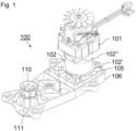
- FIG 1 is a sketch of the drive device 100 according to the invention for a food processor in a perspective view.
- This drive device 100 has an electric motor 101 and a planetary gear 102, whereby the rotor 103 of the electric motor 101, which is not visible in this figure, extends over the motor shaft 104 into the planetary gear 102.
- the electric motor 101 and the planetary gear 102 are directly connected to one another and mounted on an assembly carriage 105, which serves as a foundation for the electrically operated motor (101) and the planetary gear (102).
- the individual unit of motor 101, planetary gear 102 and assembly carriage 105 are in Figure 2 explained in more detail.
- this unit is mounted on a base plate 106, beneath which there are further elements.
- the assembly carriage 105 is arranged on the base plate 106 so that it can be moved and fixed. The moveability makes it possible to tension the toothed belt underneath the base plate.
- an output shaft 109 with coupling 110 for an agitator is present, which is located away from the position of the assembly slide 105.
- the remote output shaft 109 is parallel to the rotation axis U (see Figure 3 ) of the electric motor 101.
- the remote output shaft 109) has a second toothed belt pulley 111, which is arranged in the same plane as the first toothed belt pulley 108 of the output shaft 107 of the planetary gear, which is hidden here and is also arranged below the base plate.
- the isolated unit consisting of electric motor 101, planetary gear 102 and mounting plate 105 is shown in the following figure, Figure 2 shown.
- FIG 2 it is shown how the electric motor 101 sits on the gear housing 102" of the planetary gear 102.
- the planetary gear 102 is in turn firmly screwed to the base plate 106 via a flange 102', so that the base plate 106 is firmly connected to the planetary gear housing 102".
- These three elements, namely the electric motor 101, the planetary gear 102 and the assembly carriage can be pre-assembled as a single unit elsewhere and this unit can be installed as a whole in the assembly process.
- FIG. 3 a vertical section through the drive device 100 according to the invention for a food processor is shown.
- the shaft 101' In the middle of the electric motor 101 is the shaft 101', which passes over the motor shaft 104, which projects into the planetary gear 102 as a sun gear with helical teeth.
- the output shaft 107 of the planetary gear 102 is in turn directly connected to a toothed belt pulley 108, which drives a remote toothed belt pulley 111 via a toothed belt 112.
- the torque of the toothed belt pulley 111 is in turn transmitted to the output shaft 109, which has a coupling 110 for a stirrer or grinder at the upper end.
- a buffer 122 is also shown, which is round in plan view and H-shaped in cross section.
- the buffer is made of polyurethane and serves to isolate the drive device from vibrations in relation to the food processor housing.
- the unit is made of Figure 2 together with the mounting carriage 105 is placed on the base plate 106 and retracted by means of the tensioning screw 113, whereby the toothed belt 112 is tensioned, which encloses the toothed belt pulley 108 and also the toothed belt pulley 111.
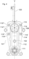
- FIG 4 a view of the underside of the base plate 106 with the toothed belt mounted and the unit consisting of the electric motor 101, planetary gear 102 and toothed belt pulley 108 is shown.
- the toothed belt pulley 108 which is connected to the planetary gear 102, protrudes through a recess in the base plate 106 and is enclosed by a toothed belt 112.
- a tensioning screw 113 (visible in Figure 3 ) is rotated with the aid of a tool 120 so that the assembly carriage 105 is displaced within the boundaries of the elongated holes 114, 114', 114"* and 114′′′ along the connecting axis V between the two toothed belt pulleys 108 and 11, whereby the toothed belt 112 is tensioned.
- the tension of the toothed belt 112 is checked during installation by a push rod 121.
- the tension screw 113 is tightened until the tension of the toothed belt 112 allows the push rod 121 to move approximately 4 mm when the push rod 121 presses laterally onto the tensioned toothed belt 112 with a force of 2.5 N.
- the drive device is cost-effective, quieter than state-of-the-art kitchen machines and still delivers high torque.
Landscapes
- Engineering & Computer Science (AREA)
- General Engineering & Computer Science (AREA)
- Mechanical Engineering (AREA)
- Food Science & Technology (AREA)
- Food-Manufacturing Devices (AREA)
- Transmission Devices (AREA)
Description
- Die Erfindung betrifft Antriebsvorrichtung für eine Küchenmaschine, aufweisend einen elektrischen Motor, und ein Planetengetriebe, vorzugsweise mit Riemenantrieb.
- Der Betrieb von Küchenmaschinen mit einem Rühr- und Zerkleinerungswerk ist häufig mit einer nicht unerheblichen Geräuschentwicklung verbunden, wobei der Lärmpegel eine für den privaten Haushalt unzumutbare Höhe annehmen kann.
- Ein großer Anteil wird beim Zerkleinern durch das Mahlgeräusch erzeugt. Ein nicht unerheblicher Anteil des Lärms wird aber auch durch den Antrieb, das Getriebe und die Ableitung der Motorvibrationen in das Gehäuse erzeugt. Der hierdurch entstehende Geräuschanteil zeigt sich beim Rühren, bei dem das Kochgut in der Küchenmaschine in der Regel keine Geräusche erzeugt.
- Um hohe Drehmomente zum Kneten und zum Zerkleinern an das Rührwerk weiterzuleiten, werden in der Regel metallische Getriebe eingesetzt, welche die erforderlichen Drehmomente übertragen können. Um Kosten zu sparen, wird dabei häufig auf Getriebe mit nicht evolventenverzahnten Stirnrädern zurückgegriffen.
- Um die Geräuschentwicklung zu minimieren, werden häufig solche Antriebsmotoren eingesetzt, deren Drehmoment gerade eben ausreicht, um das erforderliche Drehmoment zum Rühren und zum Zerkleinern mit hoher Umdrehungszahl zu erreichen. Um die hohe Drehzahl zu erreichen, ohne dabei ein Übermaß an Vibrationen in das Gehäuse der Küchenmaschine abzuleiten, wird auch auf direktantriebe ohne Getriebe zurückgegriffen. Es besteht ein Kompromiss zwischen Kosten, Laustärkeentwicklung und Drehmoment. Ein idealer Antrieb ist kostengünstig, leise und drehmomentstark.
- Die US-Patentschrift
US 4 600 155 A offenbart eine Maschine zur Verarbeitung von Lebensmitteln mit einem Behälter, dessen Position auf einem Trägersockel durch einen aus dem Behälter herausragenden Finger bestimmt wird, der in eine Aufnahme im Trägersockel eingreift. Der Sockel ist Teil eines Gehäuses, in dem ein Antriebsmotor angeordnet ist, der eine vertikal in den Behälter ragende Welle antreibt und entsprechende Messer trägt. Der Behälter ist durch eine abnehmbare Abdeckung abgedeckt und es sind Verriegelungen vorgesehen um zu verhindern, dass der Antriebsmotor gestartet wird, wenn der Behälter nicht korrekt positioniert ist, die abnehmbare Abdeckung über dem Behälter verriegelt und in geeigneter Weise relativ zum Behälter positioniert ist. - Aus der
EP 0 570 685 A1 ist eine Vielzweckküchenmaschine bekannt, die aus einem Elektromotor, über dessen Antriebswelle zwei in einer Achse gelagerte und mit unterschiedlichen Drehzahlen sich drehende Abtriebswellen angetrieben werden, besteht. Sowohl die Antriebswelle als auch beide Abtriebswellen weisen entsprechende Riemenscheiben auf, die über je einen Riemen in Drehverbindung stehen. Die Riemenspannung zwischen der Antriebswelle und der ersten Abtriebswelle erfolgt durch eine relative Parallelverschiebung zwischen der Antriebswelle und der gemeinsamen Achse und der anschließenden Fixierung in der die notwendige Riemenspannung abgebenden Lage. Dabei erfolgt die Riemenspannung zwischen der Antriebswelle und der zweiten Abtriebswelle durch einen die Führung des zweiten Riemens umlenkenden Riemenspanner. - Die US-Patentschrift
US 4 113 188 A offenbart eine Küchenmaschine enthaltend ein Gehäuse mit einer Motorkammer, die neben einer Lebensmittelverarbeitungsschüssel angeordnet ist, wodurch die Gesamthöhe des Geräts erheblich verringert wird. Ein Deckel ist abnehmbar an der Schüssel befestigt und betätigt bei richtiger Position einen Motorsteuerschalter am Gehäuse, wodurch der Motor ein in der Schüssel angeordnetes Werkzeug drehen kann. - Aufgabe der Erfindung ist es daher, eine verbesserte Antriebseinrichtung für eine Küchenmaschine zur Verfügung zu stellen, insbesondere eine Antriebsvorrichtung, die kostengünstig ist, leiser ist als Küchenmaschinen aus dem Stand der Technik und die dennoch ein hohes Drehmoment liefert.
- Die Bezugszeichen in sämtlichen Ansprüchen haben keine einschränkende Wirkung, sondern sollen lediglich deren Lesbarkeit verbessern.
- Die erfindungsgemäße Aufgabe wird dadurch gelöst durch eine Antriebsvorrichtung für eine Küchenmaschine mit den Merkmalen nach Anspruch 1. Vorteilhafte Aus- und Weiterbildungen, welche einzeln oder in Kombination miteinander eingesetzt werden können, sind Gegenstand der abhängigen Ansprüche und der nachfolgenden Beschreibung.
- Nach dem Gedanken der Erfindung ist eine mehrteilige Antriebsvorrichtung vorgesehen. Diese Antriebsvorrichtung für eine Küchenmaschine weist einen neben dem Koch-, Knet- oder Rührtopf aufrechtstehenden Motor mit vertikaler Antriebswelle / vertikalem Motorschaft auf. Dieser leitet sein Drehmoment in die Rührwelle der Küchenmaschine über ein Planetengetriebe und einen Zahnriementrieb. Dabei ist vorgesehen, dass der Rotor des elektrischen Motors über den Motorschaft in das Planetengetriebe reicht. Ein Montageschlitten dient als Fundament für den elektrisch betriebenen Motor und das Planetengetriebe. Die Anordnung ist platziert auf einer eine Grundplatte, wobei der Montageschlitten auf der Grundplatte verschieblich und fixierbar angeordnet ist. Die verschiebliche Anordnung hat zum Zweck, dass der Zahnriemen optimal gespannt werden kann. Ein Zahnriemen, der zu stark gespannt ist, neigt zu vergrößerten Verlusten und erzeugt somit auch eine starke Geräuschentwicklung. Ein optimal gespannter Zahnriemen kann hingegen geräuscharm Drehmoment von einer Zahnriemenscheibe zur nächsten weiterleiten.
- In der Antriebsvorrichtung für eine Küchenmaschine ist des Weiteren vorgesehen, dass die Abtriebswelle des Planetengetriebes bis unterhalb der Grundplatte reicht und dort eine erste Zahnriemenscheibe aufweist. Neben dieser Abtriebswelle des Planetengetriebes ist eine von der Position des Montageschlittens entfernte Abtriebswelle mit Kupplung für ein Rührwerk vorhanden. Diese entfernte Abtriebswelle ist parallel zur Umdrehungsachse des elektrischen Motors angeordnet ist, und die entfernte Abtriebswelle weist eine zweite Zahnriemenscheibe auf. Diese zweite Zahnriemenscheibe ist in der gleichen Ebene angeordnet, wie die erste Zahnriemenscheibe der Abtriebswelle des Planetengetriebes und beide Zahnriemenscheiben sind über einen Zahnriemen miteinander verbunden.
- Vorteilhafte Aus- und Weiterbildungen, welche einzeln oder in Kombination miteinander eingesetzt werden können, sind Gegenstand der abhängigen Ansprüche und der nachfolgenden Beschreibung.
- Der Aufbau mit unmittelbar am Motorschaft angebundenem Planetengetriebe und mit Zahnriemenscheibe, die über einen Zahnriemen mit der Abtriebswelle für das Rührwerk verbunden ist, ermöglicht einen geräuscharmen Lauf bei gleichzeitig hohem Drehmoment.
- Zum leichten Spannen des Zahnriemens kann vorgesehen sein, dass der Montageschlitten in Richtung der Verbindungsachse zwischen den beiden Zahnriemenscheiben verschieblich angeordnet ist. Dabei kann der Montageschlitten über eine Spannschraube innerhalb der Grenzen von Langlöchern in der Grundplatte zum Fixieren verschiebbar sein, wobei die Spannschraube den Montageschlitten in Richtung entlang der Verbindungsachse zwischen den beiden Zahnriemenscheiben verschiebt.
- In Ausgestaltung der erfindungsgemäßen Antriebsvorrichtung für eine Küchenmaschine kann vorgesehen sein, dass das Planetengetriebe über einen Flansch (am Getriebegehäuse fest mit dem Montageschlitten verbunden ist, wobei auf der Oberseite des Getriebegehäuses, die dem Montageschlitten gegenüber positioniert ist, der elektrisch betriebene Motor positioniert ist. Der Montageschlitten dient somit als Fundament für den Motor und das Planetengetriebe, die beide vormontiert werden können und zum Vereinen der Motor- und Getriebeeinheit mit der Grundplatte leicht miteinander verbunden werden können. In weiterer vorteilhafter Antriebsvorrichtung für eine Küchenmaschine kann vorgesehen sein, dass der Schaft des elektrischen Motors in das Planetengetriebe reicht und als Sonnenrad des Planetengetriebes ein helikale Verzahnung aufweist und mit den Planetenrädern des Planetengetriebes kämmt. Der Schaft des Motors ist somit gleichzeitig ein antreibendes Zahnrad und besteht aus Metall. Die Zahnräder des Planetengetriebes können dabei auch aus Kunststoff gefertigt werden. Durch das Ineinandergreifen von Metall und Kunststoff wird eine hohe Geräuschentwicklung unterbunden. Um das Drehmoment der Abtriebswelle des Planetengetriebes auf das Rührwerk zu übertragen, kann vorgesehen sein, dass die beiden Zahnriemenscheiben einen gleichen Durchmesser haben und im Betrieb die beiden über den Zahnriemen verbundenen Zahnriemenscheiben ein Übersetzungsverhältnis von eins aufweisen. Die beiden zahnriemenscheiben sind also gleich groß und die einander gegenüberliegenden Riemensegmente des hinlaufenden Riementeils und des rücklaufenden Riementeils verlaufen parallel zueinander.
- Für ein einfaches Montieren der Antriebsvorrichtung für eine Küchenmaschine kann die folgende Vorgehensweise vorgesehen sein: Zunächst ein Positionieren einer mit der entfernten Abtriebswelle ausgestatteten Grundplatte, welche bereits mit der zweiten Zahnriemenscheibe ausgerüstet ist, in eine Haltevorrichtung einer Montagevorrichtung. Darauffolgend ein Einsetzen eines elektrischen betriebenen Motors, dessen Schaft mit helikaler Verzahnung als Sonnenrad in ein Planetengetriebe reicht, und wobei das Planetengetriebe mit einem Flansch auf einem Montageschlitten befestigt ist, in eine Aussparung der Grundplatte, wobei eine an der Abtriebswelle des Planetengetriebes montierte, erste Zahnriemenscheibe unterhalb der Grundplatte hervorragt. Diese Zusammenstellung wird so dann wie folgt weiter zusammengebaut: Vorzugsweise wird der Motor mitsamt Getriebe in Richtung der Verbindungsachse verschoben; weil am Deckel des Planetengetriebes Rippen integriert sind und korrespondierende Rippen an der Grundplatte vorgesehen sind, kommt es zu einer Überdeckung zwischen Rippen an der Grundplatte und Rippen am Deckel, sodass die Zusammensetzung in Richtung der Umdrehungsachse eindeutig beschränkt ist. Es folgt ein Einsetzen eines Zahnriemens über die beiden Zahnriemenscheiben, Spannen einer Spannschraube, welche den Montageschlitten von der entfernten Abtriebswelle entfernt, bis der Zahnriemengespannt ist. Anschließend erfolgt das Spannen der Spannschraube, das zu dem Zeitpunkt beendet wird, bei dem der Zahnriemen unter einer seitlichen Krafteinwirkung zwischen beiden Zahnriemenscheiben von 2 N bis 3 N um 2 mm bis 8 mm nachgibt. Die Zahnriemenspannung kann durch eine Federwaage oder durch einen Schubstock mit einem Kraftsensor gemessen werden. Für eine sehr exakte Vorspannung kann vorgesehen sein, die Zahnriemenspannung so durch Spannen einzustellen, dass bei 2,5 N der Zahnriemen um 4 mm nachgibt.
- Nachdem der Zahnriemengespannt ist, ist es vorteilhaft, die Stellung des Montageschlittens nicht allein durch die Spannschraube zu kontrollieren und zu fixieren, sondern durch ein anschließendes Fixieren des Montageschlittens durch Anziehen der mindestens zwei Fixierschrauben den Langlöchern, die bis in die Grundplatte reichen. Die Spannung der Spannschraube und der Fixierschrauben kann schließlich durch Schrauben- oder Gewindelack 'festgehalten werden.
- Die Antriebsvorrichtung kann eine der Hauptquellen von Vibrationen in einer Küchenmaschine sein. In einer bevorzugten Ausführung der erfindungsgemäßen Antriebsvorrichtung weist einen Puffer, z. B. einen im Querschnitt H-förmigen Puffer, auf, der die Antriebsvorrichtung von dem Gehäuse der Küchenmaschine isoliert. Der Puffer ist vorzugsweise aus Polyurethan hergestellt oder umfasst Polyurethan, Es ist ein erreichbarer Vorteil des Polyurethanmaterials, insbesondere im Vergleich zu anderen Materialien wie z. B. EPDM, dass es das Gehäuse weniger stark auf Vibrationen des Antriebs reagiert. Eine Ursache dafür kann die besondere Dichte des Polyurethanmaterials im Vergleich zu EPDM sein.
- Weitere vorteilhafte Ausgestaltungen werden nachfolgend anhand mehrerer in den Zeichnungen dargestellten Ausführungsbeispielen, auf welche die Erfindung jedoch nicht beschränkt ist, näher beschrieben.
- Es zeigt:
- Fig. 1
- eine Skizze der erfindungsgemäßen Antriebsvorrichtung für eine Küchenmaschine in einer perspektivischen Ansicht,
- Fig. 2
- eine Skizze der der Antriebsvorrichtung für eine Küchenmaschine in einer perspektivischen Ansicht, wobei die Motor- und Getriebeeinheit von der Grundplatte gelöst ist,
- Fig. 3
- einen senkrechten Schnitt durch die erfindungsgemäße Antriebsvorrichtung für eine Küchenmaschine,
- Fig. 4
- eine Skizze der erfindungsgemäßen Antriebsvorrichtung für eine Küchenmaschine in einer Ansicht von unten auf die beiden Zahnriemenscheiben und den Zahnriemen,
- Bei der nachfolgenden Beschreibung von bevorzugten Ausführungsformen der vorliegenden Erfindung bezeichnen gleiche Bezugszeichen gleiche oder vergleichbare Komponenten.
- In
Figur 1 ist eine Skizze der erfindungsgemäßen Antriebsvorrichtung 100 für eine Küchenmaschine in einer perspektivischen Ansicht dargestellt. Diese Antriebsvorrichtung 100 weist auf einen elektrischen Motor 101 und ein Planetengetriebe 102, wobei der in dieser Figur nicht sichtbare Rotor 103 des elektrischen Motors 101 über den Motorschaft 104 in das Planetengetriebe 102 reicht. Der elektrische Motor 101 und das Planetengetriebe 102 sind unmittelbar miteinander verbunden und auf einem Montageschlitten 105 montiert, der als Fundament für den elektrisch betriebenen Motor (101) und das Planetengetriebe (102) dient. Die vereinzelte Einheit von Motor 101, Planetengetriebe 102 und Montageschlitten 105 sind inFigur 2 näher erläutert. - In dieser Figur ist diese Einheit auf eine Grundplatte 106 moniert, unterhalb derer sich noch weitere Elemente befinden. Der Montageschlitten 105 ist auf der Grundplatte 106 verschieblich und fixierbar angeordnet. Die Verschiebbarkeit ermöglicht es, den unterhalb der Grundplatte vorhandenen Zahnriemen zu spannen
- Im Vordergrund der Skizze ist dargestellt, dass eine von der Position des Montageschlittens 105 entfernte Abtriebswelle 109 mit Kupplung 110 für ein Rührwerk, vorhanden ist, wobei die entfernte Abtriebswelle 109 parallel zur Umdrehungsachse U (siehe
Figur 3 ) des elektrischen Motors 101 angeordnet ist. Unterhalb der Grundplatte 106 weist die entfernte Abtriebswelle 109) eine zweite Zahnriemenscheibe 111 auf, die in der gleichen Ebene angeordnet ist, wie die erste Zahnriemenscheibe 108 der hier verdeckten Abtriebswelle 107 des Planetengetriebes, die auch unterhalb der Grundplatte angeordnet ist. - Die vereinzelte Einheit aus elektrischem Motor 101, Planetengetriebe 102 und Montageplatte 105 ist in der folgenden Figur,
Figur 2 dargestellt. - In
Figur 2 ist gezeigt, wie der elektrische Motor 101 auf dem Getriebegehäuse 102" des Planetengetriebes 102 aufsitzt. Das Planetengetriebe 102 ist wiederum mit der Grundplatte 106 über einen Flansch 102' fest verschraubt, so dass die Grundplatte 106 mit dem Planetengetriebegehäuse 102" fest verbunden ist. Diese drei Elemente, nämlich der elektrische Motor 101, das Planetengetriebe 102 und der Montageschlitten können als einzelne Einheit an anderer Stelle vormontiert werden und diese Einheit kann als Ganzes in den Zusammenbauprozess verbaut werden. - In
Figur 3 ist schließlich ein senkrechter Schnitt in der Vertikaleben durch die erfindungsgemäße Antriebsvorrichtung 100 für eine Küchenmaschine gezeigt. In der Mitte des elektrischen Motors 101 befindet sich der Schaft 101' den Motorschaft 104 übergeht, der als Sonnenrad mit Helikalverzahnung in das Planetengetriebe 102 ragt. Die Abtriebswellse 107 des Planetengetriebes 102 ist wiederum unmittelbar mit einem Zahnriemenscheibe 108 verbunden, der über einen Zahnriemen 112 eine entfernte Zahnriemenscheibe 111 antreibt. Das Drehmoment der Zahnriemenscheibe 111 wird wiederum auf die Abtriebswelle 109 übertragen, die am oberen Ende eine Kupplung 110 für ein Rühr- oder Mahlwerk aufweist. - In
Figur 3 sowie inFigur 4 ist auch ein Puffer 122 dargestellt, der in Draufsicht rund und im Querschnitt H-förmig ist. Der Puffer besteht aus Polyurethan und dient der Vibrationsisolation der Antriebsvorrichtung gegenüber dem Küchenmaschinengehäuse. - Zur Montage wird die Einheit aus
Figur 2 mitsamt dem Montageschlitten 105 auf die Grundplatte 106 gesetzt und mit Hilfe der Spannschraube 113 zurückgezogen, wodurch sich der Zahnriemen 112 spannt, der die Zahnriemenscheibe 108 und auch die Zahnriemenscheibe 111 umschließt. - Zur Verdeutlichung des Einbauverfahrens wird in
Figur 4 ein Blick auf die Unterseite der Grundplatte 106 mit montiertem Zahnriemen und Einheit aus elektrischem Motor 101, Planetengetriebe 102 und Zahnriemenscheibe 108 gezeigt. Die Zahnriemenscheibe 108, die mit dem Planetengetriebe 102 verbunden ist, ragt durch eine Ausnehmung in der Grundplatte 106 heraus und wird von einem Zahnriemen 112 umschlossen. Zum Spannen des Zahnriemens 112 wird eine Spannschraube 113 (Sichtbar inFigur 3 ) mit Hilfe eines Werkzeuges 120 gedreht, so dass der Montageschlitten 105 in den Grenzen der Langlöcher 114, 114', 114"* und 114‴ entlang der Verbindungsachse V zwischen den beiden Zahnriemenscheiben 108 und 11 verschoben wird, wobei sich der Zahnriemen 112 spannt. Durch eine Schubstange 121 wird während des Einbaus die Spannung des Zahnriemens 112 geprüft. Die Spannschraube 113 wird so lange angezogen, bis die Spannung des Zahnriemens 112 der Schubstange 121 etwa 4mm Weg frei gibt, wenn die Schubstange 121 mit einer Kraft von 2,5 N seitlich auf den gespannten Zahnriemen 112 drückt. - Die Antriebsvorrichtung ist kostengünstig, leiser ist als Küchenmaschinen aus dem Stand der Technik und liefert dennoch ein hohes Drehmoment.
- Die in der vorstehenden Beschreibung, den Ansprüchen und den Zeichnungen offenbarten Merkmale können sowohl einzeln als auch in beliebiger Kombination für die Verwirklichung der Erfindung in ihren verschiedenen Ausführungsformen von Bedeutung sein.
-
100 Antriebsvorrichtung 113 Spannschraube 101 Motor 114 Langloch 101' Schaft 114' Langloch 102 Planetengetriebe 114" Langloch 102' Flansch 114‴ Langloch 102" Getriebegehäuse 115 Fixierschraube 103 Rotor 115' Fixierschraube 104 Motorschaft 115" Fixierschraube 105 Montageschlitten 115‴ Fixierschraube 106 Grundplatte 120 Werkzeug 107 Abtriebswelle 121 Schubstange 108 Zahnriemenscheibe 122 Puffer 109 Abtriebswelle U Umdrehungsachse 110 Kupplung V Verbindungsachse 111 Zahnriemenscheibe 112 Zahnriemen - Diese Bezugszeichen in sämtlichen Ansprüchen haben keine einschränkende Wirkung, sondern sollen lediglich deren Lesbarkeit verbessern.
Claims (7)
- Antriebsvorrichtung (100) für eine Küchenmaschine, aufweisend- einen elektrischen Motor (101), und- ein Planetengetriebe (102), wobei der Rotor (103) des elektrischen Motors (101) über den Motorschaft (104) in das Planetengetriebe (102) reicht,- ein Montageschlitten (105), der als Fundament für den elektrisch betriebenen Motor (101) und das Planetengetriebe (102) dient, und- eine Grundplatte (106), wobei der Montageschlitten (105) auf der Grundplatte (106) verschieblich und fixierbar angeordnet ist,
wobei die Abtriebswelle (107) des Planetengetriebes (102) bis unterhalb der Grundplatte (106) reicht und dort eine erste Zahnriemenscheibe (108) aufweist,- eine von der Position des Montageschlittens (105) entfernte Abtriebswelle (109) mit Kupplung (110) für ein Rührwerk, wobei die entfernte Abtriebswelle (109) parallel zur Umdrehungsachse (U) des elektrischen Motors (101) angeordnet ist, und wobei die entfernte Abtriebswelle (109) eine zweite Zahnriemenscheibe (111) aufweist, die in der gleichen Ebene angeordnet ist, wie die erste Zahnriemenscheibe (108) der Abtriebswelle (107) des Planetengetriebes (102) und beide Zahnriemenscheiben (108, 111) über einen Zahnriemen (112) miteinander verbunden sind,- wobei der Schaft (101') des elektrischen Motors (101) in das Planetengetriebe (102) reicht und als Sonnenrad des Planetengetriebes (102) ein helikale Verzahnung aufweist und mit den Planetenrädern des Planetengetriebes (102) kämmt,- wobei der Schaft des Motors (101) und das Sonnenrad aus Metall bestehen und die Planetenräder aus Kunststoff gefertigt sind, und- die beiden Zahnriemenscheiben (108, 111) einen gleichen Durchmesser haben und im Betrieb die beiden über den Zahnriemen (112) verbundenen Zahnriemenscheiben (108, 111) ein Übersetzungsverhältnis von eins aufweisen. - Antriebsvorrichtung nach Anspruch 1,
dadurch gekennzeichnet, dass
der Montageschlitten (105) in Richtung der Verbindungsachse (V) zwischen den beiden Zahnriemenscheiben (108, 111) verschieblich angeordnet ist. - Antriebsvorrichtung nach einem der Ansprüche 1 oder 2,
dadurch gekennzeichnet, dass
der Montageschlitten (105) über eine Spannschraube (113) innerhalb der Grenzen von Langlöchern (114, 114', 114", 114‴) in der Grundplatte (106) zum Fixieren verschiebbar ist, wobei die Spannschraube (113) den Montageschlitten (105) in Richtung entlang der Verbindungsachse (V) zwischen den beiden Zahnriemenscheiben (108, 111) verschiebt. - Antriebsvorrichtung nach einem der Ansprüche 1 bis 3,
dadurch gekennzeichnet, dass
das Planetengetriebe (102) über einen Flansch (102') am Getriebegehäuse (102") fest mit dem Montageschlitten (105) verbunden ist, wobei auf der Oberseite des Getriebegehäuses (102"), die dem Montageschlitten (105) gegenüber positioniert ist, der elektrisch betriebene Motor (101) positioniert ist. - Antriebsvorrichtung nach einem der vorhergehenden Ansprüche,
dadurch gekennzeichnet, dass
die Antriebsvorrichtung einen Puffer (122) aufweist, der die Antriebsvorrichtung von dem Gehäuse der Küchenmaschine isoliert. - Antriebsvorrichtung nach Anspruch 5,
dadurch gekennzeichnet, dass
der Puffer aus Polyurethan hergestellt ist oder umfasst Polyurethan, - Antriebsvorrichtung nach Anspruch 5 oder 6,
dadurch gekennzeichnet, dass
der Puffer in Draufsicht rund und im Querschnitt H-förmig ist
Applications Claiming Priority (1)
| Application Number | Priority Date | Filing Date | Title |
|---|---|---|---|
| DE102019211316.8A DE102019211316A1 (de) | 2019-07-30 | 2019-07-30 | Antriebsvorrichtung für eine Küchenmaschine |
Publications (3)
| Publication Number | Publication Date |
|---|---|
| EP3771387A1 EP3771387A1 (de) | 2021-02-03 |
| EP3771387B1 true EP3771387B1 (de) | 2024-09-11 |
| EP3771387C0 EP3771387C0 (de) | 2024-09-11 |
Family
ID=71452121
Family Applications (1)
| Application Number | Title | Priority Date | Filing Date |
|---|---|---|---|
| EP20183660.8A Active EP3771387B1 (de) | 2019-07-30 | 2020-07-02 | Antriebsvorrichtung für eine küchenmaschine |
Country Status (2)
| Country | Link |
|---|---|
| EP (1) | EP3771387B1 (de) |
| DE (1) | DE102019211316A1 (de) |
Family Cites Families (11)
| Publication number | Priority date | Publication date | Assignee | Title |
|---|---|---|---|---|
| DE976133C (de) * | 1952-03-16 | 1963-04-11 | Bosch Gmbh Robert | Trag- und Antriebsvorrichtung fuer auswechselbare Kuechengeraete |
| DE10016331A1 (de) * | 2000-03-31 | 2001-10-04 | Bsh Bosch Siemens Hausgeraete | Küchenmaschine |
| US4113188A (en) * | 1977-04-25 | 1978-09-12 | Kidde Consumer Durables Corp. | Food processor |
| FR2513870A1 (fr) * | 1981-10-02 | 1983-04-08 | Dito Sama | Machine de travail pour aliments et autres produits, en particulier pour hacher et melanger |
| GB8406130D0 (en) * | 1984-03-08 | 1984-04-11 | Thorn Emi Domestic Appliances | Food processing arrangement |
| DE8423479U1 (de) * | 1984-08-07 | 1985-12-05 | Bosch-Siemens Hausgeräte GmbH, 7000 Stuttgart | Antriebseinheit für ein elektromotorisches Haushaltsgerät |
| DE4215882A1 (de) * | 1992-05-14 | 1993-11-18 | Braun Ag | Küchenmaschine |
| CN103690068B (zh) * | 2014-01-02 | 2016-08-31 | 杭州厨意科技有限公司 | 一种食物处理器 |
| CN205647170U (zh) * | 2016-04-25 | 2016-10-12 | 东莞市普勒尼特传动科技有限公司 | 一种新型减速电机 |
| CN109249452B (zh) * | 2017-07-14 | 2024-04-02 | 惠阳亚伦塑胶电器实业有限公司 | 一种多功能切丝机 |
| CN109578541A (zh) * | 2019-01-15 | 2019-04-05 | 中山市伊丝顿电器有限公司 | 一种厨师机的传动机构 |
-
2019
- 2019-07-30 DE DE102019211316.8A patent/DE102019211316A1/de active Pending
-
2020
- 2020-07-02 EP EP20183660.8A patent/EP3771387B1/de active Active
Also Published As
| Publication number | Publication date |
|---|---|
| EP3771387A1 (de) | 2021-02-03 |
| EP3771387C0 (de) | 2024-09-11 |
| DE102019211316A1 (de) | 2021-02-04 |
Similar Documents
| Publication | Publication Date | Title |
|---|---|---|
| DE60305619T2 (de) | Energiebetriebene Schüsselhubvorrichtung, Motorhalterung und Spannvorrichtung für Mischmaschine | |
| DE69220549T2 (de) | Vorrichtung zum Injizieren von Lake | |
| DE2819833A1 (de) | Mischvorrichtung fuer fluessiges und pulverfoermiges gut | |
| DE2551842A1 (de) | Elektromotorisch betriebenes antriebsaggregat, insbesondere fuer kuechenmaschinen o.dgl. | |
| DE69202556T2 (de) | Maschine zum Rühren von Lacken. | |
| EP1272082B1 (de) | Küchenmaschine | |
| DE60219970T2 (de) | Abrichthobelmaschine | |
| EP3771387A1 (de) | Antriebsvorrichtung für eine küchenmaschine | |
| DE29914126U1 (de) | Linearantrieb | |
| DE19935655B4 (de) | Pressenbaureihe mit Vorsatzgetriebe | |
| EP2110201B1 (de) | Elektrischer Linearantrieb | |
| DE19510399A1 (de) | Nähmaschine mit Antriebsriemenabziehmechanismus | |
| EP4180195A1 (de) | Rütteleinrichtung mit selbsteinstellenden prallleisten | |
| DE3319513C2 (de) | Küchenmaschine | |
| DE4023815A1 (de) | Hobelkettenspannvorrichtung | |
| DE19822372A1 (de) | Arbeitskopf für eine Werkzeugmaschine | |
| DE3715350A1 (de) | Antrieb fuer ein vertikutiergeraet | |
| EP0842629B1 (de) | Antriebssystem für eine elektrisch angetriebene Küchenmaschine | |
| DE3507567C2 (de) | ||
| DE4202554C1 (en) | Drill rig with vertical guide rod and feed table - has drive with cable whose ends are secured to top and lower guide rod sections respectively | |
| DE9412091U1 (de) | Antriebsvorrichtung für eine Nähmaschine | |
| DE3338468A1 (de) | Massagemaschine | |
| DE19717243A1 (de) | Vorrichtung zum Antreiben von nebeneinanderliegenden Streckwerkzylinder | |
| DE202007009064U1 (de) | Antriebseinrichtung für einen Press-, Stanz- oder Umformautomaten | |
| DE8533045U1 (de) | Trainingsgerät |
Legal Events
| Date | Code | Title | Description |
|---|---|---|---|
| PUAI | Public reference made under article 153(3) epc to a published international application that has entered the european phase |
Free format text: ORIGINAL CODE: 0009012 |
|
| STAA | Information on the status of an ep patent application or granted ep patent |
Free format text: STATUS: THE APPLICATION HAS BEEN PUBLISHED |
|
| AK | Designated contracting states |
Kind code of ref document: A1 Designated state(s): AL AT BE BG CH CY CZ DE DK EE ES FI FR GB GR HR HU IE IS IT LI LT LU LV MC MK MT NL NO PL PT RO RS SE SI SK SM TR |
|
| AX | Request for extension of the european patent |
Extension state: BA ME |
|
| STAA | Information on the status of an ep patent application or granted ep patent |
Free format text: STATUS: REQUEST FOR EXAMINATION WAS MADE |
|
| 17P | Request for examination filed |
Effective date: 20210803 |
|
| RBV | Designated contracting states (corrected) |
Designated state(s): AL AT BE BG CH CY CZ DE DK EE ES FI FR GB GR HR HU IE IS IT LI LT LU LV MC MK MT NL NO PL PT RO RS SE SI SK SM TR |
|
| STAA | Information on the status of an ep patent application or granted ep patent |
Free format text: STATUS: EXAMINATION IS IN PROGRESS |
|
| 17Q | First examination report despatched |
Effective date: 20221109 |
|
| GRAP | Despatch of communication of intention to grant a patent |
Free format text: ORIGINAL CODE: EPIDOSNIGR1 |
|
| STAA | Information on the status of an ep patent application or granted ep patent |
Free format text: STATUS: GRANT OF PATENT IS INTENDED |
|
| INTG | Intention to grant announced |
Effective date: 20240422 |
|
| GRAS | Grant fee paid |
Free format text: ORIGINAL CODE: EPIDOSNIGR3 |
|
| GRAA | (expected) grant |
Free format text: ORIGINAL CODE: 0009210 |
|
| STAA | Information on the status of an ep patent application or granted ep patent |
Free format text: STATUS: THE PATENT HAS BEEN GRANTED |
|
| AK | Designated contracting states |
Kind code of ref document: B1 Designated state(s): AL AT BE BG CH CY CZ DE DK EE ES FI FR GB GR HR HU IE IS IT LI LT LU LV MC MK MT NL NO PL PT RO RS SE SI SK SM TR |
|
| REG | Reference to a national code |
Ref country code: GB Ref legal event code: FG4D Free format text: NOT ENGLISH |
|
| REG | Reference to a national code |
Ref country code: CH Ref legal event code: EP |
|
| REG | Reference to a national code |
Ref country code: DE Ref legal event code: R096 Ref document number: 502020009164 Country of ref document: DE |
|
| REG | Reference to a national code |
Ref country code: IE Ref legal event code: FG4D Free format text: LANGUAGE OF EP DOCUMENT: GERMAN |
|
| U01 | Request for unitary effect filed |
Effective date: 20241007 |
|
| U07 | Unitary effect registered |
Designated state(s): AT BE BG DE DK EE FI FR IT LT LU LV MT NL PT RO SE SI Effective date: 20241028 |
|
| PG25 | Lapsed in a contracting state [announced via postgrant information from national office to epo] |
Ref country code: NO Free format text: LAPSE BECAUSE OF FAILURE TO SUBMIT A TRANSLATION OF THE DESCRIPTION OR TO PAY THE FEE WITHIN THE PRESCRIBED TIME-LIMIT Effective date: 20241211 |
|
| PG25 | Lapsed in a contracting state [announced via postgrant information from national office to epo] |
Ref country code: GR Free format text: LAPSE BECAUSE OF FAILURE TO SUBMIT A TRANSLATION OF THE DESCRIPTION OR TO PAY THE FEE WITHIN THE PRESCRIBED TIME-LIMIT Effective date: 20241212 |
|
| PG25 | Lapsed in a contracting state [announced via postgrant information from national office to epo] |
Ref country code: HR Free format text: LAPSE BECAUSE OF FAILURE TO SUBMIT A TRANSLATION OF THE DESCRIPTION OR TO PAY THE FEE WITHIN THE PRESCRIBED TIME-LIMIT Effective date: 20240911 |
|
| PG25 | Lapsed in a contracting state [announced via postgrant information from national office to epo] |
Ref country code: ES Free format text: LAPSE BECAUSE OF FAILURE TO SUBMIT A TRANSLATION OF THE DESCRIPTION OR TO PAY THE FEE WITHIN THE PRESCRIBED TIME-LIMIT Effective date: 20240911 Ref country code: RS Free format text: LAPSE BECAUSE OF FAILURE TO SUBMIT A TRANSLATION OF THE DESCRIPTION OR TO PAY THE FEE WITHIN THE PRESCRIBED TIME-LIMIT Effective date: 20241211 |
|
| PG25 | Lapsed in a contracting state [announced via postgrant information from national office to epo] |
Ref country code: RS Free format text: LAPSE BECAUSE OF FAILURE TO SUBMIT A TRANSLATION OF THE DESCRIPTION OR TO PAY THE FEE WITHIN THE PRESCRIBED TIME-LIMIT Effective date: 20241211 Ref country code: NO Free format text: LAPSE BECAUSE OF FAILURE TO SUBMIT A TRANSLATION OF THE DESCRIPTION OR TO PAY THE FEE WITHIN THE PRESCRIBED TIME-LIMIT Effective date: 20241211 Ref country code: HR Free format text: LAPSE BECAUSE OF FAILURE TO SUBMIT A TRANSLATION OF THE DESCRIPTION OR TO PAY THE FEE WITHIN THE PRESCRIBED TIME-LIMIT Effective date: 20240911 Ref country code: GR Free format text: LAPSE BECAUSE OF FAILURE TO SUBMIT A TRANSLATION OF THE DESCRIPTION OR TO PAY THE FEE WITHIN THE PRESCRIBED TIME-LIMIT Effective date: 20241212 Ref country code: ES Free format text: LAPSE BECAUSE OF FAILURE TO SUBMIT A TRANSLATION OF THE DESCRIPTION OR TO PAY THE FEE WITHIN THE PRESCRIBED TIME-LIMIT Effective date: 20240911 |
|
| PG25 | Lapsed in a contracting state [announced via postgrant information from national office to epo] |
Ref country code: IS Free format text: LAPSE BECAUSE OF FAILURE TO SUBMIT A TRANSLATION OF THE DESCRIPTION OR TO PAY THE FEE WITHIN THE PRESCRIBED TIME-LIMIT Effective date: 20250111 |
|
| PG25 | Lapsed in a contracting state [announced via postgrant information from national office to epo] |
Ref country code: SM Free format text: LAPSE BECAUSE OF FAILURE TO SUBMIT A TRANSLATION OF THE DESCRIPTION OR TO PAY THE FEE WITHIN THE PRESCRIBED TIME-LIMIT Effective date: 20240911 |
|
| PG25 | Lapsed in a contracting state [announced via postgrant information from national office to epo] |
Ref country code: CZ Free format text: LAPSE BECAUSE OF FAILURE TO SUBMIT A TRANSLATION OF THE DESCRIPTION OR TO PAY THE FEE WITHIN THE PRESCRIBED TIME-LIMIT Effective date: 20240911 Ref country code: PL Free format text: LAPSE BECAUSE OF FAILURE TO SUBMIT A TRANSLATION OF THE DESCRIPTION OR TO PAY THE FEE WITHIN THE PRESCRIBED TIME-LIMIT Effective date: 20240911 |
|
| PG25 | Lapsed in a contracting state [announced via postgrant information from national office to epo] |
Ref country code: SK Free format text: LAPSE BECAUSE OF FAILURE TO SUBMIT A TRANSLATION OF THE DESCRIPTION OR TO PAY THE FEE WITHIN THE PRESCRIBED TIME-LIMIT Effective date: 20240911 |
|
| PLBE | No opposition filed within time limit |
Free format text: ORIGINAL CODE: 0009261 |
|
| STAA | Information on the status of an ep patent application or granted ep patent |
Free format text: STATUS: NO OPPOSITION FILED WITHIN TIME LIMIT |
|
| 26N | No opposition filed |
Effective date: 20250612 |
|
| U20 | Renewal fee for the european patent with unitary effect paid |
Year of fee payment: 6 Effective date: 20250731 |
|
| REG | Reference to a national code |
Ref country code: CH Ref legal event code: H13 Free format text: ST27 STATUS EVENT CODE: U-0-0-H10-H13 (AS PROVIDED BY THE NATIONAL OFFICE) Effective date: 20260224 |
|
| GBPC | Gb: european patent ceased through non-payment of renewal fee |
Effective date: 20250702 |
|
| PG25 | Lapsed in a contracting state [announced via postgrant information from national office to epo] |
Ref country code: GB Free format text: LAPSE BECAUSE OF NON-PAYMENT OF DUE FEES Effective date: 20250702 |
|
| PG25 | Lapsed in a contracting state [announced via postgrant information from national office to epo] |
Ref country code: CH Free format text: LAPSE BECAUSE OF NON-PAYMENT OF DUE FEES Effective date: 20250731 |