EP3770813B1 - Anzeigevorrichtung zum anzeigen einer preis- und / oder produktinformation - Google Patents
Anzeigevorrichtung zum anzeigen einer preis- und / oder produktinformation Download PDFInfo
- Publication number
- EP3770813B1 EP3770813B1 EP20194156.4A EP20194156A EP3770813B1 EP 3770813 B1 EP3770813 B1 EP 3770813B1 EP 20194156 A EP20194156 A EP 20194156A EP 3770813 B1 EP3770813 B1 EP 3770813B1
- Authority
- EP
- European Patent Office
- Prior art keywords
- self
- display device
- data record
- product data
- checkout
- Prior art date
- Legal status (The legal status is an assumption and is not a legal conclusion. Google has not performed a legal analysis and makes no representation as to the accuracy of the status listed.)
- Active
Links
- 238000004891 communication Methods 0.000 claims description 73
- 238000000034 method Methods 0.000 claims description 25
- 238000012545 processing Methods 0.000 claims description 21
- 230000008569 process Effects 0.000 claims description 18
- 238000012790 confirmation Methods 0.000 claims description 6
- 230000005577 local transmission Effects 0.000 claims description 2
- 230000002123 temporal effect Effects 0.000 claims 4
- 230000015654 memory Effects 0.000 description 24
- 230000005540 biological transmission Effects 0.000 description 9
- 238000001514 detection method Methods 0.000 description 7
- 230000001360 synchronised effect Effects 0.000 description 7
- 230000006399 behavior Effects 0.000 description 4
- 238000010586 diagram Methods 0.000 description 4
- 238000005516 engineering process Methods 0.000 description 4
- 230000001939 inductive effect Effects 0.000 description 3
- 230000003993 interaction Effects 0.000 description 3
- 238000012546 transfer Methods 0.000 description 3
- 230000008901 benefit Effects 0.000 description 2
- 230000008878 coupling Effects 0.000 description 2
- 238000010168 coupling process Methods 0.000 description 2
- 238000005859 coupling reaction Methods 0.000 description 2
- 230000000694 effects Effects 0.000 description 2
- 230000003203 everyday effect Effects 0.000 description 2
- 238000005303 weighing Methods 0.000 description 2
- 241000531116 Blitum bonus-henricus Species 0.000 description 1
- 102100039435 C-X-C motif chemokine 17 Human genes 0.000 description 1
- 235000008645 Chenopodium bonus henricus Nutrition 0.000 description 1
- 101000889048 Homo sapiens C-X-C motif chemokine 17 Proteins 0.000 description 1
- 239000008186 active pharmaceutical agent Substances 0.000 description 1
- 238000004458 analytical method Methods 0.000 description 1
- 230000008859 change Effects 0.000 description 1
- 230000001934 delay Effects 0.000 description 1
- 230000001419 dependent effect Effects 0.000 description 1
- 238000013461 design Methods 0.000 description 1
- 238000011161 development Methods 0.000 description 1
- 230000018109 developmental process Effects 0.000 description 1
- 238000005265 energy consumption Methods 0.000 description 1
- 230000006870 function Effects 0.000 description 1
- 238000004064 recycling Methods 0.000 description 1
- 230000004044 response Effects 0.000 description 1
- 230000008054 signal transmission Effects 0.000 description 1
- 238000012360 testing method Methods 0.000 description 1
- 238000012549 training Methods 0.000 description 1
- 230000001960 triggered effect Effects 0.000 description 1
- 230000002618 waking effect Effects 0.000 description 1
Images


Classifications
-
- G—PHYSICS
- G06—COMPUTING; CALCULATING OR COUNTING
- G06Q—INFORMATION AND COMMUNICATION TECHNOLOGY [ICT] SPECIALLY ADAPTED FOR ADMINISTRATIVE, COMMERCIAL, FINANCIAL, MANAGERIAL OR SUPERVISORY PURPOSES; SYSTEMS OR METHODS SPECIALLY ADAPTED FOR ADMINISTRATIVE, COMMERCIAL, FINANCIAL, MANAGERIAL OR SUPERVISORY PURPOSES, NOT OTHERWISE PROVIDED FOR
- G06Q20/00—Payment architectures, schemes or protocols
- G06Q20/08—Payment architectures
- G06Q20/20—Point-of-sale [POS] network systems
- G06Q20/203—Inventory monitoring
-
- G—PHYSICS
- G06—COMPUTING; CALCULATING OR COUNTING
- G06Q—INFORMATION AND COMMUNICATION TECHNOLOGY [ICT] SPECIALLY ADAPTED FOR ADMINISTRATIVE, COMMERCIAL, FINANCIAL, MANAGERIAL OR SUPERVISORY PURPOSES; SYSTEMS OR METHODS SPECIALLY ADAPTED FOR ADMINISTRATIVE, COMMERCIAL, FINANCIAL, MANAGERIAL OR SUPERVISORY PURPOSES, NOT OTHERWISE PROVIDED FOR
- G06Q20/00—Payment architectures, schemes or protocols
- G06Q20/08—Payment architectures
- G06Q20/20—Point-of-sale [POS] network systems
-
- G—PHYSICS
- G06—COMPUTING; CALCULATING OR COUNTING
- G06K—GRAPHICAL DATA READING; PRESENTATION OF DATA; RECORD CARRIERS; HANDLING RECORD CARRIERS
- G06K19/00—Record carriers for use with machines and with at least a part designed to carry digital markings
- G06K19/02—Record carriers for use with machines and with at least a part designed to carry digital markings characterised by the selection of materials, e.g. to avoid wear during transport through the machine
- G06K19/027—Record carriers for use with machines and with at least a part designed to carry digital markings characterised by the selection of materials, e.g. to avoid wear during transport through the machine the material being suitable for use as a textile, e.g. woven-based RFID-like labels designed for attachment to laundry items
-
- G—PHYSICS
- G06—COMPUTING; CALCULATING OR COUNTING
- G06K—GRAPHICAL DATA READING; PRESENTATION OF DATA; RECORD CARRIERS; HANDLING RECORD CARRIERS
- G06K19/00—Record carriers for use with machines and with at least a part designed to carry digital markings
- G06K19/06—Record carriers for use with machines and with at least a part designed to carry digital markings characterised by the kind of the digital marking, e.g. shape, nature, code
- G06K19/067—Record carriers with conductive marks, printed circuits or semiconductor circuit elements, e.g. credit or identity cards also with resonating or responding marks without active components
- G06K19/07—Record carriers with conductive marks, printed circuits or semiconductor circuit elements, e.g. credit or identity cards also with resonating or responding marks without active components with integrated circuit chips
- G06K19/0701—Record carriers with conductive marks, printed circuits or semiconductor circuit elements, e.g. credit or identity cards also with resonating or responding marks without active components with integrated circuit chips at least one of the integrated circuit chips comprising an arrangement for power management
- G06K19/0702—Record carriers with conductive marks, printed circuits or semiconductor circuit elements, e.g. credit or identity cards also with resonating or responding marks without active components with integrated circuit chips at least one of the integrated circuit chips comprising an arrangement for power management the arrangement including a battery
- G06K19/0705—Record carriers with conductive marks, printed circuits or semiconductor circuit elements, e.g. credit or identity cards also with resonating or responding marks without active components with integrated circuit chips at least one of the integrated circuit chips comprising an arrangement for power management the arrangement including a battery the battery being connected to a power saving arrangement
-
- G—PHYSICS
- G06—COMPUTING; CALCULATING OR COUNTING
- G06Q—INFORMATION AND COMMUNICATION TECHNOLOGY [ICT] SPECIALLY ADAPTED FOR ADMINISTRATIVE, COMMERCIAL, FINANCIAL, MANAGERIAL OR SUPERVISORY PURPOSES; SYSTEMS OR METHODS SPECIALLY ADAPTED FOR ADMINISTRATIVE, COMMERCIAL, FINANCIAL, MANAGERIAL OR SUPERVISORY PURPOSES, NOT OTHERWISE PROVIDED FOR
- G06Q20/00—Payment architectures, schemes or protocols
- G06Q20/08—Payment architectures
- G06Q20/20—Point-of-sale [POS] network systems
- G06Q20/204—Point-of-sale [POS] network systems comprising interface for record bearing medium or carrier for electronic funds transfer or payment credit
-
- G—PHYSICS
- G06—COMPUTING; CALCULATING OR COUNTING
- G06Q—INFORMATION AND COMMUNICATION TECHNOLOGY [ICT] SPECIALLY ADAPTED FOR ADMINISTRATIVE, COMMERCIAL, FINANCIAL, MANAGERIAL OR SUPERVISORY PURPOSES; SYSTEMS OR METHODS SPECIALLY ADAPTED FOR ADMINISTRATIVE, COMMERCIAL, FINANCIAL, MANAGERIAL OR SUPERVISORY PURPOSES, NOT OTHERWISE PROVIDED FOR
- G06Q20/00—Payment architectures, schemes or protocols
- G06Q20/08—Payment architectures
- G06Q20/20—Point-of-sale [POS] network systems
- G06Q20/206—Point-of-sale [POS] network systems comprising security or operator identification provisions, e.g. password entry
Definitions
- the invention relates to a display device for displaying price and/or product information, a self-check device for carrying out a self-check, and a self-check system.
- a well-known display device also known as an electronic price display sign, in technical jargon also “Electronic Shelf Label”, ESL for short, is in radio contact with a base station during operation.
- the display device is supplied with price and/or product information via this radio contact and visualizes this with its display device.
- the ESL is usually attached to a shelf rail of a shelf on which the relevant product is stored or offered, to which the price and/or product information corresponds.
- Products can be equipped with a "Radio-Frequency-Identification-Device” (abbreviated to RFID) label and/or bar code for their identification.
- RFID Radio-Frequency-Identification-Device
- Such a label, its use as well as a system with such labels is for example in US 2015/0035674 A1 disclosed.
- a customer selects products to purchase, places them in their shopping cart, drives the shopping cart to the checkout counter, and places the products on a conveyor belt for registration for billing.
- the products if equipped with RFID labels, are recorded either with the help of an RFID reading device (RFID reader) or, if equipped with a barcode, with the help of a barcode reading device and a receipt listing the products and associated prices, created.
- RFID reader RFID reading device
- barcode reading device if equipped with a barcode
- the payment of the total price is made by the customer in cash, by credit card or by "Near-Field-Communication" (abbreviated to NFC) capable mobile phone with the corresponding payment application (payment software) on the mobile phone.
- NFC Near-Field-Communication
- the object of the invention is therefore to eliminate the problems mentioned at the outset and to enable more efficient detection of the products.
- the subject matter of the invention is therefore a display device designed as an electronic price display tag, having a storage stage for storing a product data record that was received during communication with a base station via a first radio interface of the display device, the storage stage having an availability data record linked to the product data record, with its Help the availability of the product data set is controllable, and a second radio interface for RFID or NFC communication with a self-check device, wherein the display device for processing a self-check request received from a self-check device for the purpose of transmitting the product data set via the second radio interface is formed, the availability of the product data record relates to a time availability in which said product data record is available, and the display device is designed to the availability data set to check whether the product data set is available for a limited time and to process the request within the time availability with said product data set or outside the time availability with another product data set or not at all or in another way.
- a self-checking device which has a device radio interface compatible with the second radio interface of the display device according to the invention for communication, in particular for RFID or NFC communication, with said display device, and a control stage for controlling a self-check request via the device radio interface to the display device for the purpose of transmission of a product data record from the display device via the device radio interface to the self-check device.
- the object is also achieved by a self-checkout system according to claim 10.
- the subject of the invention is therefore a self-checking system having a base station for communication with a number of display devices according to the invention and at least one display device according to the invention and at least one self-checking device according to the invention having a device radio interface compatible with the second radio interface of the display device for RFID or NFC communication with said display device , and a control stage for controlling a self-check request via the device radio interface to the display device for the purpose of transmission of a product data record from the display device via the device radio interface to the self-check device.
- the object is also achieved by a use according to claim 11.
- the subject of the invention is therefore a use of a display device according to the invention for the spatially localized provision of an individual product data record in a self-checkout system for the purpose of local transmission of the product data record using RFID or NFC communication from the display device a self-check device requesting the display device with the aid of a self-check request.
- the measures according to the invention have the advantage that an existing infrastructure of a system of electronic display devices, in particular electronic price display signs, also known as "electronic shelf labels" in technical jargon, hereinafter referred to as ESLs for short, as a system component for self-checkout or self-payment (in technical jargon "self- checkout system”) can be used.
- ESLs electronic shelf labels
- self-checkout or self-payment in technical jargon "self- checkout system”
- a product data record can consist of a number of bits, bytes or larger amounts of data or structure.
- the product record may have a reference that allows the self-check device receiving the product record to be accessed via another Communication connection (e.g. an Internet connection with a product description and/or product price data server via WLAN or UMTS) to request information about the product and/or its price in order to then process this information further.
- another Communication connection e.g. an Internet connection with a product description and/or product price data server via WLAN or UMTS
- the product data record itself preferably contains the information about the product and/or its price so that it can be further processed directly.
- Said ESLs are attached to the shelves of a self-service retailer on which their associated products are displayed. If a customer now wants to buy a product, he takes it off the shelf and holds his self-checkout device (e.g. his appropriately equipped smartphone) close to the ESL or touches it with it.
- the self-check device on which a self-check application is processed uses its device radio interface to contact the second radio interface of the ESL and transmits a self-check request to the ESL, e.g. using a self-check command, which is recognized and processed there becomes.
- the ESL reacts to this by transmitting the product data record via the second radio interface to the self-check device, which then takes over the further processing of the product data record.
- the individual booking process for the product in question essentially takes place at the ESL location (i.e. at the shelf location where the product stored) to which the product is assigned.
- the ESL and its communication infrastructure thus form part of a self-checkout system, with several ESL being used to provide the individual product data records in a distributed manner at those locations where the relevant products are also located.
- the product data sets are distributed automatically to the individual ESL and can be dynamically adapted to the situation in the self-service shop at any time without any problems. If, for example, a product runs out on a shelf and another product is snuck up there, the ESL located there can be informed of the new product data set immediately by communication via the base station.
- the self-checkout can take place offline, i.e. without an additional internet connection on the side of the self-checkout device. This ensures trouble-free and rapid booking processes and protects against criminally motivated influence.
- the entire shopping process is also much more transparent for the customer because he carries out the booking himself and thus always has a full overview and control of the booked goods.
- the problem of a possibly incorrect booking at the cash desk e.g. through automatic RFID-based or staff-supported manual booking), which is often perceived as annoying by the customer, is thus completely avoided.
- the second radio interface can be designed to communicate in a capacitive and/or inductive manner. It can be designed for communication according to a Bluetooth specification (e.g. defined by SIG) or also according to a ZigBee specification. For both types of communication, however, the relatively large radio range is rather problematic, since it requires user interaction to select different available communication partners (ESLs) if their communication areas overlap.
- SIG Bluetooth specification
- ZigBee ZigBee specification
- the second radio interface is designed for communication according to an RFID specification (or an RFID standard), such as ISO/IEC 10536, 14443, 15693, 10373 or VDI 4470, 4472 or ISO/IEC 18000 or EPCglobal or ISO/IEC 15961, 15962 or future specifications. It has proven particularly advantageous if the second interface for communication is designed according to an NFC specification, such as ISO/IEC 13157, -16353, -22536, -28361 or future specifications. In these forms of training, in particular the relatively short radio range (max. approx. 10, in particular 5 centimeters) has proven to be very advantageous because it requires a spatially unambiguous association between the relevant ESL and the self-check device brought about by the customer himself in order to carry out a self-check.
- an RFID specification or an RFID standard
- a self-check device can be, for example, a portable media player without telephone functionality, a smartphone, a smartwatch or a handy tablet computer with a corresponding device radio interface. Its control stage is implemented with the help of a processor on which appropriate software or an application runs that controls the self-check request, specifically using the appropriate communication protocol to establish a connection with the display device, sends a self-check request command to it, and receives response data from it and further processed in terms of self-checking.
- the ESL has a display module for displaying price and/or product information.
- the display module can have a first microcontroller, which essentially implements the processing stage, a battery, which provides a supply voltage of, for example, three volts and feeds the display module.
- the microcontroller can have an internal memory or can also be connected to an external memory.
- the microcontroller can have an integrated co-processor and other electronic components for realizing the first radio interface or be coupled to them, so that the communication is carried out according to a first radio communication protocol using the co-processor.
- a first antenna of the first radio interface is connected to this.
- the hardware of the display module has a display device, which can have a second microcontroller coupled to the first microcontroller, in order to autonomously perform display-specific tasks delegated to it by the first microcontroller.
- the display device can use LCD technology, preferably However, it can also be realized with extremely energy-saving electronic ink technology (also called e-ink as a synonym for electronic paper).
- the first communication protocol used in the first radio interface can be implemented, for example, according to the "ZigBee” standard, the “BlueTooth” standard or also according to a proprietary protocol.
- the first radio interface and possibly also the processing stage have a corresponding hardware design and suitable software that is executed on this hardware in order to allow communication in accordance with the respective communication protocol.
- a proprietary radio communication protocol that implements a time slot communication method is used in the first radio interface, with the aid of which a number of ESLs can communicate with a base station.
- a base station serves as an interface between wired communication with e.g. a data processing device (e.g. a server) and wireless communication with other devices, in this case the ESL.
- the ESLs can first be registered with or assigned to a base station in order to be usable for func communication with this base station.
- each ESL is assigned a predefined, individual time slot for communication with the base station. In this case, e.g. within n seconds, e.g. 15 seconds, m time slots, e.g.
- time slots are used.
- the n seconds form a time slot cycle that is constantly repeated and is also called the synchronization cycle.
- m time slots are therefore available within a synchronization cycle for communication with ESLs.
- Each of the ESLs is assigned to one of the time slots, it also being possible for a number of ESLs to be assigned to a specific time slot, e.g. 2, 3 or 4 ESLs.
- groups of ESLs dedicated to each base station can be controlled.
- the ESLs can use a synchronization signal structure (e.g. a relatively short signal at the beginning of the respective time slot) sent by the base station in each of the time slots with the time pattern of the time slot communication method, initially synchronize to start the communication operation with the base station, re-synchronize in the course of the operation if they have lost the synchronous state by any circumstances, and keep synchronous if minor There are deviations from the synchronous state that are caused by inaccuracies such as a drift in your internal clock.
- each time slot is identified by a unique time slot symbol, with the base station being designed to transmit a synchronization data signal containing the time slot symbol for the currently available time slot.
- the ESL is designed to switch from a sleep or idle state, referred to below as sleep state for short, to an active state at a wake-up time and receives the synchronization data signal in the active state. If the received time slot symbol indicates a time slot intended for the ESL, the ESL defines a new wake-up time corresponding to the next occurrence of the time slot intended for itself in a time slot cycle following the currently present time slot cycle.
- Each ESL establishes its synchronism with the base station solely by the fact of recognizing the time slot symbol which occurs at the time it expects or in an expected time window and which indicates the time slot intended for the ESL.
- the ESL After the ESL has established its synchronicity, as discussed above, it is basically sufficient if it changes back to the sleep state, because the next wake-up time is automatically known from the time pattern of the time slot communication method, which is known to it. Defining the new wake-up time can thus be limited to restarting a timing stage (eg a timer) of the ESL with the timing parameters already used to switch from the sleep state to the active state.
- a timing stage eg a timer
- the ESL can switch back to the sleep state and remain there until, triggered by the timing control, it wakes up again and changes from the sleep state to the active state at the new wake-up time in the next time slot cycle.
- the ESL does not necessarily have to remain in the sleep state for the remainder of the time slot determined for itself, but can also remain in the sleep state during the time slot or also the time slot cycle Edit tasks in an active state.
- the timing previously discussed then operates in the background independently of its other activities.
- the time slot symbol can be chosen arbitrarily. It has proven particularly advantageous if the time slot symbol is formed using a hardware address of the ESL that uniquely identifies the ESL, preferably by the least significant bits or the least significant byte of the hardware address.
- the ESL also has another wireless module electronically connected to it, with said second wireless interface.
- the display module in particular the first microcontroller, is coupled to the additional radio module.
- the second radio module can also have its own third microcontroller and its own memory. If the second radio interface is designed according to an RFID or NFC specification, it can generate the supply voltage required for your operation from the signals received and can be operated independently of said battery.
- the product data record is transmitted from the ESL to the self-check device as a result of the received self-check request.
- the product data set can be stored in the display module in a memory intended for the microcontroller of the display module.
- This memory can be accessed from the first microcontroller, but this requires its active operating state.
- the third microcontroller which forms part of the additional radio module. If, for example, the third microcontroller is supplied with energy as a result of RFID or NFC communication using the radio signals required for communication, the second microcontroller can read out and transfer the product data record without loading the internal battery of the ESL. It is particularly advantageous if the energy supply realized with the aid of the radio signals also supplies said memory in which the Product record is saved.
- the memory that stores the product data record is particularly preferably a memory of the further radio interface and the first microcontroller has access to this memory from the display module for the purpose of creating or changing the product data record.
- the ESL according to the invention can also use the first radio interface to query the stock level for the product affected by the self-checkout requests.
- This can be advantageous in order to display the correct stock level in the retailer's central merchandise management system. Also, this can solve the problem of an apparently out of stock product. If the processing of this query, e.g. by the merchandise management system, shows that the product concerned is still available in the warehouse, this can be communicated to the self-check device via the second radio interface or an employee of the department store can be commissioned to restock the product concerned will. A customer's purchase request can thus be satisfied just-in-time.
- the storage stage has an availability data record linked to the product data record, with the help of which the availability of the product data record can be controlled, and the display device is designed to check the availability data record when processing the self-checkout request and only then the product data record to transfer when available.
- the availability data record thus embodies control data for controlling the availability of the product data record in the case of a self-check request.
- the availability data record can also consist of a number of bits, bytes or larger amounts of data or structure.
- the availability data record can be part of the product data record or exist separately from it, in particular also be stored in the same memory as the product data record or in another memory of the display device.
- the availability record or controlling content was received in a communication with the base station via the first radio interface or, if it already existed in the ESL, activated or adapted to the respective requirements.
- the display device can also be designed to independently control the availability of the product data record using the availability data record in order to display the correct availability of the product data record. This can be advantageous in particular if, in the respective situation, a communication behavior of the display module that is optimized with regard to low energy consumption would lead to unacceptable delays in the manipulation or setting of the availability data record.
- the availability data record relates to the availability of the product data record as such and the display device is designed to check the availability data record as to whether the product data record can be transferred according to its availability or not, and to process the request accordingly.
- This measure can be used, for example, to make a global setting via the first radio interface.
- the unavailability of the product record may reflect the fact that the shelf is empty because all products have already been removed from the shelf. It is particularly advantageous if the ESL has a counting stage which also counts how often the product data record has been requested, which in the context of self-checkout is equivalent to the number of products removed from the shelf.
- the ESL also has a product number memory in which the number of products originally on the shelf is stored, it can be determined whether the shelf is already empty by simply comparing the number of products removed with the number of products originally on the shelf must, consequently, no further product data record for transmission via the second radio interface may be available.
- the ESL can then autonomously prevent the availability of the product data record, i.e. it can make the appropriate setting in the availability data record.
- the global availability of the product data set can be represented by a status bit in the memory, for example.
- the content of the number of products memory can be changed using the Base station changed or defined according to an initial situation (e.g. 20 products are originally on the shelf).
- the availability of the product data record relates to a time availability in which said product data record is available, and the display device is designed to check the availability data record to determine whether the product data record is available for a limited time , and the request within the time availability with said product data set or outside the time availability with another product data set or other content (or no product data set at all) or not at all or in another way, such as by internal registration and / or communication to the merchandise management system , to edit.
- This implementation of availability can be used, for example, to define time-limited offers for a product. For example, the product in question can be 10% cheaper every day between 11:00 a.m. and 2:00 p.m. than during the remaining opening hours of the supermarket.
- a date-related availability of different product data sets can also be controlled in an analogous manner.
- Different product data sets normal price with the exception of 10/24/2014, on which a Christmas discount price is valid
- the availability of the product data record relates to its quantitative availability
- the display device is designed to check the availability data record whether the product data record is quantitatively restricted, and the request within the quantitative restriction with said product data record and when the quantitative restriction is exceeded with a different product data record or different content (or no product data record at all) or not at all or in another way, such as through internal registration and / or communication to the merchandise management system.
- This implementation of availability can be used, for example, to define limited-quantity offers for a product. For example, the first 100 pieces of the product in question can be reduced by 10% be cheaper than the remaining quantity of the product in question.
- the counting stage mentioned above can be used advantageously, so that by counting the self-check requests, the ESL can autonomously determine how many pieces of the product have already been sold.
- the display device is designed to receive and store user and/or device identification data for identifying the user of the self-check device and/or the self-check device when processing a self-check request. Saving can be done in such a way that the identification data itself is saved for each request. However, the storage can also take place in such a way that the identification data itself is stored in the case of a first request, and in the case of further requests with identification data that have already been stored, a counter reading in the ESL that is assigned to these already existing identification data is increased.
- the stored identification data or meter readings can be automatically deleted after a predefined time or after a predefined period of time, such as every day at 11:55 p.m., or after a week. It is particularly advantageous if the user or device identification data form a unique identifier for each user or his device. For example, a user's e-mail address can be used to uniquely identify a user or to clearly distinguish him from other users. A unique hardware address (e.g. a MAC address) can also be used to identify a device and ultimately to clearly distinguish this device from other devices.
- the self-check device is preferably designed to transmit said identification data for each self-check request, which is stored locally in the ESL for immediate or further processing.
- the use of the identification data has proven particularly advantageous when the display device is designed to check the quantitative availability, taking into account a quantitative restriction per user or self-check device.
- This implementation of availability can be used to control the quantity availability of an offer at the user or device level.
- a voucher system can be implemented in which a price reduced by 10% compared to the normal price for a specific device or user can only be claimed ten times and not more often, which corresponds to ten redeemable vouchers.
- the use of the identification data has also proven to be advantageous if the display device is designed to check the time availability, taking into account a quantitative restriction per user or self-check device.
- This can be used, for example, to implement a voucher system in which a price reduced by 10% compared to the normal price can be redeemed for a specific device or user only e.g. ten times and not more often, but only in the period between 01/01/2015, 8:00 a.m o'clock, and 06.01.2015, 18:00 o'clock.
- a corresponding product data record is therefore only available for said device or said user in accordance with the stated restriction.
- the display device is designed to transmit the identification data to the base station when communicating via the first radio interface.
- the display device is designed to transmit only those identification data to the base station for which there is a confirmation from a user of the self-check device as consent to the storage or self-check of the product data record received from the display device, in particular a Confirmation of a user of the Self-check device for carrying out a self-check in terms of a payment transaction for the product to which the product data record belongs.
- a widespread technical problem of modern Internet-based search engines can be solved. Users use a wide variety of devices to search for information on a wide variety of products on the Internet using said search engines. Search engines return results for this search.
- the identification data that was received with the self-check request is compared with that that was saved during the Internet-based product search. Since the identification data can at least be used to clearly identify devices that are used for internet-based searches and for interaction on site with a display device on the shelf and can therefore be classified as identical, the internet-based search engine can be used to clearly clarify whether and where a product previously searched for on the Internet was actually bought locally.
- the self-check-out device has a detection stage for detecting a confirmation from a user of the self-check-out device as consent to the storage of a product data record received from the display device.
- the detection stage can be implemented using a button, a voice recognition unit, or a unit for recognizing movements of the device or gestures by the user. Preferably, it is with the help of a fingerprint sensor realized.
- the control stage interacts with the detection stage or forms a unit with it and is designed in such a way that it only initiates the storage (i.e. self-checking) of the product data record that was received from the display device as a result of the self-checking request when confirmation is detected.
- the self-check-out device particularly preferably has a product list storage stage which can be accessed using the control stage.
- This storage level is used to store one or more product records.
- all product data records transmitted by the individual display devices are available as a list, e.g. in the form of an electronic receipt as a result of the self-checking processes, on the self-checking device.
- This memory level is preferably integrated in the second radio interface or assigned to it.
- control stage In order to implement complete self-service in a self-service shop, from the selection of goods to the payment process, the control stage is designed to carry out a payment transaction for a product data record transmitted by a display device as part of the self-checkout, preferably only if a user consents to this with the self-checkout device with the help the detection level was detected.
- Payment can be made using payment methods stored in the self-check device, eg cash payment with monetary units stored in the self-check device or credit card payment.
- the correct selected payment method can be used at the exit of the supermarket through communication via the device interface with a payment terminal.
- Payment can also be made using, for example, internet-based communication with a payment service provider.
- An electronic receipt contains, for example, a list of price and product information that was transmitted using the product data records, as well as the payment data or payment information that was used.
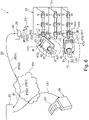
- the figure 1 shows a system 1 installed in the premises of a supermarket for radio communication with electronic price display signs that implement display devices, hereinafter referred to as ESL 2-10 and ELS 11-19 for short, with the aid of which a self-checkout system is implemented.
- Each ESL 2-19 has a display 40 and is mounted on shelves 20-22 of a shelf 23 corresponding to products (not shown) positioned on the shelf for which price and product information is displayed.
- the system also has two base stations 25 and 26, the first base station 25 with the ELS 2 - 10, symbolized by first radio signals FS1, and the second base station 26 with the ELS 11 - 19, symbolized by second radio signals FS2, using a proprietary first communication protocol is in radio contact.
- the logical Allocation (eg through different radio channels) of the groups of ESL 1-10 and 11-19 to the respective base station 25, 26 is visualized with the aid of line 30.
- the radio areas do not have to be spatially separated, as is the case in the figure 1 shown for the sake of clarity.
- the radio areas can also overlap (eg in areas).
- the system 1 also has a WLAN access point, called access point 27 for short below, which, shown centrally, covers the two areas to the left and right of line 30 in terms of radio technology. However, there can also be several access points 27 in order to supply the entire sales room with radio technology. With the help of the WLAN access point 27, merchandise management-related communications can be processed with portable merchandise management devices (not shown).
- the access point 27 and the two base stations 25, 26 are connected via a wired network 28 to an inventory management system server 29 of the supermarket.
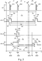
- the state diagram has the time t on the abscissa axis and the communication states of the ESLs 7 - 9 cited by way of example and of the first base station 25 on the ordinate axis.
- T indicates a transmission state and R a reception state of the base station 25 and E an active state ready to receive and S an energy-saving sleep state of the ESL 7 - 9 in which there is no readiness to receive.
- N time slots Z1 . . . ZN (eg 256) with an identical time slot duration DS (eg approx. 58 milliseconds) are available during a time slot cycle duration DC (eg 15 seconds).
- the base station 25 (identified with the symbol "ST") changes between the transmission state T and the idle state R.
- the transmission state T is always assumed at the beginning of a time slot Z1...ZN and is used for a synchronization data signal Duration DSD (or transmission duration DSD of the synchronization data signal SD) maintained in order to send the respective applicable time slot symbol ZS1, ZS2, ... ZSN with the respective synchronization data signal SD.
- Duration DSD or transmission duration DSD of the synchronization data signal SD
- ZSN comes the serial number of the respective time slot Z1 ... ZN in the Order of occurrence of the time slots Z1 ... ZN used. Consequently, the first time slot Z1 in hexadecimal notation (identified by "Hex") with the time slot symbol Hex 00, the second time slot Z2 with the time slot symbol Hex 01 etc. and the last time slot ZN (in the present example the two hundred and fifty-sixth time slot Z256 with the time slot symbol Hex FF marked.
- the first ESL 7 is in the synchronous state. It wakes up from its sleep state S at a first wake-up time TA1 and changes to its ready-to-receive active state E with a relatively short lead time DV before an expected occurrence of a synchronization data signal SD, receives the synchronization data signal SD during a reception period DE with the first timeslot symbol ZS1 (Hex 00), determines by comparing the least significant byte B0 of its hardware address (Hex 00) with the received timeslot symbol ZS1 that the first timeslot Z1 intended for the first ESL 7 is indicated (correspondence of the bytes to be compared: B0 of the hardware address and first time slot symbol ZS1), retains the parameters of its time control stage used to control the wake-up for waking up in the subsequent time slot cycle in order to define the new wake-up time and changes back to the sleep state S with a relatively short follow-up time DN after expiry of the intended sleep state ver wake up time DR according to plan at the new (second) wake
- the third ESL 9 is in the asynchronous state before a synchronization point in time TSY, which is indicated by the broken line of the arrow P1 running parallel to the time axis. It wakes up at a randomly selected first wake-up time TA1 and changes from its sleep state S to the active state E ready to receive and waits in this state until the next occurrence of the synchronization data signal SD is received, with the second time slot symbol ZS2 ( Hex 01) is received.
- the third ESL 9 recognizes from the least significant byte B0 (Hex 00) of its hardware address that the specific time slot in the present time slot cycle already belongs to the past and consequently the next time slot with the time slot symbol Hex 00 is only to be expected in the next time slot cycle, and calculates that the currently recognized time slot Z2 is one time slot next to its original time slot Z1, which is referred to below as the time slot difference.
- its time control stage is now programmed so that the new wake-up time TA2 lies before the occurrence of the first time slot Z1 of the subsequent time slot cycle, as in the case of an ESL in the synchronous state with said lead time DV.
- the waiting time DSA in the sleep state S is calculated automatically.
- the third ESL 9 is thus again in the synchronous state, which is indicated by the second arrow P2 with a solid line, and changes from the active state E to the sleep state S, after the dwell time DSA has elapsed at the new wake-up time TA2 to change its active state E.
- the ESL 8 has a processing stage 31 for providing operating states such as the active state and the sleep state.
- the processing stage 31 is by means of a microcontroller, an internal memory 32 and a co-processor 33, which is coupled to transmit / receive means 34 for communication with the base station 25, 26 on.
- the processing stage 31 is coupled to an external memory 36 and to a display device 38 via a first bus system 35 .
- the display device 38 has its own microcontroller 39 for display-related data processing and an electronic ink-based display 40 for visualizing information 41 .
- a voltage supply stage 42 which is implemented using a battery 42, provides a first supply voltage VCC1 with respect to a reference potential GND for the electronic components described.
- the electronic components described are in the figure 3 identified as display module 43.
- the co-processor 33 and the transmitting/receiving means 34 form a first radio interface 44 for communication according to the time slot communication protocol described above. With the help of the first radio interface 44 can be a product data set PD and a Availability data record VD from the base station 25, 26 to the relevant ESL 2 - 19 transmit.
- the ESL 8 also has a second radio interface implemented with the aid of an NFC module 45 .
- the NFC module 45 has analog components 46, which include the inductive coupling components 47, visualized as a coil, for contactless communication with another NFC-enabled device, and the power supply components 48. If there is an inductive coupling, the voltage supply components 48 generate a second supply voltage VCC2 compared to the reference potential GND for supplying the NFC module 45, which enables its digital components to be operated.
- the digital components are implemented using a second microcontroller 49, which also has an internal memory 50 and is connected to the analog components 46 for communication in accordance with an NFC communication protocol.
- the NFC module 45 is connected to the display module 43 , in particular to the first microcontroller 31 , by a second bus 51 .
- the operating system of the NFC module 49 can be stored in the internal memory 50 or in one of the memories 36, 32 of the display module, which the second microcontroller 49 can access. As soon as it is processed, it makes the NFC communication protocol available.
- the system components described so far essentially form stationary, i.e. permanently installed components of a self-checkout system. It stores ESL 13 a first product and availability data set PD1 and VD1, ESL 2 a second product and availability data set PD2 and VD2 and ESL8 the third product and availability data set PD3 and VD3.
- ESL 13 a first product and availability data set PD1 and VD1
- ESL 2 a second product and availability data set PD2 and VD2 and ESL8 the third product and availability data set PD3 and VD3.
- the three availability data sets VD1-VD3 indicate unrestricted availability of the associated product data sets PD1-PD3.
- Each of the product data sets PD1-PD3 can be queried using a self-check request.
- An Indian figure 1 Smartphone 57 shown at three different points in time at three positions I, II, III immediately adjacent to ESLs 2, 8, 13 and within their NFC communication range implements a mobile self-checkout device.
- the smartphone 57 has, as in the figure 4 illustrated, a mobile radio interface 54 for communication in a mobile radio network of a mobile radio operator, an NFC-enabled device radio interface 59 for communication with the NFC module 45, a control stage 51 for controlling a self-check request, a detection stage 53 for detecting a confirmation from a user with the help of one in the figure 1 visible fingerprint sensor 61, and a product list storage stage 52 for storing one or more product data records PD received from an ESL 2-19 as a result of the self-check request.
- a data bus 56 connects the components 51, 52, 53, 54, and 59.
- the control stage 51 also has an in the figure 1 visualized touchscreen display 60, with the help of which plain text information KT1 - KT3 (see figure 1 ) for the product data records PD1 - PD3 received from the ESL 13, 2, 8 can be visualized.
- the smartphone 57 also stores device identification data ID, which are sent along with the communication via the respective interface.
- an NFC communication with the NFC module 45 of the ESL 13 is, for example, to any and in the figure 1 illustrated communication time TK set up, a self-check query is sent from the smartphone 57 specifying the device identification data ID to the ESL 13, the NFC module 45 reads the first product data record PD1, which is identified as unrestrictedly available by the first availability data record VD1, and sends it to the smartphone 57 by means of NFC communication, where its plain text information KT1 (product and price) is visualized as a new entry between angle brackets on the display 60, and with the help of the detection stage 53 the fingerprint of a finger 62 of the user is checked as approval for self-checking and If the test result is positive, the first product data record PD1 is stored using the product list storage stage 52. The product is taken by the user before or after from the shelf space where the ESL 13 is mounted and placed in
- the smartphone 57 is then transferred to the ESL 2, where the previously described process of self-checking is carried out again for the second product data record PD2. Subsequently, the smartphone 57 is tolerated for the ESL 8 and the self-checking process is carried out a final time, so that the three product data records PD1-PD3 are now in the smartphone 57.
- a payment transaction is carried out for each of the product data sets PD1-PD3 immediately when it is stored, or a joint payment transaction is carried out for all three together, finally.
- FIG 5 is a self-checking system with search engine feedback function visualized, based on the in the 1 shown left half of the self-service shop was omitted for reasons of clarity.
- the smartphone 57 is first used, for example, at a position I outside the premises of the supermarket to search for product information, an Internet-based search engine 63 being contacted via the Internet 64 with the search query and the device identification data ID.
- the search query concerns details of the product identified by the ESL 2 in the supermarket.
- This search request is stored in the search engine 63 together with the device identification data ID and the search result.
- the user of the smartphone 57 carries out a self-checkout request from the ESL 2 on the premises of the supermarket and confirms the self-checkout (eg payment for the relevant product).
- the ESL 2 then transfers the device identification data ID to the base station 25 and from there to the merchandise management system server 29 of the supermarket, where the connection between the product that is assigned to the ESL 2 and the ESL 2 is known.
- the server 29 then forwards a product identification, e.g. the first product data record PD1 together with the device identification data ID to the search engine 63, where the information gap between the search query for a product or search result and the actual product purchase can be closed by the feedback from the ESL 2.
- the original search query may be accompanied by advertisements related to the product being searched or to the general User behavior of the user have been transmitted to the smartphone 57.
- this advertising led to another purchase or not can now also be determined using the measures described. For example, if the advertisement relates to the product marked with the help of the ESL 8 and the user carries out the self-checkout process for this product as well, the question posed can be answered positively with the help of the feedback from the ESL 8 on the search engine side.
- a cloud or Internet-based merchandise management system can also be implemented in which the functionality of the figure 1 Server 29 shown is relocated to a data processing system 65 of a provider for outsourced merchandise management services.
- the device identification data ID are delivered directly from the base station to the remote data processing system 65 .
- a connection is known there between the respective ESL 2 - 19 supplying the device identification data ID and the products assigned to them, consequently the product data records PD1 - PD19 are also available there. If the product data records are not known there, they can be used as in the 6 for the product data records PD1 and PD2 are supplied to the data processing system 65, indicated in brackets.
- a receipt printer 66 installed locally in the supermarket can be controlled via the Internet 64 with print data DD and a receipt 67 can be printed out, which has all those products for which a payment transaction was carried out.
- the invention also allows self-checkout of weight products, the price of which is only determined by weighing the product.
- a network-enabled scale with an ESL according to the invention (see figure 3 ) be equipped.
- a product is placed on the scale by the customer, the customer selects the product or product class on the scale screen, the scale determines the weight and creates and transmits the product data record to the ESL using the base station with which the scale is equipped.
- the user now uses his smartphone 57 to make a self-check request to this ESL, as a result of which the product data record of the weight product is transmitted to the smartphone 57 .
- the availability record can be used to make the product record in question retrievable only once and it in any case after a preset period of time in the absence of the self-check request (e.g. 30 seconds) in order to be able to use the scale as quickly as possible for the next weighing process.
- the identification data ID when entering a self-service shop, can be queried by the self-check device 57 using a suitable terminal and transferred to the merchandise management system.
- Individual product data sets PD are transmitted to all or selected ESLs for the user in question or his device in order to make individualized offers available for this user (e.g. according to his past shopping behavior).
- the availability of the individual product data records for the relevant device 57 is controlled with the aid of the availability data record VD.
- the individual product data records PD are therefore only transmitted to this relevant device 57 in the event of a self-checkout request.
- other product records are stored in the ESLs and sent to the requesting device in the event of a self-check request.
- each self-checkout of a product can involve a payment transaction for that product.
Description
- Die Erfindung betrifft eine Anzeigevorrichtung zum Anzeigen einer Preis- und / oder Produktinformation, ein Selbstverbuchungsgerät zum Durchführen einer Selbstverbuchung, sowie ein Selbstverbuchungssystem.
- Eine bekannte Anzeigevorrichtung, auch elektronisches Preisanzeigeschild, im Fachjargon auch "Electronic Shelf Label", kurz ESL genannt, steht im Betrieb mit einer Basisstation in Funkkontakt. Über diesen Funkkontakt wird die Anzeigevorrichtung mit einer Preis- und / oder Produktinformation versorgt und visualisiert diese mit ihrer Anzeigeeinrichtung. Das ESL ist üblicherweise an einer Regalschiene eines Regals befestigt, auf dem das betreffende Produkt gelagert bzw. angeboten wird, zu dem die Preis- und / oder Produktinformation korrespondiert. Produkte können mit "Radio-Frequency-Identification-Device" (abgekürzt RFID) Etikett und / oder Strichcode zu ihrer Identifikation ausgestattet sein. Ein solches Etikett, seine Verwendung wie auch ein System mit solchen Etiketten ist beispielsweise in der
US 2015/0035674 A1 offenbart. Ein Kunde wählt Produkte zum Kauf aus, legt sie in seinen Einkaufswagen, fährt mit dem Einkaufswagen bis zum Kassenschalter und legt die Produkte zur Erfassung zwecks Verrechnung auf ein Förderband. Dort werden die Produkte, wenn ausgestattet mit RFID-Etiketten, entweder mit Hilfe einer RFID-Leseeinrichtung (RFID-Reader) oder, wenn ausgestattet mit einem Strichcode, mit Hilfe einer Strichcode-Leseeinrichtung erfasst und ein Kassenbon, der Produkte und zugehörige Preise auflistet, erstellt. Die Bezahlung des Gesamtpreises erfolgt durch den Kunden per Barzahlung, per Kreditkarte oder per "Near-Field-Communication" (abgekürzt NFC) fähigem Mobiltelefon mit entsprechender Bezahlapplikation (Bezahlsoftware) auf dem Mobiltelefon. - Produkte mit RFID-Etiketten auszustatten und RFID-Reader bei jedem Kassenschalter zur Erfassung der Produkte zu installieren ist relativ teuer. Zudem hat sich die RFID-mäßige Erfassung der Produkte beim Kassenterminal zwecks Verrechnung als unzuverlässig und langsam erwiesen. Nicht erfasst Produkte müssen neuerlich an dem RFID-Reader vorbeibewegt werden oder manuell mit Hilfe ihres Strichcodes erfasst werden. Produkte, für die eine Ausstattung mit RFID-Etikett nicht in Frage kommt, müssen jedenfalls manuell erfasst werden, was entweder mit Hilfe des Strichcodes des Produkts oder durch manuelle Eingabe einer Produktnummer des Produkts in das Kassensystem oder Auswahl des Produkts am Kassensystem geschieht. Dies führt zu unbefriedigenden Arbeitsabläufen (langsame Erfassung, Fehleranfälligkeit, usw.).
- Die Erfindung hat sich daher die Aufgabe gestellt, die eingangs erwähnten Probleme zu beseitigen und eine effizientere Erfassung der Produkte zu ermöglichen.
- Diese Aufgabe wird durch eine Anzeigevorrichtung gemäß Anspruch 1 gelöst. Der Gegenstand der Erfindung ist daher eine Anzeigevorrichtung ausgebildet als elektronisches Preisanzeigeschild, aufweisend eine Speicherstufe zur Speicherung eines Produktdatensatzes, der bei einer Kommunikation mit einer Basisstation über eine erste Funkschnittstelle der Anzeigevorrichtung empfangen wurde, wobei die Speicherstufe einen mit dem Produktdatensatz verknüpften Verfügbarkeitsdatensatz aufweist, mit dessen Hilfe die Verfügbarkeit des Produktdatensatzes steuerbar ist, und eine zweite Funkschnittstelle zur RFID- oder NFC-Kommunikation mit einem Selbstverbuchungsgerät, wobei die Anzeigevorrichtung zum Bearbeiten einer Selbstverbuchungs-Anfrage empfangen von einem Selbstverbuchungsgeräts zwecks Übertragung des Produktdatensatzes über die zweite Funkschnittstelle ausgebildet ist, wobei die Verfügbarkeit des Produktdatensatzes eine zeitliche Verfügbarkeit betrifft, in der besagter Produktdatensatz verfügbar ist, und die Anzeigevorrichtung dazu ausgebildet ist, den Verfügbarkeitsdatensatz zu prüfen, ob der Produktdatensatz zeitlich beschränkt verfügbar ist, und die Anfrage innerhalb der zeitlichen Verfügbarkeit mit besagtem Produktdatensatz oder außerhalb der zeitlichen Verfügbarkeit mit einem anderen Produktdatensatz oder gar nicht oder auf andere Weise zu bearbeiten.
- Auch ist ein Selbstverbuchungsgerät offenbart, das aufweist eine zur zweiten Funkschnittstelle der erfindungsgemäßen Anzeigevorrichtung kompatible Geräte-Funkschnittstelle zur Kommunikation, insbesondere zur RFID- oder NFC-Kommunikation, mit besagter Anzeigevorrichtung, und eine Steuerstufe zum Steuern einer Selbstverbuchungs-Anfrage über die Geräte-Funkschnittstelle an die Anzeigevorrichtung zwecks Übertragung eines Produktdatensatzes von der Anzeigevorrichtung über die Geräte-Funkschnittstelle an das Selbstverbuchungsgerät.
- Die Aufgabe wird zudem durch ein Selbstverbuchungssystem gemäß Anspruch 10 gelöst. Der Gegenstand der Erfindung ist somit ein Selbstverbuchungssystem aufweisend eine Basisstation zur Kommunikation mit einer Anzahl von erfindungsgemäßen Anzeigevorrichtungen und zumindest eine erfindungsgemäße Anzeigevorrichtung und zumindest ein erfindungsgemäßes Selbstverbuchungsgerät aufweisend eine zur zweiten Funkschnittstelle der Anzeigevorrichtung kompatible Geräte-Funkschnittstelle zur RFID- oder NFC-Kommunikation mit besagter Anzeigevorrichtung, und eine Steuerstufe zum Steuern einer Selbstverbuchungs-Anfrage über die Geräte-Funkschnittstelle an die Anzeigevorrichtung zwecks Übertragung eines Produktdatensatzes von der Anzeigevorrichtung über die Geräte-Funkschnittstelle an das Selbstverbuchungsgerät.
- Die Aufgabe wird zudem durch eine Verwendung gemäß Anspruch 11. Der Gegenstand der Erfindung ist daher eine Verwendung einer erfindungsgemäßen Anzeigevorrichtung zur räumlich lokalisierten Bereitstellung eines individuellen Produktdatensatzes in einem Selbstverbuchungssystem zwecks lokaler Übertragung des Produktdatensatzes mit Hilfe einer RFID- oder NFC-Kommunikation von der Anzeigevorrichtung an ein bei der Anzeigevorrichtung mit Hilfe einer Selbstverbuchungs-Anfrage anfragendes Selbstverbuchungsgerät.
- Mit den erfindungsgemäßen Maßnahmen geht der Vorteil einher, dass eine bestehende Infrastruktur eines Systems von elektronischen Anzeigevorrichtungen, insbesondere elektronische Preisanzeigeschilder, im Fachjargon auch "Electronic Shelf Labels", nachfolgend kurz ESLs genannt, als Systemkomponente zur Selbstverbuchung bzw. Selbstbezahlung (im Fachjargon "Self-Checkout-System" bezeichnet) nutzbar ist.
- Ein Produktdatensatz kann aus einer Anzahl von Bits, Bytes oder größeren Datenmengen bzw. Struktur bestehen. Der Produktdatensatz kann einen Verweis aufweisen, der es dem Selbstverbuchungsgerät, das den Produktdatensatz empfängt, ermöglicht, über eine andere Kommunikationsverbindung (z.B. eine Internetverbindung mit einem Produktbeschreibungs- und / oder Produktpreis-Datenserver über WLAN oder UMTS) eine Information zum Produkt und / oder dessen Prei abzufragen, um diese Information dann weiterzuverarbeiten. Bevorzugt weist jedoch der Produktdatensatz selbst die Information zum Produkt und / oder dessen Preis auf, um direkt weiterverarbeitet zu werden.
- Besagte ESL sind in den Verkaufsräumlichkeiten eines Selbstbedienungs-Einzelhändlers an den Regalen befestigt, auf denen die ihnen zugeordneten Produkte stehen. Will nun eine Kunde ein Produkt kaufen, entnimmt er es aus dem Regal und hält sein Selbstverbuchungsgerät (z.B. sein entsprechend ausgerüstetes Smartphone) in die Nähe des ESL oder berührt damit das ESL. Das Selbstverbuchungsgerät, auf dem eine Selbstverbuchungs-Applikation abgearbeitet wird, nimmt mit Hilfe seiner Geräte-Funkschnittstelle Kontakt zu der zweiten Funkschnittstelle des ESL auf und übermittelt eine Selbstverbuchungs-Anfrage an das ESL, z.B. mit Hilfe eines Selbstverbuchungs-Befehls, der dort erkannt und verarbeitet wird. Darauf reagiert das ESL mit einer Übertragung des Produktdatensatzes über die zweite Funkschnittstelle an das Selbstverbuchungsgerät, das die weitere Verarbeitung des Produktdatensatzes übernimmt.
- In Abkehr von bekannten Self-Check-Out-Systemen, bei denen die Buchungsvorgänge für alle zu erfassenden Waren üblicherweise bei einem zentralen Kassentisch erfolgen, erfolgt der individuelle Buchungsvorgang für das betreffende Produkt im Wesentlichen am Platz des ESL (also am Regalplatz, wo das Produkt gelagert ist), zu dem das Produkt zugeordnet ist.
- Die ESL sowie ihre Kommunikationsinfrastruktur (Basisstation und damit gekoppeltes Warenwirtschaftssystem) bilden somit einen Teil eines Selbstverbuchungssystems, wobei mehrere ESL zur räumlich verteilten Bereitstellung der individuellen Produktdatensätze an jenen Orten verwendet werden, an denen sich auch die betreffenden Produkte befinden. Die Verteilung der Produktdatensätze auf die individuellen ESL erfolgt automatisch und kann jederzeit unproblematisch und dynamisch an die sich im Selbstbedienungsladen ergebende Situation angepasst werden. Geht z.B. in einem Regal ein Produkt aus und wird dort ein anderes Produkt nachgeschlichen, kann dem dort befindliche ESL durch Kommunikation über die Basisstation der neue Produktdatensatz sofort mitgeteilt werden.
- Vorteilhaft hervorzuheben ist hierbei, dass elektronische Produktetiketten befestigt an oder integriert in den jeweiligen Produkten überflüssig sind, die einzelnen Produkte also nicht mehr mit individuellen RFID-Etiketten ausgestattet sein müssen. Dies bringt ein erhebliches Einsparungspotential mit sich und löst auch das ökologische und logistische Problem des Recyclings solcher elektronsicher Produktetiketten. Auch wird der Erfassungsvorgang der Produkte wesentlich beschleunigt, weil die Produkte direkt bei ihrem Regal vom Kunden selbst erfass, also verbucht werden.
- Wird in den ESL mit Hilfe des Produktdatensatzes die individuelle Produkt - und Preisinformation als solche bereitgestellt, so können die Selbstverbuchungen offline, also ohne zusätzliche Internetverbindung auf der Seite des Selbstverbuchungsgeräts erfolgen. Dies sorgt für störungsfreie und rasche Buchungsvorgänge und schützt vor kriminell motivierter Einflussnahme.
- Der Gesamtvorgang des Einkaufens wird für den Kunden zudem wesentlich transparenter, weil er selbst die Verbuchung durchführt und somit immer vollen Überblick und Kontrolle über die gebuchten Waren hat. Die vom Kunden oft als störend empfundene Problematik einer möglicherweise fehlerhaften Buchung am Kassentisch (z.B. durch automatische RFID-basierte oder personalunterstütze manuelle Buchung) wird somit vollständig vermieden.
- Es kann die zweite Funkschnittstelle auf kapazitive und/oder induktive Weise zum Kommunizieren ausgebildet sein. Sie kann zur Kommunikation gemäß einer Bluetooth-Spezifikation (z.B. definiert von SIG) oder auch gemäß einer ZigBee-Spezifikation ausgebildet sein. Für beide Kommunikationsarten ist jedoch die relativ weite Funk-Reichweite eher problematisch, da sie eine Benutzerinteraktion zur Auswahl von verschiedenen verfügbaren Kommunikationspartner (ESLs) erfordert, wenn sich ihre Kommunikationsbereiche überlagern.
- Gemäß einer bevorzugten Ausbildung ist die zweite Funkschnittstelle zur Kommunikation gemäß einer RFID-Spezifikation (bzw. eines RFID-Standards) ausgebildet, wie beispielsweise ISO/IEC 10536, 14443, 15693, 10373 oder VDI 4470, 4472 oder ISO/IEC 18000 oder EPCglobal oder ISO/IEC 15961, 15962 oder zukünftig Spezifikationen. Als besonders vorteilhaft hat es sich erwiesen, wenn die zweite Schnittstelle zur Kommunikation gemäß einer NFC- Spezifikation ausgebildet ist, wie beispielsweise ISO/IEC 13157, -16353, -22536, -28361 oder zukünftiger Spezifikationen. In diesen Ausbildungsformen hat sich insbesondere die relativ kurze Funkreichweite (max. ca. 10, insbesondere 5 Zentimeter) als sehr vorteilhaft erwiesen, weil sie eine durch den Kunden selbst herbeigeführte räumlich eindeutige Zuordnung zwischen dem betreffenden ESL und dem Selbstverbuchungsgerät verlangt, um eine Selbstverbuchung durchzuführen.
- Ein Selbstverbuchungsgerät kann z.B. ein portables Medienwiedergabegerät ohne Telefonfunktionalität, ein Smartphone, eine Smartwatch oder auch ein handlicher Tablet-Computer mit entsprechender Geräte-Funkschnittstelle sein. Seine Steuerstufe ist mit Hilfe eines Prozessors realisiert, auf der eine entsprechende Software oder Applikation abläuft, welche die Selbstverbuchungs-Anfrage steuert, konkret mit Hilfe des entsprechenden Kommunikationsprotokolls eine Verbindung mit der Anzeigevorrichtung aufbaut, einen Selbstverbuchungs-Anfragebefehl an diese sendet, Antwortdaten von ihr empfängt und im Sinne der Selbstverbuchung weiterverarbeitet.
- Weitere, besonders vorteilhafte Ausgestaltungen und Weiterbildungen der Erfindung ergeben sich aus den abhängigen Ansprüchen sowie der nachfolgenden Beschreibung. Merkmale und entsprechende Vorteile, die im Zusammenhang mit einer Kategorie der Ansprüche erwähnt wurden, können auch bei einer anderen Kategorie der Ansprüche vorgesehen sein bzw. dort zum Tragen kommen.
- Das ESL weist ein Anzeigemodul zur Anzeige von Preis und / oder Produktinformationen auf. Das Anzeigemodul kann einen ersten Mikrokontroller, der im Wesentlichen die Verarbeitungsstufe realisiert, eine Batterie, die eine Versorgungsspannung von z.B. drei Volt bereitstellt und das Anzeigemodul speist, aufweisen. Der Mikrokontroller kann einen internen Speicher aufweisen oder auch mit einem externen Speicher verbunden sein. Der Mikrokontroller kann als einen Bestandteil der ersten Funkschnittstelle einen integrierten Co-Prozessor sowie weitere elektronische Komponenten zur Realisierung der ersten Funkschnittstelle aufweisen bzw. mit Ihnen gekoppelt sein, sodass die Kommunikation gemäß einem ersten Funk-Kommunikationsprotokoll mit Hilfe des Co-Prozessors durchgeführt wird. Damit verbunden ist eine erste Antenne der ersten Funk-Schnittstelle. Zudem weist die Hardware des Anzeigemoduls eine Anzeigeeinrichtung auf, die über einen mit dem ersten Mikrokontroller gekoppelten zweiten Mikrokontroller verfügen kann, um von dem ersten Mikrokontroller an sie delegierte anzeigespezifische Aufgaben autonom zu erledigen. Die Anzeigeeinrichtung kann mit Hilfe von LCD-Technologie, bevorzugt jedoch auch mit extrem energiesparender Electronic-Ink-Technologie (auch E-Ink als Synonym für elektronisches Papier genannt) realisiert sein.
- Das bei der ersten Funkschnittstelle zur Anwendung kommende erste Kommunikationsprotokolls kann beispielsweise gemäß dem "ZigBee" Standard, dem "BlueTooth" Standard oder auch gemäß einem proprietären Protokoll realisiert sein. Die erste Funkschnittstelle und gegebenenfalls auch die Verarbeitungsstufe weisen eine entsprechenden Ausbildung der Hardware sowie eine geeignete Software auf, die auf dieser Hardware ausgeführt wird, um die Kommunikation gemäß dem jeweiligen Kommunikationsprotokoll zu erlauben.
- Gemäß einem bevorzugten Ausführungsbeispiel kommt bei der ersten Funkschnittstelle ein proprietäres Funk-Kommunikationsprotokoll, das ein Zeitschlitzkommunikationsverfahren implementiert, zur Anwendung, mit dessen Hilfe mehrere ESL mit einer Basisstation kommunizieren können. Eine Basisstation dient als Schnittstelle zwischen einer kabelgebundenen Kommunikation mit z.B. einer Datenverarbeitungseinrichtung (z.B. einem Server) und einer kabellosen Kommunikation mit anderen Geräten, im vorliegenden Fall den ESL. Gemäß diesem Protokoll können die ESL zunächst bei einer Basisstation registriert bzw. ihr zugeordnet werden, um für eine FuncKommunikation mit dieser Basisstation benutzbar zu sein. Bei der Registrierung wird jedem ESL ein vordefinierter, individueller Zeitschlitz für die Kommunikation mit der Basisstation zugewiesen. Dabei kommen z.B. innerhalb von n Sekunden, z.B. 15 Sekunden, m Zeitschlitze, z.B. 255 Zeitschlitze, zum Einsatz. Die n Sekunden bilden einen Zeitschlitzzyklus, der sich fortwährend wiederholt und auch Synchronisationszyklus genannt wird. In diesem Zeitschlitzkommunikationsverfahren stehen also m Zeitschlitze innerhalb eines Synchronisationszyklus für eine Kommunikation mit ESLs zur Verfügung. Jedes der ESL ist einem der Zeitschlitze zugeordnet, wobei einem bestimmten Zeitschlitz auch mehrere ESLs zugeordnet sein können, z.B. 2, 3 oder 4 ESLs. Innerhalb von einer Minute existieren 4 Synchronisationszyklen mit je 255 Zeitschlitzen, sodass sich mit z.B. 2 ESLs pro Zeitschlitz eine Gesamtanzahl von 2040 ESLs adressieren lässt. Wenn in den Verkaufsräumlichkeiten eines Einzelhandelsunternehmens mehrere Basisstationen installiert sind, lassen sich Gruppen von ESLs, die der jeweiligen Basisstation zugeordnet sind, steuern.
- Die ESLs können sich mit Hilfe einer Synchronisations-Signalstruktur (z.B. ein relativ kurzes Signal am Anfang des jeweiligen Zeitschlitzes) ausgesandt durch die Basisstation in jedem der Zeitschlitze mit dem Zeitraster des Zeitschlitzkommunikationsverfahrens erstmalig synchronisieren, um den Kommunikationsbetrieb mit der Basisstation zu starten, im Verlauf des Betriebs re-synchronisieren, wenn sie den synchronen Zustand durch irgendwelche Umstände verloren haben, und synchron halten, wenn kleinere Abweichungen vom synchronen Zustand vorliegen, die durch Ungenauigkeiten wie z.B. eine Drift ihrer inneren Uhr bedingt sind. Gemäß dem ersten Kommunikationsprotokoll ist jeder Zeitschlitz durch ein eindeutiges Zeitschlitzsymbol gekennzeichnet, wobei die Basisstation dazu ausgebildet ist, für den momentan vorliegenden Zeitschlitz ein Synchronisations-Datensignal aufweisend das Zeitschlitzsymbol auszusenden. Das ESL ist zum Wechseln von einem Schlaf- bzw. Ruhe-Zustand, nachfolgend kurz Schlaf-Zustand genannt, in einen Aktiv-Zustand zu einem Aufwachzeitpunkt ausgebildet und empfängt das Synchronisations-Datensignals im Aktiv-Zustand. Wenn das empfangene Zeitschlitzsymbol einen für das ESL bestimmten Zeitschlitz anzeigt definiert das ESL einen zu dem nächsten Auftreten des für sich bestimmten Zeitschlitzes korrespondierenden neuen Aufwachzeitpunkt in einem auf den momentan vorliegenden Zeitschlitzzyklus folgenden Zeitschlitzzyklus.
- Jedes ESL stellt seinen Synchronismus mit der Basisstation alleine durch den Umstand des Erkennens des Zeitschlitzsymbols fest, das zu dem von ihr erwarteten Zeitpunkt bzw. in einem Erwartungszeitfenster auftritt und den für das ESL bestimmten Zeitschlitz anzeigt. Nachdem das ESL seinen Synchronismus wie zuvor erörtert festgestellt hat, reicht es grundsätzlich aus, wenn es wieder in den Schlaf- Zustand wechselt, weil der nächste Aufwachzeitpunkt automatisch durch den ihm bekannten Zeitraster des Zeitschlitzkommunikationsverfahrens bekannt ist. Das Definieren des neuen Aufwachzeitpunktes kann sich somit darauf beschränken, dass eine z.B. Zeitsteuerstufe (z.B. ein Timer) des ESL mit den bereits zuvor zum Wechseln vom Schlaf-Zustand in den Aktiv-Zustand benutzen Timing-Parameter neu gestartet wird. Danach kann das ESL wieder in den Schlaf-Zustand wechseln und dort verharren, bis dass ausgelöst durch die Zeitsteuerung wieder ein Aufwachen und Wechseln von dem Schlaf- Zustand in den Aktiv-Zustand zu dem neuen Aufwachzeitpunkt in dem nächsten Zeitschlitzzyklus durchgeführt wird. Das ESL muss jedoch nicht zwingend für den Rest des für sich bestimmten Zeitschlitzes im Schlaf-Zustand verharren, sondern kann auch während des Zeitschlitzes oder auch des Zeitschlitzzyklus weitere Aufgaben in einem Aktiv-Zustand bearbeiten. Die zuvor erörterte Zeitsteuerung arbeitet dann im Hintergrund unabhängig von seinen weiteren Aktivitäten. Das Zeitschlitzsymbol kann grundsätzlich beliebig gewählt werden. Als besonders vorteilhaft hat es sich erwiesen, wenn das Zeitschlitzsymbol mit Hilfe einer das ESL eindeutig identifizierenden Hardware-Adresse des ESL gebildet ist, bevorzugt durch die niederwertigsten Bits oder das niederwertigste Byte der Hardware-Adresse.
- Das ESL weist zudem ein weiteres damit elektronisch verbundenes Funk-Modul mit besagter zweiten Funkschnittstelle auf.
- Das Anzeigemodul, insbesondere der erste Mikrokontroller ist mit dem weiteren Funk-Modul gekoppelt. Auch das zweite Funk-Modul kann neben den für die physikalische Übermittlung von Signalen zur Funkkommunikation nötige Hardware einen eigenen, dritten Mikrokontroller sowie einen eigenen Speicher aufweisen. Wird die zweite Funkschnittstelle gemäß einer RFID oder NFC-Spezifikation ausgebildet, kann sie die für Ihren Betrieb nötige Versorgungsspannung aus den empfangenen Signalen generieren und unabhängig von besagter Batterie betrieben werden.
- Soweit ein Produktdatensatz in dem ESL existiert und hinsichtlich seiner Verfügbarkeit keine Beschränkung besteht, wird der Produktdatensatz als Folge der empfangenen Selbstverbuchungs-Anfrage von dem ESL an das Selbstverbuchungsgerät übermittelt.
- Der Produktdatensatz kann in dem Anzeigemodul in einem für den Mikrocontroller des Anzeigemoduls bestimmten Speicher gespeichert sein. Der Zugriff auf diesen Speicher kann von dem ersten Mikrocontroller aus erfolgen, was jedoch seinen aktiven Betriebszustand voraussetzt. Kommt jedoch ein Kommunikationsprotokoll zur Anwendung, welches einen möglichst energiesparenden Betrieb eines ESL erlaubt, sowie vorangehend erörtert, ist es von Vorteil, wenn der Zugriff auf besagten Speicher von dem dritten Mikrocontroller aus, welcher einen Bestandteil des weiteren Funkmoduls bildet, erfolgt. Wird beispielsweise der dritte Mikrocontroller als Folge einer RFID- oder NFC-Kommunikation mit Hilfe der zur Kommunikation nötigen Funksignale mit Energie versorgt, kann der zweite Mikrocontroller ohne Belastung der internen Batterie des ESL den Produktdatensatz auslesen und übergeben. Besonders vorteilhaft ist es, wenn die mit Hilfe der Funksignale realisierte Energieversorgung auch besagten Speicher versorgt, in dem der Produktdatensatz gespeichert ist. Dies kann so realisiert sein, dass bei vorliegen einer solchen (extern) funksignalbasierten Energieversorgung mit Hilfe geeigneter Schaltmittel auch besagter Speicher im Anzeigemodul an diese Energieversorgung angekoppelt wird. Besonders bevorzugt handelt es sich bei dem Speicher, der den Produktdatensatz speichert, um einen Speicher der weiteren Funkschnittstelle und der erste Mikrocontroller hat für die Zwecke des Anlegens bzw. Veränderns des Produktdatensatzes vom Anzeigemodul aus Zugriff auf diesen Speicher.
- Das erfindungsgemäße ESL kann im Rahmen der Selbstverbuchungsanfrage auch den Lagerstand zu dem durch die Selbstverbuchungsanfragen betroffenen Produkt mit Hilfe der ersten Funkschnittstelle abfragen. Dies kann von Vorteil sein, um im zentralen Warenwirtschaftssystem des Einzelhändlers den korrekten Lagerstand abzubilden. Auch kann dies das Problem eines augenscheinlich im Regal vergriffenen Produkts lösen. Ergibt nämlich, dass die Bearbeitung dieser Abfrage z.B. durch das Warenwirtschaftssystem, dass das betroffene Produkt noch im Lager verfügbar ist, kann dies in Folge über die zweite Funkschnittstelle an das Selbstverbuchungsgerät kommuniziert werden oder auch gleich ein Mitarbeiter des Kaufhauses mit dem Nachschlichten des betroffenen Produkts beauftragt werden. Der Kaufwunsch eines Kunden kann somit just-in-time befriedigt werden.
- Gemäß einem weiteren Aspekt der Erfindung weist die Speicherstufe einen mit dem Produktdatensatz verknüpften Verfügbarkeitsdatensatz auf, mit dessen Hilfe die Verfügbarkeit des Produktdatensatzes steuerbar ist, und die Anzeigevorrichtung ist dazu ausgebildet, bei der Bearbeitung der Selbstverbuchungs-Anfrage den Verfügbarkeitsdatensatz zu prüfen und nur dann den Produktdatensatz zu übertragen, wenn er verfügbar ist. Der Verfügbarkeitsdatensatz verkörpert somit Steuerdaten zum Steuern der Verfügbarkeit des Produktdatensatzes bei einer Selbstverbuchungs-Anfrage. Auch der Verfügbarkeitsdatensatz kann ähnlich dem Produktdatensatz aus einer Anzahl von Bits, Bytes oder größeren Datenmengen bzw. Struktur bestehen. Der Verfügbarkeitsdatensatz kann ein Bestandteil des Produktdatensatzes sein oder separat zu diesem existieren, insbesondere auch im selben Speicher wie der Produktdatensatz oder einem anderen Speicher der Anzeigevorrichtung gespeichert sein. Auch der Verfügbarkeitsdatensatz bzw. sein steuernder Inhalt wurde bei einer Kommunikation mit der Basisstation über die erste Funkschnittstelle empfangen oder, wenn er bereits in dem ESL existierte, aktiviert bzw. den jeweiligen Anforderungen entsprechend angepasst. Es kann jedoch auch die Anzeigevorrichtung dazu ausgebildet sein, selbständig die Verfügbarkeit des Produktdatensatzes mit Hilfe des Verfügbarkeitsdatensatzes zu steuern, um die richtige Verfügbarkeit des Produktdatensatzes anzuzeigen. Dies kann insbesondere dann von Vorteil sein, wenn in der jeweiligen Situation ein hinsichtlich eines niedrigen Energieverbrauchs optimiertes Kommunikationsverhalten des Anzeigemoduls zu nicht akzeptablen Verzögerungen bei der Manipulation bzw. Einstellung des Verfügbarkeitsdatensatzes führen würde.
- Zum Zweck einer grundlegenden Verfügbarkeitssteuerung ist es von Vorteil, wenn der Verfügbarkeitsdatensatz die Verfügbarkeit den Produktdatensatz als solches betrifft und die Anzeigevorrichtung dazu ausgebildet ist, den Verfügbarkeitsdatensatz zu prüfen, ob der Produktdatensatz gemäß seiner Verfügbarkeit übertragbar ist oder nicht, und die Anfrage entsprechend zu bearbeiten. Mithilfe dieser Maßnahme lässt sich zum Beispiel über die erste Funkschnittstelle eine globale Einstellung vornehmen. So kann zum Beispiel die Nichtverfügbarkeit des Produktdatensatzes den Umstand widerspiegeln, dass das Regal leer ist, weil bereits alle Produkte aus dem Regal entnommen wurden. Besonders vorteilhaft ist es, wenn das ESL eine Zählstufe aufweist, welche mitzählt, wie oft der Produktdatensatz angefragt wurde, was im Kontext der Selbstverbuchung gleichbedeutend mit der Anzahl der aus dem Regal entnommene Produkte ist. Verfügt das ESL auch über einen Produktanzahl-Speicher, indem die Anzahl der sich ursprünglich im Regal befindlichen Produkte gespeichert ist, kann durch einfachen Vergleich der Anzahl der entnommenen Produkte mit der Anzahl der ursprünglich im Regal befindlichen Produkte festgestellt werden, ob das Regal bereits leer sein muss, folglich kein weiterer Produktdatensatz zur Übertragung über die zweite Funkschnittstelle mehr verfügbar sein darf. Das ESL kann dann autonom die Verfügbarkeit des Produktdatensatzes unterbinden, also die entsprechende Einstellung im Verfügbarkeitsdatensatz vornehmen. Die globale Verfügbarkeit des Produktdatensatzes kann beispielsweise durch ein Statusbit im Speicher repräsentiert sein. Der Inhalt des Produktanzahl-Speichers kann mit Hilfe der Basisstation verändert bzw. gemäß einer Ausgangssituation (z.B. 20 Produkte sind ursprünglich im Regal) definiert werden.
- Im Rahmen der Steuerung der Verfügbarkeit des Produktdatensatzes ist es auch von Vorteil, wenn die Verfügbarkeit des Produktdatensatzes eine zeitliche Verfügbarkeit betrifft, in der besagter Produktdatensatz verfügbar ist, und die Anzeigevorrichtung dazu ausgebildet ist, den Verfügbarkeitsdatensatz zu prüfen, ob der Produktdatensatz zeitlich beschränkt verfügbar ist, und die Anfrage innerhalb der zeitlichen Verfügbarkeit mit besagtem Produktdatensatz oder außerhalb der zeitlichen Verfügbarkeit mit einem anderen Produktdatensatz bzw. einem anderen Inhalten (oder garkeinem Produktdatensatz) oder überhaupt nicht oder auf andere Weise, wie z.B. durch interne Registrierung und / oder Kommunikation an das Warenwirtschaftssystem, zu bearbeiten. Mithilfe dieser Implementierung der Verfügbarkeit lassen sich zum Beispiel zeitlich begrenzte Angebote für ein Produkt definieren. So kann das betreffende Produkt zum Beispiel täglich in der Zeit vom 11:00 Uhr bis 14:00 Uhr um 10 % günstiger sein als in der verbleibenden Öffnungszeit des Supermarktes. Auf analoge Weise lässt sich auch eine datumsbezogene Verfügbarkeit unterschiedlicher Produktdatensätze steuern. Es werden also zu unterschiedlichen Zeiten unterschiedliche Produktdatensätze (Normalpreis mit Ausnahme des 24.10.2014, zu dem ein Weihnachtsrabattpreis gültig ist) als Folge einer Selbstverbuchungs-Anfrage übertragen. Sollte das Produkt aufgrund der hohen Nachfrage bereits vergriffen sein, wird bei der Selbstverbuchungs-Anfrage kein Produktdatensatz übertragen.
- Gemäß einem anderen Aspekt der Erfindung betrifft die Verfügbarkeit des Produktdatensatzes seine mengenmäßige Verfügbarkeit, und die Anzeigevorrichtung ist dazu ausgebildet, den Verfügbarkeitsdatensatz zu prüfen, ob der Produktdatensatz mengenmäßig beschränkt ist, und die Anfrage innerhalb der mengenmäßigen Beschränkung mit besagtem Produktdatensatz und bei überschreiten der mengenmäßigen Beschränkung mit einem anderen Produktdatensatz bzw. einem anderen Inhalt (oder gar keinem Produktdatensatz) oder überhaupt nicht oder auf andere Weise, wie z.B. durch interne Registrierung und / oder Kommunikation an das Warenwirtschaftssystem, zu bearbeiten. Mithilfe dieser Implementierung der Verfügbarkeit lassen sich zum Beispiel mengenmäßig begrenzte Angebote für ein Produkt definieren. So können von dem betreffenden Produkt zum Beispiel die ersten 100 Stück um 10 % günstiger sein als die verbleibende Stückzahl des betreffenden Produkts. Auch in diesem Fall ist die vorangehend erwähnte Zählstufe vorteilhaft einsetzbar, so dass von dem ESL durch Zählen der Selbstverbuchungs-Anfragen autonom feststellbar ist, wie viele Stück des Produktes bereits verkauft wurden.
- Als besonders vorteilhaft hatte sich jedoch erwiesen, wenn die zuvor erwähnte zeitliche Beschränkung der Verfügbarkeit mit der mengenmäßigen Beschränkung der Verfügbarkeit kombiniert wird. Mithilfe dieser Implementierung der Verfügbarkeit lässt sich nun ein zeitlich und mengenmäßig begrenztes Angebot für ein Produkt definieren. So können von dem betreffenden Produkt zum Beispiel die ersten 100 Stück im Zeitfenster von 08:00 Uhr bis 10:00 Uhr um 10 % günstiger sein als die verbleibende Produktmenge.
- Gemäß einem weiteren Aspekt der Erfindung ist die Anzeigevorrichtung bei der Bearbeitung einer Selbstverbuchungs-Anfrage zum Empfangen und Speichern von Benutzer- und / oder Geräte-Identifikationsdaten zur Identifikation des Benutzers des Selbstverbuchungsgeräts und / oder des Selbstverbuchungsgeräts ausgebildet. Das Speichern kann so erfolgen, dass zu jeder Anfrage die Identifikationsdaten selbst gespeichert werden. Das Speichern kann jedoch auch so erfolgen, dass bei einer ersten Anfrage die Identifikationsdaten selbst gespeichert werden und bei weiteren Anfragen mit bereits gespeicherten Identifikationsdaten ein diesen bereits existierenden Identifikationsdaten zugeordneter Zählerstand im ESL erhöht wird. Um die Speichernutzung des ESL zu optimieren, können die gespeicherten Identifikationsdaten bzw. Zählerstände nach einem vordefinierten Zeitpunkt oder nach Verstreichen einer vordefinierten Zeitspanne automatisch gelöscht werden, wie z.B. jeden Tag um 23:55 Uhr, oder nach einer Woche. Besonders vorteilhaft ist es wenn die Benutzer- bzw. Geräte-Identifikationsdaten eine eindeutige Kennung für jeden Benutzer bzw. sein Gerät bilden. So kann beispielsweise eine E-Mailadresse des Benutzers zur eindeutigen Identifikation eines Benutzers bzw. zu seiner eindeutigen Unterscheidbarkeit von anderen Benutzern verwendet werden. Ebenso kann auch eine eindeutige Hardware-Adresse (zum Beispiel eine MAC-Adresse) zur Identifikation eines Gerätes und letztendlich zur eindeutigen Unterscheidbarkeit dieses Gerätes von anderen Geräten verwendet werden. Bevorzugt ist das Selbstverbuchungsgerät dazu ausgebildet, bei jeder Selbstverbuchungs-Anfrage besagte Identifikationsdaten zu übermitteln, welche zur unmittelbaren oder weiteren Verarbeitung im ESL lokal gespeichert werden.
- Die Benutzung der Identifikationsdaten hat sich insbesondere dann als vorteilhaft erweisen, wenn die Anzeigevorrichtung zur Prüfung der mengenmäßigen Verfügbarkeit unter Berücksichtigung einer mengenmäßigen Beschränkung pro Benutzer oder Selbstverbuchungsgerät ausgebildet ist. Mithilfe dieser Implementierung der Verfügbarkeit lässt sich die mengenmäßige Verfügbarkeit eines Angebotes auf Benutzer- oder Geräteebene steuern. Damit lässt sich zum Beispiel ein Gutscheinsystem realisieren bei dem für ein bestimmtes Gerät bzw. einen Benutzer ein um 10 % gegenüber dem Normalpreis reduzierter Preis nur z.B. zehnmal und nicht öfter in Anspruch genommen werden kann, was zehn einlösbaren Gutscheinen entspricht.
- Auch hat sich die Benutzung der Identifikationsdaten als vorteilhaft erweisen, wenn die Anzeigevorrichtung zum Prüfen der zeitlichen Verfügbarkeit unter Berücksichtigung einer mengenmäßigen Beschränkung pro Benutzer oder Selbstverbuchungsgerät ausgebildet ist. Damit lässt sich zum Beispiel ein Gutscheinsystem realisieren, bei dem für ein bestimmtes Gerät bzw. einen Benutzer ein um 10 % gegenüber dem Normalpreis reduzierter Preis nur z.B. zehn Mal und nicht öfter, jedoch nur in der Zeit zwischen dem 01.01.2015, 8:00 Uhr, und dem 06.01.2015, 18:00 Uhr, in Anspruch genommen werden kann.
- Es steht also ein entsprechender Produktdatensatz für besagtes Gerät oder besagten Benutzer nur gemäß der angeführten Beschränkung zur Verfügung.
- Gemäß einem weiteren Aspekt der Erfindung ist die Anzeigevorrichtung bei einer Kommunikation über die erste Funkschnittstelle zum Abgeben der Identifikationsdaten an die Basisstation ausgebildet. Mithilfe dieser Maßnahme wird die Interaktion zwischen den einzelnen ESL und verschiedenen Selbstverbuchungsgeräten auch für das Warenwirtschaftssystem des Selbstbedienungsladens oder andere Datenverarbeitungssysteme transparent und kann dort für weitere Maßnahmen oder Analysen verwendet werden.
- Als besonders vorteilhaft hatte sich in diesem Zusammenhang erwiesen, dass die Anzeigevorrichtung dazu ausgebildet ist, nur jene Identifikationsdaten an die Basisstation abzugeben, für die eine Bestätigung eines Benutzers des Selbstverbuchungsgeräts als Zustimmung zur Speicherung bzw. Selbstverbuchung des von der Anzeigevorrichtung empfangenen Produktdatensatzes vorliegt, insbesondere eine Bestätigung eines Benutzers des Selbstverbuchungsgeräts zur Durchführung einer Selbstverbuchung im Sinne einer Bezahltransaktion für das Produkt, zu dem der Produktdatensatz gehört. Mithilfe dieser Maßnahme lässt sich ein weithin verbreitetes technisches Problem von modernen internetbasierten Suchmaschinen lösen. Benutzer verwenden Ihre unterschiedlichsten Geräte um mit Hilfe besagter Suchmaschinen um Informationen zu unterschiedlichsten Produkten am Internet zu suchen. Bei dieser Suche werden von den Suchmaschinen Ergebnisse geliefert. Ob nun ein Benutzer diese Ergebnisse dazu verwendet, um in einem Geschäft in z.B. seiner lokalen Umgebung einen Einkauf eines zuvor recherchierten Produkts zu tätigen oder nicht, bleibt jedoch für die Suchmaschinen bzw. ihre Betreiber im Verborgenen. Auf Seite der Suchmaschinen liegt nur die Information vor, dass ein bestimmter Benutzer bzw. ein bestimmtes Gerät, beide identifiziert durch besagte Identifikationsdaten, die auch bei der Suche am Internet übergeben werden, eine Suche zu einem bestimmten Produkt durchgeführt hat. Mithilfe der erfindungsgemäßen Maßnahmen ist es nun erstmals möglich, dieses Problem zu lösen, da die über die Basisstation empfangenen Identifikationsdaten direkt oder über ein an die Basisstation angekoppeltes Warenwirtschaft oder Verrechnungssystem eines Selbstbedienungsmarkts an eine internetbasierte Suchmaschine bzw. die Datenverarbeitungsanlage ihres Betreibers weitergeleitet werden. Dort werden die Identifikationsdaten, die bei der Selbstverbuchungsanfrage erhalten wurden, mit jenen abgeglichen, die bei der internetbasierten Produktsuche gespeichert wurden. Da mit Hilfe der Identifikationsdaten zumindest Geräte, die bei der internetbasierten Suche und bei der Interaktion vor Ort am Regal mit einer Anzeigevorrichtung verwendet werden, eindeutig identifizierbar und folglich als identisch einstufbar sind, lässt sich auf der Seite der internetbasierten Suchmaschine eindeutig abklären, ob und wo ein zuvor am Internet gesuchtes Produkt auch tatsächlich lokal gekauft wurde.
- Gemäß einem weiteren Aspekt der Erfindung weist das Selbstverbuchungsgerät eine Detektionsstufe zur Detektion einer Bestätigung eines Benutzers des Selbstverbuchungsgeräts als Zustimmung zur Speicherung eines von der Anzeigevorrichtung empfangenen Produktdatensatzes auf. Die Detektionsstufe kann mit Hilfe einer Taste, einer Spracherkennungseinheit, oder einer Einheit zum Erkennen von Bewegungen des Geräts oder auch Gesten des Benutzers realisiert sein. Bevorzugt ist sie mit Hilfe eines Fingerabdrucksensors realisiert. Die Steuerstufe wirkt mit der Detektionsstufe zusammen oder bildet eine Einheit mit ihr und ist derart ausgebildet, dass sie nur bei detektierter Bestätigung die Speicherung (also Selbstverbuchung) des Produktdatensatzes, der als Folge der Selbstverbuchungs-Anfrage von der Anzeigevorrichtung erhalten wurde, veranlasst.
- Besonders bevorzugt weist das Selbstverbuchungsgerät eine Produktliste-Speicherstufe auf, die mit Hilfe der Steuerstufe zugreifbar ist. Diese Speicherstufe dient zum Speichern von einem oder mehreren Produktdatensätzen. Somit stehen am Selbstverbuchungsgerät alle von den einzelnen Anzeigevorrichtungen übermittelten Produktdatensätze als Liste, z.B. in Form eines elektronischen Kassenbons als Ergebnis der Selbstverbuchungsvorgänge zur Verfügung. Bevorzugt ist diese Speicherstufe in der zweiten Funkschnittstelle integriert oder ihr zugeordnet.
- Um in einem Selbstbedienungsladen eine vollständige Selbstbedienung von der Warenauswahl bis hin zum Bezahlvorgang zu realisieren, ist die Steuerstufe im Rahmen der Selbstverbuchung zum Durchführen einer Bezahltransaktion für einen von einer Anzeigevorrichtung übermittelten Produktdatensatz ausgebildet, bevorzugt nur wenn eine Zustimmung eines Benutzers dafür bei dem Selbstverbuchungsgerät mit Hilfe der Detektionsstufe detektiert wurde.
- Es können dabei also individuelle Bezahltransaktionen für jeden Produktdatensatz, insbesondere unmittelbar im Zuge der Übermittlung von einem ESL, oder auch eine geblockte Bezahltransaktion für eine Gruppe oder Liste von Produktdatensätzen, die bei individuellen Übermittlungen von den ESL gesammelt wurden, durchgeführt werden. Eine derart gespeicherte Liste von Produktdatensätzen kann vom Benutzer des Selbstverbuchungsgeräts zu jedem beliebigen Zeitpunkt zur Verrechnung bzw. Bezahlung freigegeben werden.
- Die Bezahlung kann mit Hilfe von im Selbstverbuchungsgerät gespeicherten Bezahlmethoden, z.B. Barzahlung mit im Selbstverbuchungsgerät gespeicherten Geldeinheiten oder Kreditkartenzahlung erfolgen. Die zutreffende, gewählte Zahlungsmethode kann beim Ausgang des Supermarktes durch Kommunikation über die Geräte-Schnittstelle mit einem Bezahlterminal zur Anwendung kommen. Die Bezahlung kann auch mit Hilfe einer z.B. internetbasierten Kommunikation mit einem Zahlungs-Dienstleister erfolgt.
- Ein elektronischer Kassenbon enthält z.B. eine Liste mit Preis- und Produktinformationen, die mit Hilfe der Produktdatensätze übertragen wurden, sowie die zur Anwendung gekommenen Zahlungsdaten bzw. Zahlungsinformationen.
- Diese und weitere Aspekte der Erfindung ergeben sich durch die nachfolgend erörterten Figuren.
- Die Erfindung wird im Folgenden unter Hinweis auf die beigefügten Figuren anhand von Ausführungsbeispielen noch einmal näher erläutert, auf welche die Erfindung jedoch nicht beschränkt ist. Dabei sind in den verschiedenen Figuren gleiche Komponenten mit identischen Bezugszeichen versehen. Es zeigen auf schematische Weise:
- Fig. 1
- ein erfindungsgemäßes System;
- Fig. 2
- ein Zustandsdiagramm zur Erörterung eines proprietären Kommunikationsprotokolls;
- Fig. 3
- ein Blockschaltbild einer erfindungsgemäßen Anzeigevorrichtung;
- Fig. 4
- ein Blockschaltbild eines erfindungsgemäßen Selbstverbuchungsgeräts;
- Fig. 5
- ein zweites Ausführungsbeispiel des Systems;
- Fig. 6
- ein drittes Ausführungsbeispiel des Systems.
- Die
Figur 1 zeigt ein in den Räumlichkeiten eines Supermarkts installiertes System 1 zur Funkkommunikation mit Anzeigevorrichtungen realisierenden elektronischen Preisanzeigeschildern, nachfolgend kurz ESL 2 - 10 und ELS 11 - 19 genannt, mit dessen Hilfe ein Selbstverbuchungssystem realisiert ist. Jedes ESL 2 - 19 weist ein Display 40 auf und ist an Regalböden 20 - 22 eines Regals 23 korrespondierend zu auf dem Regalboden positionierten Produkten (nicht dargestellt) angebracht, zu denen mit ihrer Hilfe Preis- und Produktinformationen angezeigt werden. Das Systems weist auch zwei Basisstationen 25 und 26 auf, wobei die erste Basisstation 25 mit den ELS 2 - 10, symbolisiert durch erste Funksignale FS1, und die zweite Basisstation 26 mit den ELS 11 - 19, symbolisiert durch zweite Funksignale FS2, mit Hilfe eines proprietären ersten Kommunikationsprotokoll in Funkkontakt steht. Die logische Zuordnung (z.B. durch unterschiedliche Funkkanäle) der Gruppen von ESL 1 - 10 und 11 - 19 zu der jeweiligen Basisstation 25, 26 ist mit Hilfe der Linie 30 visualisiert. Es sei an dieser Stelle auch angemerkt, dass keine räumliche Trennung der Funkbereiche vorliegen muss, so wie dies in derFigur 1 aus Gründen der Übersichtlichkeit dargestellt wurde. Die Funkbereiche können auch (z.B. bereichsweise) überlappen. Das System 1 weist weiterhin einen WLAN-Access-Point, nachfolgend kurz Access-Point 27 genannt, auf, der zentral dargestellt die beiden Bereiche links und rechts der Linie 30 funktechnisch abdeckt. Es können jedoch auch mehrere Access-Points 27 vorhanden sein, um den gesamten Verkaufsraum funktechnisch zu versorgen. Mit Hilfe des WLAN-Access-Points 27 können mit nicht dargestellten tragbaren Warenwirtschaftsgeräten warenwirtschaftsbezogene Kommunikationen abwickelt werden. Der Access-Point 27 und die beiden Basisstationen 25, 26 sind über ein kabelgebundenes Netzwerk 28 mit einem Warenwirtschaftssystem-Server 29 des Supermarkts verbunden. - Nachfolgend wird mit Hilfe der
Figur 2 auf das bei dem System 1 zur Anwendung kommende erste Kommunikationsprotokoll zur Kommunikation gemäß einem Zeitschlitzkommunikationsverfahren eingegangen. Das ZustandsDiagramm weist auf der Abszissenachse die Zeit t und auf der Ordinatenachse die Kommunikationszustände der bespielhaft angeführten ESL 7 - 9 sowie der ersten Basisstation 25 auf. Dabei zeigt T eine Sendezustand und R einen Empfangszustand der Basisstation 25 an und E einen empfangsbereiten Aktiv-Zustand sowie S einen energiesparenden Schlaf-Zustand der ESL 7 - 9 an, in dem keine Empfangsbereitschaft besteht. - Während einer Zeitschlitzzyklus-Dauer DC (z.B. 15 Sekunden) stehen N Zeitschlitze Z1 ... ZN (z.B. 256) mit identischer Zeitschlitzdauer DS (z.B. ca. 58 Millisekunden) zur Verfügung. Während der Zeitschlitzzyklus-Dauer DC wechselt die Basisstation 25 (mit dem Symbol "ST" gekennzeichnet) zwischen dem Sendezustand T und dem Ruhezustand R. Der Sendezustand T wird immer zu Beginn eines Zeitschlitzes Z1 ... ZN eingenommen und für eine Synchronisations-Datensignal-Dauer DSD (oder Sendezeitdauer DSD des Synchronisations-Datensignals SD) aufrecht erhalten, um mit dem jeweiligen Synchronisations-Datensignal SD das jeweilige zutreffende Zeitschlitzsymbol ZS1, ZS2, ... ZSN zu senden. Als das jeweilige Zeitschlitzsymbol ZS1 ...ZSN kommt die laufende Nummer des jeweiligen Zeitschlitzes Z1 ... ZN in der Reihenfolge des Auftretens der Zeitschlitze Z1 ... ZN zum Einsatz. Folglich ist der erste Zeitschlitz Z1 in Hexadezimal-Notation (durch "Hex" gekennzeichnet) mit dem Zeitschlitzsymbol Hex 00, der zweite Zeitschlitz Z2 mit dem Zeitschlitzsymbol Hex 01 usw. und der letzte Zeitschlitz ZN (im vorliegenden Beispiel der zweihundertsechsundfünfzigste Zeitschlitz Z256 mit dem Zeitschlitzsymbol Hex FF gekennzeichnet.
- Das erste ESL 7 befindet sich im synchronen Zustand. Es erwacht zu einem ersten Aufwachzeitpunkt TA1 aus seinem Schlaf-Zustand S und wechselt mit einer relativ kurzen Vorlaufzeit DV vor einem erwarteten Auftreten eines Synchronisations-Datensignals SD in seinen empfangsbereiten Aktiv-Zustand E, empfängt das Synchronisations-Datensignal SD während einer Empfangszeitdauer DE mit dem ersten Zeitschlitzsymbol ZS1 (Hex 00), stellt durch Vergleich des niederwertigsten Bytes B0 seiner Hardware-Adresse (Hex 00) mit dem empfangenen Zeitschlitzsymbol ZS1 fest, dass der für das erste ESL 7 bestimmte erste Zeitschlitz Z1 angezeigt ist (Übereinstimmung der zu vergleichenden Bytes: B0 der Hardware-Adresse und erstes Zeitschlitzsymbol ZS1), behält die zum Steuern des Aufwachens benutzen Parameter seiner Zeitsteuerstufe für das Aufwachen im nachfolgenden Zeitschlitzzyklus zwecks Definition des neuen Aufwachzeitpunkts bei und wechselt mit einer relativ kurzen Nachlaufzeit DN zurück in den Schlaf-Zustand S, um nach Ablauf der vorgesehen Schlaf-Zustand-Verweilzeit DR planmäßig zum neuen (zweiten) Aufwachzeitpunkt TA2 mit besagter Vorlaufzeit VD vor dem neuerlichen Beginn des ersten Zeitschlitzzyklus Z1 aufzuwachen. Gleiches gilt auf analoge Weise für das zweite ESL 8, das sich ebenso wie das erste ESL 7 im synchronen Zustand befindet.
- Das dritte ESL 9 befindet sich vor einem Synchronisationszeitpunkt TSY im asynchronen Zustand, das durch den parallel zur Zeitachse laufenden Pfeil P1 mit unterbrochener Linie angedeutet ist. Es erwacht zu einem zufällig gewählten ersten Aufwachzeitpunkt TA1 und wechselt von seinem Schlaf-Zustand S in den empfangsbereiten Aktiv-Zustand E und wartet in diesem Zustand bis zum Empfangen des nächsten Auftretens des Synchronisations-Datensignals SD, wobei im vorliegenden Fall das zweite Zeitschlitzsymbol ZS2 (Hex 01) empfangen wird. Das dritte ESL 9 erkennt anhand des niederwertigsten Bytes B0 (Hex 00) seiner Hardware-Adresse, dass der für sich bestimmte Zeitschlitz in dem vorliegenden Zeitschlitzzyklus bereits der Vergangenheit angehört und folglich der nächste Zeitschlitz mit dem Zeitschlitzsymbol Hex 00 erst im nächsten Zeitschlitzzyklus zu erwarten ist, und berechnet, dass der momentan erkannte Zeitschlitz Z2 um einen Zeitschlitz neben seinem angestammten Zeitschlitz Z1 liegt, was nachfolgend als Zeitschlitzdifferenz bezeichnet wird. Im dritten ESL 9 wird seine Zeitsteuerstufe nun so programmiert, dass der neue Aufwachzeitpunkt TA2 wie bei einem sich im synchronen Zustand befindlichen ESL mit besagter Vorlaufzeit DV vor dem Auftreten des ersten Zeitschlitzes Z1 des nachfolgenden Zeitschlitzzyklus liegt. Die abzuwartende Verweilzeit DSA im Schlaf-Zustand S wird automatisch berechnet. Somit befindet sich das dritte ESL 9 wieder im synchronen Zustand, was durch den zweiten Pfeil P2 mit durchgehender Linie angedeutet ist und wechselt von dem Aktiv-Zustand E in den Schlaf-Zustand S, um nach Ablauf der Verweilzeit DSA zum neuen Aufwachzeitpunkt TA2 wieder in seinen Aktiv-Zustand E zu wechseln.
- Nachfolgend wird auf die in der
Figur 3 visualisierte Architektur des ESL 8 stellvertretend für die ESL 2 - 19 eingegangen. - Das ESL 8 weist eine Verarbeitungsstufe 31 zur Bereitstellung von Betriebszuständen wie z.B. den Aktiv-Zustand und den Schlaf-Zustand auf. Die Verarbeitungsstufe 31 ist mit Hilfe eines Mikrokontrollers, der einen internen Speicher 32 sowie einen Co-Prozessor 33, der an Sende- / Empfangsmittel 34 zur Kommunikation mit der Basisstation 25, 26 gekoppelt ist, auf. Die Verarbeitungsstufe 31 ist über ein erstes Bussystem 35 mit einem externen Speicher 36 und mit einer Anzeigeeinrichtung 38 gekoppelt. Die Anzeigeeinrichtung 38 weist einen eigenen Mikrokontroller 39 für anzeigebezogene Datenverarbeitung und ein Electronic-Ink-basiertes Display 40 zur Visualisierung von Information 41 auf.
- Eine Spannungsversorgungsstufe 42, die mit Hilfe einer Batterie 42 realisiert ist, stellt für die beschriebenen elektronischen Komponenten eine erste Versorgungsspannung VCC1 gegenüber einem Bezugspotential GND bereit. Die beschriebenen elektronischen Komponenten sind in der
Figur 3 als Anzeigemodul 43 gekennzeichnet. Der Co-Prozessor 33 und die Sende- / Empfangsmittel 34, von denen symbolisch lediglich eine Antenne visualisiert sind, bilden eine erste Funkschnittstelle 44 zur Kommunikation gemäß dem voranstehend beschriebenen Zeitschlitzkommunikationsprotokoll. Mit Hilfe der ersten Funkschnittstelle 44 lässt sich ein Produktdatensatz PD und ein Verfügbarkeitsdatensatz VD von der Basisstation25, 26 an das betreffende ESL 2 - 19 übermitteln. - Das ESL 8 weist jedoch auch eine zweite Funkschnittstelle realisiert mit Hilfe eines NFC-Moduls 45 auf. Das NFC-Modul 45 weist Analogkomponenten 46 auf, zu denen die induktiven Kopplungskomponenten 47, visualisiert als eine Spule, zur kontaktlosen Kommunikation mit einem andern NFC-fähigen Gerät und die Spannungsversorgungskomponenten 48 gehören. Bei Vorliegen einer induktiven Kopplung erzeugen die Spannungsversorgungskomponenten 48 eine zweite Versorgungspannung VCC2 gegenüber dem Bezugspotential GND zur Versorgung des NFC-Moduls 45, was den Betrieb seiner Digitalkomponenten ermöglicht. Die Digitalkomponenten sind mit Hilfe eines zweiten Mikrokontrollers 49 realisiert, der ebenfalls einen internen Speicher 50 aufweist und mit den Analogkomponenten 46 zwecks Kommunikation gemäß einem NFC-Kommunikationsprotokoll verbunden ist. Das NFC-Modul 45 ist mit einem zweiten Bus 51 mit dem Anzeigemodul 43, insbesondere mit dem ersten Mikrokontroller 31 verbunden. Das Betriebssystem des NFC-Moduls 49 kann im internen Speicher 50 oder auch in einem der Speicher 36, 32 des Anzeigemoduls gespeichert sein, auf die der zweite Mikrokotroller 49 zugreifen kann. Sobald es abgearbeitet wird, stellt es das NFC-Kommunikationsprotokoll zur Verfügung.
- Der individuelle Produktdatensatz PD und der Verfügbarkeitsdatensatz VD, in der
Figur 3 als PD3 und VD3 gekennzeichnet, wird mit Hilfe des ersten Mikrokontrollers 31 in den internen Speicher 50 des NFC-Moduls eingeschrieben, um dort unabhängig vom zeitlichen Aktivitätsverhalten des Anzeigemoduls 43 zur Verfügung zu stehen. - Die bisher beschriebenen Systemkomponenten bilden im Wesentlichen stationäre, also fix installierte Komponenten eines Selbstverbuchungssystems. Es speichert ESL 13 einen ersten Produkt- und Verfügbarkeitsdatensatz PD1 und VD1, ESL 2 einen zweiten Produkt- und Verfügbarkeitsdatensatz PD2 und VD2 und ESL8 den dritten Produkt- und Verfügbarkeitsdatensatz PD3 und VD3. Im vorliegenden Fall sei davon ausgegangen, dass die drei Verfügbarkeitsdatensätze VD1 - VD3 eine unbeschränkte Verfügbarkeit der zugehörigen Produktdatensätze PD1 - PD3 anzeigen. Jeder der Produktdatensätze PD1 - PD3 ist mit Hilfe einer Selbstverbuchungs-Anfrage abfragbar.
- Ein in der
Figur 1 zu drei verschiedenen Zeitpunkten an drei Positionen I, II, III unmittelbar benachbart zu den ESLs 2, 8, 13 und innerhalb ihres NFC-Kommunikationsbereiches dargestelltes Smartphone 57 realisiert ein mobiles Selbstverbuchungsgerät. - Das Smartphone 57 weist, wie in der
Figur 4 veranschaulicht, eine Mobilfunkschnittstelle 54 zur Kommunikation in einem Mobilfunknetz eines Mobilfunkbetreibers, eine NFC-fähige Geräte-Funkschnittstelle 59 zur Kommunikation mit dem NFC-Modul 45, eine Steuerstufe 51 zum Steuern einer Selbstverbuchungs-Anfrage, eine Detektionsstufe 53 zur Detektion einer Bestätigung eines Benutzers realisiert mit Hilfe eines in derFigur 1 sichtbaren Fingerabdrucksensor 61, sowie eine Produktliste-Speicherstufe 52 zum Speichern von einem oder mehreren Produktdatensätzen PD, die von einem ESL 2- 19 als Folge der Selbstverbuchungs-Anfrage empfangen wurden. Ein Datenbus 56 verbindet die Komponenten 51, 52, 53, 54, und 59. Die Steuerstufe 51 weist auch ein in derFigur 1 visualisiertes Touchscreen-Display 60 auf, mit dessen Hilfe Klartextinformationen KT1 - KT3 (sieheFigur 1 ) zu den von den ESL 13, 2, 8 empfangenen Produktdatensätzen PD1 - PD3 visualisiert werden. - Das Smartphone 57 speichert auch Geräte-Identifikationsdaten ID, die bei der Kommunikation über die jeweilige Schnittstelle mitgesendet werden.
- Ein Benutzer (nicht dargestellt) des Smartphone 57 bewegt sich bei seiner Shoppingtour durch das in der
Fig. 1 visualisierte Geschäft und positioniert das Smartphone 57 zunächst an der Position I, eine NFC-Kommunikation mit dem NFC-Modul 45 des ESL 13 wird z.B. zu einem beliebigen und in derFigur 1 dargestellten Kommunikationszeitpunkt TK aufgebaut, eine Selbstverbuchungs-Abfrage wird vom Smartphone 57 unter Angabe der Geräte-Identifikationsdaten ID an das ESL 13 gesendet, vom NFC-Modul 45 wird der durch den ersten Verfügbarkeitsdatensatz VD1 als unbeschränkt verfügbar gekennzeichnete erste Produktdatensatz PD1 ausgelesen und an das Smartphone 57 mittel NFC-Kommunikation übermittelt, wo seine Klartextinformation KT1 (Produkt und Preis) gekennzeichnet als neuer Eintrag zwischen spitzen Klammern am Display 60 visualisiert wird, und mit Hilfe der Detektionsstufe 53 wird als Zustimmung zur Selbstverbuchung der Fingerabdruck eines Fingers 62 des Benutzers geprüft und bei Vorliegen eines positiven Prüfungsergebnisses der erste Produktdatensatz PD1 mit Hilfe der Produktliste-Speicherstufe 52 gespeichert. Das Produkt wird vom Benutzer vorher oder nachher aus dem Regalplatz entnommen, wo das ESL 13 montiert ist, und im Einkaufswagen abgelegt. - Daraufhin wird das Smartphone 57 zum ESL 2 vertragen, wo der zuvor beschriebene Vorgang der Selbstverbuchung neuerlich für den zweiten Produktdatensatz PD2 durchgeführt wird. In weitere Folge wird das Smartphone 57 zum ESL 8 vertragen und ein abschließendes Mal der Selbstverbuchungsvorgang durchgeführt, sodass sich nun die drei Produktdatensätze PD1 - PD3 im Smartphone 57 befinden.
- Je nach Implementierung wird für jeden der Produktdatensätze PD1 - PD3 unmittelbar bei seiner Speicherung eine Bezahltransaktion oder für alle drei zusammen, abschließend eine gemeinsame Bezahltransaktion durchgeführt.
- In der
Figur 5 ist ein Selbstverbuchungssystem mit Suchmaschine-Feedback-Funktion visualisiert, wobei auf die in derFig. 1 dargestellte linke Hälfte des Selbstbedienungsladens aus Gründen der Übersichtlichkeit verzichtet wurde. Das Smartphone 57 wird zunächst z.B. an einer Position I außerhalb der Räumlichkeiten des Supermarktes zur Produktinformationssuche verwendet, wobei über das Internet 64 ein internetbasierte Suchmaschine 63 mit der Suchanfrage und den Geräte-Identifikationsdaten ID kontaktiert wird. Die Suchanfrage betrifft Details zu dem im Supermarkt durch das ESL 2 gekennzeichneten Produkt. Diese Suchanfrage zusammen mit den Geräte-Identifikationsdaten ID und dem Suchergebnis wird in der Suchmaschine 63 gespeichert. Zu einem späteren Zeitpunkt führt der Benutzer des Smartphone 57 in den Räumlichkeiten des Supermarktes eine Selbstverbuchungs-Anfrage bei dem ESL 2 durch und bestätigt die Selbstverbuchung (z.B. Bezahlung des betreffenden Produkts). Vom ESL 2 werden daraufhin im nächsten Aktiv-Zustand die Geräte-Identifikationsdaten ID an die Basisstation 25 und von dort aus an den Warenwirtschaftssystem-Server 29 des Supermarkts übergeben, wo auch die Verbindung zwischen dem Produkt, welches dem ESL 2 zugeordnet ist und dem ESL 2 bekannt ist. Der Server 29 leitet daraufhin eine Produktidentifikation, z.B. den ersten Produktdatensatz PD1 zusammen mit den Geräte-Identifikationsdaten ID an die Suchmaschine 63 weiter, wo sich die Informationslücke zwischen Suchanfrage zu einem Produkt bzw. Suchergebnis und tatsächlichem Produktkauf durch das Feedback des ESL 2 schließen lässt. - In der Zwischenzeit kann zu der ursprünglichen Suchanfrage Werbung mit Bezug zu dem gesuchten Produkt oder zum allgemeinen Benutzerverhalten des Benutzers an das Smartphone 57 übermittelt worden sein. Ob diese Werbung zu einem weiteren Kauf führte oder nicht lässt sich nun mit den Beschriebenen Maßnahmen ebenfalls ermitteln. Betrifft die Werbung z.B. das mit Hilfe des ESL 8 gekennzeichnete Produkt und führt der Benutzer den Selbstverbuchungsvorgang auch für dieses Produkt durch, kann mit Hilfe des Feedbacks durch das ESL 8 auf Seite der Suchmaschine die gestellte Frage positiv beantwortet werden.
- Mit Hilfe der Feedbackfunktionalität der ESL 1 - 19 lässt sich auch eine cloud- bzw. internetbasiertes Warenwirtschaftssystem realisieren, bei dem die Funktionalität des in der
Figur 1 dargestellten Servers 29 in eine Datenverarbeitungsanlage 65 eines Anbieters für ausgelagerte Warenwirtschaftsdienste verlagert wird. Bei jedem Selbstverbuchungsvorgang werden die Geräte-Identifikationsdaten ID direkt von der Basisstation an die entfernte Datenverarbeitungsanlage 65 geleifert. Dort ist ein Zusammenhang zwischen dem jeweiligen die Geräte-Identifikationsdaten ID liefernden ESL 2 - 19 und den ihnen zugeordneten Produkten bekannt, folglich liegen dort auch die Produktdatensätze PD1 - PD19 vor. Sind die Produktdatensätze dort nicht bekannt, können diese wie in derFig. 6 für die Produktdatensätze PD1 und PD2 in Klammern angedeutet an die Datenverarbeitungsanlage 65 geleifert werden. Von dort aus kann über das Internet 64 ein lokal im Supermarkt installierter Belegdrucker 66 mit Druckdaten DD angesteuert werden und ein Kassenbon 67 gedruckt werden, der alle jene Produkte aufweist, für die eine Bezahltransaktion ausgeführt wurde. - Die Erfindung erlaubt auch die Selbstverbuchung von Gewichtsprodukten, deren Preis sich erst durch Wiegen des Produkts ergibt. So kann z.B. eine netzwerkfähige Waage mit einem erfindungsgemäßen ESL (siehe
Figur 3 ) ausgerüstet sein. Ein Produkt wird vom Kunden auf die Waage gelegt, der Kunde selektiert am Bildschirm der Waage das Produkt oder die Produktklasse, die Waage bestimmt das Gewicht und erstellt und übermittelt den Produktdatensatz mit Hilfe der Basisstation an das ESL, mit der die Waage ausgerüstet ist. Wie bereits in Detail erörtert, führt der Benutzer nun mit Hilfe seines Smartphone 57 eine Selbstverbuchungs-Anfrage bei diesem ESL durch, wodurch der Produktdatensatz des Gewichtsprodukts an das Smartphone 57 übermittelt wird. Der Verfügbarkeitsdatensatz kann benützt werden, um den betreffenden Produktdatensatz nur ein einziges Mal abrufbar zu machen und ihn in jedem Fall nach einer voreingestellten Zeitspanne bei Ausbleiben der Selbstverbuchungs-Anfrage (z.B. 30 Sekunden) zu löschen, um die Waage so rasch als möglich für den nächsten Wiegevorgang verwenden zu können. - Gemäß einem weiteren, nicht dargestellten Ausführungsbeispiel der Erfindung können beim Betreten eines Selbstbedienungsladens mit Hilfe eines geeigneten Terminals die Identifikationsdaten ID vom Selbstverbuchungsgerät 57 abgefragt und an das Warenwirtschaftssystem übergeben werden. Für den betreffenden Benutzer bzw. sein Gerät werden individuelle Produktdatensätze PD an alle oder ausgewählte ESLs übermittelt, um für diesen Benutzer (z.B. entsprechend seinem vergangenen Shoppingverhalten) individualisierte Angebote verfügbar zu machen. Die Verfügbarkeit der individuellen Produktdatensätze für das betreffende Gerät 57 wird, wie bereits erörtert, mit Hilfe des Verfügbarkeitsdatensatzes VD gesteuert. Die individuellen Produktdatensätze PD werden also bei einer Selbstverbuchungs-Anfrage nur an dieses betreffende Gerät 57 übermittelt. Für andere Geräte werden andere Produktdatensätze in den ESLs gespeichert und bei einer Selbstverbuchungs-Anfrage an das anfragende Gerät übermittelt.
- Ganz allgemein sei an dieser Stelle festgehalten, dass eine Bezahltransaktion als integraler Bestandteil einer Selbstverbuchung interpretiert werden kann. Somit kann jede Selbstverbuchung eines Produkts eine Bezahltranskation für dieses Produkt einbeziehen.
- Es wird abschließend noch einmal darauf hingewiesen, dass es sich bei den vorangehend detailliert beschriebenen Figuren nur um Ausführungsbeispiele handelt, welche vom Fachmann in verschiedenster Weise modifiziert werden können, ohne den Bereich der Erfindung zu verlassen. Es wird der Vollständigkeit halber auch darauf hingewiesen, dass die Verwendung der unbestimmten Artikel "ein" bzw. "eine" nicht ausschließt, dass die betreffenden Merkmale auch mehrfach vorhanden sein können.
Claims (11)
- Anzeigevorrichtung (2-19) ausgebildet als elektronisches Preisanzeigeschild, aufweisend+ eine Speicherstufe (50) zur Speicherung eines Produktdatensatzes (PD1-PD3), der bei einer Kommunikation mit einer Basisstation (25, 26) über eine erste Funkschnittstelle (44) der Anzeigevorrichtung (2-19) empfangen wurde, wobei die Speicherstufe (50) einen mit dem Produktdatensatz (PD) verknüpften Verfügbarkeitsdatensatz (VD) aufweist, mit dessen Hilfe die Verfügbarkeit des Produktdatensatzes (PD) steuerbar ist, und+ eine zweite Funkschnittstelle (45) zur RFID- oder NFC-Kommunikation mit einem Selbstverbuchungsgerät (57),+ wobei die Anzeigevorrichtung (2-19) zum Bearbeiten einer Selbstverbuchungs-Anfrage empfangen von einem Selbstverbuchungsgeräts (57) zwecks Übertragung des Produktdatensatzes (PD) über die zweite Funkschnittstelle (45) ausgebildet ist,dadurch gekennzeichnet, dass die Verfügbarkeit des Produktdatensatzes (PD) eine zeitliche Verfügbarkeit betrifft, in der besagter Produktdatensatz (PD) verfügbar ist, unddie Anzeigevorrichtung (2-19) dazu ausgebildet ist, den Verfügbarkeitsdatensatz (VD) zu prüfen, ob der Produktdatensatz (PD) zeitlich beschränkt verfügbar ist, und die Anfrage innerhalb der zeitlichen Verfügbarkeit mit besagtem Produktdatensatz (PD) oder außerhalb der zeitlichen Verfügbarkeit mit einem anderen Produktdatensatz oder gar nicht oder auf andere Weise zu bearbeiten.
- Anzeigevorrichtung (2-19) nach Anspruch 1, wobei die Anzeigevorrichtung (2-19) dazu ausgebildet ist, bei der Bearbeitung der Selbstverbuchungs-Anfrage den Verfügbarkeitsdatensatz (VD) zu prüfen und nur dann den Produktdatensatz (PD) zu übertragen, wenn er verfügbar ist.
- Anzeigevorrichtung (2-19) nach Anspruch 2, wobei- die Verfügbarkeit den Produktdatensatz (PD) als solches betrifft und- die Anzeigevorrichtung (2-19) dazu ausgebildet ist, den Verfügbarkeitsdatensatz (VD) zu prüfen, ob der Produktdatensatz übertragbar ist oder nicht, und die Anfrage entsprechend zu bearbeiten.
- Anzeigevorrichtung (2-19) nach Anspruch 2, wobei- die Verfügbarkeit des Produktdatensatzes (PD) seine mengenmäßige Verfügbarkeit betrifft, und- die Anzeigevorrichtung (2-19) dazu ausgebildet ist, den Verfügbarkeitsdatensatz (VD) zu prüfen, ob der Produktdatensatz (PD) mengenmäßig beschränkt ist, und die Anfrage innerhalb der mengenmäßigen Beschränkung mit besagtem Produktdatensatz (PD) und bei Überschreiten der mengenmäßigen Beschränkung mit einem anderen Produktdatensatz oder garn nicht oder auf andere Weise zu bearbeiten.
- Anzeigevorrichtung (2-19) nach einem der vorangehenden Ansprüche,- die bei der Bearbeitung einer Selbstverbuchungs-Anfrage zum Empfangen und Speichern von Benutzer- und / oder Geräte-Identifikationsdaten (ID) zur Identifikation des Benutzers des Selbstverbuchungsgeräts und / oder des Selbstverbuchungsgerät (57) ausgebildet ist.
- Anzeigevorrichtung (2-19) gemäß dem Anspruch 4 in Kombination mit 5, die zur Prüfung der mengenmäßigen Verfügbarkeit unter Berücksichtigung einer mengenmäßigen Beschränkung pro Benutzer oder Selbstverbuchungsgerät (57) ausgebildet ist.
- Anzeigevorrichtung (2-19) gemäß dem Anspruch 1 in Kombination mit 5, die zum Prüfen der zeitlichen Verfügbarkeit unter Berücksichtigung einer mengenmäßigen Beschränkung pro Benutzer oder Selbstverbuchungsgerät (57) ausgebildet ist.
- Anzeigevorrichtung (2-19) nach Anspruch 5, die- bei einer Kommunikation über die erste Funkschnittstelle (44) zum Abgeben der Identifikationsdaten (ID) an die Basisstation (25, 26) ausgebildet ist.
- Anzeigevorrichtung (2-19) nach Anspruch 8,
wobei die Anzeigevorrichtung (2-19) ausgebildet ist:- nur jene Identifikationsdaten (ID) an die Basisstation (25, 26) abzugeben, für die eine Bestätigung eines Benutzers des Selbstverbuchungsgeräts (57) als Zustimmung zur Speicherung des von der Anzeigevorrichtung (2-19) empfangenen Produktdatensatzes (PD) vorliegt, insbesondere eine Bestätigung eines Benutzers des Selbstverbuchungsgeräts (57) zur Durchführung einer Bezahltransaktion für besagten Produktdatensatz (PD). - Selbstverbuchungssystem aufweisend- eine Basisstation (25, 26) zur Kommunikation mit einer Anzahl von Anzeigevorrichtungen (2-19), und- zumindest eine Anzeigevorrichtung (2-19) gemäß einem der Ansprüche 1 bis 9, und- zumindest ein Selbstverbuchungsgerät (57) aufweisend+ eine zur zweiten Funkschnittstelle (45) der Anzeigevorrichtung (2-19) gemäß Anspruch 1 - 9 kompatible Geräte-Funkschnittstelle (59) zur RFID- oder NFC-Kommunikation mit besagter Anzeigevorrichtung (2-19), und+ eine Steuerstufe (51) zum Steuern einer Selbstverbuchungs-Anfrage über die Geräte-Funkschnittstelle (59) an die Anzeigevorrichtung (2-19) zwecks Übertragung eines Produktdatensatzes (PD) von der Anzeigevorrichtung (2-19) über die Geräte-Funkschnittstelle (59) an das Selbstverbuchungsgerät (57)..
- Verwendung einer Anzeigevorrichtung (2-19) gemäß einem der Ansprüche 1 bis 9 zur räumlich lokalisierten Bereitstellung eines individuellen Produktdatensatzes (PD) in einem Selbstverbuchungssystem zwecks lokaler Übertragung des Produktdatensatzes (PD) mit Hilfe einer RFID- oder NFC-Kommunikation von der Anzeigevorrichtung (2-19) an ein bei der Anzeigevorrichtung (2-19) mit Hilfe einer Selbstverbuchungs-Anfrage anfragendes Selbstverbuchungsgerät (57) aufweisend+ eine zur zweiten Funkschnittstelle (45) der Anzeigevorrichtung (2-19) gemäß Anspruch 1 - 9 kompatible Geräte-Funkschnittstelle (59) zur RFID- oder NFC-Kommunikation mit besagter Anzeigevorrichtung (2-19), und+ eine Steuerstufe (51) zum Steuern einer Selbstverbuchungs-Anfrage über die Geräte-Funkschnittstelle (59) an die Anzeigevorrichtung (2-19) zwecks Übertragung eines Produktdatensatzes (PD) von der Anzeigevorrichtung (2-19) über die Geräte-Funkschnittstelle (59) an das Selbstverbuchungsgerät (57).
Priority Applications (1)
| Application Number | Priority Date | Filing Date | Title |
|---|---|---|---|
| EP20194156.4A EP3770813B1 (de) | 2015-12-10 | 2015-12-10 | Anzeigevorrichtung zum anzeigen einer preis- und / oder produktinformation |
Applications Claiming Priority (3)
| Application Number | Priority Date | Filing Date | Title |
|---|---|---|---|
| EP15820063.4A EP3387584B1 (de) | 2015-12-10 | 2015-12-10 | Anzeigevorrichtung zum anzeigen einer preis- und/oder produktinformation |
| PCT/EP2015/079193 WO2017097357A1 (de) | 2015-12-10 | 2015-12-10 | Anzeigevorrichtung zum anzeigen einer preis- und/oder produktinformation |
| EP20194156.4A EP3770813B1 (de) | 2015-12-10 | 2015-12-10 | Anzeigevorrichtung zum anzeigen einer preis- und / oder produktinformation |
Related Parent Applications (2)
| Application Number | Title | Priority Date | Filing Date |
|---|---|---|---|
| EP15820063.4A Division-Into EP3387584B1 (de) | 2015-12-10 | 2015-12-10 | Anzeigevorrichtung zum anzeigen einer preis- und/oder produktinformation |
| EP15820063.4A Division EP3387584B1 (de) | 2015-12-10 | 2015-12-10 | Anzeigevorrichtung zum anzeigen einer preis- und/oder produktinformation |
Publications (2)
| Publication Number | Publication Date |
|---|---|
| EP3770813A1 EP3770813A1 (de) | 2021-01-27 |
| EP3770813B1 true EP3770813B1 (de) | 2022-10-05 |
Family
ID=55069811
Family Applications (10)
| Application Number | Title | Priority Date | Filing Date |
|---|---|---|---|
| EP20194156.4A Active EP3770813B1 (de) | 2015-12-10 | 2015-12-10 | Anzeigevorrichtung zum anzeigen einer preis- und / oder produktinformation |
| EP20194163.0A Active EP3770818B1 (de) | 2015-12-10 | 2015-12-10 | Anzeigevorrichtung zum anzeigen einer preis- und / oder produktinformation |
| EP21175401.5A Active EP3893157B1 (de) | 2015-12-10 | 2015-12-10 | Selbstverbuchungssystem zum durchführen einer bezahltransaktion für einen von einer anzeigevorrichtung übermittelten produktdatensatz |
| EP20194158.0A Active EP3770815B1 (de) | 2015-12-10 | 2015-12-10 | Anzeigevorrichtung zum anzeigen einer preis- und / oder produktinformation |
| EP20194161.4A Active EP3770817B1 (de) | 2015-12-10 | 2015-12-10 | Anzeigevorrichtung zum anzeigen einer preis- und / oder produktinformation |
| EP15820063.4A Active EP3387584B1 (de) | 2015-12-10 | 2015-12-10 | Anzeigevorrichtung zum anzeigen einer preis- und/oder produktinformation |
| EP20194157.2A Active EP3770814B1 (de) | 2015-12-10 | 2015-12-10 | Anzeigevorrichtung zum anzeigen einer preis- und / oder produktinformation |
| EP20194160.6A Active EP3770816B1 (de) | 2015-12-10 | 2015-12-10 | Anzeigevorrichtung zum anzeigen einer preis- und / oder produktinformation |
| EP20194155.6A Active EP3770812B1 (de) | 2015-12-10 | 2015-12-10 | Anzeigevorrichtung zum anzeigen einer preis- und / oder produktinformation |
| EP23192884.7A Pending EP4258167A3 (de) | 2015-12-10 | 2015-12-10 | Selbstverbuchungssystem zum durchführen einer bezahltransaktion für einen von einer anzeigevorrichtung übermittelten produktdatensatz |
Family Applications After (9)
| Application Number | Title | Priority Date | Filing Date |
|---|---|---|---|
| EP20194163.0A Active EP3770818B1 (de) | 2015-12-10 | 2015-12-10 | Anzeigevorrichtung zum anzeigen einer preis- und / oder produktinformation |
| EP21175401.5A Active EP3893157B1 (de) | 2015-12-10 | 2015-12-10 | Selbstverbuchungssystem zum durchführen einer bezahltransaktion für einen von einer anzeigevorrichtung übermittelten produktdatensatz |
| EP20194158.0A Active EP3770815B1 (de) | 2015-12-10 | 2015-12-10 | Anzeigevorrichtung zum anzeigen einer preis- und / oder produktinformation |
| EP20194161.4A Active EP3770817B1 (de) | 2015-12-10 | 2015-12-10 | Anzeigevorrichtung zum anzeigen einer preis- und / oder produktinformation |
| EP15820063.4A Active EP3387584B1 (de) | 2015-12-10 | 2015-12-10 | Anzeigevorrichtung zum anzeigen einer preis- und/oder produktinformation |
| EP20194157.2A Active EP3770814B1 (de) | 2015-12-10 | 2015-12-10 | Anzeigevorrichtung zum anzeigen einer preis- und / oder produktinformation |
| EP20194160.6A Active EP3770816B1 (de) | 2015-12-10 | 2015-12-10 | Anzeigevorrichtung zum anzeigen einer preis- und / oder produktinformation |
| EP20194155.6A Active EP3770812B1 (de) | 2015-12-10 | 2015-12-10 | Anzeigevorrichtung zum anzeigen einer preis- und / oder produktinformation |
| EP23192884.7A Pending EP4258167A3 (de) | 2015-12-10 | 2015-12-10 | Selbstverbuchungssystem zum durchführen einer bezahltransaktion für einen von einer anzeigevorrichtung übermittelten produktdatensatz |
Country Status (5)
| Country | Link |
|---|---|
| US (9) | US11392916B2 (de) |
| EP (10) | EP3770813B1 (de) |
| CN (3) | CN113034131A (de) |
| HK (1) | HK1255838A1 (de) |
| WO (1) | WO2017097357A1 (de) |
Families Citing this family (5)
| Publication number | Priority date | Publication date | Assignee | Title |
|---|---|---|---|---|
| CN108882141B (zh) * | 2018-05-25 | 2020-08-04 | 深圳市海苔科技有限公司 | 电子货架标签定位更新方法及系统 |
| CN110602660B (zh) * | 2018-06-13 | 2021-10-15 | 汉朔科技股份有限公司 | 基于esls的同步网络构建方法、装置、设备及存储介质 |
| CN113243086B (zh) * | 2018-10-26 | 2022-12-16 | 赛斯-伊玛格标签有限责任公司 | 用于组合式无线电通信的无线电基站 |
| WO2020253940A1 (de) * | 2019-06-17 | 2020-12-24 | Ses-Imagotag Gmbh | Elektronisches regaletiketten-system mit standardisiertem funk-kommunikationsprotokoll |
| TWI726488B (zh) | 2019-11-19 | 2021-05-01 | 元太科技工業股份有限公司 | 非接觸式智慧卡及其操作方法 |
Family Cites Families (136)
| Publication number | Priority date | Publication date | Assignee | Title |
|---|---|---|---|---|
| US5572653A (en) * | 1989-05-16 | 1996-11-05 | Rest Manufacturing, Inc. | Remote electronic information display system for retail facility |
| US5468942A (en) * | 1994-04-18 | 1995-11-21 | Ahold Retail Services Ag | Dispensing device for hand scanners accessible from two sides |
| US6269342B1 (en) * | 1995-04-28 | 2001-07-31 | Telxon Corporation | Programmable shelf tag system |
| US5671362A (en) * | 1995-04-04 | 1997-09-23 | Cowe; Alan B. | Materials monitoring systems, materials management systems and related methods |
| IL114965A (en) * | 1995-08-17 | 2001-01-11 | Eldat Comm Ltd | System and method for providing a store customer with personally associated prices for selected items |
| DE19538115A1 (de) * | 1995-10-13 | 1997-04-17 | Orgalogic Gmbh | Elektronisches Preisinformationssystem |
| IL117952A0 (en) * | 1996-04-18 | 1996-08-04 | Eldat Communication Ltd | Product identification and counting system |
| US6434530B1 (en) * | 1996-05-30 | 2002-08-13 | Retail Multimedia Corporation | Interactive shopping system with mobile apparatus |
| US6243690B1 (en) * | 1997-12-17 | 2001-06-05 | Ncr Corporation | Electronic price label including a plurality of separately addressable displays |
| US6397199B1 (en) * | 1998-08-31 | 2002-05-28 | Ncr Corporation | System and method of altering transaction terms based upon current inventory levels |
| US20020167500A1 (en) * | 1998-09-11 | 2002-11-14 | Visible Techknowledgy, Llc | Smart electronic label employing electronic ink |
| GB2344025B (en) * | 1998-09-21 | 2003-07-02 | Symbol Technologies Inc | Electronic shelf label and shopping system |
| US6859786B1 (en) * | 1999-03-23 | 2005-02-22 | Ncr Corporation | System and method of displaying information by an electronic price label |
| US7119759B2 (en) * | 1999-05-03 | 2006-10-10 | E Ink Corporation | Machine-readable displays |
| US6696920B1 (en) * | 1999-09-30 | 2004-02-24 | Ncr Corporation | Method of changing an electronic price label display sequence |
| US7026913B2 (en) * | 1999-11-30 | 2006-04-11 | Ncr Corporation | Methods and apparatus for self-diagnosing electronic price labels |
| SE0002302D0 (sv) * | 2000-06-20 | 2000-06-20 | Pricer Ab | Method and system for communication checking |
| SE0002574D0 (sv) * | 2000-07-07 | 2000-07-07 | Pricer Ab | Price label system |
| JP3498845B2 (ja) * | 2001-01-25 | 2004-02-23 | 株式会社イシダ | ラベル発行装置、計量ラベル発行装置、及び商品情報表示器 |
| US6844821B2 (en) * | 2001-02-15 | 2005-01-18 | Illinois Tool Works Inc. | Electronic display system tag, related interface protocal and display methods |
| US6510991B2 (en) * | 2001-04-02 | 2003-01-28 | Ncr Corporation | System and method of displaying information about an item by an electronic display |
| US6961709B2 (en) * | 2001-04-02 | 2005-11-01 | Ncr Corporation | System and method of managing inventory |
| US20020196204A1 (en) * | 2001-06-26 | 2002-12-26 | Matthew Senn Steven Michael | Retail customer and product purchase divider with interactive retail transaction functions |
| US7461009B1 (en) * | 2001-06-29 | 2008-12-02 | Ncr Corporation | System and method of sending messages to electronic shelf labels based upon priority |
| EP1298631A3 (de) * | 2001-09-19 | 2006-03-29 | Optrex Corporation | Elektronisches Etikett |
| US6994252B2 (en) * | 2001-11-05 | 2006-02-07 | Frich Mark R | Combination library patron-supervisor self check-in/out workstation |
| US8339265B2 (en) * | 2002-01-09 | 2012-12-25 | Sensormatic Electronics, Llc. | Method of assigning and deducing the location of articles detected by multiple RFID antennae |
| US7403909B2 (en) * | 2002-05-29 | 2008-07-22 | Ncr Corporation | Systems and methods for asynchronous processing of electronic shelf label communication responses |
| US6736316B2 (en) * | 2002-08-23 | 2004-05-18 | Yoram Neumark | Inventory control and indentification method |
| WO2004055686A2 (en) * | 2002-12-16 | 2004-07-01 | Koninklijke Philips Electronics N.V. | Electronic shopping information system |
| US7152040B1 (en) * | 2003-05-27 | 2006-12-19 | Microsoft Corporation | Electronic shelf label |
| US8061600B2 (en) * | 2003-12-18 | 2011-11-22 | Altierre Corporation | Wireless display tag |
| US20050149414A1 (en) * | 2003-12-30 | 2005-07-07 | Kimberly-Clark Worldwide, Inc. | RFID system and method for managing out-of-stock items |
| JP2005231772A (ja) * | 2004-02-18 | 2005-09-02 | Ishida Co Ltd | 商品在庫管理装置 |
| SE0400556D0 (sv) * | 2004-03-05 | 2004-03-05 | Pricer Ab | Electronic shelf labelling system, electronic label, handheld device and method in an electronic labelling system |
| JP3988736B2 (ja) * | 2004-03-18 | 2007-10-10 | セイコーエプソン株式会社 | ストア管理システム及び管理方法 |
| US7520429B2 (en) * | 2004-03-31 | 2009-04-21 | United Parcel Service Of America, Inc. | Systems and methods for an electronic programmable merchandise tag |
| US20050246238A1 (en) * | 2004-04-28 | 2005-11-03 | Motorola, Inc. | Item of interest marking and posting system and method |
| US7380725B2 (en) * | 2004-06-26 | 2008-06-03 | Mcgill Randy | Enterprise-wide networked system and method for managing and displaying price and product information |
| WO2006031657A2 (en) * | 2004-09-10 | 2006-03-23 | Epicenter Holdings, Inc. | Integrating electronic and traditional retail |
| US20060163349A1 (en) * | 2004-09-30 | 2006-07-27 | W5 Networks, Inc. | Wireless systems suitable for retail automation and promotion |
| US20060085268A1 (en) * | 2004-10-15 | 2006-04-20 | Rki Corporation Dba Retail Media Solutions | Access to product supplemental information, in a store |
| US7600681B2 (en) * | 2004-12-20 | 2009-10-13 | Altierre Corporation | Low power wireless display tag systems and methods |
| US7429984B2 (en) * | 2005-02-04 | 2008-09-30 | Philip Morris Usa Inc. | Display management system |
| EP1889216A4 (de) * | 2005-05-27 | 2009-07-22 | Gaba Holdings Int Inc | Verbraucherzentrisches rfid-verkaufspunkttransaktionssystem und -verfahren |
| JP4524231B2 (ja) * | 2005-09-13 | 2010-08-11 | 富士通フロンテック株式会社 | 通信システムおよび通信装置 |
| JP4881604B2 (ja) * | 2005-10-28 | 2012-02-22 | 東芝テック株式会社 | 商品登録処理システム |
| JP2007206745A (ja) * | 2006-01-30 | 2007-08-16 | Fujitsu Ltd | 電子棚札、電子棚札システムサーバ、電子棚札システム及び電子棚札表示方法 |
| JP4932281B2 (ja) * | 2006-02-28 | 2012-05-16 | 東芝テック株式会社 | 商品販売データ処理装置 |
| JP2007244795A (ja) * | 2006-03-20 | 2007-09-27 | Kazuhiko Takemura | 電子棚札システム |
| US8452660B2 (en) * | 2006-06-06 | 2013-05-28 | Fujitsu Frontech North America Inc. | Self-checkout security system and method therefor |
| WO2008032360A1 (fr) * | 2006-09-11 | 2008-03-20 | Fugaku Bussan Co., Ltd. | Système d'aide aux ventes, son procédé et son programme |
| CN101548293A (zh) * | 2006-09-28 | 2009-09-30 | 优络知识产权私人有限公司 | 货架管理系统和方法 |
| JP2008168057A (ja) * | 2007-01-15 | 2008-07-24 | Ishida Co Ltd | 電子棚札及び電子棚札システム |
| US7940181B2 (en) * | 2007-02-01 | 2011-05-10 | Infosys Technologies Ltd. | RFID based product level availability |
| JP4383471B2 (ja) * | 2007-07-25 | 2009-12-16 | 東芝テック株式会社 | 商品販売データ処理装置 |
| JP5211625B2 (ja) * | 2007-10-05 | 2013-06-12 | カシオ計算機株式会社 | 電子棚札システム、サーバ装置、およびそのプログラム |
| JP5372396B2 (ja) * | 2008-03-25 | 2013-12-18 | 株式会社イシダ | 電子棚札システム |
| FR2932590B1 (fr) * | 2008-06-17 | 2010-05-21 | Mpe Technology | Etiquette electronique multi-fonctions et sans contact pour marchandises |
| GB0812770D0 (en) * | 2008-07-11 | 2008-08-20 | Zbd Displays Ltd | A display system |
| US20110186633A1 (en) * | 2008-08-21 | 2011-08-04 | Akihiro Okabe | Electronic shelf label system, commodity price management device, portable terminal device, electronic shelf label device, commodity price management method, commodity price update method, commodity price management program, and commodity price update program |
| EP2327338A4 (de) * | 2008-08-21 | 2011-11-23 | Seiko Instr Inc | Elektronisches regaletikettensystem, kommunikationssteuervorrichtung, relaisstationsvorrichtung elektronisches regaletiketteninformationsverteilungsverfahren und -programm |
| US8523053B2 (en) * | 2008-09-03 | 2013-09-03 | First Data Corporation | Enabling consumer choice on contactless transactions when using a dual-branded payment instrument |
| US20100070365A1 (en) * | 2008-09-12 | 2010-03-18 | At&T Intellectual Property I, L.P. | Planogram guided shopping |
| US7954712B2 (en) * | 2008-09-12 | 2011-06-07 | Transparent Visibility Holdings, LLC | Product, asset, and device tracking, identification, and pricing system |
| JP4733198B2 (ja) * | 2008-11-17 | 2011-07-27 | 東芝テック株式会社 | 情報登録装置およびプログラム |
| JP2010134635A (ja) * | 2008-12-03 | 2010-06-17 | Ishida Co Ltd | 電子棚札及び商品管理システム |
| US20100265311A1 (en) * | 2009-04-16 | 2010-10-21 | J. C. Penney Corporation, Inc. | Apparatus, systems, and methods for a smart fixture |
| US8403215B2 (en) * | 2009-05-11 | 2013-03-26 | Toshiba Global Commerce Solutions Holdings Corporation | Self shopping support by getting contents from electronic shelf labels |
| WO2010131629A1 (ja) * | 2009-05-11 | 2010-11-18 | インターナショナル・ビジネス・マシーンズ・コーポレーション | 電子棚札(esl)からコンテンツを取得していくセルフ買物支援 |
| KR101022958B1 (ko) * | 2009-05-29 | 2011-03-16 | 엘지이노텍 주식회사 | 알에프아이디 방식을 이용한 esl 단말기와 시스템 및 그 방법 |
| CN101625785A (zh) | 2009-08-01 | 2010-01-13 | 何志军 | 自助结账系统和方法 |
| CN102024130A (zh) * | 2009-09-15 | 2011-04-20 | 澳门科技大学 | 射频识别系统的通信方法 |
| US20110191154A1 (en) * | 2010-01-29 | 2011-08-04 | Cedric Tremayne Johnson | Methods and Apparatus for Networking and Controlling Electronic Displays |
| US20120055985A1 (en) * | 2010-03-04 | 2012-03-08 | Frank Andrew Allen | Electronic labeling system |
| JP2011186955A (ja) * | 2010-03-10 | 2011-09-22 | Toshiba Tec Corp | 情報処理装置、プログラム及び商品情報提示システム |
| US20110231236A1 (en) * | 2010-03-19 | 2011-09-22 | Felipe Gonzalez | Coupon System and Method |
| KR20110109072A (ko) * | 2010-03-30 | 2011-10-06 | 삼성전기주식회사 | 전자 가격 표시 시스템 및 이에 적용되는 상품과 전자 가격 표시 태그의 동기화 방법 및 상품 정보 업데이트 방법 |
| US9536243B2 (en) * | 2010-06-28 | 2017-01-03 | Mastercard International Incorporated | Methods, systems, and computer readable media for facilitating in-store or near-store ordering and payment of goods and services through a single-tap of a near field communication (NFC) device |
| KR20120017243A (ko) * | 2010-08-18 | 2012-02-28 | 삼성전기주식회사 | 전자 선반 라벨 시스템 및 이를 이용한 통신 방법 |
| US8695872B2 (en) * | 2010-10-04 | 2014-04-15 | Zachary L. Braunstein | Apparatus improving item transactions with real-time controls and navigation |
| KR20120055106A (ko) * | 2010-11-23 | 2012-05-31 | 한국전자통신연구원 | 전파식별을 이용한 전자선반라벨 장치 및 전자선반라벨 장치의 동작 방법 |
| US20120173351A1 (en) * | 2010-12-29 | 2012-07-05 | Qthru, Llc | Mobile Electronic Shopping |
| CN102096871A (zh) * | 2011-01-21 | 2011-06-15 | 吉林大学 | 全球商品物联网智能自助查询支付系统 |
| US8751318B2 (en) * | 2011-05-30 | 2014-06-10 | Lg Electronics Inc. | Method for managing and/or controlling store and system for the same |
| US20130140357A1 (en) * | 2011-06-09 | 2013-06-06 | Michael Ure | Product information distribution |
| US20120326849A1 (en) * | 2011-06-24 | 2012-12-27 | Sensormatic Electronics, LLC | Electronic price label system and method |
| US20130024308A1 (en) * | 2011-07-18 | 2013-01-24 | Tata Consultancy Services Limited | Self check out using a portable device |
| US8833652B2 (en) * | 2011-08-23 | 2014-09-16 | Tyco Fire & Security Gmbh | Product information system and method using a tag and mobile device |
| US9367770B2 (en) * | 2011-08-30 | 2016-06-14 | Digimarc Corporation | Methods and arrangements for identifying objects |
| WO2013056169A1 (en) * | 2011-10-14 | 2013-04-18 | Hewett Spencer Thornton | Interactive consumer self-service shopping system |
| CN202351903U (zh) * | 2011-10-27 | 2012-07-25 | 肖丹 | 电子货架标签系统 |
| US20130117153A1 (en) * | 2011-11-04 | 2013-05-09 | Pathway Innovations And Technologies, Inc. | Fully interactive, wireless, retail video display tag, integrated with content distribution, data management, feedback data collection, inventory and product price search capabilities |
| JP2013109491A (ja) * | 2011-11-18 | 2013-06-06 | Internatl Business Mach Corp <Ibm> | モバイルショッピングにおけるブックマークによる精算 |
| US20130138520A1 (en) * | 2011-11-30 | 2013-05-30 | Hardware & Software Technology Co., Ltd. | Method for acquiring data from a point of sale (pos) system by an electronic label system, the electronic label system, and pos label management system |
| US20130179307A1 (en) * | 2012-01-10 | 2013-07-11 | Thermo Fisher Scientific Inc. | Methods And Systems For Restocking Inventory |
| FI127537B (en) * | 2012-04-11 | 2018-08-31 | Marisense Oy | Electronic label and electronic label system |
| US8800869B2 (en) * | 2012-05-23 | 2014-08-12 | Opticon Sensors Europe B.V. | Inventory control using electronic shelf label systems |
| US20140058841A1 (en) * | 2012-08-21 | 2014-02-27 | Verizon Patent And Licensing Inc. | Method and system for providing intent-based proximity marketing |
| US9235375B2 (en) * | 2012-11-16 | 2016-01-12 | Cisco Technology, Inc. | Retail digital signage |
| US20140149256A1 (en) * | 2012-11-28 | 2014-05-29 | Samsung Electro-Mechanics Co., Ltd. | Esl system, method of checking informations of goods and paying therefor |
| JP2014109868A (ja) * | 2012-11-30 | 2014-06-12 | International Business Maschines Corporation | 商品又はサービスの購入要求を処理する装置及び方法 |
| CN103889073A (zh) * | 2012-12-20 | 2014-06-25 | 北京格瑞图科技有限公司 | 无线电子货架标签系统 |
| CN104981825A (zh) * | 2013-01-11 | 2015-10-14 | 塔格尼蒂克斯股份有限公司 | 缺货传感器 |
| US9069770B2 (en) * | 2013-02-12 | 2015-06-30 | Adidas Ag | Method of providing digital content for users of physical items |
| CN103198276B (zh) * | 2013-02-27 | 2015-07-08 | 杭州朗鸿科技有限公司 | 电子货架标签系统的通信方法 |
| TWI475491B (zh) * | 2013-04-18 | 2015-03-01 | Ind Tech Res Inst | 更新電子貨架標籤的系統與方法以及一電子貨架標籤的更新裝置與方法 |
| US9911138B2 (en) * | 2013-04-19 | 2018-03-06 | Wal-Mart Stores, Inc. | Automated limited-time retail merchandise promotion system |
| KR20140136089A (ko) * | 2013-05-16 | 2014-11-28 | (주)에스모바일텍 | 진열 상품 재고 관리 솔루션을 구비한 전자 선반 라벨 시스템 |
| JP2015007963A (ja) * | 2013-05-30 | 2015-01-15 | 大日本印刷株式会社 | 情報出力装置、情報出力システム、サーバ装置及び情報出力方法並びに情報出力装置用プログラム及びサーバ装置用プログラム |
| CN103280039A (zh) | 2013-06-18 | 2013-09-04 | 上海众人网络安全技术有限公司 | 自助结账终端、商家服务器、自助结账系统及方法 |
| US20150034719A1 (en) * | 2013-07-31 | 2015-02-05 | M²Communication, Inc. | System, method and apparatus for linking electronic shelf label with product |
| US20150134429A1 (en) * | 2013-11-08 | 2015-05-14 | Sears Brands, L.L.C. | Wireless identifier device enabled interactive consumer experience |
| JP2015102988A (ja) * | 2013-11-25 | 2015-06-04 | 株式会社イシダ | 商品販売システム |
| KR20150072934A (ko) * | 2013-12-20 | 2015-06-30 | 삼성전기주식회사 | 전자 태그, 전자 선반 시스템 및 그 동작 방법 |
| KR102206175B1 (ko) * | 2013-12-20 | 2021-01-22 | 주식회사 솔루엠 | 전자 선반 시스템 및 그 통신 방법 |
| DK3108429T3 (en) * | 2014-02-20 | 2019-02-18 | Ses Imagotag Gmbh | TIME INTERVAL COMMUNICATION SYSTEM |
| BR102014004206A2 (pt) * | 2014-02-21 | 2015-12-01 | Samsung Eletrônica Da Amazônia Ltda | método para pagamento móvel seguro e etiqueta de rf com dispositivo antifurto integrado |
| US20150269549A1 (en) * | 2014-03-20 | 2015-09-24 | Toshiba Global Commerce Solutions Holdings Corporation | Synchronizing scan activity with loss prevention cameras |
| US20150301778A1 (en) * | 2014-04-22 | 2015-10-22 | Samsung Electro-Mechanics Co., Ltd. | Electronic shelf label having near field communication (nfc) function embedded therein |
| EP2945115A1 (de) * | 2014-05-16 | 2015-11-18 | Samsung Electro-Mechanics Co., Ltd. | Elektronisches regaletikettsystem, elektronischer regaletikett-tag, verfahren zur erkennung von anzeigevorrichtungsinformationen davon |
| CN105096076A (zh) * | 2014-05-19 | 2015-11-25 | 南京莘纳吉物流有限公司 | 基于rfid手持终端的可视化电子标签系统及基于这一系统的仓储管理方法 |
| KR20150133905A (ko) * | 2014-05-20 | 2015-12-01 | 삼성전기주식회사 | 전자 선반 라벨 시스템 및 전자 선반 라벨 시스템의 운영방법 |
| WO2015188173A1 (en) * | 2014-06-07 | 2015-12-10 | Symphony Teleca Corporation | Realtime realworld and online activity correlation and inventory management apparatuses, methods and systems |
| CN204028969U (zh) * | 2014-06-26 | 2014-12-17 | 上海高通半导体有限公司 | 一种文字显示电子货架标签 |
| KR20160011272A (ko) * | 2014-07-21 | 2016-02-01 | 엘지전자 주식회사 | 물품 구매 장치, 및 이를 구비하는 물품 구매 시스템 |
| DE102014215629A1 (de) * | 2014-08-07 | 2016-02-11 | Zumtobel Lighting Gmbh | Regalbeleuchtungssystem und Verfahren zum Auffinden von Waren und Verwalten von Preisinformationen |
| KR20160045995A (ko) * | 2014-10-17 | 2016-04-28 | 주식회사 비씨 | 무선 네트워크 기반 엔에프씨 융합 전자가격표시 시스템 및 그 방법 |
| CN104394604A (zh) * | 2014-11-26 | 2015-03-04 | 武汉理工大学 | 基于无线自组网的电子标价系统及通信方法 |
| US20160171473A1 (en) * | 2014-12-10 | 2016-06-16 | Meijer, Inc. | System and method for customizing a produce scale menu at a retail enterprise based on customer purchase history |
| US20160350703A1 (en) * | 2015-05-27 | 2016-12-01 | Mariella Labels Oy | Electronic price, inventory management and label system |
| US10032126B2 (en) * | 2015-06-18 | 2018-07-24 | Sap Se | Customer controlled home delivery |
| CN105117907A (zh) * | 2015-09-01 | 2015-12-02 | 丹阳伦图电子技术有限公司 | 一种基于动态二维码的电子货架标签移动支付系统 |
| MX2019007003A (es) * | 2016-12-15 | 2019-11-28 | Walmart Apollo Llc | Metodo y aparato para compras colaborativas. |
| US20180240095A1 (en) * | 2017-02-23 | 2018-08-23 | Wal-Mart Stores, Inc. | Processing self-checkout transaction using portable device linked to mobile device |
| JP2018195229A (ja) * | 2017-05-22 | 2018-12-06 | パナソニックIpマネジメント株式会社 | 買物認識システムおよび買物認識方法 |
-
2015
- 2015-12-10 CN CN202110174999.1A patent/CN113034131A/zh active Pending
- 2015-12-10 EP EP20194156.4A patent/EP3770813B1/de active Active
- 2015-12-10 CN CN201580085189.1A patent/CN108463829B/zh active Active
- 2015-12-10 EP EP20194163.0A patent/EP3770818B1/de active Active
- 2015-12-10 EP EP21175401.5A patent/EP3893157B1/de active Active
- 2015-12-10 EP EP20194158.0A patent/EP3770815B1/de active Active
- 2015-12-10 US US16/060,350 patent/US11392916B2/en active Active
- 2015-12-10 EP EP20194161.4A patent/EP3770817B1/de active Active
- 2015-12-10 EP EP15820063.4A patent/EP3387584B1/de active Active
- 2015-12-10 EP EP20194157.2A patent/EP3770814B1/de active Active
- 2015-12-10 EP EP20194160.6A patent/EP3770816B1/de active Active
- 2015-12-10 EP EP20194155.6A patent/EP3770812B1/de active Active
- 2015-12-10 EP EP23192884.7A patent/EP4258167A3/de active Pending
- 2015-12-10 CN CN202110174762.3A patent/CN113052589A/zh active Pending
- 2015-12-10 WO PCT/EP2015/079193 patent/WO2017097357A1/de active Application Filing
-
2018
- 2018-11-22 HK HK18114914.4A patent/HK1255838A1/zh unknown
-
2022
- 2022-06-09 US US17/836,018 patent/US20220300930A1/en active Pending
- 2022-06-09 US US17/836,035 patent/US20220300933A1/en active Pending
- 2022-06-09 US US17/836,029 patent/US20220300932A1/en active Pending
- 2022-06-09 US US17/836,051 patent/US20220300935A1/en active Pending
- 2022-06-09 US US17/836,040 patent/US20220300934A1/en active Pending
- 2022-06-09 US US17/836,055 patent/US20220300936A1/en active Pending
- 2022-06-09 US US17/836,022 patent/US20220300931A1/en active Pending
- 2022-06-09 US US17/836,014 patent/US20220300929A1/en active Pending
Also Published As
Similar Documents
| Publication | Publication Date | Title |
|---|---|---|
| EP3770813B1 (de) | Anzeigevorrichtung zum anzeigen einer preis- und / oder produktinformation | |
| EP2309378B1 (de) | Elektronisches Regaletikett mit Energiesparfunktion | |
| CN101930460B (zh) | 一种货架电子价格系统及信息处理方法 | |
| EP3387585B1 (de) | Anzeigevorrichtung mit steuerbarer verarbeitungsstufe | |
| DE2836872A1 (de) | Datenanzeigesystem | |
| KR100967393B1 (ko) | 다중채널 알에프를 이용한 전자 이미지 태그 시스템 및 이를 구현하기 위한 다중채널 알에프 네트워크 | |
| DE202015009882U1 (de) | Anzeigevorrichtung zum Anzeigen einer Preis- und/oder Produktinformation | |
| CN206115485U (zh) | 一种基于物联网的库存物流管理系统 | |
| WO2013189522A1 (de) | Verfahren zum verwalten eines elektronischen coupons | |
| EP1993067A1 (de) | Verfahren zum Kontrollieren und Abrechnen von Werbemaßnahmen |
Legal Events
| Date | Code | Title | Description |
|---|---|---|---|
| PUAI | Public reference made under article 153(3) epc to a published international application that has entered the european phase |
Free format text: ORIGINAL CODE: 0009012 |
|
| STAA | Information on the status of an ep patent application or granted ep patent |
Free format text: STATUS: THE APPLICATION HAS BEEN PUBLISHED |
|
| AC | Divisional application: reference to earlier application |
Ref document number: 3387584 Country of ref document: EP Kind code of ref document: P |
|
| AK | Designated contracting states |
Kind code of ref document: A1 Designated state(s): AL AT BE BG CH CY CZ DE DK EE ES FI FR GB GR HR HU IE IS IT LI LT LU LV MC MK MT NL NO PL PT RO RS SE SI SK SM TR |
|
| STAA | Information on the status of an ep patent application or granted ep patent |
Free format text: STATUS: REQUEST FOR EXAMINATION WAS MADE |
|
| 17P | Request for examination filed |
Effective date: 20210713 |
|
| RBV | Designated contracting states (corrected) |
Designated state(s): AL AT BE BG CH CY CZ DE DK EE ES FI FR GB GR HR HU IE IS IT LI LT LU LV MC MK MT NL NO PL PT RO RS SE SI SK SM TR |
|
| GRAP | Despatch of communication of intention to grant a patent |
Free format text: ORIGINAL CODE: EPIDOSNIGR1 |
|
| STAA | Information on the status of an ep patent application or granted ep patent |
Free format text: STATUS: GRANT OF PATENT IS INTENDED |
|
| INTG | Intention to grant announced |
Effective date: 20220513 |
|
| GRAS | Grant fee paid |
Free format text: ORIGINAL CODE: EPIDOSNIGR3 |
|
| GRAA | (expected) grant |
Free format text: ORIGINAL CODE: 0009210 |
|
| STAA | Information on the status of an ep patent application or granted ep patent |
Free format text: STATUS: THE PATENT HAS BEEN GRANTED |
|
| AC | Divisional application: reference to earlier application |
Ref document number: 3387584 Country of ref document: EP Kind code of ref document: P |
|
| AK | Designated contracting states |
Kind code of ref document: B1 Designated state(s): AL AT BE BG CH CY CZ DE DK EE ES FI FR GB GR HR HU IE IS IT LI LT LU LV MC MK MT NL NO PL PT RO RS SE SI SK SM TR |
|
| REG | Reference to a national code |
Ref country code: GB Ref legal event code: FG4D Free format text: NOT ENGLISH |
|
| REG | Reference to a national code |
Ref country code: CH Ref legal event code: EP |
|
| REG | Reference to a national code |
Ref country code: AT Ref legal event code: REF Ref document number: 1523199 Country of ref document: AT Kind code of ref document: T Effective date: 20221015 |
|
| REG | Reference to a national code |
Ref country code: DE Ref legal event code: R096 Ref document number: 502015016100 Country of ref document: DE |
|
| REG | Reference to a national code |
Ref country code: IE Ref legal event code: FG4D Free format text: LANGUAGE OF EP DOCUMENT: GERMAN |
|
| REG | Reference to a national code |
Ref country code: LT Ref legal event code: MG9D |
|
| REG | Reference to a national code |
Ref country code: NL Ref legal event code: MP Effective date: 20221005 |
|
| PG25 | Lapsed in a contracting state [announced via postgrant information from national office to epo] |
Ref country code: NL Free format text: LAPSE BECAUSE OF FAILURE TO SUBMIT A TRANSLATION OF THE DESCRIPTION OR TO PAY THE FEE WITHIN THE PRESCRIBED TIME-LIMIT Effective date: 20221005 |
|
| PG25 | Lapsed in a contracting state [announced via postgrant information from national office to epo] |
Ref country code: SE Free format text: LAPSE BECAUSE OF FAILURE TO SUBMIT A TRANSLATION OF THE DESCRIPTION OR TO PAY THE FEE WITHIN THE PRESCRIBED TIME-LIMIT Effective date: 20221005 Ref country code: PT Free format text: LAPSE BECAUSE OF FAILURE TO SUBMIT A TRANSLATION OF THE DESCRIPTION OR TO PAY THE FEE WITHIN THE PRESCRIBED TIME-LIMIT Effective date: 20230206 Ref country code: NO Free format text: LAPSE BECAUSE OF FAILURE TO SUBMIT A TRANSLATION OF THE DESCRIPTION OR TO PAY THE FEE WITHIN THE PRESCRIBED TIME-LIMIT Effective date: 20230105 Ref country code: LT Free format text: LAPSE BECAUSE OF FAILURE TO SUBMIT A TRANSLATION OF THE DESCRIPTION OR TO PAY THE FEE WITHIN THE PRESCRIBED TIME-LIMIT Effective date: 20221005 Ref country code: FI Free format text: LAPSE BECAUSE OF FAILURE TO SUBMIT A TRANSLATION OF THE DESCRIPTION OR TO PAY THE FEE WITHIN THE PRESCRIBED TIME-LIMIT Effective date: 20221005 Ref country code: ES Free format text: LAPSE BECAUSE OF FAILURE TO SUBMIT A TRANSLATION OF THE DESCRIPTION OR TO PAY THE FEE WITHIN THE PRESCRIBED TIME-LIMIT Effective date: 20221005 |
|
| PG25 | Lapsed in a contracting state [announced via postgrant information from national office to epo] |
Ref country code: RS Free format text: LAPSE BECAUSE OF FAILURE TO SUBMIT A TRANSLATION OF THE DESCRIPTION OR TO PAY THE FEE WITHIN THE PRESCRIBED TIME-LIMIT Effective date: 20221005 Ref country code: PL Free format text: LAPSE BECAUSE OF FAILURE TO SUBMIT A TRANSLATION OF THE DESCRIPTION OR TO PAY THE FEE WITHIN THE PRESCRIBED TIME-LIMIT Effective date: 20221005 Ref country code: LV Free format text: LAPSE BECAUSE OF FAILURE TO SUBMIT A TRANSLATION OF THE DESCRIPTION OR TO PAY THE FEE WITHIN THE PRESCRIBED TIME-LIMIT Effective date: 20221005 Ref country code: IS Free format text: LAPSE BECAUSE OF FAILURE TO SUBMIT A TRANSLATION OF THE DESCRIPTION OR TO PAY THE FEE WITHIN THE PRESCRIBED TIME-LIMIT Effective date: 20230205 Ref country code: HR Free format text: LAPSE BECAUSE OF FAILURE TO SUBMIT A TRANSLATION OF THE DESCRIPTION OR TO PAY THE FEE WITHIN THE PRESCRIBED TIME-LIMIT Effective date: 20221005 Ref country code: GR Free format text: LAPSE BECAUSE OF FAILURE TO SUBMIT A TRANSLATION OF THE DESCRIPTION OR TO PAY THE FEE WITHIN THE PRESCRIBED TIME-LIMIT Effective date: 20230106 |
|
| P01 | Opt-out of the competence of the unified patent court (upc) registered |
Effective date: 20230428 |
|
| REG | Reference to a national code |
Ref country code: DE Ref legal event code: R097 Ref document number: 502015016100 Country of ref document: DE |
|
| PG25 | Lapsed in a contracting state [announced via postgrant information from national office to epo] |
Ref country code: SM Free format text: LAPSE BECAUSE OF FAILURE TO SUBMIT A TRANSLATION OF THE DESCRIPTION OR TO PAY THE FEE WITHIN THE PRESCRIBED TIME-LIMIT Effective date: 20221005 Ref country code: RO Free format text: LAPSE BECAUSE OF FAILURE TO SUBMIT A TRANSLATION OF THE DESCRIPTION OR TO PAY THE FEE WITHIN THE PRESCRIBED TIME-LIMIT Effective date: 20221005 Ref country code: EE Free format text: LAPSE BECAUSE OF FAILURE TO SUBMIT A TRANSLATION OF THE DESCRIPTION OR TO PAY THE FEE WITHIN THE PRESCRIBED TIME-LIMIT Effective date: 20221005 Ref country code: DK Free format text: LAPSE BECAUSE OF FAILURE TO SUBMIT A TRANSLATION OF THE DESCRIPTION OR TO PAY THE FEE WITHIN THE PRESCRIBED TIME-LIMIT Effective date: 20221005 Ref country code: CZ Free format text: LAPSE BECAUSE OF FAILURE TO SUBMIT A TRANSLATION OF THE DESCRIPTION OR TO PAY THE FEE WITHIN THE PRESCRIBED TIME-LIMIT Effective date: 20221005 |
|
| REG | Reference to a national code |
Ref country code: CH Ref legal event code: PL |
|
| PLBE | No opposition filed within time limit |
Free format text: ORIGINAL CODE: 0009261 |
|
| STAA | Information on the status of an ep patent application or granted ep patent |
Free format text: STATUS: NO OPPOSITION FILED WITHIN TIME LIMIT |
|
| REG | Reference to a national code |
Ref country code: BE Ref legal event code: MM Effective date: 20221231 |
|
| PG25 | Lapsed in a contracting state [announced via postgrant information from national office to epo] |
Ref country code: SK Free format text: LAPSE BECAUSE OF FAILURE TO SUBMIT A TRANSLATION OF THE DESCRIPTION OR TO PAY THE FEE WITHIN THE PRESCRIBED TIME-LIMIT Effective date: 20221005 Ref country code: LU Free format text: LAPSE BECAUSE OF NON-PAYMENT OF DUE FEES Effective date: 20221210 Ref country code: AL Free format text: LAPSE BECAUSE OF FAILURE TO SUBMIT A TRANSLATION OF THE DESCRIPTION OR TO PAY THE FEE WITHIN THE PRESCRIBED TIME-LIMIT Effective date: 20221005 |
|
| 26N | No opposition filed |
Effective date: 20230706 |
|
| PG25 | Lapsed in a contracting state [announced via postgrant information from national office to epo] |
Ref country code: LI Free format text: LAPSE BECAUSE OF NON-PAYMENT OF DUE FEES Effective date: 20221231 Ref country code: CH Free format text: LAPSE BECAUSE OF NON-PAYMENT OF DUE FEES Effective date: 20221231 |
|
| PG25 | Lapsed in a contracting state [announced via postgrant information from national office to epo] |
Ref country code: SI Free format text: LAPSE BECAUSE OF FAILURE TO SUBMIT A TRANSLATION OF THE DESCRIPTION OR TO PAY THE FEE WITHIN THE PRESCRIBED TIME-LIMIT Effective date: 20221005 Ref country code: BE Free format text: LAPSE BECAUSE OF NON-PAYMENT OF DUE FEES Effective date: 20221231 |
|
| PGFP | Annual fee paid to national office [announced via postgrant information from national office to epo] |
Ref country code: GB Payment date: 20231220 Year of fee payment: 9 |
|
| PGFP | Annual fee paid to national office [announced via postgrant information from national office to epo] |
Ref country code: IE Payment date: 20231220 Year of fee payment: 9 Ref country code: FR Payment date: 20231222 Year of fee payment: 9 Ref country code: DE Payment date: 20231214 Year of fee payment: 9 Ref country code: AT Payment date: 20231221 Year of fee payment: 9 |