EP3770324B1 - Surface coating arrangement and process for repairing same - Google Patents
Surface coating arrangement and process for repairing same Download PDFInfo
- Publication number
- EP3770324B1 EP3770324B1 EP20172321.0A EP20172321A EP3770324B1 EP 3770324 B1 EP3770324 B1 EP 3770324B1 EP 20172321 A EP20172321 A EP 20172321A EP 3770324 B1 EP3770324 B1 EP 3770324B1
- Authority
- EP
- European Patent Office
- Prior art keywords
- support
- coating
- fixing
- fixing element
- covering
- Prior art date
- Legal status (The legal status is an assumption and is not a legal conclusion. Google has not performed a legal analysis and makes no representation as to the accuracy of the status listed.)
- Active
Links
- 238000000576 coating method Methods 0.000 title claims description 170
- 239000011248 coating agent Substances 0.000 title claims description 166
- 238000000034 method Methods 0.000 title claims description 31
- 230000008569 process Effects 0.000 title description 2
- 238000013016 damping Methods 0.000 claims description 42
- 239000003292 glue Substances 0.000 claims description 27
- 238000004873 anchoring Methods 0.000 claims description 13
- 238000000151 deposition Methods 0.000 claims description 12
- 238000001035 drying Methods 0.000 claims description 8
- 239000000463 material Substances 0.000 description 20
- XLYOFNOQVPJJNP-UHFFFAOYSA-N water Substances O XLYOFNOQVPJJNP-UHFFFAOYSA-N 0.000 description 17
- 239000011152 fibreglass Substances 0.000 description 15
- 239000004567 concrete Substances 0.000 description 14
- 229910052782 aluminium Inorganic materials 0.000 description 13
- XAGFODPZIPBFFR-UHFFFAOYSA-N aluminium Chemical compound [Al] XAGFODPZIPBFFR-UHFFFAOYSA-N 0.000 description 13
- 230000008439 repair process Effects 0.000 description 11
- 239000010426 asphalt Substances 0.000 description 10
- 239000000126 substance Substances 0.000 description 10
- 238000009434 installation Methods 0.000 description 9
- 229910052751 metal Inorganic materials 0.000 description 9
- 239000002184 metal Substances 0.000 description 9
- 239000004033 plastic Substances 0.000 description 9
- 229920003023 plastic Polymers 0.000 description 9
- 238000012423 maintenance Methods 0.000 description 8
- 239000000203 mixture Substances 0.000 description 8
- 230000008901 benefit Effects 0.000 description 7
- 230000008021 deposition Effects 0.000 description 7
- 229920001971 elastomer Polymers 0.000 description 7
- 238000004519 manufacturing process Methods 0.000 description 7
- 229910000746 Structural steel Inorganic materials 0.000 description 6
- 230000007613 environmental effect Effects 0.000 description 5
- 229920002635 polyurethane Polymers 0.000 description 5
- 239000004814 polyurethane Substances 0.000 description 5
- 239000010935 stainless steel Substances 0.000 description 4
- 229910001220 stainless steel Inorganic materials 0.000 description 4
- 239000000758 substrate Substances 0.000 description 4
- 229910003460 diamond Inorganic materials 0.000 description 3
- 239000010432 diamond Substances 0.000 description 3
- 238000009826 distribution Methods 0.000 description 3
- 239000007787 solid Substances 0.000 description 3
- 239000002699 waste material Substances 0.000 description 3
- 229910001369 Brass Inorganic materials 0.000 description 2
- 239000004743 Polypropylene Substances 0.000 description 2
- 229910000831 Steel Inorganic materials 0.000 description 2
- 239000010951 brass Substances 0.000 description 2
- 239000002245 particle Substances 0.000 description 2
- -1 polypropylene Polymers 0.000 description 2
- 229920001155 polypropylene Polymers 0.000 description 2
- 229920005989 resin Polymers 0.000 description 2
- 239000011347 resin Substances 0.000 description 2
- 230000000284 resting effect Effects 0.000 description 2
- 230000002441 reversible effect Effects 0.000 description 2
- 239000010959 steel Substances 0.000 description 2
- 239000002023 wood Substances 0.000 description 2
- 229920002943 EPDM rubber Polymers 0.000 description 1
- 229910001335 Galvanized steel Inorganic materials 0.000 description 1
- 244000043261 Hevea brasiliensis Species 0.000 description 1
- 241001417527 Pempheridae Species 0.000 description 1
- 239000000853 adhesive Substances 0.000 description 1
- 230000001070 adhesive effect Effects 0.000 description 1
- 239000004411 aluminium Substances 0.000 description 1
- 230000000386 athletic effect Effects 0.000 description 1
- 238000005452 bending Methods 0.000 description 1
- 238000005266 casting Methods 0.000 description 1
- 238000010276 construction Methods 0.000 description 1
- 238000005520 cutting process Methods 0.000 description 1
- 238000013461 design Methods 0.000 description 1
- 238000011161 development Methods 0.000 description 1
- 150000001993 dienes Chemical class 0.000 description 1
- 238000007688 edging Methods 0.000 description 1
- 229920006332 epoxy adhesive Polymers 0.000 description 1
- 238000009408 flooring Methods 0.000 description 1
- 230000008014 freezing Effects 0.000 description 1
- 238000007710 freezing Methods 0.000 description 1
- 239000008397 galvanized steel Substances 0.000 description 1
- 238000001033 granulometry Methods 0.000 description 1
- 230000003993 interaction Effects 0.000 description 1
- JEIPFZHSYJVQDO-UHFFFAOYSA-N iron(III) oxide Inorganic materials O=[Fe]O[Fe]=O JEIPFZHSYJVQDO-UHFFFAOYSA-N 0.000 description 1
- 230000002045 lasting effect Effects 0.000 description 1
- 150000002739 metals Chemical class 0.000 description 1
- 238000012986 modification Methods 0.000 description 1
- 230000004048 modification Effects 0.000 description 1
- 239000000178 monomer Substances 0.000 description 1
- 229920003052 natural elastomer Polymers 0.000 description 1
- 229920001194 natural rubber Polymers 0.000 description 1
- 238000011017 operating method Methods 0.000 description 1
- 230000002035 prolonged effect Effects 0.000 description 1
- 239000004576 sand Substances 0.000 description 1
- 239000000565 sealant Substances 0.000 description 1
- 239000003566 sealing material Substances 0.000 description 1
- 239000002689 soil Substances 0.000 description 1
Images


Classifications
-
- E—FIXED CONSTRUCTIONS
- E01—CONSTRUCTION OF ROADS, RAILWAYS, OR BRIDGES
- E01C—CONSTRUCTION OF, OR SURFACES FOR, ROADS, SPORTS GROUNDS, OR THE LIKE; MACHINES OR AUXILIARY TOOLS FOR CONSTRUCTION OR REPAIR
- E01C13/00—Pavings or foundations specially adapted for playgrounds or sports grounds; Drainage, irrigation or heating of sports grounds
- E01C13/06—Pavings made in situ, e.g. for sand grounds, clay courts E01C13/003
-
- E—FIXED CONSTRUCTIONS
- E01—CONSTRUCTION OF ROADS, RAILWAYS, OR BRIDGES
- E01C—CONSTRUCTION OF, OR SURFACES FOR, ROADS, SPORTS GROUNDS, OR THE LIKE; MACHINES OR AUXILIARY TOOLS FOR CONSTRUCTION OR REPAIR
- E01C11/00—Details of pavings
- E01C11/22—Gutters; Kerbs ; Surface drainage of streets, roads or like traffic areas
- E01C11/221—Kerbs or like edging members, e.g. flush kerbs, shoulder retaining means ; Joint members, connecting or load-transfer means specially for kerbs
- E01C11/222—Raised kerbs, e.g. for sidewalks ; Integrated or portable means for facilitating ascent or descent
-
- E—FIXED CONSTRUCTIONS
- E01—CONSTRUCTION OF ROADS, RAILWAYS, OR BRIDGES
- E01C—CONSTRUCTION OF, OR SURFACES FOR, ROADS, SPORTS GROUNDS, OR THE LIKE; MACHINES OR AUXILIARY TOOLS FOR CONSTRUCTION OR REPAIR
- E01C13/00—Pavings or foundations specially adapted for playgrounds or sports grounds; Drainage, irrigation or heating of sports grounds
- E01C13/06—Pavings made in situ, e.g. for sand grounds, clay courts E01C13/003
- E01C13/065—Pavings made in situ, e.g. for sand grounds, clay courts E01C13/003 at least one in situ layer consisting of or including bitumen, rubber or plastics
Definitions
- the present invention relates generally to the field of surface coverings, in particular to floor covering fixing devices, in particular to damping floors such as playground floors.
- a system for fixing the periphery of such coatings In particular a system for fixing the periphery of such coatings.
- the present invention also relates to a method for repairing the peripheries of a coating of a support surface.
- the floor coverings can be used for various recreational and sporting applications, such as athletics tracks, playgrounds, horse riding, and also in road works and various networks, for the repair of cavities. on asphalt pavements, called potholes, for example.
- the operating methods are adapted according to the field of intervention.
- a first solution is to glue the damping coating directly to the ground acting as a support, the ground generally being asphalt or concrete. This requires large quantities of glue and the periphery of these floors remains fragile and sensitive to detachment, for the reasons mentioned above.
- sill also called a trench
- a sill also called a trench
- a larger quantity of aggregates is used in this solution, but the edges remain sensitive to tearing.
- Said coating is poured and/or deposited on the support and in the stringers in order to have a greater resistance to tearing at the level of these edges because it benefits from a greater thickness in these areas.
- this has the disadvantage of damaging the support located under the coating, because hollow stringers are necessary, and are made directly in the support.
- the coating is removed or modified, it will also be necessary to restore and/or regroove the support before it can be used again. Thus the restoration of the support remains the responsibility of the operator, this representing a very significant cost.
- Another solution consists in making a concrete slab about 10 to 15cm thick over the entire surface to be covered and on the periphery a foundation for the concrete curbs 20 cm high, 8 cm wide and thick. at least 1 m long.
- the level of said slab is controlled, which simplifies good drainage of rainwater.
- the upper parts of these borders are rounded and have a roughness which makes it possible to improve the adhesion of the coating with the border, when said coating is poured.
- this solution has the disadvantage of the necessary production of a specific support made for this purpose, which requires a considerable investment of time and money. If the installation is repaired, the operator must pay for the repair of the initial support or its replacement.
- Another existing solution consists of the use of rubber borders. These curbs are made, like those in concrete, directly on a concrete base. However, this solution also requires a significant financial investment, as well as a significant time for completion.
- a first possibility consists in cutting and removing the periphery of the coating at the level of the detachment, in order to replace it, which generates waste, then in making a new periphery, generally of another color, which represents a significant cost.
- the second possibility consists in making extra thicknesses of coatings at the level of the periphery, which gives rise to semi-bulged zones, likely to represent obstacles for the users, who can for example stumble over them. This type of solution generally does not meet the requirements of the standards in force because of security problems for users.
- the object of the present invention is therefore to provide a floor covering device, making it possible to overcome at least some of the drawbacks of the prior art while providing an inexpensive, invisible and easy to install solution, reducing the quantities of waste and chemical products used in particular for fixing the coating, while being suitable for a large diversity of substrates, without the need to modify them, and this throughout the life of the damping floor.
- the invention makes it possible to avoid repairs to the coating because the system guarantees the maintenance of the peripheries over its entire life, taking into account the quality of the materials such as stainless steel, brass, aluminum , recycled plastic and fiberglass mesh. This represents a financial gain since the peripheries of said coatings are currently covered up to three times during their life.
- This solution also aims to avoid having to dig the support on which the coating will be deposited and so that the fixing system does not protrude from the coating but is integrated into it.
- the first fastening element forms a border delimiting at least a part of the surface of the support to be covered.
- the first fixing element is fixed only to the surface of said support.
- the fastening device further comprises at least one second fastening element coupled to the first fastening element and which extends towards the inside, preferably the center, of the coating.
- the second fastening element forms a mesh.
- the first fixing element comprises at least a first part forming a base fixed to the support, said base having orifices.
- the first fastening element has a second part, at least one portion of which forms a projection.
- the fixing device is fixed by anchoring the base of the first fixing element directly to the support, preferably by anchoring means chosen according to the support to which the device is fixed.
- the coating has damping properties and comprises at least one damping layer and an aesthetic layer covering said damping layer, the fastening device being at least embedded in the mass of the aesthetic layer and/or the damping layer, and preferably both in the cushioning layer and in the aesthetic layer.
- the fastening device further comprises orifices in the second part of the first fastening element.
- the application also relates to the unclaimed method of fixing a covering to a support, using the fixing device according to the invention.
- the anchoring means are made by bolting onto the surface of the support when said support is made of concrete or by chemical dowel on the surface of the support when said support is made of asphalt.
- the coating comprises at least one damping layer and an aesthetic layer covering the damping layer, and where, following the mixing of its components of each layer with glue, the damping layer is deposited on at least the support, and preferably on at least part of the fixing device, then the aesthetic layer is deposited on at least the damping layer and preferably on at least part of the fixing device
- the first fastening element is a slot made in the support or made in an added edge fixed to the support.
- the first fastening element is fixed only to the surface of the support.
- the fastening device further comprises at least one second fastening element coupled to the first fastening element and which extends towards the inside, preferably the center, of the covering.
- the second fixing element (3) forms a mesh.
- spike we mean the fact of spiter, or even of gun-seal, that is to say for example the use of a gas gun and / or battery capable of driving nails into the 4 steel, concrete and other hard substrates.
- chemical anchor is meant the deposition of a bi-material resin, the reaction of which will cause the said resin to solidify and the latter to be fixed to the support 4.
- net any grid, set of meshes which may have a round, square, diamond or even rectangular shape configured to allow a distribution of the adhesion forces and the pressures undergone during the use of the coating 5, once the net has taken hold by a layer of soil.
- coating 5 or "shock-absorbing" floor, is meant a floor whose properties make it possible to reduce the impact of a fall, for example in the context of playgrounds, where the users, most often children, are likely to fall frequently.
- the covering 5 is then fixed to the support 4 without the latter needing to be hollowed out and modified.
- the fixing device 1 is completely embedded in said coating 5.
- the fixing system does not significantly modify the damping capacities of the ground, given that this system is installed on the periphery, and therefore outside the impact zone, or potential fall zone, defined during the design of the zone to be cover with the coating.
- the first fixing element 2 forms a border delimiting at least part of the surface of the support 4 to be covered. In preferred non-limiting embodiments, the first fixing element 2 forms a border delimiting the entire surface of the support 4 to be covered.
- improving the fixing of the periphery, or border, of the covering 5 makes it possible to improve the durability of the assembly while saving the amount of material and structure used in relation to a uniform fixing of the whole of the covering 5. This makes it possible to improve the efficiency of the fixing at the periphery of the covering 5.
- the fixing to the support 4 requires less glue , because the coating 5 is integrated into the fixing system, the central part of the coating 5 requiring less glue because maintained by its own weight.
- the pressures exerted on tearing being furthermore almost zero outside the periphery.
- the first fixing element 2 is fixed only on the surface of said support 4.
- the fixing of the first fixing element 2 of the device on the support 4 is carried out without digging trenches/stringers in or around the support 4.
- the support 4 has no trenches/stringers and is preferably substantially flat.
- this makes it possible not to damage the support 4 and to facilitate the installation and the replacement of the covering 5 and of the fixing system without having to carry out major development work.
- substantially flat is meant a support 4 generally free of significant modifications of its surface, and which despite potential roughness and other reliefs does not include any particular structure such as a trench made for the purpose of fixing a coating thereon 5.
- the fixing device 1 further comprises at least a second fixing element 3 coupled to the first fixing element 2 and which extends towards the inside, preferably the center, of the covering 5.
- this makes it possible to improve the cohesion of the coating 5 on the fastening element by multiplying the points on which the pressures are applied during the use of the coating 5.
- said pressures will be distributed more evenly over the whole of the covering 5 and of the device.
- the second fastening element in no way alters the essential damping function of the coating, given its thickness, its shape and its position.
- the device has the additional advantage of not being affected, or only slightly, by rain and frost, because the fixing of the coating 5 is not carried out directly on the support 4, where the rain can infiltrate, stagnate and freeze, thereby damaging and/or destroying said attachment of prior art devices.
- the attachment is due to the coating 5 taken from the mass of the device, partly at the level of elements of the device not being in contact with the support 4 and therefore not being , or little, in prolonged contact with water.
- the second fixing element 3 forms a mesh.
- the second fixing element 3 can form a net whose meshes have a round, square, diamond, honeycomb or even rectangular shape.
- the mesh is configured to distribute the adhesion and tension forces applied to the coating 5 during its use, once said mesh is set in the mass in said coating 5.
- the second fastening element 3 thus forms a net having diamond meshes, but it is possible to modify this form by another.
- the profile of the mesh makes it possible to modify the interactions of the second fixing element 3 taken in the mass in the coating 5 with the forces applied to said ground.
- the mesh size can also vary, preferably between 5 and 75mm, preferably between 10mm and 30mm, more preferably 10 and 25mm.
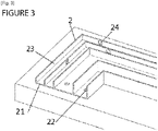
- the first fixing element 2 comprises at least a first part 21 forming a base fixed to the support 4, said base having orifices 22.
- these orifices 22 present in the base allow both better evacuation of water while allowing better grip of the covering 5 to the first fixing element 2 by the passage of a part of said floor directly into the element of fixing by said orifices 22 of the base, and therefore a better grip.
- the base 21 comprises a heightening element 9, for example a washer placed under the base 21 before its attachment, or a thickness (not shown) present directly on the face of the base 21 in contact with the support, in order to raise said base, which advantageously makes it possible to facilitate the flow of water.
- the booster element 9 can for example and in a non-limiting manner have a thickness of 5 mm.
- a series of grooves for example 3 millimeters thick and 3 millimeters deep, is made to facilitate the flow of rainwater to the outside of the coating.
- the dimensions of these grooves vary according to the use case and the cited example is not limiting.
- the raising element can also be made in the form of a concrete flashing with a thickness of approximately 5 to 10 cm, placed under the entire base, on the periphery of the covering.
- this greatly facilitates the flow of water when the support is quite porous, for example in compacted gravel, the water then being able to flow through the coating and the support through the center of the covered zone, and the periphery of the coating resting on the concrete flashing.
- the coating 5 has damping properties and comprises at least one damping layer and an aesthetic layer 52 covering said damping layer, the fastening device 1 being at least embedded in the aesthetic layer 52 and/or the damping layer, and preferably both in the damping layer and in the aesthetic layer 52.
- the damping layer can be composed of shredded tires.
- the aesthetic layer 52 can also be damping.
- the aesthetic layer 52 can be composed of ground rubber, for example natural rubber.
- shredded tires have a particle size between 4 and 8mm. Independently, the ground rubber exhibits, for example, a particle size of between 1 and 4 mm.
- the dimensions of the diaper components generally have a grain size between 1mm to 8mm.
- the fixing device 1 is taken in the mass of the two layers.
- the components of the coating 5, for example rubber and/or tire aggregates, can pass through the meshes of the net and/or the expanded metal.
- the shredded materials are trapped in the meshes of the second fixing element 3, and it is then very difficult to dislodge the periphery, or border, of the coating 5 because it is caught, and hooked, in the fixing element.
- the first fastening element 2 has a second part 23 of which at least a portion forms a projection.
- the first fixing element 2 has a second part 23 extending away from the support 4, for example a wall having a non-zero angle with the support 4, preferably vertically with respect to the support 4. This allows the fixing device 1 to be better caught in the mass of the coating 5.
- this part has at least one aerial portion, facing the first part 21 of the first element, forming a base in contact with stand 4.
- the first fastening element 2 does not include a second part 23. It may only include a base 21 from which extends a second element 3, preferably forming a mesh.
- the portion forming a projection forms a right angle with the base of the first fixing element 2, in order to allow better gripping and a better distribution of the forces undergone during the use of the coating 5, by example by trampling.
- the protrusion-forming portion can form various structures suitable for better caking.
- the device is anchored to the support at the level of anchor points 7 present on the base 21.
- these anchor points are made on a part of the base 21 close to the periphery of the coating, rather than on a part more close to the center of the coating.
- the extending portion forms at least one angle.
- the extending portion forms a structure having straight walls formed by right angles.
- the right angles have sharp edges, but it is possible that they have chamfers.
- the presence of sharp edges can improve the grip in the mass of the device with the coating 5, by the distribution of the tensile forces, and by the increase in the contact and bonding surface.
- the first fixing element 2 further comprises orifices 24 in the second part 23 of the first fixing element 2, for example a wall having a non-zero angle with the support 4, for example a vertical wall.
- These orifices 24 can for example have a round, oval or oblong shape.
- the ground material can pass through the orifices 22, 24 of the base and of the wall of the first fixing element 2, the ground material then being trapped during their drying.
- this makes it possible to improve the effectiveness of caking with the coating 5 and therefore the fixing of the coating 5, without hindering the evacuation of water, the shredded material forming the different layers of the coating 5 being permeable to water. 'water.
- the second fixing element 3 which will be embedded in the mass in the coating 5 can be between approximately 7 and 15 cm depending on the thickness and the surface area of the coating 5 to be produced.
- the orifices 22 present on the base can for example be spaced apart by 10 cm.
- the first fastening element 2 forms at least one angle iron. This allows the floor to have an additional grip point formed by the vertical wall of the angle iron.
- the angle iron has a height of 3 cm, a width of 6 cm.
- first fixing elements each forming an angle iron it is possible to produce coverings 5 having the shapes of squares, rectangles, hexagonal and octagons.
- angles are nestable to make bends, for example 15°, 30°, 45°, 90°, incoming and/or outgoing angles.
- the first fixing element 2, for example forming an angle iron and the second fixing element 3, for example forming a mesh can be made in one piece.
- the mesh can be deployed at from the end of the base to then join the inclined wall, and continue beyond, towards the center of the coating 5.
- the two fixing elements are coupled by fixing means, for example screws or nails.
- the first fixing element 2 comprises a base forming a mesh in contact with the support 4.
- it can also comprise a second part 23 forming a mesh, and forming an inclined wall, the two parts being embedded in the coating 5.
- the first and second part are made of the same material, preferably in the same part.
- the first part 21 forming the base has a dimension between approximately 2 to 5 cm, preferably approximately 3 to 4 cm, this dimension being able to vary according to the thickness of the covering 5 to be fixed. This may include grooves 8 or thicknesses to respectively improve water evacuation or rigidity.
- the second part 23 forming the net has a length of between approximately 7 cm and 18 cm, the length being able to vary according to the thickness of the covering 5 to be fixed.
- the notches thus made in the mesh allow the borders to follow any profile, shape or angle.
- the notches can for example be spaced 15cm from each other on the base in contact with the support 4 and being adapted according to the configuration of the desired shapes.
- this type of fixing device 1 allows the realization of all possible shapes by bending and rounding of the net, including at the level of the angle between the base and the portion forming a projection, in other words the part Aerial.
- a multitude of possibilities at the level of the angle between the base and the aerial part is possible depending on the final thickness desired for the coating 5 as illustrated, by way of example, in figure 8 .
- the first fastening element 2 is formed of several angles. These angles each have a second part 23 of which at least one portion forms a projection, that is to say aerial parts, which can have the same height, or on the contrary have different dimensions.
- the fixing device 1 comprises only the first fixing element 2, without thread, and is formed of 5 vertical walls connected by a base in 4 parts.
- the number of vertical walls may vary depending on the embodiments. Increasing the number of vertical walls makes it possible to increase the number of attachment points and thus improve the fixing and the durability of the covering 5 on the support 4 and on the fixing device 1.
- the angles close to the center of the covering 5 each have a portion forming a higher projection than that of the angles further from the center, and therefore closer to the periphery or edge of the covering 5.
- the vertical walls close to the edge of coating 5 have lower heights than the vertical walls close to the center of coating 5.
- the height of the walls is defined by the height of the coating 5, and must not exceed half the height of said coating 5.
- they preferably measure a maximum of 1 cm in height in order to facilitate access to the playground and not represent an obstacle.
- the highest wall cannot exceed half the height of the final coating.
- the bends formed between two angles can have angles between 15° and 90° in order to adapt to different configurations of desired shapes.
- the angles have an "L" shape, in order to form vertical walls offering an optimal contact surface with the coating 5.
- orifices 22 are present over the entire first part 21 forming the base in order to guarantee the evacuation of water. These orifices 22 are preferably between 4 and 8 mm, preferably 6 mm.
- the aggregates of the shredded material stick to the walls of the compartments as illustrated in figure 4 .
- the bonding surface is therefore larger.
- the presence of the largest wall, being the wall closest to the center of the coating 5, therefore prevents the detachment of the aggregates during trampling, the pressure being exerted mainly from the top downwards.
- the fixing device 1 comprises a first fixing element 2, without thread, but with a first and a second part 23.
- the fixing element has the shape of an elongated "H", in other words a structure having straight walls, formed by right angles, and which has orifices 22, 24 allowing better evacuation of water and better maintenance of the layers of the coating 5.
- the fixing device 1 is made of extruded recycled plastic.
- this makes it possible to reduce the environmental impact, thanks to a very versatile material for the production of shapes because it is very flexible and solid at the same time.
- this material presents less risk of cuts in the event of exposure of the fastening device 1, and cannot rust, unlike certain metals.
- the material being flexible it is possible to make all shapes, however it is also possible to provide inward and/or outward angles of 15° to 90° to make the binding more versatile.
- the second part 23 of the first fixing element 2 forming a projection may comprise a vertical part and a horizontal part, the two parts possibly having orifices 24 allowing better evacuation of water and better maintenance of the adhesion of the layers of the coating 5 Grooves 8, for example in the direction of the width, can be made during manufacture under the base, first part 21 of the first element fixed to the support 4, in order to further promote the evacuation of water.
- the dimensions of the first fixing element 2 have a height of approximately 20mm, a width of the high horizontal wall of approximately 25mm, a width at the level of the base of approximately 35 to 45mm .
- the first fixing element 2 can also have holes 22 of approximately 10mm, approximately every 5 cm and holes 24 on the vertical wall of approximately 10mm ⁇ 30mm, approximately every 5 cm in order to ensure a better grip in the mass.
- the fastening system comprises a first fastening element 2 formed for example of plastic which can be recycled, molded and/or extruded, and a second fastening element 3 forming a mesh, for example a fiberglass net.
- the first element 2, for example made of recycled plastic comprises a first part 21 composed of a wall forming a base in contact and fixed with the support 4 and does not comprise a second part 23.
- the second fixing element 3 can be present on the whole of the base 21 or only on a part, as represented in the figure 6 .
- the wall of the first fixing element 2 has a rounded outer edge.
- this facilitates access to the playground by presenting a height at the periphery of the coating 5 that is zero or almost zero in order to reduce the risk of tripping for a young user.
- the wall has a thickness of about 5 mm which includes orifices 24, preferably 10, 20 or 30 mm in order to increase the hooking and bonding surface.
- orifices 24 promote the evacuation of rainwater and at the same time increase the gripping surface of the covering 5 in order to ensure optimum bonding.
- This type of invisible edging fastener is ideal for small thicknesses of flooring 5, and it is easy to cut it to the desired degree to achieve any desired shape.
- the fiberglass mesh has meshes whose size is between 6mm and 25mm.
- the fiberglass net can be molded to the first fixing element 2, and has a length of between about 12 and 15 cm depending on the thickness of the coating 5.
- the meshes of the fiberglass mesh as well as the perforations of the part in contact with the ground trap the aggregates and form a single part, making the detachment of the aggregates very difficult or almost impossible in normal use.
- the mesh is placed halfway between the top of the covering 5 and the support 4 in order to ensure optimum maintenance of the edges of the covering 5, which has the additional advantage for the mesh of not be in contact with the support 4.
- the mesh is thus protected against damage due to frost, even when there is stagnant water present at the level of the support surface 4.
- the figure 7 represents a coating device 5 comprising a first and a second fastening element 3, once said coating 5 has been deposited on the fastening device 1 and fixed to the support 4 by the latter.
- the two layers of the coating 5 both take the two fixing elements in the mass.
- the fixing device 1 is fixed by anchoring the base of the first fixing element 2 directly to the support 4 by anchoring means chosen from bolting, chemical or conventional anchors, for example at part of the orifices 22 of said base.
- the spitage is used in the case of a concrete support 4, while the fixing by chemical anchor is used in the case of a coated support 4.
- the deposition of the glue layer is generally carried out by using a glue roller.
- the deposition of glue at least at the edges and therefore at the level of the first fixing element 2, is carried out by a pressure gun, such as a glue gun, for more precision, and for a more even spread over the entire surface to be bonded.
- the fixing of the first fixing element 2 to the support 4 carried out by a bolt or by a chemical anchor according to the support 4, can be raised by 2 to 3 mm to promote the flow and the evacuation of the water, so that freezing standing water does not damage the system.
- the device makes it possible to fix a coating on a bare support, but can also be used in situations of restoration of a coating in poor condition, peeled off for example.
- a coating is present before the installation of a device, for example in the case of a restoration of a detached coating, it is possible to cut and/or remove only the edges of the coating, in order to to access the support at its edges.
- the device is then fixed and then covered with the coating in order to be solidified therein.
- the coating can thus be deposited and glued only at the level of the edges to be replaced, leaving the center of the coating intact, still in good condition. This has the advantage of reducing the amount of materials used for a restoration, concentrating on the restoration and fixing of the more fragile edges.
- the edges are then fixed firmly and durably, thanks to the device.
- the installer For installation, the installer provides the thickness of the coating 5 according to the potential fall height of the installed equipment.
- the glue is deposited by a pressure gun at least on the fixing device 1.
- the coating 5 comprises at least one damping layer (51) and an aesthetic layer 52 covering the damping layer, and where, following the mixing of its components of each layer with glue, the damping layer is deposited on at least the support 4, and preferably on at least a part of the fixing device 1, then the aesthetic layer 52 is deposited on at least the damping layer and preferably on at least a part of the fixing device 1.
- the deposition is carried out so that the fixing device 1 is taken in the mass of the two layers.
- the user's potential fall height differs depending on the more or less high coating thickness 5 chosen.
- an aluminum expanded metal about 1 centimeter in height for example. After pouring the coating aggregates and drying, the coating is held together by the expanded metal. In this configuration, it is no longer necessary to use a bonding primer or a layer of polyurethane adhesive, usually applied before casting the aggregates, which is an environmental advantage.
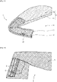
- the present invention also relates to a method for repairing a covering device 5 of a support 4 by means of a fixing device 1 comprising at least a first fixing element 2.
- This repair method is for example implemented when an existing coating device 5 suffers damage and peels off on its periphery. However, this method can also be implemented when carrying out the fixing of a new coating 5 on a support 4.
- the method comprises a step of exposing the support 4 on the parts of the coating device 5 that need to be repaired. For a detachment at the edge of the coating, it is thus necessary to cut the part of the coating which is peeling off in order to remove it and have access to the underlying support 4.
- the method comprises the production of a first fastening element 2 along the length of the covering device 5 to be repaired, by producing a longitudinal slot 10 .
- This can, for example, be made in the support 4 or in an added edge 11 fixed to the support 4.
- the slot 10 can be made in a support 4 when the latter is for example made of concrete, asphalt, asphalt, wood or any other material in which a slot 10 can be produced.
- a slot 10 can be made in an added curb 11, when the latter is for example made of concrete curbs of type P1 or P2, asphalt, asphalt, wood or any other hard material in which a slot 10 can be made.
- Coated and asphalt are, for example, materials chosen so that the border 11 has a specific geometric shape at the location where this border 11 is positioned.
- this is a section made of recycled plastic, aluminum or any other material suitable for making a profile.
- the use of a profile makes it possible, for example, to make the slot 10 during the manufacture of said profile rather than making it a posteriori with a router.
- the slot 10 is for example placed on its upper part 12 or on its side part 13.
- the slot 10 is made for example with a trapezoidal shape of the "dovetail” type, the shape of an inverted “T", a "U” slightly closed or straight on its upper part, or else all another form requiring the production of a slot 10 with a narrowed upper part and a lower part of increased size.
- the slot 10 has for example a depth of a few centimeters, for example 2 centimeters and has for example a width of a size ranging from a few millimeters to a few centimeters.
- the depth of the slot 10 requires a depth of the material in which the slot 10 is present at least greater than the depth of the slot 10, for example 4 centimeters if the slot 10 is 2 centimeters deep.
- the slots can be made in all shapes, all depths and all possible widths depending on the configuration, the height of the floors or the nature of the supports.
- the method according to the first embodiment also comprises a step of inserting a second fixing element 3 into the slot 10.
- a mesh 3 which extends from the slot 10 towards the center coating 5. It has for example a width of more than twenty centimeters.
- This is, for example, a fiberglass net, a polypropylene mesh, an aluminum expanded metal or a perforated sheet.
- the mesh 3 makes it possible to maintain the coating 5 once in place thanks to its honeycomb shape.
- a fixing mixture 14 contains, for example, epoxy adhesive, or a chemical sealant or any other sealing material, or even, depending on its dimensions, rubber mixed with polyurethane glue and fiberglass flakes.
- the coating 5 is cast on the support 4 to be coated as well as above and below the mesh 3 and the slot 10. It comprises a damping lower layer 51 and an aesthetic upper layer 52 composed for example of Diene Monomer, polyurethane glue and fiberglass flakes.
- the mesh 3 is taken in the coating 5, for example between the two layers or in one of the two layers.
- a layer of glue 15 mixed with fiberglass flakes is applied to the old coating 16 in order to solidify the joint between the old 16 and the new coating 5, visible figure 10 .
- the fixing device 1 obtained between the mesh 3 and the aggregates present in the slot 10 is taken in the mass of the covering 5 and makes it possible to fix the covering 5 to the support 4.
- the slot is replaced by a succession of holes, the bottom of the hole of which is wider than the top in order to be able to insert pieces of mesh and the coating therein so that, after drying, the coating is fixed to the support by this device taken in its mass.
- the holes are drilled in the support or in an added border and have a frustoconical shape.
- the mesh pieces have for example a size of about 10 centimeters long, depending on the thickness of the coating, and a few centimeters wide.
- the coating is for example a mixture of aggregates and fiberglass flakes.
- the first fixing element 2 is directly fixed to the support 4. It is for example a set of chemical plugs, plastic or brass, nails, screws or other fixing elements. These first fixing elements 2 are placed over the entire length of the covering device 5 to be repaired and are spaced apart, for example, by about fifteen centimeters.
- the method according to the second mode of implementation also comprises a step of inserting a second fixing element 3 fixed between the support 4 and the first fixing element 2.
- a mesh 3 which extends from the first fastening element 2 towards the center of the coating 5. It has for example a width of more than twenty centimeters.
- These are, for example, a fiberglass net, a polypropylene mesh, an aluminum expanded metal or perforated sheet.
- the mesh 3 makes it possible to maintain the coating 5 once in place thanks to its honeycomb shape.
- the coating 5 is then cast on the support 4 to be coated as well as over the mesh 3 and the first fixing element 2. It comprises a damping lower layer 51 and an aesthetic upper layer 52 composed for example of Ethylene-Propylene- Diene Monomer, polyurethane glue and fiberglass flakes.
- the color of the new aesthetic layer 52 is for example different from the original color of the old coating 16 in order to indicate that the latter has been repaired.
- Mesh 3 is taken from covering 5, by example between the two layers or in one of the two layers. Beforehand, a layer of polyurethane glue 15 mixed with fiberglass flakes is applied to the old covering 16 in order to durably solidify the joint between the old 16 and the new covering 5.
- the fixing device 1 obtained between the mesh 3 and the first fixing element 2 is taken in the mass of the covering 5 and makes it possible to fix the covering 5 to the support 4.
- the first fixing element 2 is an aluminum tube with a square or round section and a diameter of between 5 and 15 millimeters depending on the final thickness of the coating 5.
- Aluminum is easily moldable and makes it possible to create any shape of covering periphery 5. It is fixed to the support 4 using fixing lugs 17 arranged at variable distances, for example nailed or screwed to the support.
- a fiberglass mesh 3 is fixed between the aluminum tube 2 and the support 4, which makes it possible to cover this fixing device 1 with the coating 5 with a thin coating.
- the mesh is in particular taken in the mass of the coating on its upper side and on its lower side, the coating being fixed vis-à-vis the latter since passing through the meshes of the mesh.
- the first fixing element 2 is for example a rail or a thin aluminum border fixed to the support.
- a mesh is fixed between the rail and the support and extends inwards.
- a step of covering this fixing device is then carried out with the pouring of the covering.
- the first fixing element 2 is for example a rail or a thin plastic border fixed to the support.
- a mesh is fixed between the rail and the support and extends inwards.
- a step of covering this fixing device is then carried out with the pouring of the covering.
Description
La présente invention concerne de manière générale le domaine des revêtements de surface, en particulier les dispositifs de fixations de revêtements de sols, en particulier les sols amortissants tels que les sols d'aires de jeux. En particulier un système de fixation de la périphérie de tels revêtements.The present invention relates generally to the field of surface coverings, in particular to floor covering fixing devices, in particular to damping floors such as playground floors. In particular a system for fixing the periphery of such coatings.
La présente invention concerne également un procédé permettant de réparer les périphéries d'un revêtement d'une surface support.The present invention also relates to a method for repairing the peripheries of a coating of a support surface.
Il est connu le problème du décollement de revêtements et de sols amortissants à leur périphérie. En effet la bordure des sols amortissants, par exemple des sols amortissants d'aires de jeux, présentent une fragilité plus importante et une tendance à se décoller ou à s'arracher suite aux piétinements répétés des utilisateurs ; aux variations de températures ; à la stagnation des eaux pluviales due à l'irrégularité de niveaux des supports ; aux balayeuses mécaniques au sein des cours d'écoles etc.The problem of detachment of coverings and damping floors at their periphery is known. In fact, the edges of damping floors, for example damping floors of play areas, have greater fragility and a tendency to peel off or tear off following repeated trampling by users; temperature variations; the stagnation of rainwater due to the irregularity of the levels of the supports; mechanical sweepers in schoolyards etc.
Par ailleurs, les revêtements de sols peuvent être utilisés pour diverses applications ludiques, sportives, telles que les pistes d'athlétisme, les terrains de jeux, l'équitation, et également dans des ouvrages de voiries et réseaux divers, pour la réparation des cavités sur les chaussées en asphalte, appelées nids de poules, par exemple. Dans ces cas, les modes opératoires sont adaptés selon le domaine d'intervention.Furthermore, the floor coverings can be used for various recreational and sporting applications, such as athletics tracks, playgrounds, horse riding, and also in road works and various networks, for the repair of cavities. on asphalt pavements, called potholes, for example. In these cases, the operating methods are adapted according to the field of intervention.
Il existe diverses solutions pour fixer les revêtements de sol, et en particulier pour fixer les sols amortissants.There are various solutions for fixing floor coverings, and in particular for fixing shock-absorbing floors.
Une première solution est de coller le revêtement amortissant à même le sol faisant office de support, le sol étant en général en enrobé, ou en béton. Cela nécessite de grosses quantités de colle et la périphérie de ces sols demeure fragile et sensible au décollement, pour les raisons évoquées précédemment.A first solution is to glue the damping coating directly to the ground acting as a support, the ground generally being asphalt or concrete. This requires large quantities of glue and the periphery of these floors remains fragile and sensitive to detachment, for the reasons mentioned above.
Une autre solution est de réaliser une longrine, aussi appelée tranchée, qui consiste en la réalisation d'une tranchée, ou tunnel ouvert, d'environ 10 cm sur 10 cm de largeur sur 10 cm de profondeur sur tout le contour du support sur lequel doit être posé le revêtement. Une quantité plus importante de granulats est utilisée dans cette solution, mais les bordures restent sensibles à l'arrachement. Ledit revêtement est coulé et/ou déposé sur le support et dans les longrines afin d'avoir une résistance plus importante à l'arrachement au niveau de ces bordures car bénéficiant d'une épaisseur plus élevée dans ces zones. Cela présente cependant l'inconvénient d'endommager le support situé sous le revêtement, car les longrines creusées sont nécessaires, et sont réalisées directement dans le support. De plus, si le revêtement est retiré ou modifié, il faudra aussi remettre en état et/ou recreuser le support avant de pouvoir le réutiliser. Ainsi la remise en état du support reste à charge de l'exploitant, celle-ci représentant un coût très important.Another solution is to make a sill, also called a trench, which consists of making a trench, or open tunnel, approximately 10 cm by 10 cm wide by 10 cm deep over the entire contour of the support on which the coating must be laid. A larger quantity of aggregates is used in this solution, but the edges remain sensitive to tearing. Said coating is poured and/or deposited on the support and in the stringers in order to have a greater resistance to tearing at the level of these edges because it benefits from a greater thickness in these areas. However, this has the disadvantage of damaging the support located under the coating, because hollow stringers are necessary, and are made directly in the support. In addition, if the coating is removed or modified, it will also be necessary to restore and/or regroove the support before it can be used again. Thus the restoration of the support remains the responsibility of the operator, this representing a very significant cost.
Une autre solution consiste en la réalisation d'une dalle béton d'environ 10 à 15cm d'épaisseur sur toute la surface à couvrir et en périphérie une assise pour les bordures en béton de 20 cm de haut, de 8 cm de large et d'au moins 1 m de long. Ainsi, le niveau de ladite dalle est maîtrisé, ce qui simplifie une bonne évacuation des eaux pluviales. De plus, les parties supérieures de ces bordures sont arrondies et présentent une rugosité ce qui permet d'améliorer l'adhérence du revêtement avec la bordure, lorsque ledit revêtement est coulé. Cependant, cette solution présente comme inconvénient la nécessaire réalisation d'un support spécifique réalisé dans ce but, ce qui demande un investissement considérable en temps et en argent. En cas de remise en état de l'installation, l'exploitant doit prendre en charge la remise en état du support initial ou son remplacement.Another solution consists in making a concrete slab about 10 to 15cm thick over the entire surface to be covered and on the periphery a foundation for the concrete curbs 20 cm high, 8 cm wide and thick. at least 1 m long. Thus, the level of said slab is controlled, which simplifies good drainage of rainwater. In addition, the upper parts of these borders are rounded and have a roughness which makes it possible to improve the adhesion of the coating with the border, when said coating is poured. However, this solution has the disadvantage of the necessary production of a specific support made for this purpose, which requires a considerable investment of time and money. If the installation is repaired, the operator must pay for the repair of the initial support or its replacement.
Une autre solution existante consiste en l'utilisation de bordures caoutchouc. Ces bordures sont réalisées, à l'instar de celles en béton, directement sur une assise en béton. Cette solution nécessite cependant elle aussi un investissement financier important, ainsi qu'un temps de réalisation important.Another existing solution consists of the use of rubber borders. These curbs are made, like those in concrete, directly on a concrete base. However, this solution also requires a significant financial investment, as well as a significant time for completion.
Toutes ces solutions, coûteuses, posent des problèmes de durabilité, de coûts élevés d'entretien, ainsi que des problèmes environnementaux. En termes de durabilité, les gestionnaires sont en général contraints d'intervenir 6 à 8 ans après installation du revêtement pour une mise en conformité de celui-ci due au décollement des périphéries du revêtement, ce qui génère un coût important, et des problèmes de sécurité pour les utilisateurs des équipements. En termes environnementaux, la réalisation et l'installation de tels revêtements produit beaucoup de déchets, notamment lors de l'intervention de remise en état, les sols amortissants en bordure étant coupés et mises en déchetterie, et lors de l'utilisation importante de colle pour la couche d'accrochage en périphérie afin que les bordures puissent tenir le plus longtemps possible. La réalisation, et la réparation de supports présentent elles aussi des coûts financiers et environnementaux élevés.All these costly solutions pose problems of durability, high maintenance costs, as well as environmental problems. In terms of durability, managers are generally forced to intervene 6 to 8 years after installation of the coating to bring it into conformity due to the detachment of the peripheries of the coating, which generates a significant cost, and problems of safety for equipment users. In environmental terms, the production and installation of such coatings produces a lot of waste, especially during the restoration intervention, the damping floors on the edge being cut and put in the dump, and during the significant use of glue. for the adhesion layer on the periphery so that the edges can hold as long as possible. The construction and repair of supports also have high financial and environmental costs.
En effet, face au phénomène de décollement des périphéries, ou bordures, la remise en état peut être réalisée de deux manières différentes. Une première possibilité consiste à couper et retirer la périphérie du revêtement au niveau du décollement, afin de la remplacer, ce qui génère des déchets, puis à réaliser une nouvelle périphérie, généralement d'une autre couleur, ce qui représente un coût important. La deuxième possibilité consiste à réaliser des surépaisseurs de revêtements au niveau de la périphérie, ce qui donne lieu à zones semis-bombées, susceptibles de représenter des obstacles pour les utilisateurs, qui peuvent par exemple trébucher dessus. Ce type de solution ne respecte d'ailleurs généralement pas les exigences des normes en vigueur à cause des problèmes de sécurité pour les utilisateurs.Indeed, faced with the phenomenon of detachment of the peripheries, or borders, the restoration can be carried out in two different ways. A first possibility consists in cutting and removing the periphery of the coating at the level of the detachment, in order to replace it, which generates waste, then in making a new periphery, generally of another color, which represents a significant cost. The second possibility consists in making extra thicknesses of coatings at the level of the periphery, which gives rise to semi-bulged zones, likely to represent obstacles for the users, who can for example stumble over them. This type of solution generally does not meet the requirements of the standards in force because of security problems for users.
Les documents
La présente invention a donc pour objet de proposer un dispositif de revêtement de sols, permettant de palier au moins une partie des inconvénients de l'art antérieur tout en proposant une solution peu coûteuse, invisible et facile à installer, réduisant les quantités de déchets et de produits chimiques utilisés notamment pour la fixation du revêtement, tout en étant adaptée à une grande diversité de supports, sans avoir besoin de les modifier, et ce durant toute la durée de vie du sol amortissant.The object of the present invention is therefore to provide a floor covering device, making it possible to overcome at least some of the drawbacks of the prior art while providing an inexpensive, invisible and easy to install solution, reducing the quantities of waste and chemical products used in particular for fixing the coating, while being suitable for a large diversity of substrates, without the need to modify them, and this throughout the life of the damping floor.
De plus, l'invention permet d'éviter les remises en état du revêtement car le système garantit le maintien des périphéries sur toute sa durée de vie compte tenu de la qualité des matériaux tels que l'acier inoxydable, le laiton, l'aluminium, le plastique recyclé et des maillages en fibre de verre. Ceci représente un gain financier puisque les périphéries desdits revêtements sont actuellement reprises jusqu'à trois fois durant leur vie.In addition, the invention makes it possible to avoid repairs to the coating because the system guarantees the maintenance of the peripheries over its entire life, taking into account the quality of the materials such as stainless steel, brass, aluminum , recycled plastic and fiberglass mesh. This represents a financial gain since the peripheries of said coatings are currently covered up to three times during their life.
Cette solution a aussi pour but de ne pas avoir à creuser le support sur lequel sera déposée le revêtement et à ce que le système de fixation ne dépasse pas du revêtement mais est intégré dans celui-ci.This solution also aims to avoid having to dig the support on which the coating will be deposited and so that the fixing system does not protrude from the coating but is integrated into it.
A cet effet, l'invention concerne un dispositif de revêtement d'un support, ledit dispositif comprenant :
- un revêtement, préférentiellement amortissant, configuré pour recouvrir ledit support,
- un dispositif de fixation du revêtement sur le support, le dispositif de fixation comprenant au moins un premier élément de fixation configuré pour être fixé directement sur une surface dudit support par des moyens d'ancrage configurés en fonction de la nature du support, caractérisé et- en ce que le dispositif de fixation est complètement pris dans la masse dudit revêtement.
- a coating, preferably damping, configured to cover said support,
- a device for fixing the covering on the support, the fixing device comprising at least a first fixing element configured to be fixed directly to a surface of said support by anchoring means configured according to the nature of the support, characterized and- in that the fastening device is completely embedded in the mass of said coating.
Selon une particularité, le premier élément de fixation forme une bordure délimitant au moins une partie de la surface du support à recouvrir.According to one feature, the first fastening element forms a border delimiting at least a part of the surface of the support to be covered.
Selon une particularité, le premier élément de fixation est fixé uniquement sur la surface dudit support.According to one feature, the first fixing element is fixed only to the surface of said support.
Selon une particularité, le dispositif de fixation comprend en outre au moins un second élément de fixation couplé au premier élément de fixation et qui s'étend vers l'intérieur, préférentiellement le centre, du revêtement.According to one feature, the fastening device further comprises at least one second fastening element coupled to the first fastening element and which extends towards the inside, preferably the center, of the coating.
Selon une particularité, le second élément de fixation forme un maillage.According to one feature, the second fastening element forms a mesh.
Selon une particularité, le premier élément de fixation comprend au moins une première partie formant une base fixée au support, ladite base présentant des orifices.According to one feature, the first fixing element comprises at least a first part forming a base fixed to the support, said base having orifices.
Selon une particularité, le premier élément de fixation présente une seconde partie dont au moins une portion forme une saillie.According to one feature, the first fastening element has a second part, at least one portion of which forms a projection.
Selon une particularité, le dispositif de fixation est fixé par ancrage de la base du premier élément de fixation directement sur le support de préférence par des moyens d'ancrage choisis en fonction du support sur lequel le dispositif est fixé.According to one feature, the fixing device is fixed by anchoring the base of the first fixing element directly to the support, preferably by anchoring means chosen according to the support to which the device is fixed.
Selon une particularité, le revêtement possède des propriétés amortissantes et comprend au moins une couche amortissante et une couche esthétique recouvrant ladite couche amortissante, le dispositif de fixation étant au moins pris dans la masse de la couche esthétique et/ou la couche amortissante, et préférentiellement à la fois dans la couche amortissante et dans la couche esthétique.According to one feature, the coating has damping properties and comprises at least one damping layer and an aesthetic layer covering said damping layer, the fastening device being at least embedded in the mass of the aesthetic layer and/or the damping layer, and preferably both in the cushioning layer and in the aesthetic layer.
Selon une particularité, le dispositif de fixation comprend en outre des orifices dans la seconde partie du premier élément de fixation.According to one feature, the fastening device further comprises orifices in the second part of the first fastening element.
L'application concerne aussi le procédé non revendiqué de fixation d'un revêtement sur un support, grâce au dispositif de fixation selon l'invention.The application also relates to the unclaimed method of fixing a covering to a support, using the fixing device according to the invention.
Ce but est atteint, par un procédé de fixation d'un revêtement d'un support, sans nécessiter de creuser de tranchées dans ou autour dudit support, au moyen d'un dispositif de fixation comprenant au moins un premier élément de fixation, le procédé étant caractérisé en ce qu'il comprend les étapes suivantes :
- Dépôt du dispositif de fixation en bordure du support à recouvrir, ledit premier élément de fixation formant un périmètre délimitant ladite surface du support à recouvrir,
- Fixation du premier élément de fixation du système de fixation par des moyens d'ancrage configurés en fonction du support,
- Dépôt de colle sur au moins une partie du dispositif de fixation, de préférence sur tout le système de fixation,
- Mélange des composants du revêtement à de la colle, puis dépôt sur le dispositif de fixation et sur le support à recouvrir, de façon à ce que le revêtement recouvre entièrement le dispositif de fixation, le dispositif de fixation étant alors pris dans la masse du revêtement, puis repos/séchage.
- Deposition of the fixing device at the edge of the support to be covered, said first fixing element forming a perimeter delimiting said surface of the support to be covered,
- Fixing of the first fixing element of the fixing system by anchoring means configured according to the support,
- Deposition of glue on at least part of the fixing device, preferably on the entire fixing system,
- Mixing of the components of the coating with glue, then depositing on the fixing device and on the support to be covered, so that the coating completely covers the fixing device, the fixing device then being taken in the mass of the coating , then rest/dry.
Selon une particularité, dans le procédé non revendiqué, les moyens d'ancrage sont réalisés par spitage sur la surface du support lorsque ledit support est composé de béton ou par cheville chimique sur la surface du support lorsque ledit support est composé d'enrobé.According to one feature, in the method not claimed, the anchoring means are made by bolting onto the surface of the support when said support is made of concrete or by chemical dowel on the surface of the support when said support is made of asphalt.
Selon une particularité, dans le procédé non revendiqué, le revêtement comprend au moins une couche amortissante et une couche esthétique recouvrant la couche amortissante, et où, suite au mélange de ses composants de chaque couche avec de la colle, la couche amortissante est déposée sur au moins le support, et de préférence sur au moins une partie du dispositif de fixation, puis la couche esthétique est déposée sur au moins la couche amortissante et de préférence sur au moins une partie du dispositif de fixationAccording to one feature, in the method not claimed, the coating comprises at least one damping layer and an aesthetic layer covering the damping layer, and where, following the mixing of its components of each layer with glue, the damping layer is deposited on at least the support, and preferably on at least part of the fixing device, then the aesthetic layer is deposited on at least the damping layer and preferably on at least part of the fixing device
L'objet de l'invention concerne également un procédé de réparation d'un dispositif de revêtement d'un support comprenant un revêtement, préférentiellement amortissant, configuré pour recouvrir ledit support, un dispositif de fixation du revêtement sur le support, comprenant au moins un premier élément de fixation configuré pour être fixé directement sur une surface dudit support par des moyens d'ancrage configurés en fonction de la nature du support, le dispositif de fixation étant complètement pris dans la masse dudit revêtement. Le procédé comprend les étapes suivantes :
- Mise à nu du support sur la partie à réparer ;
- Mise en place et fixation du dispositif de fixation au moins en bordure de la partie du support à recouvrir ;
- Dépôt de colle sur la partie de l'ancien revêtement destinée à être en contact avec le nouveau revêtement ;
- Mélange des composants du revêtement à de la colle, puis dépôt sur le dispositif de fixation et sur la partie du support à recouvrir, de façon à ce que le revêtement recouvre entièrement le dispositif de fixation, le dispositif de fixation étant alors pris dans la masse du revêtement ; et
- Séchage du revêtement.
- Exposing the support on the part to be repaired;
- Installation and fixing of the fixing device at least on the edge of the part of the support to be covered;
- Deposit of glue on the part of the old coating intended to be in contact with the new coating;
- Mixing of the components of the coating with glue, then depositing on the fixing device and on the part of the support to be covered, so that the coating entirely covers the fastening device, the fastening device then being taken up in the mass of the coating; and
- Coating drying.
Selon un mode de mise en œuvre du procédé de réparation, le premier élément de fixation est une fente pratiquée dans le support ou pratiquée dans une bordure rapportée fixée au support.According to one mode of implementation of the repair method, the first fastening element is a slot made in the support or made in an added edge fixed to the support.
Selon un autre mode de mise en œuvre du procédé de réparation, le premier élément de fixation est fixé uniquement sur la surface du support.According to another mode of implementation of the repair method, the first fastening element is fixed only to the surface of the support.
Avantageusement, dans un mode de mise en œuvre du procédé, le dispositif de fixation comprend en outre au moins un second élément de fixation couplé au premier élément de fixation et qui s'étend vers l'intérieur, préférentiellement le centre, du revêtement.Advantageously, in one embodiment of the method, the fastening device further comprises at least one second fastening element coupled to the first fastening element and which extends towards the inside, preferably the center, of the covering.
Avantageusement, le second élément de fixation (3) forme un maillage.Advantageously, the second fixing element (3) forms a mesh.
D'autres caractéristiques, détails et avantages de l'invention ressortiront à la lecture de la description qui suit en référence aux figures annexées, qui illustre :
- [
Fig. 1 ] représente une vue schématique d'une partie d'un premier mode de réalisation de l'invention. - [
Fig. 2 ] représente une vue schématique d'une partie d'un second mode de réalisation de l'invention - [
Fig. 3 ] représente une vue schématique d'une partie d'un troisième mode de réalisation de l'invention - [
Fig. 4 ] représente une vue du dessus d'un troisième mode de réalisation de l'invention - [
Fig. 5 ] représente une vue schématique d'une partie d'un quatrième mode de réalisation de l'invention - [
Fig. 6 ] représente une vue schématique d'une partie d'un cinquième mode de réalisation de l'invention - [
Fig. 7 ] représente une vue schématique en vue de coupe du premier mode de réalisation de l'invention. - [
Fig. 8 ] représente schématiquement plusieurs possibilités d'inclinaison et de longueur du deuxième mode de réalisation. - [
Fig. 9 ] représente schématiquement en vue de coupe un premier mode de réalisation d'un dispositif de revêtement réparé selon l'invention. - [
Fig. 10 ] représente schématiquement un second mode de réalisation d'un dispositif de revêtement réparé selon l'invention. - [
Fig. 11 ] représente schématiquement une variante du second mode de réalisation d'un dispositif de revêtement réparé selon l'invention. - [
Fig. 12 ] représente schématiquement une seconde variante du second mode de réalisation d'un dispositif de revêtement réparé selon l'invention. - [
Fig. 13 ] représente schématiquement une troisième variante du second mode de réalisation d'un dispositif de revêtement réparé selon l'invention.
- [
Fig. 1 ] shows a schematic view of part of a first embodiment of the invention. - [
Fig. 2 ] shows a schematic view of part of a second embodiment of the invention - [
Fig. 3 ] shows a schematic view of part of a third embodiment of the invention - [
Fig. 4 ] shows a top view of a third embodiment of the invention - [
Fig. 5 ] shows a schematic view of part of a fourth embodiment of the invention - [
Fig. 6 ] shows a schematic view of part of a fifth embodiment of the invention - [
Fig. 7 ] shows a schematic sectional view of the first embodiment of the invention. - [
Fig. 8 ] schematically represents several possibilities of inclination and length of the second embodiment. - [
Fig. 9 ] schematically shows in sectional view a first embodiment of a repaired coating device according to the invention. - [
Fig. 10 ] schematically represents a second embodiment of a repaired coating device according to the invention. - [
Fig. 11 ] schematically represents a variant of the second embodiment of a repaired coating device according to the invention. - [
Fig. 12 ] schematically represents a second variant of the second embodiment of a repaired coating device according to the invention. - [
Fig. 13 ] schematically represents a third variant of the second embodiment of a repaired coating device according to the invention.
De nombreuses combinaisons peuvent être envisagées sans sortir du cadre de l'invention ; l'homme de métier choisira l'une ou l'autre en fonction des contraintes économiques, ergonomiques, dimensionnelles ou autres qu'il devra respecter.Many combinations can be envisaged without departing from the scope of the invention; the person skilled in the art will choose one or the other depending on the economic, ergonomic, dimensional or other constraints that he will have to respect.
Par « spitage » on en entend le fait de spiter, ou encore de pisto-sceller, c'est-à-dire par exemple l'utilisation d'un pistolet à gaz et/ou à batterie capable de planter des clous dans de l'acier, du béton et d'autres supports 4 durs.By "spitage" we mean the fact of spiter, or even of gun-seal, that is to say for example the use of a gas gun and / or battery capable of driving nails into the 4 steel, concrete and other hard substrates.
Par « cheville chimique » on entend le dépôt d'une résine bi-matière dont la réaction va provoquer une solidification de ladite résine et la fixation de celle-ci au support 4.By "chemical anchor" is meant the deposition of a bi-material resin, the reaction of which will cause the said resin to solidify and the latter to be fixed to the
Par « filet », on entend tout quadrillage, ensemble de mailles qui peuvent présenter une forme ronde, carrée, de losange ou encore rectangulaire configurée pour permettre une répartition des forces d'adhésion et des pressions subies lors de l'utilisation du revêtement 5, une fois la prise en masse du filet par une couche du sol réalisée.By "net" is meant any grid, set of meshes which may have a round, square, diamond or even rectangular shape configured to allow a distribution of the adhesion forces and the pressures undergone during the use of the
Par revêtement 5 ou sol « amortissant », on entend un sol dont les propriétés permettent de réduire l'impact d'une chute, par exemple dans le cadre d'aires de jeux, où les utilisateurs, le plus souvent des enfants, sont susceptibles de tomber fréquemment.By coating 5 or "shock-absorbing" floor, is meant a floor whose properties make it possible to reduce the impact of a fall, for example in the context of playgrounds, where the users, most often children, are likely to fall frequently.
De manière générale, la présente invention comporte un dispositif de revêtement 5 d'une surface d'un support 4, ledit dispositif comprenant :
un revêtement 5, préférentiellement amortissant, configuré pour recouvrir leditsupport 4- un dispositif de
fixation 1 du revêtement 5 sur lesupport 4, le dispositif defixation 1 comprenant au moins un premier élément defixation 2 configuré pour être fixé directement sur unesurface dudit support 4 par des moyens d'ancrage configurés en fonction de la nature dusupport 4.
- a
coating 5, preferably damping, configured to cover saidsupport 4 - a
device 1 for fixing thecovering 5 on thesupport 4, the fixingdevice 1 comprising at least afirst fixing element 2 configured to be fixed directly on a surface of the saidsupport 4 by anchoring means configured according to the nature ofbracket 4.
Avantageusement, le revêtement 5 est alors fixé au support 4 sans que celui-ci est besoin d'être creusé et modifié.Advantageously, the
Selon l'invention, le dispositif de fixation 1 est complètement pris dans la masse dans ledit revêtement 5.According to the invention, the fixing
Cela permet au système de fixation de ne pas être visible tout en permettant une excellente fixation avec le revêtement 5 et avec le support, capable de durer dans le temps 4. Le système de fixation est ainsi invisible pour l'utilisateur. De préférence, il ne modifie pas significativement les capacités amortissantes du sol, compte tenu que ce système est installé en périphérie, et donc en dehors de la zone d'impact, ou zone de chute potentielle, définie lors de la conception de la zone à recouvrir par le revêtement.This allows the fixing system not to be visible while allowing excellent fixing with the
Dans des modes de réalisation, le premier élément de fixation 2 forme une bordure délimitant au moins une partie de la surface du support 4 à recouvrir. Dans des modes de réalisations préférés non limitatifs, le premier élément de fixation 2 forme une bordure délimitant la totalité de la surface du support 4 à recouvrir.In some embodiments, the
Avantageusement, améliorer la fixation de la périphérie, ou bordure, du revêtement 5 permet d'améliorer la durabilité de l'ensemble tout en économisant la quantité de matière et de structure utilisée par rapport à une fixation uniforme de l'ensemble du revêtement 5. Cela permet d'améliorer l'efficacité de la fixation à la périphérie du revêtement 5. Ainsi, la fixation au support 4 nécessite moins de colle, car le revêtement 5 est intégré au système de fixation, la partie centrale du revêtement 5 nécessitant moins de colle car maintenue par son propre poids. De plus, les pressions exercées à l'arrachement étant en outre quasi-nulles en dehors de la périphérie.Advantageously, improving the fixing of the periphery, or border, of the
Dans certains modes de réalisation, le premier élément de fixation 2 est fixé uniquement sur la surface dudit support 4.In some embodiments, the
En d'autres termes, la fixation du premier élément de fixation 2 du dispositif sur le support 4 est réalisée sans creuser de tranchées/longrines dans ou autour du support 4.In other words, the fixing of the
En d'autres termes, le support 4 ne comporte pas de tranchées/longrines et est de préférence sensiblement plat.In other words, the
Avantageusement, cela permet de ne pas endommager le support 4 et de faciliter la mise en place et le remplacement du revêtement 5 et du système de fixation sans avoir à faire des travaux importants d'aménagement.Advantageously, this makes it possible not to damage the
Par « sensiblement » plat, on entend un support 4 généralement exempt de modifications importantes de sa surface, et qui malgré des potentiels aspérités et autres reliefs ne comprends pas de structure particulière telle qu'une tranchée réalisée dans le but d'y fixer un revêtement 5.By "substantially" flat is meant a
Dans certains modes de réalisation, comme illustré à titre d'exemple et de manière non limitative à la
Avantageusement, cela permet d'améliorer la cohésion du revêtement 5 sur l'élément de fixation en multipliant les points sur lesquelles les pressions s'appliquent lors de l'utilisation du revêtement 5. Ainsi, au lieu d'avoir une concentration des pressions d'arrachement subies par le premier élément de fixation 2 situé en bordure, lesdites pressions vont se répartir de manière plus égale sur l'ensemble du revêtement 5 et du dispositif.Advantageously, this makes it possible to improve the cohesion of the
Avantageusement, le second élément de fixation n'altère aucunement la fonction essentielle d'amortissement du revêtement, compte tenu de son épaisseur, de sa forme et de sa position.Advantageously, the second fastening element in no way alters the essential damping function of the coating, given its thickness, its shape and its position.
De plus, le dispositif présente l'avantage supplémentaire de ne pas, ou peu, être affecté par la pluie et le gel, car la fixation du revêtement 5 n'est pas réalisée directement sur le support 4, là où la pluie peut s'infiltrer, stagner et geler, endommageant et/ou détruisant ainsi ladite fixation des dispositifs de l'art antérieur. En effet, à l'inverse dans l'invention la fixation est due au revêtement 5 pris dans la masse du dispositif, en partie au niveau d'éléments du dispositif n'étant pas en contact avec le support 4 et n'étant donc pas, ou peu, en contact avec l'eau de manière prolongée.In addition, the device has the additional advantage of not being affected, or only slightly, by rain and frost, because the fixing of the
Néanmoins, même en étant en contact avec le support et même si l'eau stagne en dessous, le revêtement amortissant demeure maintenu grâce au système pris dans la masse du revêtement amortissant, les granulats pris dans la maille se charge du maintien, d'où l'économie d'utilisation de produits chimiques tel que la colle d'adhésion au support.Nevertheless, even being in contact with the support and even if the water stagnates below, the damping coating remains maintained thanks to the system taken in the mass of the damping coating, the aggregates taken in the mesh take care of the maintenance, hence savings in the use of chemicals such as adhesion glue to the support.
Dans certains modes de réalisation, le second élément de fixation 3 forme un maillage. Ainsi, le second élément de fixation 3 peut former un filet dont les mailles présentent une forme ronde, carrée, de losange, en nid d'abeille ou encore rectangulaire.In certain embodiments, the
Avantageusement, le maillage est configuré pour répartir les forces d'adhésion et de tension appliquées au revêtement 5 lors de son utilisation, une fois ledit maillage pris dans la masse dans ledit revêtement 5.Advantageously, the mesh is configured to distribute the adhesion and tension forces applied to the
Dans la
Avantageusement, le profil du maillage permet de modifier les interactions du second élément de fixation 3 pris dans la masse dans le revêtement 5 avec les forces appliqués sur ledit sol. La taille des mailles peut aussi varier, de préférence entre 5 et 75mm, préférentiellement entre 10mm et 30mm, encore préférentiellement 10 et 25mm.Advantageously, the profile of the mesh makes it possible to modify the interactions of the
Dans certains modes de réalisation, le premier élément de fixation 2 comprend au moins une première partie 21 formant une base fixée au support 4, ladite base présentant des orifices 22.In certain embodiments, the
Avantageusement, ces orifices 22 présents dans la base permettent à la fois une meilleure évacuation de l'eau tout en permettant une meilleure accroche du revêtement 5 au premier élément de fixation 2 par le passage d'une partie dudit sol directement dans l'élément de fixation par lesdits orifices 22 de la base, et donc une meilleure prise en masse.Advantageously, these
Dans certains modes de réalisation, la base 21 comprend un élément rehausseur 9, par exemple une rondelle placée sous la base 21 avant sa fixation, ou une épaisseur (non représentée) présente directement sur la face de la base 21 en contact avec le support, afin de surélever ladite base, ce qui permet avantageusement de faciliter l'écoulement de l'eau. L'élément rehausseur 9 peut par exemple et de manière non limitative présenter une épaisseur de 5mm.In certain embodiments, the
Dans une variante, une série de rainurage, par exemple de 3 millimètres d'épaisseur et 3 millimètres, de profondeur est réalisée afin de faciliter l'écoulement de l'eau pluviale vers l'extérieur du revêtement. Les dimensions de ces rainurage varient selon les cas d'utilisation et l'exemple cité n'est pas limitatif.Alternatively, a series of grooves, for example 3 millimeters thick and 3 millimeters deep, is made to facilitate the flow of rainwater to the outside of the coating. The dimensions of these grooves vary according to the use case and the cited example is not limiting.
Dans d'autres modes de réalisation, l'élément rehausseur peut aussi être réalisé sous forme de solin en béton d'une épaisseur d'environ 5 à 10 cm, disposé sous l'ensemble de la base, en périphérie du revêtement. Avantageusement, cela facilite grandement l'écoulement de l'eau lorsque le support est assez poreux, par exemple en grave compactée, l'eau pouvant alors s'écouler à travers le revêtement et le support par le centre de la zone recouverte, et la périphérie du revêtement étant en appui sur le solin en béton.In other embodiments, the raising element can also be made in the form of a concrete flashing with a thickness of approximately 5 to 10 cm, placed under the entire base, on the periphery of the covering. Advantageously, this greatly facilitates the flow of water when the support is quite porous, for example in compacted gravel, the water then being able to flow through the coating and the support through the center of the covered zone, and the periphery of the coating resting on the concrete flashing.
Dans certains modes de réalisation, le revêtement 5 possède des propriétés amortissantes et comprend au moins une couche amortissante et une couche esthétique 52 recouvrant ladite couche amortissante, le dispositif de fixation 1 étant au moins pris dans la masse dans la couche esthétique 52 et/ou la couche amortissante, et préférentiellement à la fois dans la couche amortissante et dans la couche esthétique 52. La couche amortissante peut être composée de broyats de pneus. La couche esthétique 52 peut aussi être amortissante. La couche esthétique 52 peut être composée de broyats de caoutchouc, par exemple de caoutchouc naturel. Par exemple, les broyats de pneus ont une granulométrie comprise entre 4 et 8mm. Indépendamment, les broyats de caoutchouc présentent par exemple une granulométrie comprise entre 1 et 4 mm. Les dimensions des composants des couches présentent généralement une granulométrie entre 1 mm à 8mm.In certain embodiments, the
Dans certains modes de réalisation préférés, le dispositif de fixation 1 est pris dans la masse des deux couches.In certain preferred embodiments, the fixing
Ainsi, les composants du revêtement 5, par exemple des granulats en caoutchouc et/ou de pneus peuvent passer au travers des mailles du filet ou/et du métal déployé. Après séchage des couches du revêtement 5, les broyats sont emprisonnés dans les mailles du second élément de fixation 3, et il est alors très difficile de déloger la périphérie, ou bordure, du revêtement 5 car elle est prise, et accrochée, dans l'élément de fixation.Thus, the components of the
Dans des modes de réalisation, le premier élément de fixation 2 présente une seconde partie 23 dont au moins une portion forme une saillie. En d'autres termes, le premier élément de fixation 2 présente une seconde partie 23 s'étend en s'éloignant du support 4, par exemple une paroi présentant un angle non nul avec le support 4, préférentiellement verticalement par rapport au support 4. Cela permet au dispositif de fixation 1 d'être mieux pris dans la masse du revêtement 5. En d'autres termes, cette partie présente au moins une portion aérienne, en regard de la première partie 21 du premier élément, formant une base en contact avec le support 4.In some embodiments, the
Dans d'autres modes de réalisation, le premier élément de fixation 2 ne comprend pas de seconde partie 23. Il peut ne comprendre qu'une base 21 depuis laquelle s'étend un second élément 3, de préférence formant maillage.In other embodiments, the
Dans des modes de réalisations préférés, la portion formant saillie forme un angle droit avec la base du premier élément de fixation 2, afin de permettre une meilleure prise en masse et une meilleure répartition des efforts subis lors de l'utilisation du revêtement 5, par exemple par piétinement.In preferred embodiments, the portion forming a projection forms a right angle with the base of the
Dans des modes de réalisations, la portion formant saillie peut former des structures variées adaptées à une meilleure prise en masse.In embodiments, the protrusion-forming portion can form various structures suitable for better caking.
Le dispositif est ancré au support au niveau de points d'ancrage 7 présents sur la base 21. De préférence, ces points d'ancrage sont réalisés sur une partie de la base 21 proche de la périphérie du revêtement, plutôt que sur une partie plus proche du centre du revêtement.The device is anchored to the support at the level of anchor points 7 present on the
Dans des modes de réalisation, tels qu'illustrés par exemple et de manière non limitative à la
Dans des modes de réalisation, tels qu'illustrés par exemple et de manière non limitative à la
Préférentiellement les angles droits présentent des arêtes vives, mais il est envisageable qu'ils présentent des chanfreins. La présence d'arêtes vives peut améliorer la prise dans la masse du dispositif avec le revêtement 5, de par la répartition des forces de tension, et par l'augmentation de la surface de contact et de collage.Preferably the right angles have sharp edges, but it is possible that they have chamfers. The presence of sharp edges can improve the grip in the mass of the device with the
Dans des modes de réalisation, le premier élément de fixation 2 comprend en outre des orifices 24 dans la seconde partie 23 du premier élément de fixation 2, par exemple une paroi présentant un angle non nul avec le support 4, par exemple une paroi verticale. Ces orifices 24 peuvent par exemple présenter une forme ronde, ovale, ou oblongue.In some embodiments, the
Ainsi, les broyats peuvent passer à travers les orifices 22, 24 de la base et de la paroi du premier élément de fixation 2, les broyats étant ensuite emprisonnés lors de leur séchage. Avantageusement, cela permet d'améliorer l'efficacité de la prise en masse avec le revêtement 5 et donc la fixation du revêtement 5, sans gêner l'évacuation de l'eau, les broyats formant les différentes couches du revêtement 5 étant perméables à l'eau.Thus, the ground material can pass through the
Le second élément de fixation 3 qui sera pris dans la masse dans le revêtement 5 peut être compris entre environ 7 à 15 cm en fonction de l'épaisseur et la superficie du revêtement 5 à réaliser.The
Les orifices 22 présents sur la base peuvent par exemple être espacés de 10 cm.The
Dans certains modes de réalisation, tel qu'illustré à la
Ainsi, dans un mode de réalisation particulier non limitatif, la cornière présente une hauteur de 3 cm, une largeur de 6 cm.Thus, in a particular non-limiting embodiment, the angle iron has a height of 3 cm, a width of 6 cm.
Il est possible de réaliser différentes formes en fonction des différents premiers éléments de fixations des différents modes de réalisation.It is possible to produce different shapes depending on the different first fixing elements of the different embodiments.
Ainsi, en utilisant des premiers éléments de fixations formant chacun une cornière, il est possible de réaliser des revêtements 5 présentant des formes de carrés, rectangles, hexagonales, et octogones.Thus, by using first fixing elements each forming an angle iron, it is possible to produce
Dans certains modes de réalisations, les cornières sont emboîtables pour réaliser des coudes, par exemple de 15°, 30°, 45°, 90°, des angles entrants et/ou sortants.In some embodiments, the angles are nestable to make bends, for example 15°, 30°, 45°, 90°, incoming and/or outgoing angles.
Dans certains modes de réalisation, le premier élément de fixation 2, par exemple formant cornière et le second élément de fixation 3, par exemple formant maillage, peuvent être réalisés d'une seule pièce. Dans les modes de réalisation où le second élément de fixation 3 forme un maillage, le maillage peut être déployé à partir de l'extrémité de la base pour ensuite rejoindre la paroi inclinée, et continuer au-delà, vers le centre du revêtement 5.In certain embodiments, the
Dans d'autres modes de réalisations, les deux éléments de fixation sont couplés par des moyens de fixations, par exemple des vis ou des clous.In other embodiments, the two fixing elements are coupled by fixing means, for example screws or nails.
Dans certains modes de réalisation, tels qu'illustrés à la
Dans certains modes de réalisation, la première et seconde partie sont réalisé dans le même matériau, préférentiellement dans la même pièce.In certain embodiments, the first and second part are made of the same material, preferably in the same part.
Dans certains modes de réalisation, la première partie 21 formant la base, présente une dimension entre environ 2 à 5 cm préférentiellement environ 3 à 4 cm, cette dimension pouvant varier en fonction de l'épaisseur du revêtement 5 à fixer. Celle-ci peut comprendre des rainures 8 ou épaisseurs pour améliorer respectivement l'évacuation d'eau ou la rigidité. Dans certains modes de réalisation, la seconde partie 23 formant le filet présentant une longueur comprise entre environ 7 cm et 18 cm, la longueur pouvant varier en fonction de l'épaisseur du revêtement 5 à fixer.In certain embodiments, the
De plus, les entailles ainsi réalisées dans le maillage permettent aux bordures de suivre n'importe quel profil, forme ou angle. Les entailles peuvent par exemple être espacées de 15cm les unes des autres sur la base en contact avec le support 4 et étant adaptées en fonction de la configuration des formes souhaitées.In addition, the notches thus made in the mesh allow the borders to follow any profile, shape or angle. The notches can for example be spaced 15cm from each other on the base in contact with the
L'utilisation de ce type de dispositif de fixation 1 permet la réalisation de toutes les formes possibles par pliage et formation d'arrondi du filet, y compris au niveau de l'angle entre la base et la portion formant saillie, autrement dit la partie aérienne. Ainsi, une multitude de possibilités au niveau de l'angle entre la base et la partie aérienne est possible en fonction de l'épaisseur finale souhaitée pour le revêtement 5 tel qu'illustré, à titre d'exemple, à la
Dans des modes de réalisation, tels qu'illustrés de manière non limitative à la
Dans des modes de réalisations, tels qu'illustrés à titre d'exemple à la
Le nombre de parois verticales peut varier en fonction des modes de réalisation. Augmenter le nombre de parois verticales permet d'augmenter le nombre de points d'accroche et ainsi améliorer la fixation et la durabilité du revêtement 5 sur le support 4 et sur le dispositif de fixation 1.The number of vertical walls may vary depending on the embodiments. Increasing the number of vertical walls makes it possible to increase the number of attachment points and thus improve the fixing and the durability of the
De préférence, les cornières proches du centre du revêtement 5 présentent chacune une portion formant saillie plus haute que celle des cornières plus éloignées du centre, et donc plus proches de la périphérie ou bordure du revêtement 5. En d'autres termes, les parois verticales proches de la bordure du revêtement 5 présentent des hauteurs plus faibles que les parois verticales proche du centre du revêtement 5.Preferably, the angles close to the center of the
La hauteur des parois est définie par la hauteur du revêtement 5, et ne doit pas dépasser la moitié de la hauteur dudit revêtement 5. Concernant les parois de l'extrémité, elles mesurent de préférence maximum 1 cm de haut afin de favoriser l'accès à l'aire de jeux et ne pas représenter un obstacle.The height of the walls is defined by the height of the
De préférence et de manière non limitative, la plus haute paroi ne peut pas dépasser la moitié de la hauteur du revêtement final.Preferably and without limitation, the highest wall cannot exceed half the height of the final coating.
Dans certains modes de réalisation, les coudes formés entre deux cornières peuvent présenter des angles compris entre 15° et 90° afin de s'adapter à des configurations différentes de formes souhaitées.In some embodiments, the bends formed between two angles can have angles between 15° and 90° in order to adapt to different configurations of desired shapes.
Dans certains modes de réalisation, les cornières présentes une forme en « L », afin de former des parois verticales offrant une surface de contact optimale avec le revêtement 5.In some embodiments, the angles have an "L" shape, in order to form vertical walls offering an optimal contact surface with the
Dans certains modes de réalisation, des orifices 22 sont présents sur toute la première partie 21 formant base afin de garantir l'évacuation de l'eau. Ces orifices 22 sont de préférence compris entre 4 et 8 mm préférentiellement 6 mm.In certain embodiments,
Lors de l'application des couches du revêtement 5, les granulats des broyats se collent sur les parois des compartiments comme illustré à la
Dans des modes de réalisation, tels qu'illustrés à titre d'exemples à la
Dans certains modes de réalisation, le dispositif de fixation 1 est réalisé en plastique recyclé extrudé. Avantageusement, cela permet de réduire l'impact environnemental, grâce à un matériau très polyvalent pour la réalisation de formes car très souple et solide à la fois. De plus, ce matériau présente moins de risques de coupure en cas de mise à nu du dispositif de fixation 1, et ne peut pas rouiller, à l'inverse de certains métaux.In certain embodiments, the fixing
La matière étant souple, il est possible de réaliser toutes les formes, néanmoins il est aussi possible de prévoir des angles rentrants ou/et sortants de 15° à 90° pour rendre la fixation plus polyvalente.The material being flexible, it is possible to make all shapes, however it is also possible to provide inward and/or outward angles of 15° to 90° to make the binding more versatile.
La seconde partie 23 du premier élément de fixation 2 formant saillie peut comprendre une partie verticale et une partie horizontale, les deux parties pouvant présenter des orifices 24 permettant une meilleure évacuation de l'eau et un meilleur maintien d'accrochage des couches du revêtement 5. Des rainures 8, par exemple dans le sens de la largeur, peuvent être réalisées lors de la fabrication sous la base, première partie 21 du premier élément fixé au support 4, afin d'encore favoriser l'évacuation de l'eau.The
Dans un mode de réalisation particulier non limitatif, les dimensions du premier élément de fixation 2 ont une hauteur d'environ 20mm, une largeur de la paroi horizontale haute d'environ 25mm, une largeur au niveau de la base d'environ 35 à 45mm. Le premier élément de fixation 2 peut aussi présenter des orifices 22 d'environ 10mm, environ tous les 5 cm et des orifices 24 sur la paroi verticale d'environ 10mm×30mm, environ tous les 5 cm afin d'assurer une meilleure prise dans la masse.In a particular non-limiting embodiment, the dimensions of the
Dans certains modes de réalisation, tels qu'illustrés par exemple et de manière non limitative à la
Dans certains modes de réalisation non limitatifs, la paroi du premier élément de fixation 2 présente un bord extérieur arrondi. Avantageusement cela permet de faciliter l'accès à l'aire de jeux en présentant une hauteur à la périphérie du revêtement 5 nulle ou presque nulle afin de réduire les risques de trébucher pour un jeune utilisateur.In certain non-limiting embodiments, the wall of the
Dans certains modes de réalisation non limitatifs, la paroi présente une épaisseur d'environ 5mm qui comprend des orifices 24, préférentiellement de 10, 20 ou 30mm afin d'augmenter la surface d'accrochage et de collage. Ces orifices 24 favorisent l'évacuation de l'eau pluviale et en même temps augmentent la surface d'accrochage du revêtement 5 afin d'assurer un collage optimal.In certain non-limiting embodiments, the wall has a thickness of about 5 mm which includes
Ce type de fixation pour bordure invisible est idéal pour les petites épaisseurs de revêtement 5, et il est aisé de la couper au degré souhaité pour réaliser toutes formes souhaitées.This type of invisible edging fastener is ideal for small thicknesses of
Dans certains modes de réalisation, le maillage en fibre de verre présente des mailles dont la taille est compris entre 6mm et 25mm. Le filet en fibre de verre peut être moulé au premier élément de fixation 2, et présente une longueur comprise entre environ 12 et 15 cm selon l'épaisseur du revêtement 5.In some embodiments, the fiberglass mesh has meshes whose size is between 6mm and 25mm. The fiberglass net can be molded to the
Lors de l'application des granulats en caoutchouc, les mailles du maillage en fibre de verre ainsi que les perforations de la pièce en contact avec le sol emprisonnent les granulats et forment une seule pièce, rendant le décollement des granulats très difficile voire quasiment impossible en utilisation normale.During the application of the rubber aggregates, the meshes of the fiberglass mesh as well as the perforations of the part in contact with the ground trap the aggregates and form a single part, making the detachment of the aggregates very difficult or almost impossible in normal use.
Dans certains modes de réalisation non limitatifs, le maillage est placé à mi-hauteur entre le sommet du revêtement 5 et le support 4 afin d'assurer un maintien optimal des bordures du revêtement 5, ce qui présente l'avantage supplémentaire pour le maillage de ne pas être en contact avec le support 4. Le maillage est ainsi protégé contre les dégradations dues au gel, même lorsqu'on a présence d'eau stagnante au niveau de la surface support 4.In certain non-limiting embodiments, the mesh is placed halfway between the top of the
La
Dans certains modes de réalisation, le dispositif de fixation 1 est fixé par ancrage de la base du premier élément de fixation 2 directement sur le support 4 par des moyens d'ancrage choisis parmi le spitage, la cheville chimique, ou classique, par exemple au niveau d'une partie des orifices 22 de ladite base.In certain embodiments, the fixing
Dans le procédé d'installation du système, il est important de bien fixer le système de fixation au support 4 afin d'assurer un bon maintien dans le temps. Ainsi pour un support 4 réalisé en enrobé, un mélange de cailloux, de sable et de bitume, il est nécessaire d'utiliser une fixation par cheville chimique, tandis que le spitage est nécessaire pour un support 4 en béton.In the method of installation of the system, it is important to properly fix the fixing system to the
En d'autres termes, le spitage est utilisé en cas de support 4 en béton, tandis que la fixation par cheville chimique est utilisée en cas de support 4 en enrobé.In other words, the spitage is used in the case of a
Le dépôt de couche de colle est généralement réalisé par l'utilisation d'un rouleau à colle. Dans des modes de réalisations préférés, le dépôt de colle, au moins au niveau des bordures et donc au niveau du premier élément de fixation 2, est effectuée par un pistolet à pression, tel qu'un pistolet à colle, pour plus de précision, et pour un étalement plus homogène sur l'ensemble de la surface à coller.The deposition of the glue layer is generally carried out by using a glue roller. In preferred embodiments, the deposition of glue, at least at the edges and therefore at the level of the
Dans certains modes de réalisation, la fixation du premier élément de fixation 2 au support 4 réalisée par un spitage ou par une cheville chimique selon le support 4, peut être surélevée sur 2 à 3 mm pour favoriser l'écoulement et l'évacuation de l'eau, afin que le gel d'eau stagnante n'endommage pas le système.In certain embodiments, the fixing of the
La présente application concerne un procédé non revendiqué de fixation d'un revêtement 5 d'un support 4, sans nécessiter de creuser de tranchées dans ou autour dudit support 4, au moyen d'un dispositif de fixation 1 comprenant au moins un premier élément de fixation 2, le procédé étant caractérisé en ce qu'il comprend les étapes suivantes :
- Dépôt du dispositif de
fixation 1 en bordure dusupport 4 à recouvrir, ledit premier élément defixation 2 formant un périmètre délimitant ladite surface dusupport 4 à recouvrir, - Fixation du premier élément de
fixation 2 du système de fixation par des moyens d'ancrage configurés en fonction dusupport 4, - Dépôt de colle sur au moins une partie du dispositif de
fixation 1, de préférence sur tout le système de fixation, - Mélange des composants du revêtement 5 à de la colle, puis dépôt sur le dispositif de
fixation 1 et sur lesupport 4 à recouvrir, de façon à ce que le revêtement 5 recouvre entièrement le dispositif defixation 1, le dispositif defixation 1 étant alors pris dans la masse du revêtement 5, puis repos/séchage.
- Deposit of the fixing
device 1 at the edge of thesupport 4 to be covered, said first fixingelement 2 forming a perimeter delimiting the said surface of thesupport 4 to be covered, - Fixing of the
first fixing element 2 of the fixing system by anchoring means configured according to thesupport 4, - Deposition of glue on at least a part of the fixing
device 1, of preferably on the entire fastening system, - Mixing of the components of the
covering 5 with glue, then depositing on thefixing device 1 and on thesupport 4 to be covered, so that thecovering 5 completely covers the fixingdevice 1, the fixingdevice 1 then being taken in the mass of thecoating 5, then resting/drying.
Avantageusement, respecter ces étapes permet d'obtenir une fixation du revêtement 5 solide et durable, empêchant le détachement du revêtement 5 au cours de la durée de vie du revêtement 5. Le dispositif de fixation 1 est alors pris dans la masse du revêtement 5, et invisible aux yeux de l'utilisateur, assurant le maintien du revêtement 5 sans présenter de danger pour les utilisateurs.Advantageously, following these steps makes it possible to obtain a solid and durable fixing of the
Le dispositif permet de fixer un revêtement sur un support nu, mais peut aussi être utilisé dans des situations de remise en état d'un revêtement en mauvais état, décollé par exemple. Dans le cas où un revêtement est présent avant la pose d'un dispositif, par exemple dans le cas d'une remise en état d'un revêtement décollé, il est possible de ne découper et/ou retirer que les bordures du revêtement, afin d'accéder au support au niveau de ses bordures. Le dispositif est alors fixé puis recouvert du revêtement afin d'être pris en masse dans celui-ci. Le revêtement peut ainsi être déposé et collé seulement aux niveaux des bordures à remplacer, en laissant intact le centre du revêtement, encore en bon état. Cela a l'avantage de permettre de réduire la quantité de matériaux utilisés pour une remise en état, en se concentrant sur la remise en état et la fixation des bordures, plus fragiles. Les bordures sont alors fixées solidement et durablement, grâce au dispositif.The device makes it possible to fix a coating on a bare support, but can also be used in situations of restoration of a coating in poor condition, peeled off for example. In the case where a coating is present before the installation of a device, for example in the case of a restoration of a detached coating, it is possible to cut and/or remove only the edges of the coating, in order to to access the support at its edges. The device is then fixed and then covered with the coating in order to be solidified therein. The coating can thus be deposited and glued only at the level of the edges to be replaced, leaving the center of the coating intact, still in good condition. This has the advantage of reducing the amount of materials used for a restoration, concentrating on the restoration and fixing of the more fragile edges. The edges are then fixed firmly and durably, thanks to the device.
Pour l'installation, l'installateur prévoit l'épaisseur du revêtement 5 en fonction de la hauteur de chute potentielle de l'équipement installé.For installation, the installer provides the thickness of the
La colle est déposée par un pistolet à pression au moins sur le dispositif de fixation 1.The glue is deposited by a pressure gun at least on the
Le revêtement 5 comprend au moins une couche amortissante (51) et une couche esthétique 52 recouvrant la couche amortissante, et où, suite au mélange de ses composants de chaque couche avec de la colle, la couche amortissante est déposée sur au moins le support 4, et de préférence sur au moins une partie du dispositif de fixation 1, puis la couche esthétique 52 est déposée sur au moins la couche amortissante et de préférence sur au moins une partie du dispositif de fixation 1. Dans certains modes de réalisation préférés, le dépôt est réalisé de façon à ce que le dispositif de fixation 1 est pris dans la masse des deux couches.The
La hauteur de chute potentielle de l'utilisateur diffère en fonction de l'épaisseur de revêtement 5 plus ou moins élevée choisie.The user's potential fall height differs depending on the more or less
Dans certaines situations, par exemple dans le cas de supports plus poreux, tel que de la grave compactée, il peut être intéressant de couler un support en béton sur ladite grave, au moins au niveau des bordures ou périphérie de la zone à recouvrir, afin de faciliter la fixation du dispositif auxdites bordures. Cela présente l'avantage de permettre une fixation solide et durable à la périphérie du revêtement, tout en réduisant les quantités de matériaux utilisés pour l'installation d'un revêtement sur un support fragile ou poreux.In certain situations, for example in the case of more porous substrates, such as compacted gravel, it may be advantageous to pour a concrete substrate over said gravel, at least at the edges or periphery of the area to be covered, in order to to facilitate the attachment of the device to said edges. This has the advantage of allowing a strong and durable fixing to the periphery of the coating, while reducing the quantities of materials used for the installation of a coating on a fragile or porous support.
Dans une variante, on fixe au-dessus de la grave compactée un métal déployé en aluminium d'environ 1 centimètre de hauteur par exemple. Après coulage des granulats du revêtement et séchage, le revêtement est maintenu par le métal déployé. Dans cette configuration, il n'est plus nécessaire d'utiliser de primaire d'accrochage ou de couche de colle polyuréthane, appliqués habituellement avant de couler les granulats, ce qui est un avantage environnemental.In a variant, above the compacted grave is fixed an aluminum expanded metal about 1 centimeter in height for example. After pouring the coating aggregates and drying, the coating is held together by the expanded metal. In this configuration, it is no longer necessary to use a bonding primer or a layer of polyurethane adhesive, usually applied before casting the aggregates, which is an environmental advantage.
La présente invention concerne également un procédé de réparation d'un dispositif de revêtement 5 d'un support 4 au moyen d'un dispositif de fixation 1 comprenant au moins un premier élément de fixation 2. Ce procédé de réparation est par exemple mis en œuvre lorsqu'un dispositif de revêtement 5 existant subit des dommages et se décolle sur sa périphérie. Cependant, ce procédé peut également être mis en œuvre lors de la réalisation de la fixation d'un revêtement 5 neuf sur un support 4.The present invention also relates to a method for repairing a
Selon un mode de mise en œuvre, le procédé comprend une étape de mise à nue du support 4 sur les parties du dispositif de revêtement 5 nécessitant d'être réparées. Pour un décollement en bordure du revêtement, il faut ainsi découper la partie du revêtement qui se décolle afin de le retirer et avoir accès au support 4 sous-jacent.According to one mode of implementation, the method comprises a step of exposing the
Dans un premier mode de réalisation visible sur la
La fente 10 peut être réalisée dans un support 4 lorsque celui-ci est par exemple en béton, en enrobé, en asphalte, en bois ou tout autre matériau dans lequel une fente 10 est réalisable.The
On peut pratiquer une fente 10 dans une bordure rapportée 11, lorsque celle-ci est par exemple fabriquée en bordures béton de type P1 ou P2, en enrobé, en asphalte, en bois ou tout autre matériau dur dans lequel une fente 10 est réalisable. L'enrobé et l'asphalte sont par exemple des matériaux choisis pour que la bordure 11 ait forme géométrique spécifique à l'emplacement où est positionnée cette bordure 11. Dans un autre mode de réalisation de la bordure 11, celle-ci est un profilé réalisé en plastique recyclé, en aluminium ou en tout autre matériau apte à réaliser un profilé. L'utilisation d'un profilé permet par exemple de réaliser la fente 10 durant la fabrication dudit profilé plutôt que de la réaliser a posteriori avec une défonceuse. Sur une bordure 11, la fente 10 est par exemple placée sur sa partie supérieure 12 ou sur sa partie latérale 13.A
Avantageusement, la fente 10 est réalisée par exemple avec une forme trapézoïdale de type « queue d'aronde », la forme d'un « T » inversé, d'un « U » légèrement fermé ou droite sur sa partie supérieure, ou bien tout autre forme nécessitant de réaliser une fente 10 avec une partie supérieure rétrécie et une partie inférieure de dimension accrue. La fente 10 a par exemple une profondeur de quelques centimètres, par exemple de 2 centimètres et a par exemple une largeur d'une taille allant de quelques millimètres à quelques centimètres. La profondeur de la fente 10 nécessite une profondeur du matériau dans lequel est présente la fente 10 au moins supérieure à la profondeur de la fente 10, par exemple de 4 centimètres si la fente 10 mesure 2 centimètres de profondeur. Les fentes peuvent être réalisées de toutes formes, toutes profondeurs et toutes largeurs possibles selon la configuration, la hauteur des sols ou la nature des supports.Advantageously, the
Le procédé selon le premier mode de réalisation comprend également une étape d'insertion d'un second élément de fixation 3 dans la fente 10. Il s'agit par exemple d'un maillage 3 qui s'étend depuis la fente 10 vers le centre du revêtement 5. Il a par exemple une largeur de plus de vingt centimètres. Il s'agit par exemple d'un filet de fibre de verre, d'un grillage en polypropylène, d'un métal déployé en aluminium ou d'une tôle perforée. Le maillage 3 permet d'assurer un maintien du revêtement 5 une fois en place grâce à sa forme alvéolée.The method according to the first embodiment also comprises a step of inserting a
Le reste de l'espace de la fente est ensuite comblé par un mélange de fixation 14. Ce mélange contient par exemple de la colle époxydique, ou un scellement chimique ou tout autre matériau de scellement, ou encore, selon ses dimensions, des granulats en caoutchouc mélangés à de la colle polyuréthane et des paillettes de fibre de verre.The rest of the space of the slot is then filled with a fixing
Le revêtement 5 est coulé sur le support 4 à revêtir ainsi que par-dessus et par-dessous le maillage 3 et la fente 10. Il comporte une couche inférieure amortissante 51 et une couche supérieure esthétique 52 composées par exemple de granulats Ethylène-Propylène-Diène Monomère, de colle polyuréthane et de paillettes en fibres de verre. Le maillage 3 est pris dans le revêtement 5, par exemple entre les deux couches ou dans l'une des deux couches. Au préalable, une couche de colle 15 mélangée à des paillettes en fibre de verre est appliquée sur l'ancien revêtement 16 afin de solidifier la jointure entre l'ancien 16 et le nouveau revêtement 5, visibles
Suite à une étape de séchage, le dispositif de fixation 1 obtenu entre le maillage 3 et les granulats présents dans la fente 10 est pris dans la masse du revêtement 5 et permet de fixer le revêtement 5 au support 4.Following a drying step, the fixing
Dans une variante, la fente est remplacée par une succession de trou dont le bas du trou est plus large que le haut afin de pouvoir y insérer des morceaux de maillage et le revêtement afin que, après séchage, le revêtement soit fixé au support par ce dispositif pris dans sa masse. Par exemple, les trous sont percés dans le support ou dans une bordure rapportée et ont une forme tronconique. De plus, les morceaux de maillages ont par exemple une taille d'environ 10 centimètres de long, selon l'épaisseur du revêtement, et de quelques centimètres de large. Enfin, le revêtement est par exemple un mélange de granulats et de paillettes de fibre de verre.In a variant, the slot is replaced by a succession of holes, the bottom of the hole of which is wider than the top in order to be able to insert pieces of mesh and the coating therein so that, after drying, the coating is fixed to the support by this device taken in its mass. For example, the holes are drilled in the support or in an added border and have a frustoconical shape. In addition, the mesh pieces have for example a size of about 10 centimeters long, depending on the thickness of the coating, and a few centimeters wide. Finally, the coating is for example a mixture of aggregates and fiberglass flakes.
Dans un second mode de mise en œuvre du procédé de réparation visible sur la
Le procédé selon le second mode de mise en œuvre comprend également une étape d'insertion d'un second élément de fixation 3 fixé entre le support 4 et le premier élément de fixation 2. Il s'agit par exemple d'un maillage 3 qui s'étend depuis le premier élément de fixation 2 vers le centre du revêtement 5. Il présente par exemple une largeur de plus de vingt centimètres. Il s'agit par exemple d'un filet de fibre de verre, d'un grillage en polypropylène, d'un métal déployé en aluminium ou de la tôle perforée. Le maillage 3 permet d'assurer un maintien du revêtement 5 une fois en place grâce à sa forme alvéolée.The method according to the second mode of implementation also comprises a step of inserting a
Le revêtement 5 est ensuite coulé sur le support 4 à revêtir ainsi que par-dessus le maillage 3 et le premier élément de fixation 2. Il comporte une couche inférieure amortissante 51 et une couche supérieure esthétique 52 composées par exemple de granulats Ethylène-Propylène-Diène Monomère, de colle polyuréthane et de paillettes en fibres de verre. La couleur de la nouvelle couche esthétique 52 est par exemple différente de la couleur d'origine de l'ancien revêtement 16 afin d'indiquer que celui-ci a été réparé. Le maillage 3 est pris dans le revêtement 5, par exemple entre les deux couches ou dans l'une des deux couches. Au préalable, une couche de colle 15 polyuréthane mélangée à des paillettes en fibre de verre est appliquée sur l'ancien revêtement 16 afin de solidifier durablement la jointure entre l'ancien 16 et le nouveau revêtement 5.The
Suite à une étape de séchage, le dispositif de fixation 1 obtenu entre le maillage 3 et le premier élément de fixation 2 est pris dans la masse du revêtement 5 et permet de fixer le revêtement 5 au support 4.Following a drying step, the fixing
Dans une variante du second mode de mise en œuvre du procédé de réparation visible
Dans une seconde variante du second mode de mise en œuvre du procédé de réparation visible
Dans une troisième variante du second mode de mise en œuvre du procédé de réparation visible
Le tableau ci-dessous décrit différents modes de réalisation possibles de l'invention. Ces modes de réalisations sont décrits à titre d'exemple et ne sont nullement limitatifs. De même les exemples de hauteurs de chute potentielle de l'utilisateur ne sont que des valeurs données à titre indicatif, ces valeurs conseillées étant nullement obligatoires, et l'homme du métier comprend aisément qu'il peut réaliser un de ces modes de réalisation avec des valeurs de hauteur de chute potentielle différentes. Il comprend par exemple aisément qu'augmenter l'épaisseur du revêtement 5 permet un meilleur amortissement, ce qui permet de sécuriser des chutes dont la hauteur est en dehors des gammes données à titre d'exemple, et on peut ainsi augmenter l'épaisseur du revêtement au-delà de 100mm.
On comprendra aisément à la lecture de la présente demande que les particularités de la présente invention, comme généralement décrits et illustrés dans les figures, puissent être arrangés et conçus selon une grande variété de configurations différentes. Ainsi, la description de la présente invention et les figures afférentes ne sont pas prévues pour limiter la portée de l'invention mais représentent simplement des modes de réalisation choisis.It will be easily understood from reading the present application that the particularities of the present invention, as generally described and illustrated in the figures, can be arranged and designed according to a wide variety of different setups. Thus, the description of the present invention and the accompanying figures are not intended to limit the scope of the invention but merely represent selected embodiments.
L'homme de métier comprendra que les caractéristiques techniques d'un mode de réalisation donné peuvent en fait être combinées avec des caractéristiques d'un autre mode de réalisation à moins que l'inverse ne soit explicitement mentionné ou qu'il ne soit évident que ces caractéristiques sont incompatibles. De plus, les caractéristiques techniques décrites dans un mode de réalisation donné peuvent être isolées des autres caractéristiques de ce mode à moins que l'inverse ne soit explicitement mentionné.Those skilled in the art will understand that the technical characteristics of a given embodiment can in fact be combined with characteristics of another embodiment unless the reverse is explicitly mentioned or it is obvious that these characteristics are incompatible. Moreover, the technical characteristics described in a given embodiment can be isolated from the other characteristics of this mode unless the reverse is explicitly mentioned.
Il doit être évident pour les personnes versées dans l'art que la présente invention permet des modes de réalisation sous de nombreuses autres formes spécifiques sans l'éloigner du domaine défini par la portée des revendications jointes, ils doivent être considérés à titre d'illustration et l'invention ne doit pas être limitée aux détails donnés ci-dessus.It should be apparent to those skilled in the art that the present invention permits embodiments in many other specific forms without departing from the scope defined by the scope of the appended claims, they should be considered by way of illustration and the invention should not be limited to the details given above.
- 1. Dispositif de fixation1. Fixing device
- 2. Premier élément de fixation2. First fastener
- 21. Première partie du premier élément de fixation21. First part of the first fastener
- 22. Orifices de la première partie22. Ports of the first part
- 23. Seconde partie du premier élément de fixation23. Second part of the first fastener
- 24. Orifices de la seconde partie24. Orifices of the second part
- 3. Second élément de fixation3. Second fixing element
- 4. Support4. Support
- 5. Revêtement5. Coating
- 51. Couche amortissante51. Cushioning Layer
- 52. Couche esthétique52. Aesthetic Layer
- 6. Dispositif de revêtement6. Coating device
- 7. Point d'ancrage7. Anchor point
- 8. Rainures8. Grooves
- 9. Elément rehausseur9. Riser element
- 10. Fente10. Slot
- 11. Bordure rapportée11. Border
- 12. Partie supérieure de la bordure rapportée12. Upper part of the border
- 13. Partie latérale de la bordure rapportée13. Lateral part of the raised border
- 14. Mélange de fixation14. Fixing Blend
- 15. Couche de colle entre l'ancien et le nouveau revêtement15. Layer of glue between the old and the new coating
- 16. Ancien revêtement16. Old Coating
- 17. Patte de fixation17. Bracket
Claims (15)
- A device for coating (5) a support (4), said device comprising:- a coating (5), preferably a damping coating, configured to cover said support (4),- a device (1) for fixing the coating (5) on the support (4), the fixing device (1) comprising at least a first fixing element (2) configured to be fixed directly on a surface of said support (4) by anchoring means configured according to the nature of the support (4), characterised in that the fixing device (1) is completely embedded in the mass of said coating (5).
- The device (5) for coating a support (4) according to claim 1, wherein the first fixing element (2) forms a border delimiting at least part of the surface of the support (4) to be covered.
- The device (5) for coating a support (4) according to claim 1 wherein the first fixing element (2) is fixed only on the surface of said support (4).
- The device (5) for coating a floor support (4) according to claim 1 wherein the fixing device (1) further comprises at least a second fixing element (3) coupled to the first fixing element (2) and which extends towards the inside, preferably the centre, of the coating (5).
- The device (5) for coating a support (4) according to any one of the preceding claims, wherein the second fixing element (3) forms a mesh.
- The device (5) for coating a support (4) according to any one of the preceding claims, wherein the first fixing element (2) comprises at least a first part (21) forming a base fixed to the support (4), said base having orifices (22) .
- The device (5) for coating a support (4) according to any one of the preceding claims, wherein the first fixing element (2) has a second part (23), at least a portion of which forms a protrusion.
- The device (5) for coating a support (4) according to any one of the preceding claims, wherein the fixing device (1) is fixed by anchoring the base of the first fixing element (2) directly to the support (4) preferably by anchoring means chosen according to the support (4) on which the device is fixed.
- The device (5) for coating a support (4) according to any one of the preceding claims, wherein the coating (5) has damping properties and comprises at least one damping layer and an aesthetic layer (52) covering said damping layer, the fixing device (1) being at least embedded in the mass of the aesthetic layer (52) and/or the damping layer, and preferably both in the damping layer and in the aesthetic layer (52).
- The device (5) for coating a support (4) according to any one of the preceding claims wherein the fixing device (1) further comprises orifices (24) in the second part (23) of the first fixing element (2).
- A method for repairing a device (5) for coating a support (4) according to claim 1, characterised in that it comprises the following steps:- Exposing the support (4) on the part to be repaired;- Installing and fixing the fixing device (1) at least on the border of the part of the support (4) to be covered;- Depositing glue (15) on the part of the old coating (16) intended to be in contact with the new coating (5);- Mixing the components of the coating (5) with glue, then depositing on the fixing device (1) and on the part of the support (4) to be covered, so that the coating (5) completely covers the fixing device (1), the fixing device (1) then being embedded in the mass of the coating (5); and- Drying the coating (5).
- The method according to claim 11, wherein the first fixing element (2) is a slot (10) made in the support (4) or made in an added border (11) fixed to the support (4).
- The method according to claim 11, wherein the first fixing element (2) is fixed only on the surface of the support (4).
- The method according to any one of claims 11 to 13, wherein the fixing device (1) further comprises at least a second fixing element (3) coupled to the first fixing element (2) and which extends towards the inside, preferably the centre, of the coating (5).
- The method according to claim 14, wherein the second fixing element (3) forms a mesh.
Applications Claiming Priority (1)
| Application Number | Priority Date | Filing Date | Title |
|---|---|---|---|
| FR1904588A FR3095660B1 (en) | 2019-04-30 | 2019-04-30 | SURFACE COATING DEVICE |
Publications (2)
| Publication Number | Publication Date |
|---|---|
| EP3770324A1 EP3770324A1 (en) | 2021-01-27 |
| EP3770324B1 true EP3770324B1 (en) | 2022-04-20 |
Family
ID=67262753
Family Applications (1)
| Application Number | Title | Priority Date | Filing Date |
|---|---|---|---|
| EP20172321.0A Active EP3770324B1 (en) | 2019-04-30 | 2020-04-30 | Surface coating arrangement and process for repairing same |
Country Status (2)
| Country | Link |
|---|---|
| EP (1) | EP3770324B1 (en) |
| FR (1) | FR3095660B1 (en) |
Family Cites Families (2)
| Publication number | Priority date | Publication date | Assignee | Title |
|---|---|---|---|---|
| US20080248887A1 (en) * | 2007-04-03 | 2008-10-09 | The Shane Group | Method of crating a fall-safe, synthetic turf-covered play area |
| JP4931949B2 (en) * | 2008-03-18 | 2012-05-16 | 明和工業株式会社 | Road surface temporary restoration member and road surface temporary restoration method |
-
2019
- 2019-04-30 FR FR1904588A patent/FR3095660B1/en active Active
-
2020
- 2020-04-30 EP EP20172321.0A patent/EP3770324B1/en active Active
Also Published As
| Publication number | Publication date |
|---|---|
| FR3095660A1 (en) | 2020-11-06 |
| EP3770324A1 (en) | 2021-01-27 |
| FR3095660B1 (en) | 2021-06-04 |
Similar Documents
| Publication | Publication Date | Title |
|---|---|---|
| EP3206868B1 (en) | Sheet for protecting a formwork surface, formwork installation, method of production and method of use | |
| EP3770324B1 (en) | Surface coating arrangement and process for repairing same | |
| EP2453078B1 (en) | Swimming-pool skimming device and swimming pool provided with same | |
| WO2018007731A1 (en) | Composite slab and covering system comprising such slabs | |
| WO2006075111A1 (en) | Device for the regular application of mortar to masonry blocks | |
| FR3082544A1 (en) | DEVICE FOR A TERRACE PLOT, PLOT COMPRISING SUCH A DEVICE AND INSTALLATION OF TERRACE ON PLOTS COMPRISING FLOOR ELEMENTS SUPPORTED BY SUCH PLOTS | |
| EP0360682B1 (en) | Expansion joint for a concrete pavement | |
| EP1231337B1 (en) | Humid space and its mounting method | |
| FR3106601A1 (en) | Road surface covering slab | |
| FR2693751A1 (en) | Ground covering plate - comprises flexible support layer with spaced supports on lower side and drainage channels between upper and lower sides discharging into cavities between supports | |
| LU101676B1 (en) | Covering element of a surface | |
| LU101145B1 (en) | Method and kit for the placement of facade elements | |
| FR3105274A3 (en) | Method of forming a building layer with a passage | |
| FR2972013A1 (en) | Method for realization of waterproofing membrane under tile floor integrated to e.g. accessory of swimming pool, involves filling notch with sealing compound, and covering tile floor by sealing compound | |
| WO2000061872A1 (en) | Method for producing a road joint, and joint obtained by said method | |
| CA3137814A1 (en) | Shuttering element and method for constructing a concrete structure in a cavity | |
| FR3026752A1 (en) | DAMPING SLAB FOR SOIL OF PLAYGROUND | |
| FR3094388A1 (en) | POND CONSTITUTES OF STONE PANELS | |
| FR2656885A1 (en) | Improved coating for protecting soil subject to erosion, and implementation method | |
| FR2896000A1 (en) | Non-structural concrete floor slab e.g. for industrial use includes metal reinforcing mesh layer close to surface to control shrinkage during drying and hardening | |
| FR2905957A1 (en) | Discharge spout for swimming pool, has hooking device that is positioned on wall and integrated with discharge device, where hooking and discharge devices are placed longitudinally and parallel to each other | |
| FR2934625A1 (en) | Floating tilted floor covering, has blocking unit blocking male and female elements with respect to each other transverse to plane of tiles, where contiguous edges of tiles are provided with transversal attaching unit | |
| EP2218848A1 (en) | Lost shuttering block and module for the assembly of such a block | |
| FR2927638A1 (en) | DEVICE FOR REGULATING THE EVACUATION OF RAW WATER FROM A ROOF SURFACE | |
| EP3231955A1 (en) | Tile-fixing device for covering a sloped surface |
Legal Events
| Date | Code | Title | Description |
|---|---|---|---|
| PUAI | Public reference made under article 153(3) epc to a published international application that has entered the european phase |
Free format text: ORIGINAL CODE: 0009012 |
|
| STAA | Information on the status of an ep patent application or granted ep patent |
Free format text: STATUS: THE APPLICATION HAS BEEN PUBLISHED |
|
| AK | Designated contracting states |
Kind code of ref document: A1 Designated state(s): AL AT BE BG CH CY CZ DE DK EE ES FI FR GB GR HR HU IE IS IT LI LT LU LV MC MK MT NL NO PL PT RO RS SE SI SK SM TR |
|
| AX | Request for extension of the european patent |
Extension state: BA ME |
|
| STAA | Information on the status of an ep patent application or granted ep patent |
Free format text: STATUS: REQUEST FOR EXAMINATION WAS MADE |
|
| 17P | Request for examination filed |
Effective date: 20210628 |
|
| GRAP | Despatch of communication of intention to grant a patent |
Free format text: ORIGINAL CODE: EPIDOSNIGR1 |
|
| STAA | Information on the status of an ep patent application or granted ep patent |
Free format text: STATUS: GRANT OF PATENT IS INTENDED |
|
| INTG | Intention to grant announced |
Effective date: 20211130 |
|
| GRAS | Grant fee paid |
Free format text: ORIGINAL CODE: EPIDOSNIGR3 |
|
| GRAA | (expected) grant |
Free format text: ORIGINAL CODE: 0009210 |
|
| STAA | Information on the status of an ep patent application or granted ep patent |
Free format text: STATUS: THE PATENT HAS BEEN GRANTED |
|
| RBV | Designated contracting states (corrected) |
Designated state(s): AL AT BE BG CH CY CZ DE DK EE ES FI GB GR HR HU IE IS IT LI LT LU LV MC MK MT NL NO PL PT RO RS SE SI SK SM TR |
|
| AK | Designated contracting states |
Kind code of ref document: B1 Designated state(s): AL AT BE BG CH CY CZ DE DK EE ES FI GB GR HR HU IE IS IT LI LT LU LV MC MK MT NL NO PL PT RO RS SE SI SK SM TR |
|
| REG | Reference to a national code |
Ref country code: GB Ref legal event code: FG4D Free format text: NOT ENGLISH |
|
| REG | Reference to a national code |
Ref country code: CH Ref legal event code: EP |
|
| REG | Reference to a national code |
Ref country code: IE Ref legal event code: FG4D Free format text: LANGUAGE OF EP DOCUMENT: FRENCH |
|
| REG | Reference to a national code |
Ref country code: DE Ref legal event code: R096 Ref document number: 602020002718 Country of ref document: DE |
|
| REG | Reference to a national code |
Ref country code: AT Ref legal event code: REF Ref document number: 1485222 Country of ref document: AT Kind code of ref document: T Effective date: 20220515 |
|
| REG | Reference to a national code |
Ref country code: LT Ref legal event code: MG9D |
|
| REG | Reference to a national code |
Ref country code: NL Ref legal event code: MP Effective date: 20220420 |
|
| REG | Reference to a national code |
Ref country code: AT Ref legal event code: MK05 Ref document number: 1485222 Country of ref document: AT Kind code of ref document: T Effective date: 20220420 |
|
| PG25 | Lapsed in a contracting state [announced via postgrant information from national office to epo] |
Ref country code: NL Free format text: LAPSE BECAUSE OF FAILURE TO SUBMIT A TRANSLATION OF THE DESCRIPTION OR TO PAY THE FEE WITHIN THE PRESCRIBED TIME-LIMIT Effective date: 20220420 |
|
| PG25 | Lapsed in a contracting state [announced via postgrant information from national office to epo] |
Ref country code: SE Free format text: LAPSE BECAUSE OF FAILURE TO SUBMIT A TRANSLATION OF THE DESCRIPTION OR TO PAY THE FEE WITHIN THE PRESCRIBED TIME-LIMIT Effective date: 20220420 Ref country code: PT Free format text: LAPSE BECAUSE OF FAILURE TO SUBMIT A TRANSLATION OF THE DESCRIPTION OR TO PAY THE FEE WITHIN THE PRESCRIBED TIME-LIMIT Effective date: 20220822 Ref country code: NO Free format text: LAPSE BECAUSE OF FAILURE TO SUBMIT A TRANSLATION OF THE DESCRIPTION OR TO PAY THE FEE WITHIN THE PRESCRIBED TIME-LIMIT Effective date: 20220720 Ref country code: LT Free format text: LAPSE BECAUSE OF FAILURE TO SUBMIT A TRANSLATION OF THE DESCRIPTION OR TO PAY THE FEE WITHIN THE PRESCRIBED TIME-LIMIT Effective date: 20220420 Ref country code: HR Free format text: LAPSE BECAUSE OF FAILURE TO SUBMIT A TRANSLATION OF THE DESCRIPTION OR TO PAY THE FEE WITHIN THE PRESCRIBED TIME-LIMIT Effective date: 20220420 Ref country code: GR Free format text: LAPSE BECAUSE OF FAILURE TO SUBMIT A TRANSLATION OF THE DESCRIPTION OR TO PAY THE FEE WITHIN THE PRESCRIBED TIME-LIMIT Effective date: 20220721 Ref country code: FI Free format text: LAPSE BECAUSE OF FAILURE TO SUBMIT A TRANSLATION OF THE DESCRIPTION OR TO PAY THE FEE WITHIN THE PRESCRIBED TIME-LIMIT Effective date: 20220420 Ref country code: ES Free format text: LAPSE BECAUSE OF FAILURE TO SUBMIT A TRANSLATION OF THE DESCRIPTION OR TO PAY THE FEE WITHIN THE PRESCRIBED TIME-LIMIT Effective date: 20220420 Ref country code: BG Free format text: LAPSE BECAUSE OF FAILURE TO SUBMIT A TRANSLATION OF THE DESCRIPTION OR TO PAY THE FEE WITHIN THE PRESCRIBED TIME-LIMIT Effective date: 20220720 Ref country code: AT Free format text: LAPSE BECAUSE OF FAILURE TO SUBMIT A TRANSLATION OF THE DESCRIPTION OR TO PAY THE FEE WITHIN THE PRESCRIBED TIME-LIMIT Effective date: 20220420 |
|
| PG25 | Lapsed in a contracting state [announced via postgrant information from national office to epo] |
Ref country code: RS Free format text: LAPSE BECAUSE OF FAILURE TO SUBMIT A TRANSLATION OF THE DESCRIPTION OR TO PAY THE FEE WITHIN THE PRESCRIBED TIME-LIMIT Effective date: 20220420 Ref country code: PL Free format text: LAPSE BECAUSE OF FAILURE TO SUBMIT A TRANSLATION OF THE DESCRIPTION OR TO PAY THE FEE WITHIN THE PRESCRIBED TIME-LIMIT Effective date: 20220420 Ref country code: LV Free format text: LAPSE BECAUSE OF FAILURE TO SUBMIT A TRANSLATION OF THE DESCRIPTION OR TO PAY THE FEE WITHIN THE PRESCRIBED TIME-LIMIT Effective date: 20220420 Ref country code: IS Free format text: LAPSE BECAUSE OF FAILURE TO SUBMIT A TRANSLATION OF THE DESCRIPTION OR TO PAY THE FEE WITHIN THE PRESCRIBED TIME-LIMIT Effective date: 20220820 |
|
| REG | Reference to a national code |
Ref country code: DE Ref legal event code: R097 Ref document number: 602020002718 Country of ref document: DE |
|
| PG25 | Lapsed in a contracting state [announced via postgrant information from national office to epo] |
Ref country code: SM Free format text: LAPSE BECAUSE OF FAILURE TO SUBMIT A TRANSLATION OF THE DESCRIPTION OR TO PAY THE FEE WITHIN THE PRESCRIBED TIME-LIMIT Effective date: 20220420 Ref country code: SK Free format text: LAPSE BECAUSE OF FAILURE TO SUBMIT A TRANSLATION OF THE DESCRIPTION OR TO PAY THE FEE WITHIN THE PRESCRIBED TIME-LIMIT Effective date: 20220420 Ref country code: RO Free format text: LAPSE BECAUSE OF FAILURE TO SUBMIT A TRANSLATION OF THE DESCRIPTION OR TO PAY THE FEE WITHIN THE PRESCRIBED TIME-LIMIT Effective date: 20220420 Ref country code: MC Free format text: LAPSE BECAUSE OF FAILURE TO SUBMIT A TRANSLATION OF THE DESCRIPTION OR TO PAY THE FEE WITHIN THE PRESCRIBED TIME-LIMIT Effective date: 20220420 Ref country code: EE Free format text: LAPSE BECAUSE OF FAILURE TO SUBMIT A TRANSLATION OF THE DESCRIPTION OR TO PAY THE FEE WITHIN THE PRESCRIBED TIME-LIMIT Effective date: 20220420 Ref country code: DK Free format text: LAPSE BECAUSE OF FAILURE TO SUBMIT A TRANSLATION OF THE DESCRIPTION OR TO PAY THE FEE WITHIN THE PRESCRIBED TIME-LIMIT Effective date: 20220420 Ref country code: CZ Free format text: LAPSE BECAUSE OF FAILURE TO SUBMIT A TRANSLATION OF THE DESCRIPTION OR TO PAY THE FEE WITHIN THE PRESCRIBED TIME-LIMIT Effective date: 20220420 |
|
| PLBE | No opposition filed within time limit |
Free format text: ORIGINAL CODE: 0009261 |
|
| STAA | Information on the status of an ep patent application or granted ep patent |
Free format text: STATUS: NO OPPOSITION FILED WITHIN TIME LIMIT |
|
| 26N | No opposition filed |
Effective date: 20230123 |
|
| PG25 | Lapsed in a contracting state [announced via postgrant information from national office to epo] |
Ref country code: AL Free format text: LAPSE BECAUSE OF FAILURE TO SUBMIT A TRANSLATION OF THE DESCRIPTION OR TO PAY THE FEE WITHIN THE PRESCRIBED TIME-LIMIT Effective date: 20220420 |
|
| PG25 | Lapsed in a contracting state [announced via postgrant information from national office to epo] |
Ref country code: IE Free format text: LAPSE BECAUSE OF NON-PAYMENT OF DUE FEES Effective date: 20220430 |
|
| PG25 | Lapsed in a contracting state [announced via postgrant information from national office to epo] |
Ref country code: SI Free format text: LAPSE BECAUSE OF FAILURE TO SUBMIT A TRANSLATION OF THE DESCRIPTION OR TO PAY THE FEE WITHIN THE PRESCRIBED TIME-LIMIT Effective date: 20220420 |
|
| PGFP | Annual fee paid to national office [announced via postgrant information from national office to epo] |
Ref country code: LU Payment date: 20230427 Year of fee payment: 4 |
|
| PGFP | Annual fee paid to national office [announced via postgrant information from national office to epo] |
Ref country code: DE Payment date: 20230427 Year of fee payment: 4 Ref country code: CH Payment date: 20230502 Year of fee payment: 4 |
|
| PGFP | Annual fee paid to national office [announced via postgrant information from national office to epo] |
Ref country code: BE Payment date: 20230427 Year of fee payment: 4 |
|
| PG25 | Lapsed in a contracting state [announced via postgrant information from national office to epo] |
Ref country code: IT Free format text: LAPSE BECAUSE OF FAILURE TO SUBMIT A TRANSLATION OF THE DESCRIPTION OR TO PAY THE FEE WITHIN THE PRESCRIBED TIME-LIMIT Effective date: 20220420 |
|
| REG | Reference to a national code |
Ref country code: DE Ref legal event code: R081 Ref document number: 602020002718 Country of ref document: DE Owner name: ISEO INNOVATION, FR Free format text: FORMER OWNER: CUNSOLO, FILIPPO, SAINTRY-SUR-SEINE, FR |
|
| REG | Reference to a national code |
Ref country code: BE Ref legal event code: PD Owner name: ISEO INNOVATION; FR Free format text: DETAILS ASSIGNMENT: CHANGE OF OWNER(S), ASSIGNMENT; FORMER OWNER NAME: CUNSOLO, FILIPPO Effective date: 20240201 |
|
| REG | Reference to a national code |
Ref country code: LU Ref legal event code: PD Owner name: ISEO INNOVATION (SOCIETE PAR ACTIONS SIMPLIFIEE); FR Free format text: FORMER OWNER: CUNSOLO, FILIPPO Effective date: 20240208 |