EP3770324B1 - Oberflächenbeschichtungseinrichtung und verfahren zur deren reparatur - Google Patents
Oberflächenbeschichtungseinrichtung und verfahren zur deren reparatur Download PDFInfo
- Publication number
- EP3770324B1 EP3770324B1 EP20172321.0A EP20172321A EP3770324B1 EP 3770324 B1 EP3770324 B1 EP 3770324B1 EP 20172321 A EP20172321 A EP 20172321A EP 3770324 B1 EP3770324 B1 EP 3770324B1
- Authority
- EP
- European Patent Office
- Prior art keywords
- support
- coating
- fixing
- fixing element
- covering
- Prior art date
- Legal status (The legal status is an assumption and is not a legal conclusion. Google has not performed a legal analysis and makes no representation as to the accuracy of the status listed.)
- Active
Links
- 238000000576 coating method Methods 0.000 title claims description 170
- 239000011248 coating agent Substances 0.000 title claims description 166
- 238000000034 method Methods 0.000 title claims description 31
- 230000008569 process Effects 0.000 title description 2
- 238000013016 damping Methods 0.000 claims description 42
- 239000003292 glue Substances 0.000 claims description 27
- 238000004873 anchoring Methods 0.000 claims description 13
- 238000000151 deposition Methods 0.000 claims description 12
- 238000001035 drying Methods 0.000 claims description 8
- 239000000463 material Substances 0.000 description 20
- XLYOFNOQVPJJNP-UHFFFAOYSA-N water Substances O XLYOFNOQVPJJNP-UHFFFAOYSA-N 0.000 description 17
- 239000011152 fibreglass Substances 0.000 description 15
- 239000004567 concrete Substances 0.000 description 14
- 229910052782 aluminium Inorganic materials 0.000 description 13
- XAGFODPZIPBFFR-UHFFFAOYSA-N aluminium Chemical compound [Al] XAGFODPZIPBFFR-UHFFFAOYSA-N 0.000 description 13
- 230000008439 repair process Effects 0.000 description 11
- 239000010426 asphalt Substances 0.000 description 10
- 239000000126 substance Substances 0.000 description 10
- 238000009434 installation Methods 0.000 description 9
- 229910052751 metal Inorganic materials 0.000 description 9
- 239000002184 metal Substances 0.000 description 9
- 239000004033 plastic Substances 0.000 description 9
- 229920003023 plastic Polymers 0.000 description 9
- 238000012423 maintenance Methods 0.000 description 8
- 239000000203 mixture Substances 0.000 description 8
- 230000008901 benefit Effects 0.000 description 7
- 230000008021 deposition Effects 0.000 description 7
- 229920001971 elastomer Polymers 0.000 description 7
- 238000004519 manufacturing process Methods 0.000 description 7
- 229910000746 Structural steel Inorganic materials 0.000 description 6
- 230000007613 environmental effect Effects 0.000 description 5
- 229920002635 polyurethane Polymers 0.000 description 5
- 239000004814 polyurethane Substances 0.000 description 5
- 239000010935 stainless steel Substances 0.000 description 4
- 229910001220 stainless steel Inorganic materials 0.000 description 4
- 239000000758 substrate Substances 0.000 description 4
- 229910003460 diamond Inorganic materials 0.000 description 3
- 239000010432 diamond Substances 0.000 description 3
- 238000009826 distribution Methods 0.000 description 3
- 239000007787 solid Substances 0.000 description 3
- 239000002699 waste material Substances 0.000 description 3
- 229910001369 Brass Inorganic materials 0.000 description 2
- 239000004743 Polypropylene Substances 0.000 description 2
- 229910000831 Steel Inorganic materials 0.000 description 2
- 239000010951 brass Substances 0.000 description 2
- 239000002245 particle Substances 0.000 description 2
- -1 polypropylene Polymers 0.000 description 2
- 229920001155 polypropylene Polymers 0.000 description 2
- 229920005989 resin Polymers 0.000 description 2
- 239000011347 resin Substances 0.000 description 2
- 230000000284 resting effect Effects 0.000 description 2
- 230000002441 reversible effect Effects 0.000 description 2
- 239000010959 steel Substances 0.000 description 2
- 239000002023 wood Substances 0.000 description 2
- 229920002943 EPDM rubber Polymers 0.000 description 1
- 229910001335 Galvanized steel Inorganic materials 0.000 description 1
- 244000043261 Hevea brasiliensis Species 0.000 description 1
- 241001417527 Pempheridae Species 0.000 description 1
- 239000000853 adhesive Substances 0.000 description 1
- 230000001070 adhesive effect Effects 0.000 description 1
- 239000004411 aluminium Substances 0.000 description 1
- 230000000386 athletic effect Effects 0.000 description 1
- 238000005452 bending Methods 0.000 description 1
- 238000005266 casting Methods 0.000 description 1
- 238000010276 construction Methods 0.000 description 1
- 238000005520 cutting process Methods 0.000 description 1
- 238000013461 design Methods 0.000 description 1
- 238000011161 development Methods 0.000 description 1
- 150000001993 dienes Chemical class 0.000 description 1
- 238000007688 edging Methods 0.000 description 1
- 229920006332 epoxy adhesive Polymers 0.000 description 1
- 238000009408 flooring Methods 0.000 description 1
- 230000008014 freezing Effects 0.000 description 1
- 238000007710 freezing Methods 0.000 description 1
- 239000008397 galvanized steel Substances 0.000 description 1
- 238000001033 granulometry Methods 0.000 description 1
- 230000003993 interaction Effects 0.000 description 1
- JEIPFZHSYJVQDO-UHFFFAOYSA-N iron(III) oxide Inorganic materials O=[Fe]O[Fe]=O JEIPFZHSYJVQDO-UHFFFAOYSA-N 0.000 description 1
- 230000002045 lasting effect Effects 0.000 description 1
- 150000002739 metals Chemical class 0.000 description 1
- 238000012986 modification Methods 0.000 description 1
- 230000004048 modification Effects 0.000 description 1
- 239000000178 monomer Substances 0.000 description 1
- 229920003052 natural elastomer Polymers 0.000 description 1
- 229920001194 natural rubber Polymers 0.000 description 1
- 238000011017 operating method Methods 0.000 description 1
- 230000002035 prolonged effect Effects 0.000 description 1
- 239000004576 sand Substances 0.000 description 1
- 239000000565 sealant Substances 0.000 description 1
- 239000003566 sealing material Substances 0.000 description 1
- 239000002689 soil Substances 0.000 description 1
Images


Classifications
-
- E—FIXED CONSTRUCTIONS
- E01—CONSTRUCTION OF ROADS, RAILWAYS, OR BRIDGES
- E01C—CONSTRUCTION OF, OR SURFACES FOR, ROADS, SPORTS GROUNDS, OR THE LIKE; MACHINES OR AUXILIARY TOOLS FOR CONSTRUCTION OR REPAIR
- E01C13/00—Pavings or foundations specially adapted for playgrounds or sports grounds; Drainage, irrigation or heating of sports grounds
- E01C13/06—Pavings made in situ, e.g. for sand grounds, clay courts E01C13/003
-
- E—FIXED CONSTRUCTIONS
- E01—CONSTRUCTION OF ROADS, RAILWAYS, OR BRIDGES
- E01C—CONSTRUCTION OF, OR SURFACES FOR, ROADS, SPORTS GROUNDS, OR THE LIKE; MACHINES OR AUXILIARY TOOLS FOR CONSTRUCTION OR REPAIR
- E01C11/00—Details of pavings
- E01C11/22—Gutters; Kerbs ; Surface drainage of streets, roads or like traffic areas
- E01C11/221—Kerbs or like edging members, e.g. flush kerbs, shoulder retaining means ; Joint members, connecting or load-transfer means specially for kerbs
- E01C11/222—Raised kerbs, e.g. for sidewalks ; Integrated or portable means for facilitating ascent or descent
-
- E—FIXED CONSTRUCTIONS
- E01—CONSTRUCTION OF ROADS, RAILWAYS, OR BRIDGES
- E01C—CONSTRUCTION OF, OR SURFACES FOR, ROADS, SPORTS GROUNDS, OR THE LIKE; MACHINES OR AUXILIARY TOOLS FOR CONSTRUCTION OR REPAIR
- E01C13/00—Pavings or foundations specially adapted for playgrounds or sports grounds; Drainage, irrigation or heating of sports grounds
- E01C13/06—Pavings made in situ, e.g. for sand grounds, clay courts E01C13/003
- E01C13/065—Pavings made in situ, e.g. for sand grounds, clay courts E01C13/003 at least one in situ layer consisting of or including bitumen, rubber or plastics
Definitions
- the present invention relates generally to the field of surface coverings, in particular to floor covering fixing devices, in particular to damping floors such as playground floors.
- a system for fixing the periphery of such coatings In particular a system for fixing the periphery of such coatings.
- the present invention also relates to a method for repairing the peripheries of a coating of a support surface.
- the floor coverings can be used for various recreational and sporting applications, such as athletics tracks, playgrounds, horse riding, and also in road works and various networks, for the repair of cavities. on asphalt pavements, called potholes, for example.
- the operating methods are adapted according to the field of intervention.
- a first solution is to glue the damping coating directly to the ground acting as a support, the ground generally being asphalt or concrete. This requires large quantities of glue and the periphery of these floors remains fragile and sensitive to detachment, for the reasons mentioned above.
- sill also called a trench
- a sill also called a trench
- a larger quantity of aggregates is used in this solution, but the edges remain sensitive to tearing.
- Said coating is poured and/or deposited on the support and in the stringers in order to have a greater resistance to tearing at the level of these edges because it benefits from a greater thickness in these areas.
- this has the disadvantage of damaging the support located under the coating, because hollow stringers are necessary, and are made directly in the support.
- the coating is removed or modified, it will also be necessary to restore and/or regroove the support before it can be used again. Thus the restoration of the support remains the responsibility of the operator, this representing a very significant cost.
- Another solution consists in making a concrete slab about 10 to 15cm thick over the entire surface to be covered and on the periphery a foundation for the concrete curbs 20 cm high, 8 cm wide and thick. at least 1 m long.
- the level of said slab is controlled, which simplifies good drainage of rainwater.
- the upper parts of these borders are rounded and have a roughness which makes it possible to improve the adhesion of the coating with the border, when said coating is poured.
- this solution has the disadvantage of the necessary production of a specific support made for this purpose, which requires a considerable investment of time and money. If the installation is repaired, the operator must pay for the repair of the initial support or its replacement.
- Another existing solution consists of the use of rubber borders. These curbs are made, like those in concrete, directly on a concrete base. However, this solution also requires a significant financial investment, as well as a significant time for completion.
- a first possibility consists in cutting and removing the periphery of the coating at the level of the detachment, in order to replace it, which generates waste, then in making a new periphery, generally of another color, which represents a significant cost.
- the second possibility consists in making extra thicknesses of coatings at the level of the periphery, which gives rise to semi-bulged zones, likely to represent obstacles for the users, who can for example stumble over them. This type of solution generally does not meet the requirements of the standards in force because of security problems for users.
- the object of the present invention is therefore to provide a floor covering device, making it possible to overcome at least some of the drawbacks of the prior art while providing an inexpensive, invisible and easy to install solution, reducing the quantities of waste and chemical products used in particular for fixing the coating, while being suitable for a large diversity of substrates, without the need to modify them, and this throughout the life of the damping floor.
- the invention makes it possible to avoid repairs to the coating because the system guarantees the maintenance of the peripheries over its entire life, taking into account the quality of the materials such as stainless steel, brass, aluminum , recycled plastic and fiberglass mesh. This represents a financial gain since the peripheries of said coatings are currently covered up to three times during their life.
- This solution also aims to avoid having to dig the support on which the coating will be deposited and so that the fixing system does not protrude from the coating but is integrated into it.
- the first fastening element forms a border delimiting at least a part of the surface of the support to be covered.
- the first fixing element is fixed only to the surface of said support.
- the fastening device further comprises at least one second fastening element coupled to the first fastening element and which extends towards the inside, preferably the center, of the coating.
- the second fastening element forms a mesh.
- the first fixing element comprises at least a first part forming a base fixed to the support, said base having orifices.
- the first fastening element has a second part, at least one portion of which forms a projection.
- the fixing device is fixed by anchoring the base of the first fixing element directly to the support, preferably by anchoring means chosen according to the support to which the device is fixed.
- the coating has damping properties and comprises at least one damping layer and an aesthetic layer covering said damping layer, the fastening device being at least embedded in the mass of the aesthetic layer and/or the damping layer, and preferably both in the cushioning layer and in the aesthetic layer.
- the fastening device further comprises orifices in the second part of the first fastening element.
- the application also relates to the unclaimed method of fixing a covering to a support, using the fixing device according to the invention.
- the anchoring means are made by bolting onto the surface of the support when said support is made of concrete or by chemical dowel on the surface of the support when said support is made of asphalt.
- the coating comprises at least one damping layer and an aesthetic layer covering the damping layer, and where, following the mixing of its components of each layer with glue, the damping layer is deposited on at least the support, and preferably on at least part of the fixing device, then the aesthetic layer is deposited on at least the damping layer and preferably on at least part of the fixing device
- the first fastening element is a slot made in the support or made in an added edge fixed to the support.
- the first fastening element is fixed only to the surface of the support.
- the fastening device further comprises at least one second fastening element coupled to the first fastening element and which extends towards the inside, preferably the center, of the covering.
- the second fixing element (3) forms a mesh.
- spike we mean the fact of spiter, or even of gun-seal, that is to say for example the use of a gas gun and / or battery capable of driving nails into the 4 steel, concrete and other hard substrates.
- chemical anchor is meant the deposition of a bi-material resin, the reaction of which will cause the said resin to solidify and the latter to be fixed to the support 4.
- net any grid, set of meshes which may have a round, square, diamond or even rectangular shape configured to allow a distribution of the adhesion forces and the pressures undergone during the use of the coating 5, once the net has taken hold by a layer of soil.
- coating 5 or "shock-absorbing" floor, is meant a floor whose properties make it possible to reduce the impact of a fall, for example in the context of playgrounds, where the users, most often children, are likely to fall frequently.
- the covering 5 is then fixed to the support 4 without the latter needing to be hollowed out and modified.
- the fixing device 1 is completely embedded in said coating 5.
- the fixing system does not significantly modify the damping capacities of the ground, given that this system is installed on the periphery, and therefore outside the impact zone, or potential fall zone, defined during the design of the zone to be cover with the coating.
- the first fixing element 2 forms a border delimiting at least part of the surface of the support 4 to be covered. In preferred non-limiting embodiments, the first fixing element 2 forms a border delimiting the entire surface of the support 4 to be covered.
- improving the fixing of the periphery, or border, of the covering 5 makes it possible to improve the durability of the assembly while saving the amount of material and structure used in relation to a uniform fixing of the whole of the covering 5. This makes it possible to improve the efficiency of the fixing at the periphery of the covering 5.
- the fixing to the support 4 requires less glue , because the coating 5 is integrated into the fixing system, the central part of the coating 5 requiring less glue because maintained by its own weight.
- the pressures exerted on tearing being furthermore almost zero outside the periphery.
- the first fixing element 2 is fixed only on the surface of said support 4.
- the fixing of the first fixing element 2 of the device on the support 4 is carried out without digging trenches/stringers in or around the support 4.
- the support 4 has no trenches/stringers and is preferably substantially flat.
- this makes it possible not to damage the support 4 and to facilitate the installation and the replacement of the covering 5 and of the fixing system without having to carry out major development work.
- substantially flat is meant a support 4 generally free of significant modifications of its surface, and which despite potential roughness and other reliefs does not include any particular structure such as a trench made for the purpose of fixing a coating thereon 5.
- the fixing device 1 further comprises at least a second fixing element 3 coupled to the first fixing element 2 and which extends towards the inside, preferably the center, of the covering 5.
- this makes it possible to improve the cohesion of the coating 5 on the fastening element by multiplying the points on which the pressures are applied during the use of the coating 5.
- said pressures will be distributed more evenly over the whole of the covering 5 and of the device.
- the second fastening element in no way alters the essential damping function of the coating, given its thickness, its shape and its position.
- the device has the additional advantage of not being affected, or only slightly, by rain and frost, because the fixing of the coating 5 is not carried out directly on the support 4, where the rain can infiltrate, stagnate and freeze, thereby damaging and/or destroying said attachment of prior art devices.
- the attachment is due to the coating 5 taken from the mass of the device, partly at the level of elements of the device not being in contact with the support 4 and therefore not being , or little, in prolonged contact with water.
- the second fixing element 3 forms a mesh.
- the second fixing element 3 can form a net whose meshes have a round, square, diamond, honeycomb or even rectangular shape.
- the mesh is configured to distribute the adhesion and tension forces applied to the coating 5 during its use, once said mesh is set in the mass in said coating 5.
- the second fastening element 3 thus forms a net having diamond meshes, but it is possible to modify this form by another.
- the profile of the mesh makes it possible to modify the interactions of the second fixing element 3 taken in the mass in the coating 5 with the forces applied to said ground.
- the mesh size can also vary, preferably between 5 and 75mm, preferably between 10mm and 30mm, more preferably 10 and 25mm.
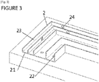
- the first fixing element 2 comprises at least a first part 21 forming a base fixed to the support 4, said base having orifices 22.
- these orifices 22 present in the base allow both better evacuation of water while allowing better grip of the covering 5 to the first fixing element 2 by the passage of a part of said floor directly into the element of fixing by said orifices 22 of the base, and therefore a better grip.
- the base 21 comprises a heightening element 9, for example a washer placed under the base 21 before its attachment, or a thickness (not shown) present directly on the face of the base 21 in contact with the support, in order to raise said base, which advantageously makes it possible to facilitate the flow of water.
- the booster element 9 can for example and in a non-limiting manner have a thickness of 5 mm.
- a series of grooves for example 3 millimeters thick and 3 millimeters deep, is made to facilitate the flow of rainwater to the outside of the coating.
- the dimensions of these grooves vary according to the use case and the cited example is not limiting.
- the raising element can also be made in the form of a concrete flashing with a thickness of approximately 5 to 10 cm, placed under the entire base, on the periphery of the covering.
- this greatly facilitates the flow of water when the support is quite porous, for example in compacted gravel, the water then being able to flow through the coating and the support through the center of the covered zone, and the periphery of the coating resting on the concrete flashing.
- the coating 5 has damping properties and comprises at least one damping layer and an aesthetic layer 52 covering said damping layer, the fastening device 1 being at least embedded in the aesthetic layer 52 and/or the damping layer, and preferably both in the damping layer and in the aesthetic layer 52.
- the damping layer can be composed of shredded tires.
- the aesthetic layer 52 can also be damping.
- the aesthetic layer 52 can be composed of ground rubber, for example natural rubber.
- shredded tires have a particle size between 4 and 8mm. Independently, the ground rubber exhibits, for example, a particle size of between 1 and 4 mm.
- the dimensions of the diaper components generally have a grain size between 1mm to 8mm.
- the fixing device 1 is taken in the mass of the two layers.
- the components of the coating 5, for example rubber and/or tire aggregates, can pass through the meshes of the net and/or the expanded metal.
- the shredded materials are trapped in the meshes of the second fixing element 3, and it is then very difficult to dislodge the periphery, or border, of the coating 5 because it is caught, and hooked, in the fixing element.
- the first fastening element 2 has a second part 23 of which at least a portion forms a projection.
- the first fixing element 2 has a second part 23 extending away from the support 4, for example a wall having a non-zero angle with the support 4, preferably vertically with respect to the support 4. This allows the fixing device 1 to be better caught in the mass of the coating 5.
- this part has at least one aerial portion, facing the first part 21 of the first element, forming a base in contact with stand 4.
- the first fastening element 2 does not include a second part 23. It may only include a base 21 from which extends a second element 3, preferably forming a mesh.
- the portion forming a projection forms a right angle with the base of the first fixing element 2, in order to allow better gripping and a better distribution of the forces undergone during the use of the coating 5, by example by trampling.
- the protrusion-forming portion can form various structures suitable for better caking.
- the device is anchored to the support at the level of anchor points 7 present on the base 21.
- these anchor points are made on a part of the base 21 close to the periphery of the coating, rather than on a part more close to the center of the coating.
- the extending portion forms at least one angle.
- the extending portion forms a structure having straight walls formed by right angles.
- the right angles have sharp edges, but it is possible that they have chamfers.
- the presence of sharp edges can improve the grip in the mass of the device with the coating 5, by the distribution of the tensile forces, and by the increase in the contact and bonding surface.
- the first fixing element 2 further comprises orifices 24 in the second part 23 of the first fixing element 2, for example a wall having a non-zero angle with the support 4, for example a vertical wall.
- These orifices 24 can for example have a round, oval or oblong shape.
- the ground material can pass through the orifices 22, 24 of the base and of the wall of the first fixing element 2, the ground material then being trapped during their drying.
- this makes it possible to improve the effectiveness of caking with the coating 5 and therefore the fixing of the coating 5, without hindering the evacuation of water, the shredded material forming the different layers of the coating 5 being permeable to water. 'water.
- the second fixing element 3 which will be embedded in the mass in the coating 5 can be between approximately 7 and 15 cm depending on the thickness and the surface area of the coating 5 to be produced.
- the orifices 22 present on the base can for example be spaced apart by 10 cm.
- the first fastening element 2 forms at least one angle iron. This allows the floor to have an additional grip point formed by the vertical wall of the angle iron.
- the angle iron has a height of 3 cm, a width of 6 cm.
- first fixing elements each forming an angle iron it is possible to produce coverings 5 having the shapes of squares, rectangles, hexagonal and octagons.
- angles are nestable to make bends, for example 15°, 30°, 45°, 90°, incoming and/or outgoing angles.
- the first fixing element 2, for example forming an angle iron and the second fixing element 3, for example forming a mesh can be made in one piece.
- the mesh can be deployed at from the end of the base to then join the inclined wall, and continue beyond, towards the center of the coating 5.
- the two fixing elements are coupled by fixing means, for example screws or nails.
- the first fixing element 2 comprises a base forming a mesh in contact with the support 4.
- it can also comprise a second part 23 forming a mesh, and forming an inclined wall, the two parts being embedded in the coating 5.
- the first and second part are made of the same material, preferably in the same part.
- the first part 21 forming the base has a dimension between approximately 2 to 5 cm, preferably approximately 3 to 4 cm, this dimension being able to vary according to the thickness of the covering 5 to be fixed. This may include grooves 8 or thicknesses to respectively improve water evacuation or rigidity.
- the second part 23 forming the net has a length of between approximately 7 cm and 18 cm, the length being able to vary according to the thickness of the covering 5 to be fixed.
- the notches thus made in the mesh allow the borders to follow any profile, shape or angle.
- the notches can for example be spaced 15cm from each other on the base in contact with the support 4 and being adapted according to the configuration of the desired shapes.
- this type of fixing device 1 allows the realization of all possible shapes by bending and rounding of the net, including at the level of the angle between the base and the portion forming a projection, in other words the part Aerial.
- a multitude of possibilities at the level of the angle between the base and the aerial part is possible depending on the final thickness desired for the coating 5 as illustrated, by way of example, in figure 8 .
- the first fastening element 2 is formed of several angles. These angles each have a second part 23 of which at least one portion forms a projection, that is to say aerial parts, which can have the same height, or on the contrary have different dimensions.
- the fixing device 1 comprises only the first fixing element 2, without thread, and is formed of 5 vertical walls connected by a base in 4 parts.
- the number of vertical walls may vary depending on the embodiments. Increasing the number of vertical walls makes it possible to increase the number of attachment points and thus improve the fixing and the durability of the covering 5 on the support 4 and on the fixing device 1.
- the angles close to the center of the covering 5 each have a portion forming a higher projection than that of the angles further from the center, and therefore closer to the periphery or edge of the covering 5.
- the vertical walls close to the edge of coating 5 have lower heights than the vertical walls close to the center of coating 5.
- the height of the walls is defined by the height of the coating 5, and must not exceed half the height of said coating 5.
- they preferably measure a maximum of 1 cm in height in order to facilitate access to the playground and not represent an obstacle.
- the highest wall cannot exceed half the height of the final coating.
- the bends formed between two angles can have angles between 15° and 90° in order to adapt to different configurations of desired shapes.
- the angles have an "L" shape, in order to form vertical walls offering an optimal contact surface with the coating 5.
- orifices 22 are present over the entire first part 21 forming the base in order to guarantee the evacuation of water. These orifices 22 are preferably between 4 and 8 mm, preferably 6 mm.
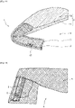
- the aggregates of the shredded material stick to the walls of the compartments as illustrated in figure 4 .
- the bonding surface is therefore larger.
- the presence of the largest wall, being the wall closest to the center of the coating 5, therefore prevents the detachment of the aggregates during trampling, the pressure being exerted mainly from the top downwards.
- the fixing device 1 comprises a first fixing element 2, without thread, but with a first and a second part 23.
- the fixing element has the shape of an elongated "H", in other words a structure having straight walls, formed by right angles, and which has orifices 22, 24 allowing better evacuation of water and better maintenance of the layers of the coating 5.
- the fixing device 1 is made of extruded recycled plastic.
- this makes it possible to reduce the environmental impact, thanks to a very versatile material for the production of shapes because it is very flexible and solid at the same time.
- this material presents less risk of cuts in the event of exposure of the fastening device 1, and cannot rust, unlike certain metals.
- the material being flexible it is possible to make all shapes, however it is also possible to provide inward and/or outward angles of 15° to 90° to make the binding more versatile.
- the second part 23 of the first fixing element 2 forming a projection may comprise a vertical part and a horizontal part, the two parts possibly having orifices 24 allowing better evacuation of water and better maintenance of the adhesion of the layers of the coating 5 Grooves 8, for example in the direction of the width, can be made during manufacture under the base, first part 21 of the first element fixed to the support 4, in order to further promote the evacuation of water.
- the dimensions of the first fixing element 2 have a height of approximately 20mm, a width of the high horizontal wall of approximately 25mm, a width at the level of the base of approximately 35 to 45mm .
- the first fixing element 2 can also have holes 22 of approximately 10mm, approximately every 5 cm and holes 24 on the vertical wall of approximately 10mm ⁇ 30mm, approximately every 5 cm in order to ensure a better grip in the mass.
- the fastening system comprises a first fastening element 2 formed for example of plastic which can be recycled, molded and/or extruded, and a second fastening element 3 forming a mesh, for example a fiberglass net.
- the first element 2, for example made of recycled plastic comprises a first part 21 composed of a wall forming a base in contact and fixed with the support 4 and does not comprise a second part 23.
- the second fixing element 3 can be present on the whole of the base 21 or only on a part, as represented in the figure 6 .
- the wall of the first fixing element 2 has a rounded outer edge.
- this facilitates access to the playground by presenting a height at the periphery of the coating 5 that is zero or almost zero in order to reduce the risk of tripping for a young user.
- the wall has a thickness of about 5 mm which includes orifices 24, preferably 10, 20 or 30 mm in order to increase the hooking and bonding surface.
- orifices 24 promote the evacuation of rainwater and at the same time increase the gripping surface of the covering 5 in order to ensure optimum bonding.
- This type of invisible edging fastener is ideal for small thicknesses of flooring 5, and it is easy to cut it to the desired degree to achieve any desired shape.
- the fiberglass mesh has meshes whose size is between 6mm and 25mm.
- the fiberglass net can be molded to the first fixing element 2, and has a length of between about 12 and 15 cm depending on the thickness of the coating 5.
- the meshes of the fiberglass mesh as well as the perforations of the part in contact with the ground trap the aggregates and form a single part, making the detachment of the aggregates very difficult or almost impossible in normal use.
- the mesh is placed halfway between the top of the covering 5 and the support 4 in order to ensure optimum maintenance of the edges of the covering 5, which has the additional advantage for the mesh of not be in contact with the support 4.
- the mesh is thus protected against damage due to frost, even when there is stagnant water present at the level of the support surface 4.
- the figure 7 represents a coating device 5 comprising a first and a second fastening element 3, once said coating 5 has been deposited on the fastening device 1 and fixed to the support 4 by the latter.
- the two layers of the coating 5 both take the two fixing elements in the mass.
- the fixing device 1 is fixed by anchoring the base of the first fixing element 2 directly to the support 4 by anchoring means chosen from bolting, chemical or conventional anchors, for example at part of the orifices 22 of said base.
- the spitage is used in the case of a concrete support 4, while the fixing by chemical anchor is used in the case of a coated support 4.
- the deposition of the glue layer is generally carried out by using a glue roller.
- the deposition of glue at least at the edges and therefore at the level of the first fixing element 2, is carried out by a pressure gun, such as a glue gun, for more precision, and for a more even spread over the entire surface to be bonded.
- the fixing of the first fixing element 2 to the support 4 carried out by a bolt or by a chemical anchor according to the support 4, can be raised by 2 to 3 mm to promote the flow and the evacuation of the water, so that freezing standing water does not damage the system.
- the device makes it possible to fix a coating on a bare support, but can also be used in situations of restoration of a coating in poor condition, peeled off for example.
- a coating is present before the installation of a device, for example in the case of a restoration of a detached coating, it is possible to cut and/or remove only the edges of the coating, in order to to access the support at its edges.
- the device is then fixed and then covered with the coating in order to be solidified therein.
- the coating can thus be deposited and glued only at the level of the edges to be replaced, leaving the center of the coating intact, still in good condition. This has the advantage of reducing the amount of materials used for a restoration, concentrating on the restoration and fixing of the more fragile edges.
- the edges are then fixed firmly and durably, thanks to the device.
- the installer For installation, the installer provides the thickness of the coating 5 according to the potential fall height of the installed equipment.
- the glue is deposited by a pressure gun at least on the fixing device 1.
- the coating 5 comprises at least one damping layer (51) and an aesthetic layer 52 covering the damping layer, and where, following the mixing of its components of each layer with glue, the damping layer is deposited on at least the support 4, and preferably on at least a part of the fixing device 1, then the aesthetic layer 52 is deposited on at least the damping layer and preferably on at least a part of the fixing device 1.
- the deposition is carried out so that the fixing device 1 is taken in the mass of the two layers.
- the user's potential fall height differs depending on the more or less high coating thickness 5 chosen.
- an aluminum expanded metal about 1 centimeter in height for example. After pouring the coating aggregates and drying, the coating is held together by the expanded metal. In this configuration, it is no longer necessary to use a bonding primer or a layer of polyurethane adhesive, usually applied before casting the aggregates, which is an environmental advantage.
- the present invention also relates to a method for repairing a covering device 5 of a support 4 by means of a fixing device 1 comprising at least a first fixing element 2.
- This repair method is for example implemented when an existing coating device 5 suffers damage and peels off on its periphery. However, this method can also be implemented when carrying out the fixing of a new coating 5 on a support 4.
- the method comprises a step of exposing the support 4 on the parts of the coating device 5 that need to be repaired. For a detachment at the edge of the coating, it is thus necessary to cut the part of the coating which is peeling off in order to remove it and have access to the underlying support 4.
- the method comprises the production of a first fastening element 2 along the length of the covering device 5 to be repaired, by producing a longitudinal slot 10 .
- This can, for example, be made in the support 4 or in an added edge 11 fixed to the support 4.
- the slot 10 can be made in a support 4 when the latter is for example made of concrete, asphalt, asphalt, wood or any other material in which a slot 10 can be produced.
- a slot 10 can be made in an added curb 11, when the latter is for example made of concrete curbs of type P1 or P2, asphalt, asphalt, wood or any other hard material in which a slot 10 can be made.
- Coated and asphalt are, for example, materials chosen so that the border 11 has a specific geometric shape at the location where this border 11 is positioned.
- this is a section made of recycled plastic, aluminum or any other material suitable for making a profile.
- the use of a profile makes it possible, for example, to make the slot 10 during the manufacture of said profile rather than making it a posteriori with a router.
- the slot 10 is for example placed on its upper part 12 or on its side part 13.
- the slot 10 is made for example with a trapezoidal shape of the "dovetail” type, the shape of an inverted “T", a "U” slightly closed or straight on its upper part, or else all another form requiring the production of a slot 10 with a narrowed upper part and a lower part of increased size.
- the slot 10 has for example a depth of a few centimeters, for example 2 centimeters and has for example a width of a size ranging from a few millimeters to a few centimeters.
- the depth of the slot 10 requires a depth of the material in which the slot 10 is present at least greater than the depth of the slot 10, for example 4 centimeters if the slot 10 is 2 centimeters deep.
- the slots can be made in all shapes, all depths and all possible widths depending on the configuration, the height of the floors or the nature of the supports.
- the method according to the first embodiment also comprises a step of inserting a second fixing element 3 into the slot 10.
- a mesh 3 which extends from the slot 10 towards the center coating 5. It has for example a width of more than twenty centimeters.
- This is, for example, a fiberglass net, a polypropylene mesh, an aluminum expanded metal or a perforated sheet.
- the mesh 3 makes it possible to maintain the coating 5 once in place thanks to its honeycomb shape.
- a fixing mixture 14 contains, for example, epoxy adhesive, or a chemical sealant or any other sealing material, or even, depending on its dimensions, rubber mixed with polyurethane glue and fiberglass flakes.
- the coating 5 is cast on the support 4 to be coated as well as above and below the mesh 3 and the slot 10. It comprises a damping lower layer 51 and an aesthetic upper layer 52 composed for example of Diene Monomer, polyurethane glue and fiberglass flakes.
- the mesh 3 is taken in the coating 5, for example between the two layers or in one of the two layers.
- a layer of glue 15 mixed with fiberglass flakes is applied to the old coating 16 in order to solidify the joint between the old 16 and the new coating 5, visible figure 10 .
- the fixing device 1 obtained between the mesh 3 and the aggregates present in the slot 10 is taken in the mass of the covering 5 and makes it possible to fix the covering 5 to the support 4.
- the slot is replaced by a succession of holes, the bottom of the hole of which is wider than the top in order to be able to insert pieces of mesh and the coating therein so that, after drying, the coating is fixed to the support by this device taken in its mass.
- the holes are drilled in the support or in an added border and have a frustoconical shape.
- the mesh pieces have for example a size of about 10 centimeters long, depending on the thickness of the coating, and a few centimeters wide.
- the coating is for example a mixture of aggregates and fiberglass flakes.
- the first fixing element 2 is directly fixed to the support 4. It is for example a set of chemical plugs, plastic or brass, nails, screws or other fixing elements. These first fixing elements 2 are placed over the entire length of the covering device 5 to be repaired and are spaced apart, for example, by about fifteen centimeters.
- the method according to the second mode of implementation also comprises a step of inserting a second fixing element 3 fixed between the support 4 and the first fixing element 2.
- a mesh 3 which extends from the first fastening element 2 towards the center of the coating 5. It has for example a width of more than twenty centimeters.
- These are, for example, a fiberglass net, a polypropylene mesh, an aluminum expanded metal or perforated sheet.
- the mesh 3 makes it possible to maintain the coating 5 once in place thanks to its honeycomb shape.
- the coating 5 is then cast on the support 4 to be coated as well as over the mesh 3 and the first fixing element 2. It comprises a damping lower layer 51 and an aesthetic upper layer 52 composed for example of Ethylene-Propylene- Diene Monomer, polyurethane glue and fiberglass flakes.
- the color of the new aesthetic layer 52 is for example different from the original color of the old coating 16 in order to indicate that the latter has been repaired.
- Mesh 3 is taken from covering 5, by example between the two layers or in one of the two layers. Beforehand, a layer of polyurethane glue 15 mixed with fiberglass flakes is applied to the old covering 16 in order to durably solidify the joint between the old 16 and the new covering 5.
- the fixing device 1 obtained between the mesh 3 and the first fixing element 2 is taken in the mass of the covering 5 and makes it possible to fix the covering 5 to the support 4.
- the first fixing element 2 is an aluminum tube with a square or round section and a diameter of between 5 and 15 millimeters depending on the final thickness of the coating 5.
- Aluminum is easily moldable and makes it possible to create any shape of covering periphery 5. It is fixed to the support 4 using fixing lugs 17 arranged at variable distances, for example nailed or screwed to the support.
- a fiberglass mesh 3 is fixed between the aluminum tube 2 and the support 4, which makes it possible to cover this fixing device 1 with the coating 5 with a thin coating.
- the mesh is in particular taken in the mass of the coating on its upper side and on its lower side, the coating being fixed vis-à-vis the latter since passing through the meshes of the mesh.
- the first fixing element 2 is for example a rail or a thin aluminum border fixed to the support.
- a mesh is fixed between the rail and the support and extends inwards.
- a step of covering this fixing device is then carried out with the pouring of the covering.
- the first fixing element 2 is for example a rail or a thin plastic border fixed to the support.
- a mesh is fixed between the rail and the support and extends inwards.
- a step of covering this fixing device is then carried out with the pouring of the covering.
Landscapes
- Engineering & Computer Science (AREA)
- Architecture (AREA)
- Civil Engineering (AREA)
- Structural Engineering (AREA)
- Road Paving Structures (AREA)
- Coating Apparatus (AREA)
- Floor Finish (AREA)
Claims (15)
- Vorrichtung zur Verkleidung (5) einer Halterung (4), wobei die Vorrichtung Folgendes umfasst:- eine Verkleidung (5), vorzugsweise stoßdämpfend, konfiguriert, um die Halterung (4) zu bedecken,- eine Vorrichtung zur Befestigung (1) der Verkleidung (5) auf der Halterung (4),wobei die Befestigungsvorrichtung (1) wenigstens ein erstes Befestigungselement (2) umfasst, konfiguriert, um direkt auf einer Oberfläche der Halterung (4) befestigt zu werden durch Verankerungsmittel konfiguriert gemäß der Beschaffenheit der Halterung (4),dadurch gekennzeichnet, dass die Befestigungsvorrichtung (1) vollständig in die Masse der Verkleidung (5) einbezogen ist.
- Vorrichtung zur Verkleidung (5) einer Halterung (4) nach Anspruch 1, wobei das erste Befestigungselement (2) einen Rand bildet, der wenigstens einen Teil der zu bedeckenden Oberfläche (4) begrenzt.
- Vorrichtung zur Verkleidung (5) einer Halterung (4) nach Anspruch 1, wobei das erste Befestigungselement (2) ausschließlich auf der Oberfläche der Halterung (4) befestigt ist.
- Vorrichtung zur Verkleidung (5) einer Bodenhalterung (4) nach Anspruch 1, wobei die Befestigungsvorrichtung (1) weiter wenigstens ein zweites Befestigungselement (3) umfasst, das an das erste Befestigungselement (2) gekoppelt ist und das sich zum Inneren, vorzugsweise dem Zentrum, der Verkleidung (5) erstreckt.
- Vorrichtung zur Verkleidung (5) einer Halterung (4) nach einem der vorhergehenden Ansprüche, wobei das zweite Befestigungselement (3) ein Maschennetz bildet.
- Vorrichtung zur Verkleidung (5) einer Halterung (4) nach einem der vorhergehenden Ansprüche, wobei das erste Befestigungselement (2) wenigstens einen ersten Teil (21) umfasst, der eine an der Halterung (4) befestigte Basis bildet, wobei die Basis Öffnungen (22) aufweist.
- Vorrichtung zur Verkleidung (5) einer Halterung (4) nach einem der vorhergehenden Ansprüche, wobei das erste Befestigungselement (2) wenigstens einen zweiten Teil (23) aufweist, von dem wenigstens ein Abschnitt einen Vorsprung bildet.
- Vorrichtung zur Verkleidung (5) einer Halterung (4) nach einem der vorhergehenden Ansprüche, wobei die Befestigungsvorrichtung (1) durch Verankerung der Basis des ersten Befestigungselements (2) direkt auf der Halterung (4) befestigt ist, vorzugsweise durch Verankerungsmittel ausgewählt gemäß der Halterung (4), auf der die Vorrichtung befestigt ist.
- Vorrichtung zur Verkleidung (5) einer Halterung (4) nach einem der vorhergehenden Ansprüche, wobei die Verkleidung (5) stoßdämpfende Eigenschaften besitzt und wenigstens eine stoßdämpfende Schicht und eine ästhetische Schicht (52) umfasst, die die stoßdämpfende Schicht überdeckt, wobei die Befestigungsvorrichtung (1) wenigstens in die Masse der ästhetischen Schicht (52) und/oder der stoßdämpfenden Schicht einbezogen ist, und vorzugsweise sowohl in die stoßdämpfende Schicht als auch in die ästhetische Schicht (52).
- Vorrichtung zur Verkleidung (5) einer Halterung (4) nach einem der vorhergehenden Ansprüche, wobei die Befestigungsvorrichtung (1) weiter Öffnungen (24) in dem zweiten Teil (23) des ersten Befestigungselements (2) umfasst.
- Verfahren zur Reparatur einer Vorrichtung zur Verkleidung (5) einer Halterung (4) nach Anspruch 1, dadurch gekennzeichnet, dass es die folgenden Schritte umfasst:- Freilegen der Halterung (4) auf dem zu reparierenden Teil;- Anbringen und Befestigen der Befestigungsvorrichtung (1) wenigstens am Rand des zu bedeckenden Teils der Halterung (4);- Aufbringen von Klebstoff (15) auf dem Teil der alten Verkleidung (16), der dafür bestimmt ist, in Kontakt mit der neuen Verkleidung (5) zu sein;- Mischen der Komponenten der Verkleidung (5) mit Klebstoff, dann Aufbringen auf die Befestigungsvorrichtung (1) und auf den zu bedeckenden Teil der Halterung (4), solcherart, dass die Verkleidung (5) die Befestigungsvorrichtung (1) vollständig bedeckt, sodass die Befestigungsvorrichtung (1) in die Masse der Verkleidung (5) einbezogen ist; und- Trocknen der Verkleidung (5).
- Verfahren nach Anspruch 11, wobei das erste Befestigungselement (2) ein Schlitz (10) ist, eingearbeitet in die Halterung (4) oder eingearbeitet in einen angesetzten Rand (11), der auf der Halterung (4) befestigt ist.
- Verfahren nach Anspruch 11, wobei das erste Befestigungselement (2) ausschließlich auf der Oberfläche der Halterung (4) befestigt ist.
- Verfahren nach einer der Ansprüche 11 bis 13, wobei die Befestigungsvorrichtung (1) weiter wenigstens ein zweites Befestigungselement (3) umfasst, das mit dem ersten Befestigungselement (2) gekoppelt ist und sich zum Inneren, vorzugsweise dem Zentrum, der Verkleidung (5) erstreckt.
- Verfahren nach Anspruch 14, wobei das erste Befestigungselement (3) ein Maschennetz bildet.
Applications Claiming Priority (1)
| Application Number | Priority Date | Filing Date | Title |
|---|---|---|---|
| FR1904588A FR3095660B1 (fr) | 2019-04-30 | 2019-04-30 | DISPOSITIF de revêtement de surface |
Publications (2)
| Publication Number | Publication Date |
|---|---|
| EP3770324A1 EP3770324A1 (de) | 2021-01-27 |
| EP3770324B1 true EP3770324B1 (de) | 2022-04-20 |
Family
ID=67262753
Family Applications (1)
| Application Number | Title | Priority Date | Filing Date |
|---|---|---|---|
| EP20172321.0A Active EP3770324B1 (de) | 2019-04-30 | 2020-04-30 | Oberflächenbeschichtungseinrichtung und verfahren zur deren reparatur |
Country Status (2)
| Country | Link |
|---|---|
| EP (1) | EP3770324B1 (de) |
| FR (1) | FR3095660B1 (de) |
Family Cites Families (2)
| Publication number | Priority date | Publication date | Assignee | Title |
|---|---|---|---|---|
| US20080248887A1 (en) * | 2007-04-03 | 2008-10-09 | The Shane Group | Method of crating a fall-safe, synthetic turf-covered play area |
| JP4931949B2 (ja) * | 2008-03-18 | 2012-05-16 | 明和工業株式会社 | 路面仮復旧用部材及び路面仮復旧工法 |
-
2019
- 2019-04-30 FR FR1904588A patent/FR3095660B1/fr active Active
-
2020
- 2020-04-30 EP EP20172321.0A patent/EP3770324B1/de active Active
Also Published As
| Publication number | Publication date |
|---|---|
| FR3095660B1 (fr) | 2021-06-04 |
| EP3770324A1 (de) | 2021-01-27 |
| FR3095660A1 (fr) | 2020-11-06 |
Similar Documents
| Publication | Publication Date | Title |
|---|---|---|
| EP3206868B1 (de) | Folie zum schutz der oberfläche einer schalung, schalungsinstallation, verfahren zur herstellung und verfahren zur verwendung | |
| EP3770324B1 (de) | Oberflächenbeschichtungseinrichtung und verfahren zur deren reparatur | |
| EP2453078B1 (de) | Vorrichtung zur Oberflächenabschöpfung eines Schwimmbades und mit einer solchen Vorrichtung ausgestattetes Schwimmbad | |
| FR2970981A3 (fr) | Element de revetement de sol pour zones de circulation | |
| WO2018007731A1 (fr) | Dalle composite et systeme de revetement comprenant de telles dalles | |
| WO2006075111A1 (fr) | Dispositif de depose reguliere de mortier sur des blocs de maconnerie | |
| FR3082544A1 (fr) | Dispositif pour un plot de terrasse, plot comprenant un tel dispositif et installation de terrasse sur plots comprenant des elements de planchers supportes par de tels plots | |
| EP0360682B1 (de) | Dehnungsfuge für Betonbodenbelag | |
| FR2976603A1 (fr) | Toiture vegetalisee | |
| EP1231337B1 (de) | Feuchtraum und sein Montageverfahren | |
| FR3106601A1 (fr) | Dalle de revêtement de surface de voirie | |
| FR2693751A1 (fr) | Plaque de revêtement de sol praticable pour couches de drainage et de protection et revêtement de sol correspondant. | |
| LU101676B1 (fr) | Elément de couverture d'une surface | |
| LU101145B1 (fr) | Procédé et kit pour le placement d'éléments de façade | |
| FR3105274A3 (fr) | Procédé de formation d'une couche de construction dotée d'un passage | |
| FR2972013A1 (fr) | Procede de realisation d'un revetement d'etancheite a l'eau sous un revetement de sol, profile permettant la mise en oeuvre d'un tel procede et revetement d'etancheite obtenu par une telle mise en oeuvre | |
| WO2000061872A1 (fr) | Procede de realisation d'un joint de chaussee souple, et joint obtenu par un tel procede | |
| CA3137814A1 (fr) | Element de coffrage et procede de construction d'une structure en beton dans une cavite | |
| FR3026752A1 (fr) | Dalle amortissante pour sol d'aires de jeux | |
| FR3094388A1 (fr) | Bassin d'agrement constitue de panneaux en pierre | |
| FR2656885A1 (fr) | Revetement ameliore pour la protection des sols sujets a l'erosion, et procede de mise en óoeuvre. | |
| FR2896000A1 (fr) | Dallage non structurel et son procede de realisation | |
| FR3051489A1 (fr) | Procede de pose ajustee d'une couverture d'un regard d'ouvrage en chaussee et dispositif de couverture adapte | |
| FR2934625A1 (fr) | Revetement de sol carrele flottant. | |
| EP2218848A1 (de) | Block für eine verlorene Schalung und Modul für den Bau einer solchen Schalung |
Legal Events
| Date | Code | Title | Description |
|---|---|---|---|
| PUAI | Public reference made under article 153(3) epc to a published international application that has entered the european phase |
Free format text: ORIGINAL CODE: 0009012 |
|
| STAA | Information on the status of an ep patent application or granted ep patent |
Free format text: STATUS: THE APPLICATION HAS BEEN PUBLISHED |
|
| AK | Designated contracting states |
Kind code of ref document: A1 Designated state(s): AL AT BE BG CH CY CZ DE DK EE ES FI FR GB GR HR HU IE IS IT LI LT LU LV MC MK MT NL NO PL PT RO RS SE SI SK SM TR |
|
| AX | Request for extension of the european patent |
Extension state: BA ME |
|
| STAA | Information on the status of an ep patent application or granted ep patent |
Free format text: STATUS: REQUEST FOR EXAMINATION WAS MADE |
|
| 17P | Request for examination filed |
Effective date: 20210628 |
|
| GRAP | Despatch of communication of intention to grant a patent |
Free format text: ORIGINAL CODE: EPIDOSNIGR1 |
|
| STAA | Information on the status of an ep patent application or granted ep patent |
Free format text: STATUS: GRANT OF PATENT IS INTENDED |
|
| INTG | Intention to grant announced |
Effective date: 20211130 |
|
| GRAS | Grant fee paid |
Free format text: ORIGINAL CODE: EPIDOSNIGR3 |
|
| GRAA | (expected) grant |
Free format text: ORIGINAL CODE: 0009210 |
|
| STAA | Information on the status of an ep patent application or granted ep patent |
Free format text: STATUS: THE PATENT HAS BEEN GRANTED |
|
| RBV | Designated contracting states (corrected) |
Designated state(s): AL AT BE BG CH CY CZ DE DK EE ES FI GB GR HR HU IE IS IT LI LT LU LV MC MK MT NL NO PL PT RO RS SE SI SK SM TR |
|
| AK | Designated contracting states |
Kind code of ref document: B1 Designated state(s): AL AT BE BG CH CY CZ DE DK EE ES FI GB GR HR HU IE IS IT LI LT LU LV MC MK MT NL NO PL PT RO RS SE SI SK SM TR |
|
| REG | Reference to a national code |
Ref country code: GB Ref legal event code: FG4D Free format text: NOT ENGLISH |
|
| REG | Reference to a national code |
Ref country code: CH Ref legal event code: EP |
|
| REG | Reference to a national code |
Ref country code: IE Ref legal event code: FG4D Free format text: LANGUAGE OF EP DOCUMENT: FRENCH |
|
| REG | Reference to a national code |
Ref country code: DE Ref legal event code: R096 Ref document number: 602020002718 Country of ref document: DE |
|
| REG | Reference to a national code |
Ref country code: AT Ref legal event code: REF Ref document number: 1485222 Country of ref document: AT Kind code of ref document: T Effective date: 20220515 |
|
| REG | Reference to a national code |
Ref country code: LT Ref legal event code: MG9D |
|
| REG | Reference to a national code |
Ref country code: NL Ref legal event code: MP Effective date: 20220420 |
|
| REG | Reference to a national code |
Ref country code: AT Ref legal event code: MK05 Ref document number: 1485222 Country of ref document: AT Kind code of ref document: T Effective date: 20220420 |
|
| PG25 | Lapsed in a contracting state [announced via postgrant information from national office to epo] |
Ref country code: NL Free format text: LAPSE BECAUSE OF FAILURE TO SUBMIT A TRANSLATION OF THE DESCRIPTION OR TO PAY THE FEE WITHIN THE PRESCRIBED TIME-LIMIT Effective date: 20220420 |
|
| PG25 | Lapsed in a contracting state [announced via postgrant information from national office to epo] |
Ref country code: SE Free format text: LAPSE BECAUSE OF FAILURE TO SUBMIT A TRANSLATION OF THE DESCRIPTION OR TO PAY THE FEE WITHIN THE PRESCRIBED TIME-LIMIT Effective date: 20220420 Ref country code: PT Free format text: LAPSE BECAUSE OF FAILURE TO SUBMIT A TRANSLATION OF THE DESCRIPTION OR TO PAY THE FEE WITHIN THE PRESCRIBED TIME-LIMIT Effective date: 20220822 Ref country code: NO Free format text: LAPSE BECAUSE OF FAILURE TO SUBMIT A TRANSLATION OF THE DESCRIPTION OR TO PAY THE FEE WITHIN THE PRESCRIBED TIME-LIMIT Effective date: 20220720 Ref country code: LT Free format text: LAPSE BECAUSE OF FAILURE TO SUBMIT A TRANSLATION OF THE DESCRIPTION OR TO PAY THE FEE WITHIN THE PRESCRIBED TIME-LIMIT Effective date: 20220420 Ref country code: HR Free format text: LAPSE BECAUSE OF FAILURE TO SUBMIT A TRANSLATION OF THE DESCRIPTION OR TO PAY THE FEE WITHIN THE PRESCRIBED TIME-LIMIT Effective date: 20220420 Ref country code: GR Free format text: LAPSE BECAUSE OF FAILURE TO SUBMIT A TRANSLATION OF THE DESCRIPTION OR TO PAY THE FEE WITHIN THE PRESCRIBED TIME-LIMIT Effective date: 20220721 Ref country code: FI Free format text: LAPSE BECAUSE OF FAILURE TO SUBMIT A TRANSLATION OF THE DESCRIPTION OR TO PAY THE FEE WITHIN THE PRESCRIBED TIME-LIMIT Effective date: 20220420 Ref country code: ES Free format text: LAPSE BECAUSE OF FAILURE TO SUBMIT A TRANSLATION OF THE DESCRIPTION OR TO PAY THE FEE WITHIN THE PRESCRIBED TIME-LIMIT Effective date: 20220420 Ref country code: BG Free format text: LAPSE BECAUSE OF FAILURE TO SUBMIT A TRANSLATION OF THE DESCRIPTION OR TO PAY THE FEE WITHIN THE PRESCRIBED TIME-LIMIT Effective date: 20220720 Ref country code: AT Free format text: LAPSE BECAUSE OF FAILURE TO SUBMIT A TRANSLATION OF THE DESCRIPTION OR TO PAY THE FEE WITHIN THE PRESCRIBED TIME-LIMIT Effective date: 20220420 |
|
| PG25 | Lapsed in a contracting state [announced via postgrant information from national office to epo] |
Ref country code: RS Free format text: LAPSE BECAUSE OF FAILURE TO SUBMIT A TRANSLATION OF THE DESCRIPTION OR TO PAY THE FEE WITHIN THE PRESCRIBED TIME-LIMIT Effective date: 20220420 Ref country code: PL Free format text: LAPSE BECAUSE OF FAILURE TO SUBMIT A TRANSLATION OF THE DESCRIPTION OR TO PAY THE FEE WITHIN THE PRESCRIBED TIME-LIMIT Effective date: 20220420 Ref country code: LV Free format text: LAPSE BECAUSE OF FAILURE TO SUBMIT A TRANSLATION OF THE DESCRIPTION OR TO PAY THE FEE WITHIN THE PRESCRIBED TIME-LIMIT Effective date: 20220420 Ref country code: IS Free format text: LAPSE BECAUSE OF FAILURE TO SUBMIT A TRANSLATION OF THE DESCRIPTION OR TO PAY THE FEE WITHIN THE PRESCRIBED TIME-LIMIT Effective date: 20220820 |
|
| REG | Reference to a national code |
Ref country code: DE Ref legal event code: R097 Ref document number: 602020002718 Country of ref document: DE |
|
| PG25 | Lapsed in a contracting state [announced via postgrant information from national office to epo] |
Ref country code: SM Free format text: LAPSE BECAUSE OF FAILURE TO SUBMIT A TRANSLATION OF THE DESCRIPTION OR TO PAY THE FEE WITHIN THE PRESCRIBED TIME-LIMIT Effective date: 20220420 Ref country code: SK Free format text: LAPSE BECAUSE OF FAILURE TO SUBMIT A TRANSLATION OF THE DESCRIPTION OR TO PAY THE FEE WITHIN THE PRESCRIBED TIME-LIMIT Effective date: 20220420 Ref country code: RO Free format text: LAPSE BECAUSE OF FAILURE TO SUBMIT A TRANSLATION OF THE DESCRIPTION OR TO PAY THE FEE WITHIN THE PRESCRIBED TIME-LIMIT Effective date: 20220420 Ref country code: MC Free format text: LAPSE BECAUSE OF FAILURE TO SUBMIT A TRANSLATION OF THE DESCRIPTION OR TO PAY THE FEE WITHIN THE PRESCRIBED TIME-LIMIT Effective date: 20220420 Ref country code: EE Free format text: LAPSE BECAUSE OF FAILURE TO SUBMIT A TRANSLATION OF THE DESCRIPTION OR TO PAY THE FEE WITHIN THE PRESCRIBED TIME-LIMIT Effective date: 20220420 Ref country code: DK Free format text: LAPSE BECAUSE OF FAILURE TO SUBMIT A TRANSLATION OF THE DESCRIPTION OR TO PAY THE FEE WITHIN THE PRESCRIBED TIME-LIMIT Effective date: 20220420 Ref country code: CZ Free format text: LAPSE BECAUSE OF FAILURE TO SUBMIT A TRANSLATION OF THE DESCRIPTION OR TO PAY THE FEE WITHIN THE PRESCRIBED TIME-LIMIT Effective date: 20220420 |
|
| PLBE | No opposition filed within time limit |
Free format text: ORIGINAL CODE: 0009261 |
|
| STAA | Information on the status of an ep patent application or granted ep patent |
Free format text: STATUS: NO OPPOSITION FILED WITHIN TIME LIMIT |
|
| 26N | No opposition filed |
Effective date: 20230123 |
|
| PG25 | Lapsed in a contracting state [announced via postgrant information from national office to epo] |
Ref country code: AL Free format text: LAPSE BECAUSE OF FAILURE TO SUBMIT A TRANSLATION OF THE DESCRIPTION OR TO PAY THE FEE WITHIN THE PRESCRIBED TIME-LIMIT Effective date: 20220420 |
|
| PG25 | Lapsed in a contracting state [announced via postgrant information from national office to epo] |
Ref country code: IE Free format text: LAPSE BECAUSE OF NON-PAYMENT OF DUE FEES Effective date: 20220430 |
|
| PG25 | Lapsed in a contracting state [announced via postgrant information from national office to epo] |
Ref country code: SI Free format text: LAPSE BECAUSE OF FAILURE TO SUBMIT A TRANSLATION OF THE DESCRIPTION OR TO PAY THE FEE WITHIN THE PRESCRIBED TIME-LIMIT Effective date: 20220420 |
|
| PGFP | Annual fee paid to national office [announced via postgrant information from national office to epo] |
Ref country code: DE Payment date: 20230427 Year of fee payment: 4 Ref country code: CH Payment date: 20230502 Year of fee payment: 4 |
|
| PGFP | Annual fee paid to national office [announced via postgrant information from national office to epo] |
Ref country code: BE Payment date: 20230427 Year of fee payment: 4 |
|
| PG25 | Lapsed in a contracting state [announced via postgrant information from national office to epo] |
Ref country code: IT Free format text: LAPSE BECAUSE OF FAILURE TO SUBMIT A TRANSLATION OF THE DESCRIPTION OR TO PAY THE FEE WITHIN THE PRESCRIBED TIME-LIMIT Effective date: 20220420 |
|
| REG | Reference to a national code |
Ref country code: DE Ref legal event code: R081 Ref document number: 602020002718 Country of ref document: DE Owner name: ISEO INNOVATION, FR Free format text: FORMER OWNER: CUNSOLO, FILIPPO, SAINTRY-SUR-SEINE, FR |
|
| REG | Reference to a national code |
Ref country code: BE Ref legal event code: PD Owner name: ISEO INNOVATION; FR Free format text: DETAILS ASSIGNMENT: CHANGE OF OWNER(S), ASSIGNMENT; FORMER OWNER NAME: CUNSOLO, FILIPPO Effective date: 20240201 |
|
| REG | Reference to a national code |
Ref country code: LU Ref legal event code: PD Owner name: ISEO INNOVATION (SOCIETE PAR ACTIONS SIMPLIFIEE); FR Free format text: FORMER OWNER: CUNSOLO, FILIPPO Effective date: 20240208 |
|
| PG25 | Lapsed in a contracting state [announced via postgrant information from national office to epo] |
Ref country code: MK Free format text: LAPSE BECAUSE OF FAILURE TO SUBMIT A TRANSLATION OF THE DESCRIPTION OR TO PAY THE FEE WITHIN THE PRESCRIBED TIME-LIMIT Effective date: 20220420 Ref country code: CY Free format text: LAPSE BECAUSE OF FAILURE TO SUBMIT A TRANSLATION OF THE DESCRIPTION OR TO PAY THE FEE WITHIN THE PRESCRIBED TIME-LIMIT Effective date: 20220420 |
|
| PGFP | Annual fee paid to national office [announced via postgrant information from national office to epo] |
Ref country code: LU Payment date: 20240429 Year of fee payment: 5 |