EP3770047A1 - Structure de carrosserie de véhicule et véhicule - Google Patents
Structure de carrosserie de véhicule et véhicule Download PDFInfo
- Publication number
- EP3770047A1 EP3770047A1 EP20185910.5A EP20185910A EP3770047A1 EP 3770047 A1 EP3770047 A1 EP 3770047A1 EP 20185910 A EP20185910 A EP 20185910A EP 3770047 A1 EP3770047 A1 EP 3770047A1
- Authority
- EP
- European Patent Office
- Prior art keywords
- vehicle
- door
- reinforcement
- pillar
- panel
- Prior art date
- Legal status (The legal status is an assumption and is not a legal conclusion. Google has not performed a legal analysis and makes no representation as to the accuracy of the status listed.)
- Granted
Links
- 230000002787 reinforcement Effects 0.000 claims abstract description 143
- 230000002093 peripheral effect Effects 0.000 claims abstract description 12
- 239000005357 flat glass Substances 0.000 claims description 3
- 238000010521 absorption reaction Methods 0.000 description 13
- 238000006243 chemical reaction Methods 0.000 description 8
- 239000013585 weight reducing agent Substances 0.000 description 7
- 230000005540 biological transmission Effects 0.000 description 5
- 239000000446 fuel Substances 0.000 description 2
- 229910000831 Steel Inorganic materials 0.000 description 1
- 239000000463 material Substances 0.000 description 1
- 230000004048 modification Effects 0.000 description 1
- 238000012986 modification Methods 0.000 description 1
- 238000005192 partition Methods 0.000 description 1
- 239000010959 steel Substances 0.000 description 1
Images


Classifications
-
- B—PERFORMING OPERATIONS; TRANSPORTING
- B60—VEHICLES IN GENERAL
- B60J—WINDOWS, WINDSCREENS, NON-FIXED ROOFS, DOORS, OR SIMILAR DEVICES FOR VEHICLES; REMOVABLE EXTERNAL PROTECTIVE COVERINGS SPECIALLY ADAPTED FOR VEHICLES
- B60J5/00—Doors
- B60J5/04—Doors arranged at the vehicle sides
- B60J5/042—Reinforcement elements
- B60J5/0455—Reinforcement elements integrated in door structure or other door elements, e.g. beam-like shapes stamped in inner door panel
-
- B—PERFORMING OPERATIONS; TRANSPORTING
- B62—LAND VEHICLES FOR TRAVELLING OTHERWISE THAN ON RAILS
- B62D—MOTOR VEHICLES; TRAILERS
- B62D25/00—Superstructure or monocoque structure sub-units; Parts or details thereof not otherwise provided for
- B62D25/02—Side panels
-
- B—PERFORMING OPERATIONS; TRANSPORTING
- B60—VEHICLES IN GENERAL
- B60J—WINDOWS, WINDSCREENS, NON-FIXED ROOFS, DOORS, OR SIMILAR DEVICES FOR VEHICLES; REMOVABLE EXTERNAL PROTECTIVE COVERINGS SPECIALLY ADAPTED FOR VEHICLES
- B60J5/00—Doors
- B60J5/04—Doors arranged at the vehicle sides
- B60J5/042—Reinforcement elements
- B60J5/0422—Elongated type elements, e.g. beams, cables, belts or wires
- B60J5/0438—Elongated type elements, e.g. beams, cables, belts or wires characterised by the type of elongated elements
- B60J5/0443—Beams
-
- B—PERFORMING OPERATIONS; TRANSPORTING
- B60—VEHICLES IN GENERAL
- B60J—WINDOWS, WINDSCREENS, NON-FIXED ROOFS, DOORS, OR SIMILAR DEVICES FOR VEHICLES; REMOVABLE EXTERNAL PROTECTIVE COVERINGS SPECIALLY ADAPTED FOR VEHICLES
- B60J5/00—Doors
- B60J5/04—Doors arranged at the vehicle sides
- B60J5/042—Reinforcement elements
- B60J5/0422—Elongated type elements, e.g. beams, cables, belts or wires
- B60J5/0423—Elongated type elements, e.g. beams, cables, belts or wires characterised by position in the lower door structure
- B60J5/0427—Elongated type elements, e.g. beams, cables, belts or wires characterised by position in the lower door structure the elements being arranged along the lower edge of door
-
- B—PERFORMING OPERATIONS; TRANSPORTING
- B60—VEHICLES IN GENERAL
- B60J—WINDOWS, WINDSCREENS, NON-FIXED ROOFS, DOORS, OR SIMILAR DEVICES FOR VEHICLES; REMOVABLE EXTERNAL PROTECTIVE COVERINGS SPECIALLY ADAPTED FOR VEHICLES
- B60J5/00—Doors
- B60J5/04—Doors arranged at the vehicle sides
- B60J5/042—Reinforcement elements
- B60J5/0422—Elongated type elements, e.g. beams, cables, belts or wires
- B60J5/0423—Elongated type elements, e.g. beams, cables, belts or wires characterised by position in the lower door structure
- B60J5/0429—Elongated type elements, e.g. beams, cables, belts or wires characterised by position in the lower door structure the elements being arranged diagonally
-
- B—PERFORMING OPERATIONS; TRANSPORTING
- B60—VEHICLES IN GENERAL
- B60J—WINDOWS, WINDSCREENS, NON-FIXED ROOFS, DOORS, OR SIMILAR DEVICES FOR VEHICLES; REMOVABLE EXTERNAL PROTECTIVE COVERINGS SPECIALLY ADAPTED FOR VEHICLES
- B60J5/00—Doors
- B60J5/04—Doors arranged at the vehicle sides
- B60J5/042—Reinforcement elements
- B60J5/045—Panel type elements
-
- B—PERFORMING OPERATIONS; TRANSPORTING
- B60—VEHICLES IN GENERAL
- B60J—WINDOWS, WINDSCREENS, NON-FIXED ROOFS, DOORS, OR SIMILAR DEVICES FOR VEHICLES; REMOVABLE EXTERNAL PROTECTIVE COVERINGS SPECIALLY ADAPTED FOR VEHICLES
- B60J5/00—Doors
- B60J5/04—Doors arranged at the vehicle sides
- B60J5/042—Reinforcement elements
- B60J5/0456—Behaviour during impact
- B60J5/0458—Passive coupling of the reinforcement elements to the door or to the vehicle body
-
- B—PERFORMING OPERATIONS; TRANSPORTING
- B62—LAND VEHICLES FOR TRAVELLING OTHERWISE THAN ON RAILS
- B62D—MOTOR VEHICLES; TRAILERS
- B62D21/00—Understructures, i.e. chassis frame on which a vehicle body may be mounted
- B62D21/15—Understructures, i.e. chassis frame on which a vehicle body may be mounted having impact absorbing means, e.g. a frame designed to permanently or temporarily change shape or dimension upon impact with another body
- B62D21/157—Understructures, i.e. chassis frame on which a vehicle body may be mounted having impact absorbing means, e.g. a frame designed to permanently or temporarily change shape or dimension upon impact with another body for side impacts
-
- B—PERFORMING OPERATIONS; TRANSPORTING
- B62—LAND VEHICLES FOR TRAVELLING OTHERWISE THAN ON RAILS
- B62D—MOTOR VEHICLES; TRAILERS
- B62D25/00—Superstructure or monocoque structure sub-units; Parts or details thereof not otherwise provided for
- B62D25/02—Side panels
- B62D25/025—Side sills thereof
-
- B—PERFORMING OPERATIONS; TRANSPORTING
- B62—LAND VEHICLES FOR TRAVELLING OTHERWISE THAN ON RAILS
- B62D—MOTOR VEHICLES; TRAILERS
- B62D25/00—Superstructure or monocoque structure sub-units; Parts or details thereof not otherwise provided for
- B62D25/04—Door pillars ; windshield pillars
-
- B—PERFORMING OPERATIONS; TRANSPORTING
- B62—LAND VEHICLES FOR TRAVELLING OTHERWISE THAN ON RAILS
- B62D—MOTOR VEHICLES; TRAILERS
- B62D25/00—Superstructure or monocoque structure sub-units; Parts or details thereof not otherwise provided for
- B62D25/08—Front or rear portions
- B62D25/14—Dashboards as superstructure sub-units
- B62D25/145—Dashboards as superstructure sub-units having a crossbeam incorporated therein
-
- B—PERFORMING OPERATIONS; TRANSPORTING
- B62—LAND VEHICLES FOR TRAVELLING OTHERWISE THAN ON RAILS
- B62D—MOTOR VEHICLES; TRAILERS
- B62D25/00—Superstructure or monocoque structure sub-units; Parts or details thereof not otherwise provided for
- B62D25/20—Floors or bottom sub-units
- B62D25/2009—Floors or bottom sub-units in connection with other superstructure subunits
- B62D25/2036—Floors or bottom sub-units in connection with other superstructure subunits the subunits being side panels, sills or pillars
Definitions
- the present invention relates to a vehicle-body structure of a vehicle, and a vehicle.
- the above-described patent document discloses a door for a vehicle which is provided with panel portions which are arranged on a cabin inward side and on a cabin outward side, a frame portion which is arranged between the panel portions, and a reinforcement portion which is arranged at the frame portion, wherein the frame portion comprises front and rear parts which respectively extend in a vertical direction at front-side and rear-side portions of the panel portions and a lower part which interconnects respective lower portions of the front and rear parts, and the reinforcement portion comprises a first reinforcement which interconnects the above-described front and rear parts and a second reinforcement which interconnects the first reinforcement and the above-described lower part.
- a vehicle-body structure of the vehicle is required to suppress a center pillar from coming into a cabin as much as possible in the vehicle side collision.
- weight reduction of the vehicle (light-weight vehicle) is also required from viewpoints of the fuel economy and the like. Therefore, it is necessary to compatibly attain the further weight reduction of the vehicle and increasing of the amount of absorption of the collision load (the collision-load absorption performance) in the vehicle side collision.
- the weight is so increased that it may be difficult to satisfy the above-described requirements.
- the present invention has been devised in view of the above-described matter, and an object of the present invention is to compatibly attain the weight reduction of the vehicle and increasing of the amount of absorption of the collision load in the vehicle side collision.
- the present invention is a vehicle-body structure of a vehicle, comprising a vehicle-body frame member forming an opening portion for entrance at a vehicle side part, and a side door provided so as to open and/or close the opening portion, wherein the side door comprises a door panel portion and a reinforcement portion provided at a peripheral part of the door panel portion such that the reinforcement portion overlaps with the vehicle-body frame member in a vehicle side view.
- the reinforcement portion is a plate member.
- the side door in the vehicle side collision, the side door is moved (pushed) toward the cabin and comes to contact the vehicle-body frame member.
- the door panel portion receives a reaction load from the vehicle-body frame member in addition to the collision load.
- the reinforcement portion is positioned so as to overlap with the vehicle-body frame member in the vehicle side view (i.e., when viewed from the vehicle width direction)
- the door panel portion since the reinforcement portion is positioned so as to overlap with the vehicle-body frame member in the vehicle side view (i.e., when viewed from the vehicle width direction), even if the door panel portion receives the collision load and the reaction load from the vehicle-body frame member, deformation of the peripheral part of the door panel portion is suppressed. Thereby, the door panel portion remains contacting with the vehicle-body frame member without coming into the cabin. Consequently, the collision load of the vehicle side collision is transmitted from the side door to the vehicle-body frame member, being dispersed to a whole part of the door panel portion.
- the reinforcement portion is the plate member, the weight increase of the side door can be suppressed as much as possible.
- the weight reduction of the vehicle and increasing of the amount of absorption of the collision load in the vehicle side collision can be compatibly attained.
- the vehicle-body frame member comprises a side sill, a hinge pillar, a center pillar, and a roof side rail.
- the peripheral part of the door panel portion comprises plural overlapping portions which respectively overlap with the side sill, the hinge pillar, the center pillar.
- the roof side rail in the vehicle side view, and the reinforcement portion comprises a lower-side reinforcement portion attached to the overlapping portion which overlaps with the side sill, a front-side reinforcement portion attached to the overlapping portion which overlaps with the hinge pillar, a rear-side reinforcement portion attached to the overlapping portion which overlaps with the center pillar, and an upper-side reinforcement portion attached to the overlapping portion which overlaps with the roof side rail.
- the reinforcement portions are respectively provided at a front side, a rear side, an upper side, and a lower side of the side door, the deformation of the side door can be effectively suppressed in the vehicle side collision.
- the collision load can be transmitted from a whole part of the side door to the vehicle-body frame member. Consequently, the amount of absorption of the collision load in the vehicle side collision can be more increased.
- the vehicle-body frame member comprises a floor cross member provided at a position which overlaps with the side sill in the vehicle side view and extending in a vehicle width direction, and the lower-side reinforcement portion is configured to overlap with the floor cross member in the vehicle side view.
- the floor cross member extends in the vehicle width direction, a portion of the side sill which overlaps with the floor cross member has high rigidity against the collision load applied from the vehicle side. Accordingly, since the lower-side reinforcement is configured to overlap with the floor cross member in the vehicle side view (i.e., when viewed from the vehicle width direction), the collision load of the vehicle side collision can be effectively transmitted to the vehicle-body frame member. Thereby, the amount of absorption of the collision load in the vehicle side collision can be further increased.
- the vehicle-body frame member comprises an instrument-panel member provided at a position which overlaps with the hinge pillar in the vehicle side view and extending in the vehicle width direction, and the front-side reinforcement portion is configured to overlap with the instrument-panel member in the vehicle side view.
- the instrument-panel member extends in the vehicle width direction, a portion of the hinge pillar which overlaps with the instrument-panel member has high rigidity against the collision load applied from the vehicle side. Accordingly, since the front-side reinforcement portion is configured to overlap with the instrument-panel member in the vehicle side view (i.e., when viewed from the vehicle width direction), the collision load of the vehicle side collision can be effectively transmitted to the vehicle-body frame member. Thereby, the amount of absorption of the collision load in the vehicle side collision can be more further increased.
- the front-side reinforcement portion and/or the rear-side reinforcement portion is configured to overlap with an impact bar.
- the upper-side reinforcement portion is located at the same position, in the longitudinal direction, as a roof cross member.
- the side door is a front side door.
- the side door is a rear side door.
- the reinforcement portions is configured to overlap with at least a wheel arch in the vehicle side view.
- the door panel portion has a door inner panel and a door outer panel.
- the door inner panel includes at least any one of an inner front portion extending along the hinge pillar, an inner rear portion extending along the center pillar, an inner lower portion extending along the side sill, and a window frame portion configured to form an opening portion to be closed with a window glass.
- the inner front portion is the overlapping portion configured to overlap with the hinge pillar.
- the inner rear portion is the overlapping portion configured to overlap with the center pillar.
- the inner lower portion is the overlapping portion configured to overlap with the side sill.
- the window frame portion is the overlapping portion configured to overlap with the roof side rail.
- a vehicle includes the above vehicle-body structure.
- front, rear, left, right, upper and lower which respectively mean directions relative to a vehicle 1 will be simply referred to as "front,” “rear,” “left,” “right,” “upper,” and “lower.”
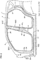
- FIG. 1 shows a left-side side part of the vehicle 1 to which a vehicle-body structure according to the present embodiment is applied.
- the vehicle 1 is particularly a 4-door type of passenger car.
- the vehicle-body structure of the vehicle 1 since the vehicle-body structure of the vehicle 1 is configured to be laterally symmetrical, the vehicle-body structure of the left-side part of the vehicle 1 will be described specifically only, and detailed explanation of the one of a right-side part of the vehicle 1 will be omitted. Further, in the following description, there is a case where an inward side, in a vehicle width direction, of the vehicle 1 will be simply referred to as "right side” and also an outward side, in the vehicle width direction, of the vehicle 1 will be simply referred to as "left side.”
- the vehicle 1 comprises a vehicle-body frame member 2 which forms front-side and rear-side opening portions for entrance 3, 4 at its left-side side part, through which a passenger gets on or gets off.
- a front side door 5 is arranged at the front-side opening portion 3 so as to open and close this opening portion 3.
- a rear side door 6 is arranged at the rear-side opening portion 4 so as to open and close this opening portion 4.
- the vehicle-body frame member 2 particularly comprises, as shown in FIG. 2 , a side sill 10 which is arranged at a lower part of the vehicle 1 and extends in a longitudinal direction, a hinge pillar 20 which extends upwardly from a front-side end portion of the side sill 10, a front pillar 30 which extends obliquely rearwardly-and-upwardly from an upper-side end portion of the hinge pillar 20, and a roof side rail 31 which continuously extends rearwardly from a rear-side end portion of the front pillar 30.
- the vehicle-body frame member 2 further comprises a center pillar 40 which extends in a vertical direction and interconnects a central part, in the longitudinal direction, of the side sill 10 and a central part, in the longitudinal direction, of the roof side rail 31.
- the front-side opening portion 3 is partitioned by the side sill 10, the hinge pillar 20, the front pillar 30, the roof side rail 31, and the center pillar 40.
- the vehicle-body frame member 2 particularly comprises a wheel arch 50 which extends upwardly-and-rearwardly in an arch shape from a rear-side end portion of the side sill 10 and forms a part of a wheel house and a quarter pillar 51 which extends vertically and interconnects the wheel arch 50 and the roof side rail 31.
- the rear-side opening portion 4 is partitioned by the side sill 10, the roof side rail 31, the center pillar 40, the wheel arch 50, and the quarter pillar 51.
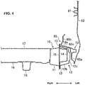
- the side sill 10 particularly comprises, as shown in FIG. 4 , a side-sill inner panel 11 which is positioned on the inward side, in the vehicle width direction, of the vehicle 1 (on the right side in this figure) and has a hat-shaped cross section and a side-sill outer panel 12 which is positioned on the outward side, in the vehicle width direction, of the vehicle 1 (on the left side in this figure) and has a hat-shaped cross section.
- the cross section of the side-sill inner panel 11 is opened to the left side
- the cross section of the side-sill outer panel 12 is opened to the right side.
- Each of the side-sill inner panel 11 and the side-sill outer panel 12 has side-sill flanges 13 which extend in the vertical direction and in the longitudinal direction at its upper-side end portion and its lower-side end portion.
- the respective side-sill flanges 13 overlap with each other in the vehicle width direction and are welded together.
- a closed-cross section is formed by the side-sill inner panel 11 and the side-sill outer panel 12.
- the side-sill outer panel 12 particularly comprises, as shown in FIG. 4 , a side-sill upper wall portion 12a which extends toward the left side from a lower-side end portion of the upper-side side-sill flange 13, a side-sill lower wall portion 12b which extends, facing the side-sill upper wall portion 12a in the vertical direction, and a side-sill side wall portion 12c which interconnects a left-side end portion of the side-sill upper wall portion 12a and a left-side end portion of the side-sill lower wall portion 12b in the vertical direction.
- a first side-sill reinforcement 14 and a second side-sill reinforcement 15 are particularly provided inside the side sill 10.
- the first side-sill reinforcement 14 is configured to have a hat-shaped cross section which is opened to the right side, and arranged along the side-sill outer panel 12.
- the second side-sill reinforcement 15 is of a flat plate shape. Respective end portion, in the vertical direction, of the first side-sill reinforcement 14 overlap with the respective side-sill flanges 13 in the vehicle width direction and are welded together with the side-sill flanges 13.
- the second side-sill reinforcement 15 is welded to a right side of the first side-sill reinforcement 14.
- a left-side end portion of a floor panel 16 which expands in the longitudinal direction and in the vehicle width direction is joined to a lower-side portion of the side-sill inner panel 11.
- a left-side end portion of a first floor cross member 17 which extends in the vehicle width direction is joined to an upper-side portion of the side-sill inner panel 11.
- a floor side rail 18 which extends in the longitudinal direction is joined to a lower face of the floor panel 16.
- the hinge pillar 20 comprises one or more, particularly two front-door hinges 21 to support the front side door 5.
- the two front-door hinges 21 are provided to be spaced apart from each other in the vertical direction.
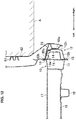
- the hinge pillar 20 particularly comprises, as shown in FIG. 5 , a hinge-pillar inner panel 22 which is positioned on the inward side, in the vehicle width direction, of the vehicle 1 (on the right side in this figure) and has a hat-shaped cross section and a hinge-pillar outer panel 23 which is positioned on the outward side, in the vehicle width direction, of the vehicle 1 (on the left side in this figure) and has a hat-shaped cross section.
- the cross section of the hinge-pillar inner panel 22 is opened to the left side
- the cross section of the hinge-pillar outer panel 23 is opened to the right side.
- Each of the hinge-pillar inner panel 22 and the hinge-pillar outer panel 23 has hinge-pillar flanges 24 which extend in the vertical direction and in the longitudinal direction at its front-side end portion and its rear-side end portion.
- the respective hinge-pillar flanges 24 overlap with each other in the vehicle width direction and are welded together.
- a closed-cross section is formed by the hinge-pillar inner panel 22 and the hinge-pillar outer panel 23.
- the hinge-pillar outer panel 23 particularly comprises, as shown in FIG. 5 , a hinge-pillar front wall portion 23a which extends toward the left side from a rear-side end portion of the upper-side hinge-pillar flange 24, a hinge-pillar rear wall portion 23b which extends, facing the hinge-pillar front wall portion 23a in the longitudinal direction, and a hinge-pillar side wall portion 23c which interconnects a left-side end portion of the hinge-pillar front wall portion 23a and a left-side end portion of the hinge-pillar rear wall portion 23b in the longitudinal direction.
- a hinge-pillar reinforcement 25 is particularly provided inside the hinge pillar 20.
- the hinge-pillar reinforcement 25 is configured to have a hat-shaped cross section which is opened to the right side, and arranged along the hinge-pillar outer panel 23. Respective end portions, in the longitudinal direction, of the hinge-pillar reinforcement 25 overlap with the respective hinge-pillar flanges 24 in the vehicle width direction and are welded together with the hinge-pillar flanges 24.
- the front-side end portion of the hinge-pillar reinforcement 25 does not overlap with the hinge-pillar flange 24.
- its front-side end portion overlaps with the hinge-pillar flanges 24 as well.
- an instrument-panel member 26 is particularly joined to the hinge-pillar inner panel 22.
- the instrument-panel member 26 is provided with hinges 26a to pivotably support a glove box in the vertical direction and others.
- a dash panel 27 which partitions a cabin from an engine room is joined to a front-side end portion of the hinge-pillar inner panel 22.
- the center pillar 40 is provided with one or more, particularly two rear-door hinges 41 to support the openable rear side door 6.
- the two rear-door hinges 41 are provided to be spaced apart from each other in the vertical direction.
- the center pillar 40 is further provided with a striker 42 at its front-side position which is located slightly below the upper-side rear-door hinge 41.
- the striker 42 is a member to lock the front side door 5 in a closed state.
- the center pillar 40 particularly comprises, as shown in FIG. 6 , a center-pillar inner panel 43 which is positioned on the inward side, in the vehicle width direction, of the vehicle 1 (on the right side in this figure) and has a hat-shaped cross section and a center-pillar outer panel 44 which is positioned on the outward side, in the vehicle width direction, of the vehicle 1 (on the left side in this figure) and has a hat-shaped cross section.
- the cross section of the center-pillar inner panel 43 is opened to the left side
- the cross section of the center-pillar outer panel 44 is opened to the right side.
- Each of the center-pillar inner panel 43 and the center-pillar outer panel 44 has center-pillar flanges 45 which extend in the vertical direction and in the longitudinal direction at its front-side end portion and its rear-side end portion.
- the respective center-pillar flanges 45 overlap with each other in the vehicle width direction and are welded together.
- a closed-cross section is formed by the center-pillar inner panel 43 and the center-pillar outer panel 44.
- the center-pillar outer panel 44 particularly comprises, as shown in FIG. 6 , a center-pillar front wall portion 44a which extends toward the left side from a rear-side end portion of the front-side center-pillar flange 45, a center-pillar rear wall portion 44b which extends, facing the center-pillar front wall portion 44a in the longitudinal direction, and a center-pillar side wall portion 44c which interconnects a left-side end portion of the center-pillar front wall portion 44a and a left-side end portion of the center-pillar rear wall portion 44b in the longitudinal direction.
- a center-pillar reinforcement 46 is provided inside the center pillar 40.
- the center-pillar reinforcement 46 is configured to have a hat-shaped cross section which is opened to the right side, and arranged along the center-pillar outer panel 44. Respective end portion, in the longitudinal direction, of the center-pillar reinforcement 46 overlap with the respective center-pillar flanges 45 in the vehicle width direction and are welded together with the center-pillar flanges 45.
- a lower-side end portion of the center pillar 40 is located at the same position as a second floor cross member 47 which extends in the vehicle width direction.
- the roof side rail 31 particularly comprises, as shown in FIG. 7 , a roof-side inner panel 32 which is positioned on the inward side, in the vehicle width direction, of the vehicle 1 (on the right side in this figure) and a roof-side outer panel 33 which is positioned on the outward side, in the vehicle width direction, of the vehicle 1 (on the left side in this figure) and has a C-shaped cross section.
- the cross section of the roof-side outer panel 33 is opened to the right side.
- the roof-side outer panel 33 has a roof-side flange 34 which extends in the vertical direction and in the longitudinal direction at its lower-side end portion.
- the roof-side flange 34 overlaps with a lower-side end portion of the roof-side inner panel 32 in the vehicle width direction and these are welded together.
- An upper-side end portion of the roof-side outer panel 33 overlaps with an upper-side end portion of the roof-side inner panel 32 in the vehicle width direction and these are welded together.
- a closed-cross section is formed by the roof-side inner panel 32 and the roof-side outer panel 33.
- a roof-side reinforcement 35 is particularly provided inside the roof side rail 31.
- the roof-side reinforcement 35 is configured to have a hat-shaped cross section which is opened to the right side, and arranged along the roof-side outer panel 33.
- a lower-side end portion of the roof-side reinforcement 35 overlaps with a lower-side end portion of the roof-side inner panel 32 and the roof-side flange 34 of the roof-side outer panel 33 in the vehicle width direction and these are welded together.
- an upper-side end portion of the roof-side reinforcement 35 overlaps with an upper-side end portion of the roof-side inner panel 32 and an upper-side end portion of the roof-side outer panel 33 in the vehicle width direction and these are welded together.
- a roof cross member 36 which extends in the vehicle width direction is particularly provided on the right side of the roof side rail 31.
- a left-side end portion of the roof cross member 36 is joined to the roof side rail 31.
- the front side door 5 will be described as an example of a side-door structure.
- a state where the front side door 5 closes the front-side opening portion 3 is a premise.
- the rear side door 6 has substantially the same structure as the front side door 5 except a shape of a door panel portion 60 and a shape of a reinforcement portion, which will be described later.
- the front side door 5 comprises, as shown in FIGS. 4 - 8 , the door panel portion 60 which has a door inner panel 61 which is positioned on the inward side, in the vehicle width direction, of the vehicle (on the right side in this figure) and a door outer panel 62 which is positioned on the outward side, in the vehicle width direction, of the vehicle (on the left side in this figure).
- the door inner panel 61 and the door outer panel 62 are welded together so as to have a closed-cross section formed thereby.
- a door trim is joined to a face of the door inner panel 61 which is opposite to the door outer panel 62.
- the door inner panel 61 is particularly made of a single-sheet steel plate.
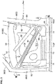
- the door inner panel 61 is formed along a periphery of the front-side opening portion 3 as shown in FIG. 3 .
- the door inner panel 61 particularly comprises at least any one of an inner front portion 63 which extends in the vertical direction along the hinge pillar 20, an inner rear portion 64 which extends in the vertical direction along a lower part of the center pillar 40, and an inner lower portion 65 which extends along the side sill 10 and interconnects a lower-side end portion of the inner front portion 63 and a lower-side end portion of the inner rear portion 64.
- the door inner panel 61 further comprises a beltline portion 66 which extends straightly in the longitudinal direction and interconnects an upper-side end portion of the inner front portion 63 and an upper-side end portion of the inner rear portion 64.
- the door inner panel 61 further comprises a window frame portion 67 which forms a quarter-window opening portion which is closed with a window glass.
- a corner portion between the inner rear portion 64 and the inner lower portion 65 of the door inner panel 61 is configured as a curved portion 68 which is curved smoothly from the inner rear portion 64 toward the inner lower portion 65.
- the inner front portion 63 particularly comprises, as shown in FIG. 5 , a front-side outer wall portion 63a which is positioned at the outside, in a surface direction, of the door inner panel 61 (on the front side in this figure), a front-side inner wall portion 63b which is positioned on the inside, in the surface direction, (on the rear side in this figure) of the front-side outer wall portion 63a, and a front-side connection wall portion 63c which interconnects the front-side outer wall portion 63a and the front-side inner wall portion 63b in the vehicle width direction.
- the front-side outer wall portion 63a comprises a part which expands in the longitudinal direction and in the vertical direction and another part which expands in the vehicle width direction and in the vertical direction continuously from a front-side end portion of the above-described part.
- the front-side inner wall portion 63b expands in the longitudinal direction and in the vertical direction.
- the front-side connection wall portion 63c expands in the vehicle width direction and in the vertical direction so as to interconnect a rear-side end portion of the front-side outer wall portion 63a and a front-side end portion of the front-side inner wall portion 63b.
- the front-side outer wall portion 63a extends in the vertical direction such that this portion 63a overlaps with the rear-side hinge-pillar flange 24 and the hinge-pillar side wall portion 23c of the hinge pillar 20 in the vehicle side view (i.e., when viewed from the vehicle width direction).
- the front-side inner wall portion 63b extends in the vertical direction such that this portion 63b overlaps with the rear-side hinge-pillar flange 24 of the hinge pillar 20 in the vehicle side view (i.e., when viewed from the vehicle width direction).
- the inner front portion 63 forms an overlapping portion which overlaps with the hinge pillar 20.
- the inner rear portion 64 comprises, as shown in FIG. 6 , a rear-side outer wall portion 64a which is positioned at the outside, in a surface direction, of the door inner panel 61 (on the rear side in this figure), a rear-side inner wall portion 64b which is positioned on the inside, in the surface direction, (on the front side in this figure) of the rear-side outer wall portion 64a, and a rear-side connection wall portion 64c which interconnects the rear-side outer wall portion 64a and the rear-side inner wall portion 64b in the vehicle width direction.
- the rear-side outer wall portion 64a comprises a part which expands in the longitudinal direction and in the vertical direction and another part which expands in the vehicle width direction and in the vertical direction continuously from a rear-side end portion of the above-described part.
- the rear-side inner wall portion 64b expands in the longitudinal direction and in the vertical direction.
- the rear-side connection wall portion 64c expands in the vehicle width direction and in the vertical direction so as to interconnect a front-side end portion of the rear-side outer wall portion 64a and a rear-side end portion of the rear-side inner wall portion 64b.
- a ridgeline is formed between the rear-side connection wall portion 64c and the rear-side outer wall portion 64a.
- the rear-side outer wall portion 64a extends in the vertical direction such that this portion 64a overlaps with the front-side center-pillar flange 45 and the center-pillar side wall portion 44c of the center pillar 40 in the vehicle side view (i.e., when viewed from the vehicle width direction).
- the rear-side inner wall portion 64b extends in the vertical direction such that this portion 64b overlaps with the front-side center-pillar flange 45 of the center pillar 40 in the vehicle side view (i.e., when viewed from the vehicle width direction).
- the inner rear portion 64 forms an overlapping portion which overlaps with the center pillar 40
- An opening portion for exposing the striker 42 to a door inside (to a space between the door inner panel 61 and the door outer panel 62 ) is provided at a part of the door-inner rear portion 64 which corresponds to the striker 42.
- a door latch is provided at a position of this opening portion of the inner rear portion 64, which is not illustrated.
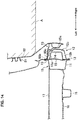
- An engagement state of this door latch with the striker 42 is controlled by operating a door handle 5a (see FIG. 1 ).
- the inner lower portion 65 comprises, as shown in FIG. 4 , a lower-side outer wall portion 65a which is positioned at the outside, in the surface direction, of the door inner panel 61 (on the lower side in this figure), a lower-side inner wall portion 65b which is positioned on the inside, in the surface direction, (on the upper side in this figure) of the lower-side outer wall portion 65a, and a lower-side connection wall portion 65c which interconnects the lower-side outer wall portion 65a and the lower-side inner wall portion 65b in the vehicle width direction.
- the lower-side outer wall portion 65a and the lower-side inner wall portion 65b expand in the longitudinal direction and in the vertical direction.
- the lower-side connection wall portion 65c expands in the vehicle width direction and in the longitudinal direction so as to interconnect an upper-side end portion of the lower-side outer wall portion 65a and a lower-side end portion of the lower-side inner wall portion 65b.
- a ridgeline is formed between the lower-side connection wall portion 65c and the lower-side outer wall portion 65a.
- the lower-side outer wall portion 65a extends in the longitudinal direction such that this portion 65a overlaps with the upper-side side-sill flange 13 and the side-sill side wall portion 12c of the side sill 10 in the vehicle side view (i.e., when viewed from the vehicle width direction).
- the lower-side inner wall portion 65b extends in the longitudinal direction such that this portion 65b overlaps with the upper-side side-sill flange 13 of the side sill 10 in the vehicle side view (i.e., when viewed from the vehicle width direction).
- the inner lower portion 65 forms an overlapping portion which overlaps with the side sill 10.
- the window frame portion 67 comprises, as shown in FIG. 7 , an upper-side outer wall portion 67a which is positioned at the outside, in the surface direction, of the door inner panel 61 (on the upper side in this figure), an upper-side inner wall portion 67b which is positioned on the inside, in the surface direction, (on the lower side in this figure) of the upper-side outer wall portion 67a, and an upper-side connection wall portion 67c which interconnects the upper-side outer wall portion 67a and the upper-side inner wall portion 67b in the vertical direction and in the vehicle width direction.
- the upper-side outer wall portion 67a expands in the longitudinal direction and in the vehicle width direction and slants downwardly toward the right side.
- the upper-side inner wall portion 67b expands in the longitudinal direction and in the vertical direction.
- the lower-side connection wall portion 65c is curved downwardly toward the left side from a right-side end portion of the upper-side outer wall portion 67a so as to interconnect a right-side end portion of the upper-side outer wall portion 67a and an upper-side end portion of the upper-side inner wall portion 67b.
- the upper-side outer wall portion 67a and the upper-side connection portion 67c extend such that they overlap with the roof-side flange 34 in the vehicle sideview (i.e., when viewed from the vehicle width direction).
- the window frame portion 67 forms an overlapping portion which overlaps with the roof side rail 31.
- a first impact bar 81 and a second impact bar 82 are attached to the door inner panel 61.
- the first impact bar 81 extends obliquely rearwardly-and-downwardly and interconnects an upper-side end portion of the inner front portion 63 and a lower-side end portion of the inner rear portion 64.
- the second impact bar 82 extends obliquely rearwardly-and-downwardly so as to interconnect a middle part, in the longitudinal direction, of the beltline portion 66 and a middle part, in the vertical direction, of the inner rear portion 64.
- the first impact bar 81 is configured such that both-side end portions, in the longitudinal direction, thereof have a hat-shaped cross section and a middle portion, in the longitudinal direction, thereof has an M-shaped cross section as shown in FIGS. 4 and 6 .
- the reinforcement portions include a front-side reinforcement portion 71 which is provided along the inner front portion 63, a rear-side reinforcement portion 72 which is provided along the inner rear portion 64, a lower-side reinforcement portion 73 which is provided along the inner lower portion 65, and an upper-side reinforcement portion 74 which is provided at the window frame portion 67.
- the reinforcement portions 71 - 74 may be plate members which are made from hot material, for example.
- the front-side reinforcement portion 71 is a patch member which is attached along the front-side outer wall portion 63a, the front-side inner wall portion 63b, and the front-side connection wall portion 63c as shown in FIG. 3 . That is, the front-side reinforcement portion 71 is provided to extend beyond or straddle a ridgeline between the front-side outer wall portion 63a and the front-side connection wall portion 63c.
- the front-side reinforcement portion 71 is, as shown in FIG. 5 , provided to overlap with the hinge-pillar side wall portion 23c of the hinge pillar 20 in the vehicle side view (i.e., when viewed from the vehicle width direction). Further, the front-side reinforcement portion 71 is provided to overlap with the instrument-panel member 26 in the vehicle side view (i.e., when viewed from the vehicle width direction).
- the front-side reinforcement portion 71 is provided to overlap with an upper-side end portion of the first impact bar 81 in the vehicle side view (i.e., when viewed from the vehicle width direction) as shown in FIGS. 3 and 8 .
- the front-side reinforcement portion 71 is welded to the inner front portion 63 in a state where this portion 71 overlaps with the first impact bar 81 and the inner front portion 63 (specifically, the front-side outer wall portion 63a ) at a joint position of the first impact bar 81 to the door inner panel 61, which is not illustrated.
- the rear-side reinforcement portion 72 is a patch member which is attached along the rear-side outer wall portion 64 and the rear-side connection wall portion 64c as shown in FIG. 3 . That is, the rear-side reinforcement portion 72 is provided to extend beyond or straddle a ridgeline between the rear-side outer wall portion 64a and the rear-side connection wall portion 64c.
- the rear-side reinforcement portion 72 is, as shown in FIG. 5 , provided to overlap with the front-side center-pillar flange 45 and the center-pillar side wall portion 44c of the center pillar 40 in the vehicle side view (i.e., when viewed from the vehicle width direction). Further, the rear-side reinforcement portion 72 is located at the same position, in the longitudinal direction, as the second floor cross member 47.
- the rear-side reinforcement portion 72 is, as shown in FIGS. 3 and 8 , provided to overlap with a lower-side end portion of the first impact bar 81 in the vehicle side view (i.e., when viewed from the vehicle width direction).
- the rear-side reinforcement portion 72 is welded to the inner rear portion 64 in a state where this portion 72 overlaps with the first impact bar 81 and the inner rear portion 64 (specifically, the rear-side outer wall portion 64a ) at a joint position of the first impact bar 81 to the door inner panel 61, which is not illustrated.
- the rear-side reinforcement portion 72 is of a curved shape such that it extends along a curve of the curved portion 68 as shown in FIG. 9 .
- the lower-side reinforcement portion 73 is, as shown in FIG. 4 , configured to have a U-shaped cross section which is opened to the right side and to form a closed-cross section cooperatively with the side sill 10. Specifically, the lower-side reinforcement portion 73 is joined to the lower-side outer wall portion 65a and the lower-side connection wall portion 65c such that this portion 73 extends beyond or straddles the ridgeline between the lower-side outer wall portion 65a and the lower-side connection wall portion 65c and thereby the closed-cross section is formed.
- the lower-side reinforcement portion 73 is provided to overlap with the upper-side side-sill flange 13 and the side-sill side wall portion 12c of the side sill 10 in the vehicle side view (i.e., when viewed from the vehicle width direction). Further, the lower-side reinforcement portion 73 is provided to overlap with the first floor cross member 17 in the vehicle side view (i.e., when viewed from the vehicle width direction).
- the upper-side reinforcement portion 74 is a patch member which is attached along a right-side part of the window frame portion 67 as shown in FIG. 7 .
- the upper-side reinforcement portion 74 is provided to overlap with the roof-side flange 34 of the roof side rail 31 in the vehicle side view (i.e., when viewed from the vehicle width direction). Further, the upper-side reinforcement portion 74 is located at the same position, in the longitudinal direction, as the roof cross member 36.
- the door outer panel 62 determines an outer shape (contour) of the front side door 5, when viewed from an outward side, in the vehicle width direction, of the vehicle 1 as shown in FIG. 1 .
- the rear side door 6 also comprises plural reinforcement portions similarly to the front side door 5. These reinforcement portions are provided at respective portions of a door panel portion of the rear side door 6 which overlap with the center pillar 40, the wheel arch 50, the side sill 10, and the roof side rail 31 in the vehicle side view (i.e., when viewed from the vehicle width direction).
- the vehicle-body structure of the vehicle 1 is required to suppress the center pillar 40 from coming into the cabin as much as possible in the vehicle side view. Further, the weight reduction of the vehicle 1 is recently required from viewpoints of the fuel economy and the like. Therefore, it is necessary to compatibly attain the further weight reduction of the vehicle and increasing of the amount of absorption of the collision load in the vehicle side collision.
- the frame members are arranged between the door inner panel 61 and the door outer panel 62 like a conventional side door, the transmission efficiency of the load may be improved. However, the weight of the vehicle improperly is increased in this case. Therefore, some structure without any frame member arranged may be required.
- FIGS. 10 - 14 show a case where a collision object A collides with the left-side part of the vehicle 1. Further, FIGS. 10 - 14 show the motion of the door panel portion 60 of the front side door 5, omitting illustration of a motion regarding the rear side door 6.
- the inner front portion 63 receives a force directed to the inside, in the surface direction, of the door inner panel 61 (to the rear side in this figure) through this coming-in of the collision object A. Meanwhile, the inner rear portion 64 transmits the collision load to the center pillar 40 and also receives a reaction load from the center pillar 40.
- the inner lower portion 65 comes to contact the upper-side side-sill flange 13 and the side-sill side wall portion 12c of the side sill 10. Accordingly, the inner lower portion 65 transmits the collision load to the side sill 10 and also receives a reaction force from the side sill 10. Further, the inner lower portion 65 receives the force directed to the inside, in the surface direction, of the door inner panel 61 (to the upper side in this figure) through the coming-in of the collision object A.
- the widow frame portion 67 comes to contact the roof side rail 31, which is not illustrated. Accordingly, the widow frame portion 67 transmits the collision load to the roof side rail 31 and also receives a reaction force from the roof side rail 31. Further, the roof side rail 31 receives the force directed to the inside, in the surface direction, of the door inner panel 61 (to the lower side in this figure) through the coming-in of the collision object A.
- the inner front portion 63 is suppressed from being deformed by the front-side reinforcement portion 71.
- the front-side reinforcement portion 71 suppresses the front-side connection wall portion 63c from being bent (bucking deformation) to the inside, in the surface direction, of the door inner panel 61.
- the front-side outer wall portion 63a is suppressed from being deformed to the inside, in the surface direction, of the door inner panel 61. Consequently, the inner front portion 63 maintains its contact state with the hinge pillar 20.
- the inner rear portion 64 is interposed between the collision object A and the center pillar 40 in this collision situation, a contact state of the inner rear portion 64 and the center pillar 40 is maintained.
- the transmission of the collision load from the inner front portion 63 to the hinge pillar 20 can be maintained and also the transmission of the collision load from the inner rear portion 64 to the center pillar 40 can be maintained.
- the collision load of the vehicle side collision is transmitted from the front-side reinforcement portion 71 to the instrument-panel member 26 by way of the hinge pillar 20. Since it extends in the vehicle width direction, the instrument-panel member 26 can receive the collision load properly.
- the rear-side reinforcement portion 72 is located at the same position, in the vehicle longitudinal direction, as the second floor cross member 47 as described above, the collision load of the vehicle side collision is transmitted from the rear-side reinforcement portion 72 to the second floor cross member 47 by way of the center pillar 47 and the side sill 10.
- the second floor cross member 47 can receive the collision load properly.
- the inner lower portion 65 is suppressed from being deformed by the lower-side reinforcement portion 73.
- the lower-side reinforcement portion 73 suppresses the lower-side connection wall portion 65c from being bent (buckling deformation) to the inside, in the surface direction, of the door inner panel 61.
- the lower-side outer wall portion 65a is suppressed from being deformed to the inside, in the surface direction, of the door inner panel 61. Consequently, the inner lower portion 65 maintains its contact state with the side sill 10.
- the transmission of the collision load from the inner lower portion 65 to the side sill 10 can be maintained.
- the collision load of the vehicle side collision is transmitted from the lower-side reinforcement portion 73 to the first floor cross member 17 by way of the side sill 10. Since it extends in the vehicle width direction, the first floor cross member 17 can receive the collision load properly.
- the upper-side connection wall portion 67c of the window frame portion 67 is suppressed from having buckling deformation by the upper-side reinforcement portion 74, which is not illustrated. Thereby, the contact state of the window frame portion 67 and the roof side rail 31 is maintained. Accordingly, the transmission of the collision load from the window frame portion 67 to the rood side rail 31 can be maintained.
- the roof cross member 36 can receive the collision load properly.
- the collision load of the vehicle side collision is transmitted from the front side door 5 to the vehicle-body frame member 2, being dispersed to a whole part of the door panel portion 60, by maintaining the connection state with the peripheral part of the door panel portion 60.
- the amount of absorption of the collision load can be increased.
- the collision load of the vehicle side collision is suppressed from being concentrated at the center pillar 40, the center pillar 40 can be suppressed from coming into the cabin as much as possible.
- the front side door 5 comprises the door panel portion 60 and the reinforcement portions 71 - 74 provided at the peripheral part (the inner front portion 63, the inner rear portion 64, the inner lower portion 65, and the window frame portion 67 ) of the door panel portion 60 such that these reinforcement portions 71 - 74 respectively overlap with the vehicle-body frame member 2 in the vehicle side view (i.e., when viewed from the vehicle width direction), wherein the reinforcement portions 71 - 74 are the plate members.
- the rigidity of the door panel portion 60 against the reaction load applied from the vehicle-body frame member 2 in the vehicle side collision is increased. Accordingly, the deformation of the peripheral part of the door panel portion 60 is suppressed by the reinforcement portions 71 - 74.
- the door panel portion 60 remains contacting with the vehicle-body frame member 2 without coming into the cabin. Therefore, the collision load of the vehicle side collision is transmitted from the front side door 5 to the vehicle-body frame member 2, being dispersed to the whole part of the door panel portion 60. Further, since the reinforcement portions 71 - 74 are the plate members, the weight increase of the front side door 5 can be suppressed as much as possible.
- the weight reduction of the vehicle 1 and increasing of the amount of absorption of the collision load in the vehicle side collision can be compatibly attained.
- the vehicle-body frame member 2 comprises the side sill 10, the hinge pillar 20, the center pillar 40, and the roof side rail 31
- the peripheral part of the door panel portion 60 comprises the plural overlapping portions which respectively overlap with the side sill 10, the hinge pillar 20, the center pillar 40, and the roof side rail 31 in the vehicle side view (i.e., when viewed from the vehicle width direction)
- the reinforcement portions 71 - 74 comprise the lower-side reinforcement portion 73 attached to the lower-side outer wall portion 65a which overlaps with the side sill 10
- the rear-side reinforcement portion 72 attached to the rear-side outer wall portion 64a which overlaps with the center pillar 40
- the upper-side reinforcement portion 74 attached to the upper-side outer wall portion 67a and the upper-side connection wall portion 67c which overlaps with the roof side rail 31.
- the reinforcement portions 71 - 74 are respectively provided at a front side, a rear side, an upper side and a lower side of the front side door 5, the deformation of the front side door 5 can be effectively suppressed in the vehicle side collision. Thereby, the collision load can be transmitted from the whole part of the front side door 5 to the vehicle-body frame member 2. Consequently, the amount of absorption of the collision load in the vehicle side collision can be more increased.
- the vehicle-body frame member 2 comprises the first floor cross member 17 provided at the position which overlaps with the side sill 10 in the vehicle side view (i.e., when viewed from the vehicle width direction) and extending in the vehicle width direction, and the lower-side reinforcement portion 73 is configured to overlap with the first floor cross member 17 in the vehicle side view (i.e., when viewed from the vehicle width direction). That is, a portion of the side sill 10 which overlaps with the first floor cross member 17 has the high rigidity against the collision load applied from the vehicle side.
- the lower-side reinforcement 73 is configured to overlap with the first floor cross member 17 in the vehicle side view (i.e., when viewed from the vehicle width direction), the collision load of the vehicle side collision can be effectively transmitted to the vehicle-body frame member 2. Consequently, the amount of absorption of the collision load in the vehicle side collision can be further increased.
- the vehicle-body frame member 2 comprises the instrument-panel member 26 provided at a position which overlaps with the hinge pillar 20 in the vehicle side view (i.e., when viewed from the vehicle width direction) and extending in the vehicle width direction, and the front-side reinforcement portion 71 is configured to overlap with the instrument-panel member 26 in the vehicle side view (i.e., when viewed from the vehicle width direction). That is, a portion of the hinge pillar 20 which overlaps with the instrument-panel member 26 has the high rigidity against the collision load applied from the vehicle side.
- the front-side reinforcement portion 71 is configured to overlap with the instrument-panel member 26 in the vehicle side view (i.e., when viewed from the vehicle width direction), the collision load of the vehicle side collision can be effectively transmitted to the vehicle-body frame member 2. Consequently, the amount of absorption of the collision load in the vehicle side collision can be further increased.
- the reinforcement portions 71 - 74 are provided at the door inner panel 61 in the above-described embodiment, these portions may be provided at a peripheral portion of the door outer panel 62. In this case, deformation of the door outer panel 62 in the vehicle side collision is so suppressed that it is suppressed that the side door is pushed into the cabin, so that a connection state of the door panel portion 60 and the vehicle-body frame member 2 is maintained.
- an engagement state of the door panel portion 60 and the vehicle-body frame member 2 may be maintained by providing catcher pins as the reinforcement portions 71- 74.
- the door inner panel 61 (the inner lower portion 65 ) forms the closed-cross section together with only the lower-side reinforcement portion 73 in the above-described embodiment
- the front-side reinforcement portion 71, the rear-side reinforcement portion 72, or the upper-side reinforcement portion 74 may form a closed-cross section together with the door inner panel 61.
- the lower-side reinforcement portion 73 may be a patch member attached along the lower-side outer wall portion 65a, the lower-side inner wall portion 65b, and the lower-side connection wall portion 65c, similarly to the front-side reinforcement portion 71 and so on.
- a part or a whole part of the reinforcement portions 71 - 74 may not be configured to be a separate member from the door inner panel 61.
- the reinforcement portions 71 - 74 can be configured by making the plate thickness of a portion of the door inner panel 61 which corresponds to the reinforcement portions 71 - 74 thicker than the other part of the door inner panel 61, for example.
- the reinforcement portions are the front-side reinforcement portion 71, the rear-side reinforcement portion 72, the lower-side reinforcement portion 73, and the upper-side reinforcement portion 74 in the above-described embodiment
- the front-side reinforcement portion 71 and the upper-side reinforcement portion 74 may be omitted as long as the rear-side reinforcement portion 72 and the lower-side reinforcement portion 73 are provided. In this case, it is preferable that the rear-side reinforcement portion 72 and the lower-side reinforcement portion 73 be extended as much as possible.
Landscapes
- Engineering & Computer Science (AREA)
- Mechanical Engineering (AREA)
- Chemical & Material Sciences (AREA)
- Combustion & Propulsion (AREA)
- Transportation (AREA)
- Body Structure For Vehicles (AREA)
Applications Claiming Priority (1)
| Application Number | Priority Date | Filing Date | Title |
|---|---|---|---|
| JP2019135517A JP7487451B2 (ja) | 2019-07-23 | 2019-07-23 | 車両の車体構造 |
Publications (2)
| Publication Number | Publication Date |
|---|---|
| EP3770047A1 true EP3770047A1 (fr) | 2021-01-27 |
| EP3770047B1 EP3770047B1 (fr) | 2023-05-10 |
Family
ID=71620273
Family Applications (1)
| Application Number | Title | Priority Date | Filing Date |
|---|---|---|---|
| EP20185910.5A Active EP3770047B1 (fr) | 2019-07-23 | 2020-07-15 | Structure de carrosserie de véhicule et véhicule |
Country Status (4)
| Country | Link |
|---|---|
| US (1) | US11254195B2 (fr) |
| EP (1) | EP3770047B1 (fr) |
| JP (1) | JP7487451B2 (fr) |
| CN (1) | CN112277589B (fr) |
Families Citing this family (1)
| Publication number | Priority date | Publication date | Assignee | Title |
|---|---|---|---|---|
| EP4132838A4 (fr) * | 2020-04-06 | 2024-05-01 | Shape Corp | Pièce de véhicule à poutre multi-creux |
Citations (10)
| Publication number | Priority date | Publication date | Assignee | Title |
|---|---|---|---|---|
| DE102004029458A1 (de) * | 2004-06-18 | 2006-01-05 | Michael Braun | Bauteil einer Fahrzeugkarosserie und Verfahren zu seiner Herstellung |
| US20080315619A1 (en) * | 2007-06-22 | 2008-12-25 | Toyota Jidosha Kabushiki Kaisha | Vehicle side door structure |
| WO2009051231A1 (fr) * | 2007-10-19 | 2009-04-23 | Toyota Jidosha Kabushiki Kaisha | Structure pour partie latérale de carrosserie de véhicule et véhicule associé |
| DE102012111327A1 (de) * | 2012-08-22 | 2014-02-27 | Hyundai Motor Company | 2- oder 3-türiges Fahrzeug mit einem Verstärkungselement gegen einen Seitenaufprall |
| DE102014115151B3 (de) * | 2014-10-17 | 2016-02-25 | Benteler Automobiltechnik Gmbh | Verfahren zur Herstellung einer Fahrzeugtür |
| EP3025888A1 (fr) * | 2014-11-27 | 2016-06-01 | Toyota Jidosha Kabushiki Kaisha | Structure latérale de véhicule |
| EP3219590A1 (fr) * | 2015-02-25 | 2017-09-20 | Mitsubishi Jidosha Kogyo Kabushiki Kaisha | Structure pour partie latérale de carrosserie de véhicule |
| FR3050705A1 (fr) * | 2016-04-29 | 2017-11-03 | Peugeot Citroen Automobiles Sa | Vehicule avec renforts lateraux en bas de porte |
| WO2018049319A1 (fr) * | 2016-09-09 | 2018-03-15 | Continental Strutural Plastics, Inc. | Composants de portière de véhicule composite formés par des ensembles de moulage par transfert de résine - préimprégnés en feuille |
| JP2018052138A (ja) | 2016-09-26 | 2018-04-05 | 株式会社Subaru | 車両用ドア |
Family Cites Families (9)
| Publication number | Priority date | Publication date | Assignee | Title |
|---|---|---|---|---|
| JP4225028B2 (ja) | 2002-10-11 | 2009-02-18 | マツダ株式会社 | 車両のサイドドアのラッチ取付け構造 |
| JP4277602B2 (ja) * | 2003-07-22 | 2009-06-10 | マツダ株式会社 | 自動車の側部車体構造 |
| JP2008105506A (ja) * | 2006-10-24 | 2008-05-08 | Toyota Motor Corp | 車両用ドア構造 |
| JP2008265693A (ja) * | 2007-04-25 | 2008-11-06 | Mazda Motor Corp | 自動車の側部構造 |
| JP5737167B2 (ja) * | 2011-12-16 | 2015-06-17 | トヨタ自動車株式会社 | 車両用ドア構造 |
| JP5949479B2 (ja) | 2012-11-14 | 2016-07-06 | マツダ株式会社 | ドアミラーの取付構造 |
| JP6179383B2 (ja) | 2013-12-13 | 2017-08-16 | マツダ株式会社 | 車両の側部車体構造 |
| JP2016084031A (ja) * | 2014-10-27 | 2016-05-19 | トヨタ自動車株式会社 | 車両側部構造 |
| JP6149881B2 (ja) * | 2015-02-24 | 2017-06-21 | マツダ株式会社 | 自動車の側部車体構造 |
-
2019
- 2019-07-23 JP JP2019135517A patent/JP7487451B2/ja active Active
-
2020
- 2020-06-23 CN CN202010582885.6A patent/CN112277589B/zh active Active
- 2020-07-14 US US16/929,006 patent/US11254195B2/en active Active
- 2020-07-15 EP EP20185910.5A patent/EP3770047B1/fr active Active
Patent Citations (10)
| Publication number | Priority date | Publication date | Assignee | Title |
|---|---|---|---|---|
| DE102004029458A1 (de) * | 2004-06-18 | 2006-01-05 | Michael Braun | Bauteil einer Fahrzeugkarosserie und Verfahren zu seiner Herstellung |
| US20080315619A1 (en) * | 2007-06-22 | 2008-12-25 | Toyota Jidosha Kabushiki Kaisha | Vehicle side door structure |
| WO2009051231A1 (fr) * | 2007-10-19 | 2009-04-23 | Toyota Jidosha Kabushiki Kaisha | Structure pour partie latérale de carrosserie de véhicule et véhicule associé |
| DE102012111327A1 (de) * | 2012-08-22 | 2014-02-27 | Hyundai Motor Company | 2- oder 3-türiges Fahrzeug mit einem Verstärkungselement gegen einen Seitenaufprall |
| DE102014115151B3 (de) * | 2014-10-17 | 2016-02-25 | Benteler Automobiltechnik Gmbh | Verfahren zur Herstellung einer Fahrzeugtür |
| EP3025888A1 (fr) * | 2014-11-27 | 2016-06-01 | Toyota Jidosha Kabushiki Kaisha | Structure latérale de véhicule |
| EP3219590A1 (fr) * | 2015-02-25 | 2017-09-20 | Mitsubishi Jidosha Kogyo Kabushiki Kaisha | Structure pour partie latérale de carrosserie de véhicule |
| FR3050705A1 (fr) * | 2016-04-29 | 2017-11-03 | Peugeot Citroen Automobiles Sa | Vehicule avec renforts lateraux en bas de porte |
| WO2018049319A1 (fr) * | 2016-09-09 | 2018-03-15 | Continental Strutural Plastics, Inc. | Composants de portière de véhicule composite formés par des ensembles de moulage par transfert de résine - préimprégnés en feuille |
| JP2018052138A (ja) | 2016-09-26 | 2018-04-05 | 株式会社Subaru | 車両用ドア |
Also Published As
| Publication number | Publication date |
|---|---|
| EP3770047B1 (fr) | 2023-05-10 |
| JP2021017200A (ja) | 2021-02-15 |
| US11254195B2 (en) | 2022-02-22 |
| JP7487451B2 (ja) | 2024-05-21 |
| US20210023920A1 (en) | 2021-01-28 |
| CN112277589A (zh) | 2021-01-29 |
| CN112277589B (zh) | 2024-03-08 |
Similar Documents
| Publication | Publication Date | Title |
|---|---|---|
| EP3770048A1 (fr) | Structure de carrosserie de véhicule et véhicule | |
| EP3770044A1 (fr) | Structure de carrosserie de véhicule et véhicule | |
| US11235646B2 (en) | Vehicle-body structure of vehicle | |
| EP3770047A1 (fr) | Structure de carrosserie de véhicule et véhicule | |
| EP3770043A1 (fr) | Structure de carrosserie de véhicule et véhicule | |
| EP3769987A1 (fr) | Structure de carrosserie de véhicule et véhicule | |
| CN112046614B (zh) | 上部车身构造 | |
| JP7379901B2 (ja) | 車両の車体構造 | |
| JP7484101B2 (ja) | 車両の車体構造 | |
| JP2005162089A (ja) | ワンボックス型自動車の車体側部補強構造 |
Legal Events
| Date | Code | Title | Description |
|---|---|---|---|
| PUAI | Public reference made under article 153(3) epc to a published international application that has entered the european phase |
Free format text: ORIGINAL CODE: 0009012 |
|
| STAA | Information on the status of an ep patent application or granted ep patent |
Free format text: STATUS: THE APPLICATION HAS BEEN PUBLISHED |
|
| AK | Designated contracting states |
Kind code of ref document: A1 Designated state(s): AL AT BE BG CH CY CZ DE DK EE ES FI FR GB GR HR HU IE IS IT LI LT LU LV MC MK MT NL NO PL PT RO RS SE SI SK SM TR |
|
| AX | Request for extension of the european patent |
Extension state: BA ME |
|
| STAA | Information on the status of an ep patent application or granted ep patent |
Free format text: STATUS: REQUEST FOR EXAMINATION WAS MADE |
|
| 17P | Request for examination filed |
Effective date: 20210708 |
|
| RBV | Designated contracting states (corrected) |
Designated state(s): AL AT BE BG CH CY CZ DE DK EE ES FI FR GB GR HR HU IE IS IT LI LT LU LV MC MK MT NL NO PL PT RO RS SE SI SK SM TR |
|
| GRAP | Despatch of communication of intention to grant a patent |
Free format text: ORIGINAL CODE: EPIDOSNIGR1 |
|
| STAA | Information on the status of an ep patent application or granted ep patent |
Free format text: STATUS: GRANT OF PATENT IS INTENDED |
|
| INTG | Intention to grant announced |
Effective date: 20230224 |
|
| GRAS | Grant fee paid |
Free format text: ORIGINAL CODE: EPIDOSNIGR3 |
|
| GRAA | (expected) grant |
Free format text: ORIGINAL CODE: 0009210 |
|
| STAA | Information on the status of an ep patent application or granted ep patent |
Free format text: STATUS: THE PATENT HAS BEEN GRANTED |
|
| AK | Designated contracting states |
Kind code of ref document: B1 Designated state(s): AL AT BE BG CH CY CZ DE DK EE ES FI FR GB GR HR HU IE IS IT LI LT LU LV MC MK MT NL NO PL PT RO RS SE SI SK SM TR |
|
| REG | Reference to a national code |
Ref country code: GB Ref legal event code: FG4D |
|
| REG | Reference to a national code |
Ref country code: AT Ref legal event code: REF Ref document number: 1566441 Country of ref document: AT Kind code of ref document: T Effective date: 20230515 Ref country code: CH Ref legal event code: EP |
|
| REG | Reference to a national code |
Ref country code: DE Ref legal event code: R096 Ref document number: 602020010636 Country of ref document: DE |
|
| REG | Reference to a national code |
Ref country code: IE Ref legal event code: FG4D |
|
| REG | Reference to a national code |
Ref country code: LT Ref legal event code: MG9D |
|
| REG | Reference to a national code |
Ref country code: NL Ref legal event code: MP Effective date: 20230510 |
|
| REG | Reference to a national code |
Ref country code: AT Ref legal event code: MK05 Ref document number: 1566441 Country of ref document: AT Kind code of ref document: T Effective date: 20230510 |
|
| PG25 | Lapsed in a contracting state [announced via postgrant information from national office to epo] |
Ref country code: SE Free format text: LAPSE BECAUSE OF FAILURE TO SUBMIT A TRANSLATION OF THE DESCRIPTION OR TO PAY THE FEE WITHIN THE PRESCRIBED TIME-LIMIT Effective date: 20230510 Ref country code: PT Free format text: LAPSE BECAUSE OF FAILURE TO SUBMIT A TRANSLATION OF THE DESCRIPTION OR TO PAY THE FEE WITHIN THE PRESCRIBED TIME-LIMIT Effective date: 20230911 Ref country code: NO Free format text: LAPSE BECAUSE OF FAILURE TO SUBMIT A TRANSLATION OF THE DESCRIPTION OR TO PAY THE FEE WITHIN THE PRESCRIBED TIME-LIMIT Effective date: 20230810 Ref country code: NL Free format text: LAPSE BECAUSE OF FAILURE TO SUBMIT A TRANSLATION OF THE DESCRIPTION OR TO PAY THE FEE WITHIN THE PRESCRIBED TIME-LIMIT Effective date: 20230510 Ref country code: ES Free format text: LAPSE BECAUSE OF FAILURE TO SUBMIT A TRANSLATION OF THE DESCRIPTION OR TO PAY THE FEE WITHIN THE PRESCRIBED TIME-LIMIT Effective date: 20230510 Ref country code: AT Free format text: LAPSE BECAUSE OF FAILURE TO SUBMIT A TRANSLATION OF THE DESCRIPTION OR TO PAY THE FEE WITHIN THE PRESCRIBED TIME-LIMIT Effective date: 20230510 |
|
| PG25 | Lapsed in a contracting state [announced via postgrant information from national office to epo] |
Ref country code: RS Free format text: LAPSE BECAUSE OF FAILURE TO SUBMIT A TRANSLATION OF THE DESCRIPTION OR TO PAY THE FEE WITHIN THE PRESCRIBED TIME-LIMIT Effective date: 20230510 Ref country code: PL Free format text: LAPSE BECAUSE OF FAILURE TO SUBMIT A TRANSLATION OF THE DESCRIPTION OR TO PAY THE FEE WITHIN THE PRESCRIBED TIME-LIMIT Effective date: 20230510 Ref country code: LV Free format text: LAPSE BECAUSE OF FAILURE TO SUBMIT A TRANSLATION OF THE DESCRIPTION OR TO PAY THE FEE WITHIN THE PRESCRIBED TIME-LIMIT Effective date: 20230510 Ref country code: LT Free format text: LAPSE BECAUSE OF FAILURE TO SUBMIT A TRANSLATION OF THE DESCRIPTION OR TO PAY THE FEE WITHIN THE PRESCRIBED TIME-LIMIT Effective date: 20230510 Ref country code: IS Free format text: LAPSE BECAUSE OF FAILURE TO SUBMIT A TRANSLATION OF THE DESCRIPTION OR TO PAY THE FEE WITHIN THE PRESCRIBED TIME-LIMIT Effective date: 20230910 Ref country code: HR Free format text: LAPSE BECAUSE OF FAILURE TO SUBMIT A TRANSLATION OF THE DESCRIPTION OR TO PAY THE FEE WITHIN THE PRESCRIBED TIME-LIMIT Effective date: 20230510 Ref country code: GR Free format text: LAPSE BECAUSE OF FAILURE TO SUBMIT A TRANSLATION OF THE DESCRIPTION OR TO PAY THE FEE WITHIN THE PRESCRIBED TIME-LIMIT Effective date: 20230811 |
|
| PGFP | Annual fee paid to national office [announced via postgrant information from national office to epo] |
Ref country code: DE Payment date: 20230613 Year of fee payment: 4 |
|
| PG25 | Lapsed in a contracting state [announced via postgrant information from national office to epo] |
Ref country code: FI Free format text: LAPSE BECAUSE OF FAILURE TO SUBMIT A TRANSLATION OF THE DESCRIPTION OR TO PAY THE FEE WITHIN THE PRESCRIBED TIME-LIMIT Effective date: 20230510 |
|
| PG25 | Lapsed in a contracting state [announced via postgrant information from national office to epo] |
Ref country code: SK Free format text: LAPSE BECAUSE OF FAILURE TO SUBMIT A TRANSLATION OF THE DESCRIPTION OR TO PAY THE FEE WITHIN THE PRESCRIBED TIME-LIMIT Effective date: 20230510 |
|
| PG25 | Lapsed in a contracting state [announced via postgrant information from national office to epo] |
Ref country code: SM Free format text: LAPSE BECAUSE OF FAILURE TO SUBMIT A TRANSLATION OF THE DESCRIPTION OR TO PAY THE FEE WITHIN THE PRESCRIBED TIME-LIMIT Effective date: 20230510 Ref country code: SK Free format text: LAPSE BECAUSE OF FAILURE TO SUBMIT A TRANSLATION OF THE DESCRIPTION OR TO PAY THE FEE WITHIN THE PRESCRIBED TIME-LIMIT Effective date: 20230510 Ref country code: RO Free format text: LAPSE BECAUSE OF FAILURE TO SUBMIT A TRANSLATION OF THE DESCRIPTION OR TO PAY THE FEE WITHIN THE PRESCRIBED TIME-LIMIT Effective date: 20230510 Ref country code: EE Free format text: LAPSE BECAUSE OF FAILURE TO SUBMIT A TRANSLATION OF THE DESCRIPTION OR TO PAY THE FEE WITHIN THE PRESCRIBED TIME-LIMIT Effective date: 20230510 Ref country code: DK Free format text: LAPSE BECAUSE OF FAILURE TO SUBMIT A TRANSLATION OF THE DESCRIPTION OR TO PAY THE FEE WITHIN THE PRESCRIBED TIME-LIMIT Effective date: 20230510 Ref country code: CZ Free format text: LAPSE BECAUSE OF FAILURE TO SUBMIT A TRANSLATION OF THE DESCRIPTION OR TO PAY THE FEE WITHIN THE PRESCRIBED TIME-LIMIT Effective date: 20230510 |
|
| REG | Reference to a national code |
Ref country code: DE Ref legal event code: R097 Ref document number: 602020010636 Country of ref document: DE |
|
| PG25 | Lapsed in a contracting state [announced via postgrant information from national office to epo] |
Ref country code: MC Free format text: LAPSE BECAUSE OF FAILURE TO SUBMIT A TRANSLATION OF THE DESCRIPTION OR TO PAY THE FEE WITHIN THE PRESCRIBED TIME-LIMIT Effective date: 20230510 |
|
| PG25 | Lapsed in a contracting state [announced via postgrant information from national office to epo] |
Ref country code: MC Free format text: LAPSE BECAUSE OF FAILURE TO SUBMIT A TRANSLATION OF THE DESCRIPTION OR TO PAY THE FEE WITHIN THE PRESCRIBED TIME-LIMIT Effective date: 20230510 |
|
| REG | Reference to a national code |
Ref country code: CH Ref legal event code: PL |
|
| PLBE | No opposition filed within time limit |
Free format text: ORIGINAL CODE: 0009261 |
|
| STAA | Information on the status of an ep patent application or granted ep patent |
Free format text: STATUS: NO OPPOSITION FILED WITHIN TIME LIMIT |
|
| REG | Reference to a national code |
Ref country code: BE Ref legal event code: MM Effective date: 20230731 |
|
| PG25 | Lapsed in a contracting state [announced via postgrant information from national office to epo] |
Ref country code: LU Free format text: LAPSE BECAUSE OF NON-PAYMENT OF DUE FEES Effective date: 20230715 |
|
| PG25 | Lapsed in a contracting state [announced via postgrant information from national office to epo] |
Ref country code: LU Free format text: LAPSE BECAUSE OF NON-PAYMENT OF DUE FEES Effective date: 20230715 |
|
| 26N | No opposition filed |
Effective date: 20240213 |
|
| REG | Reference to a national code |
Ref country code: IE Ref legal event code: MM4A |
|
| PG25 | Lapsed in a contracting state [announced via postgrant information from national office to epo] |
Ref country code: CH Free format text: LAPSE BECAUSE OF NON-PAYMENT OF DUE FEES Effective date: 20230731 |
|
| PG25 | Lapsed in a contracting state [announced via postgrant information from national office to epo] |
Ref country code: SI Free format text: LAPSE BECAUSE OF FAILURE TO SUBMIT A TRANSLATION OF THE DESCRIPTION OR TO PAY THE FEE WITHIN THE PRESCRIBED TIME-LIMIT Effective date: 20230510 |