EP3770013B1 - Fahrzeugaufbau mit einer vorrichtung zur ladegutsicherung - Google Patents
Fahrzeugaufbau mit einer vorrichtung zur ladegutsicherung Download PDFInfo
- Publication number
- EP3770013B1 EP3770013B1 EP20180518.1A EP20180518A EP3770013B1 EP 3770013 B1 EP3770013 B1 EP 3770013B1 EP 20180518 A EP20180518 A EP 20180518A EP 3770013 B1 EP3770013 B1 EP 3770013B1
- Authority
- EP
- European Patent Office
- Prior art keywords
- cable
- vehicle body
- deflection rollers
- rope
- spring
- Prior art date
- Legal status (The legal status is an assumption and is not a legal conclusion. Google has not performed a legal analysis and makes no representation as to the accuracy of the status listed.)
- Active
Links
Images

Classifications
-
- B—PERFORMING OPERATIONS; TRANSPORTING
- B60—VEHICLES IN GENERAL
- B60P—VEHICLES ADAPTED FOR LOAD TRANSPORTATION OR TO TRANSPORT, TO CARRY, OR TO COMPRISE SPECIAL LOADS OR OBJECTS
- B60P7/00—Securing or covering of load on vehicles
- B60P7/06—Securing of load
- B60P7/08—Securing to the vehicle floor or sides
- B60P7/0823—Straps; Tighteners
-
- B—PERFORMING OPERATIONS; TRANSPORTING
- B60—VEHICLES IN GENERAL
- B60P—VEHICLES ADAPTED FOR LOAD TRANSPORTATION OR TO TRANSPORT, TO CARRY, OR TO COMPRISE SPECIAL LOADS OR OBJECTS
- B60P7/00—Securing or covering of load on vehicles
- B60P7/06—Securing of load
- B60P7/08—Securing to the vehicle floor or sides
- B60P7/0823—Straps; Tighteners
- B60P7/0846—Straps; Tighteners winding up or storing of straps
Definitions
- Load securing which comprises a tensioning belt attached to attachment points on opposite long sides of a loading area and provided with a tensioning device, as well as a tensioning belt guide, which has two rope strands that can be pulled out of a cable store against spring force and slidably attached to the tensioning belt around deflection rollers in the corner area between the longitudinal walls and the ceiling of the vehicle body having.
- a tensioning belt attached to attachment points on opposite long sides of a loading area and provided with a tensioning device, as well as a tensioning belt guide, which has two rope strands that can be pulled out of a cable store against spring force and slidably attached to the tensioning belt around deflection rollers in the corner area between the longitudinal walls and the ceiling of the vehicle body having.
- tension belts are used that act on attachment points on opposite longitudinal sides of the loading area, which are guided over the load and lashed down using a tensioning device.
- a tensioning device In order not to have to place these tension belts manually over the load to be secured, it is known ( DE 101 38 771 A1 , DE 102 18 465 A1 , DE 10 2010 022 855 A1 ), to guide the tensioning belts with the help of two traction devices each, which under spring loading try to pull the tensioning belts into the corner areas between the longitudinal walls and the ceiling of the vehicle body, so that the tensioning belt is in a starting position released from the tensioning device from its attachment to an attachment point the loading area is guided upwards into the ceiling area and held there by the traction mechanism, in order to be deflected at the point of application of the traction mechanism and to run along the ceiling to the opposite traction mechanism, from which the remaining length of the tension belt then hangs.
- This lashing strap guide allows the loading of the cargo space from the long side of the vehicle with the hanging lashing strap ends unhindered by the lashing straps, the hanging ends of which are only pulled out to secure the load of the traction means must be connected to the tensioning device attached to the attachment point on the loading side in order to be able to lash the tensioning belt under a system on the load.
- the tensioning devices To open the tension belts, the tensioning devices must be released, after which the spring-loaded traction means pull the tension belts back into their original position.
- the traction means themselves can be designed to be elastically stretchable in length ( DE 101 38 771 ), which creates simple construction conditions, but entails difficulties with regard to a sufficient elongation length with correspondingly large restoring forces. For this reason, traction devices are used in the form of ropes that can be pulled out of rope stores ( DE 102 18 465 A1 , DE 10 2010 022 855 A1 ), which are wound up on spring-loaded storage rolls and can be pulled off the storage rolls against the reverse torque ensured by the spring loading.
- the invention is therefore based on the object of designing a vehicle body with a device for securing loads in such a way that a space-saving tension belt guide is possible without impairing the loading space.
- the invention solves the problem in that the two deflection rollers are mounted in a hollow crossbar in the ceiling, that the crossbar between the two deflection rollers accommodates a tension spring and the cable store, which acts on one of the tension springs, along the cross brace displaceable and has a fixed in the cross brace held pulley set, and that the two rope strands form end sections of a rope that is looped back and forth between the two sets of rope pulleys.
- the tension spring can be designed in different ways and consist of a gas spring, for example. However, simple design conditions result if a helical spring is used as the tension spring.
- the two deflection rollers can each be assigned a return brake that is effective in the direction of cable retraction and prevents uncontrolled cable retraction into the cable store.
- a return brake can advantageously have a brake lever that rests against the rope strand in the infeed area of the deflection pulley.
- this brake lever is taken along by the uncontrolled retracted rope strand, it is pivoted against the deflection pulley, as a result of which the rope strand is pressed against the deflection pulley under a braking moment. and stops the rope retraction. With the initiation of an extension movement of the rope strand by manually applying the tension belt accordingly, the brake lever releases the deflection pulley again so that the rope strand can be pulled into the rope store in a controlled manner.
- a vehicle 1 with a loading area 2 and a vehicle body 3 which comprises two opposite longitudinal walls 4, 5 and a ceiling 6 connecting the longitudinal walls 4, 5.
- This vehicle body 3 can preferably have a tarpaulin frame for a tarpaulin forming the longitudinal walls 4, 5 and the ceiling 6, which is supported on transverse struts 7 in the region of the ceiling 6. Loading takes place on one longitudinal side of the vehicle 1, in the illustrated embodiment through the open longitudinal wall 4.
- the load 9 resting on a pallet 8 is secured using at least one tension belt 10, which is on the longitudinal side of the vehicle 1 opposite the loading side in the area of the longitudinal wall 5 is attached to an attachment point 11 of the loading area 2 and is guided over the load 9 to the opposite longitudinal side of the loading area 2 in order to be lashed down around the load by a clamping device 13 acting on an attachment point 12 of the loading area 2 opposite the attachment point 11.
- the tensioning device 13 for example a ratchet lever, is released and the free end of the tensioning belt 10 is pulled out of the tensioning device 13, so that the tensioning belt 10 is pulled against the ceiling 6 of the vehicle body 3 by two cable strands 14 acting on it can be.
- the arrangement is such that the cable pulley set 19 is mounted in a carriage 21, which is acted upon by a tension spring 22, preferably a coil spring, arranged in the cross brace, in the sense of a retraction of the cable strands 14 acting on the tension belt 10.
- the transverse strut 7 is preferably designed as a U-profile, between the legs 23 of which the deflection rollers 16 for the rope strands 14, the rope roller set 18 of the rope store 17 are mounted and the fixed end of the tension spring 22 is supported. Opposite the loading space, the tension spring 22 and the cable store 17 and the deflection rollers 16 are covered by the web 24 of the U-profile of the cross brace 7 connecting the two legs 23 .
- the tensioning belt 10 Due to the spring-loaded cable store 17, the tensioning belt 10, after being released from the tensioning device 13, is turned into an in 1 initial position indicated by dot-dashed lines, in which the tension belt 10 runs directly below the cross brace 7 from the longitudinal wall 5 to the longitudinal wall 4, namely around the belt rollers 15 of the drawn-in rope strands 14. To lash down a load, the tension belt 10 only needs to be grasped at its free end from this starting position and pulled to the tensioning device 13 and then to be lashed down using the tensioning device, so that the tensioning belt 10 is stretched over the load 9 and the load 9 is pressed against the loading area 2 and secured against displacement on the loading area 2 .
- the deflection rollers 16 for the cable strands 14 are each assigned a recoil brake 25 .
- This return brake can be formed in a simple manner by a brake lever 26 which is pivotably mounted between the legs 23 of the cross brace 7 and rests against the cable strands 14 in the inflow region of the latter.
Landscapes
- Engineering & Computer Science (AREA)
- Transportation (AREA)
- Mechanical Engineering (AREA)
- Closing And Opening Devices For Wings, And Checks For Wings (AREA)
- Invalid Beds And Related Equipment (AREA)
- Refuge Islands, Traffic Blockers, Or Guard Fence (AREA)
Description
- Ladegutsicherung, die einen an Anschlagpunkten auf einander gegenüberliegenden Längsseiten einer Ladefläche angeschlagenen, mit einer Spanneinrichtung versehenen Spanngurt sowie eine Spanngurtführung umfasst, die zwei um Umlenkrollen im Eckbereich zwischen den Längswänden und der Decke des Fahrzeugaufbaus aus einem Seilspeicher gegen Federkraft ausziehbare, verschiebbar am Spanngurt angreifende Seiltrume aufweist. Ein solcher Fahrzeugaufbau ist aus dem Dokument
EP 3 053 776 A1 bekannt. - Zur Sicherung von Ladegütern auf der Ladefläche von Fahrzeugen werden an Anschlagpunkten auf einander gegenüberliegenden Längsseiten der Ladefläche angreifende Spanngurte verwendet, die über das Ladegut geführt und mithilfe einer Spanneinrichtung festgezurrt werden. Um diese Spanngurte nicht von Hand aus über das zu sichernde Ladegut legen zu müssen, ist es bekannt (
DE 101 38 771 A1 ,DE 102 18 465 A1 ,DE 10 2010 022 855 A1 ), die Spanngurte mithilfe von je zwei Zugmitteln zu führen, die unter einer Federbeaufschlagung versuchen, die Spanngurte in die Eckbereiche zwischen den Längswänden und der Decke des Fahrzeugaufbaus zu ziehen, sodass der Spanngurt in einer von der Spanneinrichtung gelösten Ausgangstellung von seiner Befestigung an einem Anschlagpunkt der Ladefläche nach oben in den Deckenbereich geführt und dort vom Zugmittel gehalten wird, um an der Angriffsstelle des Zugmittels umgelenkt und entlang der Decke zum gegenüberliegenden Zugmittel zu verlaufen, von dem dann die Restlänge des Spanngurts herabhängt. Durch diese Spanngurtführung wird das Beladen des Laderaums von der Fahrzeuglängsseite mit den herabhängenden Spanngurtenden unbehindert durch die Spanngurte möglich, deren herabhängenden Enden zur Ladegutsicherung lediglich unter einem Ausziehen der Zugmittel mit der am Anschlagpunkt auf der Ladeseite befestigten Spanneinrichtung verbunden werden müssen, um den Spanngurt unter einer Anlage am Ladegut festzurren zu können. Zum Öffnen der Spanngurte sind die Spanneinrichtungen zu lösen, wonach die federbeaufschlagten Zugmittel die Spanngurte wieder in die Ausgangslage ziehen. - Die Zugmittel selbst können in ihrer Länge elastisch dehnbar ausgebildet sein (
DE 101 38 771 ), was zwar einfache Konstruktionsbedingungen schafft, jedoch Schwierigkeiten hinsichtlich einer ausreichenden Dehnungslänge bei entsprechend großen Rückstellkräften mit sich bringt. Aus diesem Grunde werden Zugmittel in Form von aus Seilspeichern ausziehbaren Seilen eingesetzt (DE 102 18 465 A1 ,DE 10 2010 022 855 A1 ), die auf federbeaufschlagten Speicherrollen aufgewickelt sind und gegen das durch die Federbeaufschlagung sichergestellte Rückdrehmoment von den Speicherrollen abgezogen werden können. Nachteilig ist allerdings, dass die auf beiden Längsseiten des Fahrzeugaufbaus im Deckenbereich anzuordnenden Seilspeicher nicht nur aufwendig sind, sondern auch bedingen, dass die Spanngurte, die über an den Seilenden vorgesehenen Rollen oder Gleitösen laufen, nur entsprechend dem Durchmesser der Seilspeicher abgehängt unterhalb der Decke des Fahrzeugaufbaus verlaufen können, was den möglichen Laderaum in der Höhe einschränkt. - Der Erfindung liegt somit die Aufgabe zugrunde, einen Fahrzeugaufbau mit einer Vorrichtung zur Ladegutsicherung so auszugestalten, dass eine platzsparende Spanngurtführung ohne Beeinträchtigung des Laderaums möglich wird.
- Ausgehend von einem Fahrzeugaufbau der eingangs geschilderten Art löst die Erfindung die gestellte Aufgabe dadurch, dass die beiden Umlenkrollen in einer hohlen Querstrebe der Decke gelagert sind, dass die Querstrebe zwischen den beiden Umlenkrollen eine Zugfeder und den Seilspeicher aufnimmt, der einen von der Zugfeder beaufschlagten, entlang der Querstrebe verschiebbaren und einen in der Querstrebe verschiebefest gehaltenen Seilrollensatz besitzt, und dass die beiden Seiltrume Endabschnitte eines Seils bilden, das schlaufenbildend zwischen den beiden Seilrollensätzen hin- und hergeführt ist.
- Durch diese Maßnahmen wird mit einfachen konstruktiven Mitteln sichergestellt, dass alle für die Spanngurtführung erforderlichen Konstruktionsteile innerhalb einer hohlen Querstrebe im Deckenbereich des Fahrzeugaufbaus untergebracht werden können, sodass auch der Spanngurt in seiner den Laderaum zur Ladung freigebenden Ausgangsstellung zwischen den beiden in der Querstrebe gelagerten Umlenkrollen unmittelbar unterhalb der Querstrebe von einer Längswand zur gegenüberliegenden Längswand des Fahrzeugaufbaus geführt werden kann, was eine vollständige Nutzung des Laderaums ermöglicht. Der durch den Einsatz einer Zugfeder beschränkte Federweg spielt in Bezug auf die geforderte Ausziehlänge der beiden am Spanngurt angreifenden Seiltrume keine Rolle, weil durch die Wahl einer entsprechenden Anzahl an Seilrollen in den beiden Seilrollensätzen des Seilspeichers eine die jeweiligen Anforderungen berücksichtigende Speicherlänge für das Seil zur Verfügung gestellt werden kann.
- Besonders einfache Konstruktionsbedingungen ergeben sich, wenn die Querstrebe ein U-Profil bildet, das den Einbau der Umlenkrollen, des Seilspeichers und der Zugfeder zwischen den beiden Schenkeln des U-Profils erleichtert, diese Einbauteile durch den die beiden Schenkel verbindenden Steg jedoch gegenüber dem Laderaum abdeckt.
- Die Zugfeder kann unterschiedlich ausgeführt werden und beispielsweise aus einer Gasfeder bestehen. Einfache Konstruktionsbedingungen ergeben sich allerdings, wenn als Zugfeder eine Schraubenfeder eingesetzt wird.
- Zum sicheren Anheben des Spanngurts aus einer das Ladegut umschließenden Spannstellung in die den Laderaum freigebende Ausgangsstellung ist eine ausreichende Kraft der Zugfeder erforderlich. Höhere Zugfederkräfte bringen allerdings die Gefahr mit sich, dass der Spanngurt durch die federbeaufschlagten Seiltrume unkontrolliert nach oben gerissen wird. Um dies zu vermeiden, kann den beiden Umlenkrollen je eine in Seileinzugsrichtung wirksame Rücklaufbremse zugeordnet werden, die den unkontrollierten Seileinzug in den Seilspeicher unterbindet. Eine solche Rücklaufbremse kann in vorteilhafter Weise einen im Zulaufbereich der Umlenkrolle am Seiltrum anliegenden Bremshebel aufweisen. Wird dieser Bremshebel durch das unkontrolliert eingezogene Seiltrum mitgenommen, so wird er gegen die Umlenkrolle verschwenkt, wodurch das Seiltrum unter einem Bremsmoment an die Umlenkrolle angedrückt wird. und den Seileinzug stoppt. Mit dem Einleiten einer Ausziehbewegung des Seiltrums durch eine entsprechende Spanngurtbeaufschlagung von Hand aus, gibt der Bremshebel die Umlenkrolle wieder frei, sodass das Seiltrum kontrolliert in den Seilspeicher eingezogen werden kann.
- In der Zeichnung ist der Erfindungsgegenstand beispielsweise dargestellt. Es zeigen
- Fig. 1
- einen Fahrzeugaufbau mit einer erfindungsgemäßen Vorrichtung zur Ladegutsicherung in einer schematischen Ansicht in Fahrzeuglängsrichtung,
- Fig. 2
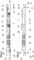
- eine Querstrebe mit dem Seilspeicher für das die beiden am Spanngurt angreifenden Seiltrume bildenden Seil in einem Längsschnitt in einem größeren Maßstab und
- Fig. 3
- die Querstrebe nach der
Fig. 2 in einer Draufsicht. - In der
Fig. 1 ist ein Fahrzeug 1 mit einer Ladefläche 2 und einem Fahrzeugaufbau 3 dargestellt, der zwei einander gegenüberliegende Längswände 4, 5 und eine die Längswände 4, 5 verbindende Decke 6 umfasst. Dieser Fahrzeugaufbau 3 kann vorzugsweise ein Planengestell für eine die Längswände 4, 5 und die Decke 6 bildende Plane aufweisen, die im Bereich der Decke 6 auf Querstreben 7 abgestützt ist. Das Beladen erfolgt auf einer Längsseite des Fahrzeugs 1, im dargestellten Ausführungsbeispiel durch die geöffnete Längswand 4. Das auf einer Palette 8 aufruhende Ladegut 9 wird mithilfe wenigstens eines Spanngurts 10 gesichert, der auf der der Ladeseite gegenüberliegenden Längsseite des Fahrzeugs 1 im Bereich der Längswand 5 an einem Anschlagpunkt 11 der Ladefläche 2 angeschlagen ist und über das Ladegut 9 auf die gegenüberliegende Längsseite der Ladefläche 2 geführt wird, um durch eine an einem dem Anschlagpunkt 11 gegenüberliegenden Anschlagpunkt 12 der Ladefläche 2 angreifende Spanneinrichtung 13 um das Ladegut festgezurrt zu werden. - Zum Freigeben des in dieser Weise gesicherten Ladeguts wird die Spanneinrichtung 13, beispielsweise ein Ratschenhebel, gelöst und das freie Ende des Spanngurts 10 aus der Spanneinrichtung 13 gezogen, sodass der Spanngurt 10 durch zwei an ihm angreifende Seiltrume 14 gegen die Decke 6 des Fahrzeugaufbaus 3 gezogen werden kann. Die Seiltrume 14, die an ihrem freien Ende mit Gurtrollen 15 versehen sind, über die der -Spanngurt 10 verläuft, sind um Umlenkrollen 16 im Endbereich einer hohl ausgebildeten Querstrebe 7 zu einem Seilspeicher 17 geführt, der einen in der Querstrebe 7 verschiebefest gehaltenen Seilrollensatz 18 und einen entlang der Querstrebe 7 verschiebbar gelagerten Seilrollensatz 19 umfasst, zwischen welchen Seilrollensätzen 18, 19 das mit seinen Enden die Seiltrume 14 bildende Seil 20 schalufenbildend hin- und hergeführt ist. Die Anordnung ist dabei so getroffen, dass der Seilrollensatz 19 in einem Schlitten 21 gelagert ist, der von einer in der Querstrebe angeordneten Zugfeder 22, vorzugsweise einer Schraubenfeder, im Sinne eines Einziehens der am Spanngurt 10 angreifenden Seiltrume 14 beaufschlagt wird.
- Die Querstrebe 7 ist vorzugsweise als U-Profil ausgebildet, zwischen dessen Schenkeln 23 die Umlenkrollen 16 für die Seiltrume 14, der Seilrollensatz 18 des Seilspeichers 17 gelagert sind und das feste Ende der Zugfeder 22 abgestützt ist. Gegenüber dem Laderaum werden die Zugfeder 22 und der Seilspeicher 17 sowie die Umlenkrollen 16 durch den die beiden Schenkel 23 verbindenden Steg 24 des U-Profils der Querstrebe 7 abgedeckt.
- Aufgrund des federbeaufschlagten Seilspeichers 17 wird der Spanngurt 10 nach einem Lösen von der Spanneinrichtung 13 in eine in
Fig. 1 strichpunktiert angedeutete Ausgangsstellung angehoben, in der der Spanngurt 10 unmittelbar unterhalb der Querstrebe 7 von der Längswand 5 zur Längswand 4 verläuft, und zwar um die Gurtrollen 15 der eingezogenen Seiltrume 14. Zum Festzurren eines Ladeguts braucht somit der Spanngurt 10 aus dieser Ausgangslage nur an seinem freien Ende erfasst und zur Spanneinrichtung 13 gezogen und dann mithilfe der Spanneinrichtung festgezurrt zu werden, sodass sich der Spanngurt 10 über das Ladegut 9 spannt und das Ladegut 9 an die Ladefläche 2 angedrückt gegen eine Verlagerung auf der Ladefläche 2 sichert. - Damit beim Lösen der Spanngurt 10 nicht durch die federbeaufschlagten Seiltrume 14 gegen die Decke 6 des Fahrzeugaufbaus nach oben unkontrolliert mitgenommen werden kann, ist den Umlenkrollen 16 für die Seiltrume 14 je eine Rücklaufbremse 25 zugeordnet. Diese Rücklaufbremse kann in einfacher Art durch einen Bremshebel 26 gebildet werden, der zwischen den Schenkeln 23 der Querstrebe 7 verschwenkbar gelagert ist und im Zulaufbereich der Seiltrume 14 an diesen anliegt. Da die Schwenkachse 27 der Bremshebel 26 oberhalb der Anlagestelle des Bremshebels 26 am Seiltrum 14 verläuft, wird bei einer Mitnahme eines Bremshebels 26 durch das anliegende Seiltrum 14 der Bremshebel 26 unter einer zunehmenden Verstärkung der Bremskraft gegen das Seiltrum 14 und die Umlenkrolle 16 verschwenkt, sodass der Einzug des Seiltrums 14 gestoppt wird. Bei einer Entlastung gibt der Bremshebel 26 das Seiltrum 14 wieder frei, sodass mit einer auf den Spanngurt 10 von Hand ausgeübten Rückhaltekraft der Spanngurt 10 sicher in die in
Fig. 1 strichpunktiert angedeutete Ausgangslage gebracht werden kann.
Claims (5)
- Fahrzeugaufbau mit einer Vorrichtung zur Ladegutsicherung, die einen an Anschlagpunkten (11, 12) auf einander gegenüberliegenden Längsseiten einer Ladefläche (2) angeschlagenen, mit einer Spanneinrichtung (13) versehenen Spanngurt (10) sowie eine Spanngurtführung umfasst, die zwei um Umlenkrollen (16) im Eckbereich zwischen den Längswänden (4, 5) und der Decke (6) des Fahrzeugaufbaus (3) aus einem Seilspeicher (17) gegen Federkraft ausziehbare, verschiebbar am Spanngurt (10) angreifende Seiltrume (14) aufweist, dadurch gekennzeichnet, dass die beiden Umlenkrollen (16) in einer hohlen Querstrebe (7) der Decke (6) gelagert sind, dass die Querstrebe (7) zwischen den beiden Umlenkrollen (16) eine Zugfeder (22) und den Seilspeicher (17) aufnimmt, der einen von der Zugfeder (22) beaufschlagten, entlang der Querstrebe (7) verschiebbaren und einen in der Querstrebe (7) verschiebefest gehaltenen Seilrollensatz (18, 19) besitzt, und dass die beiden Seiltrume (14) Endabschnitte eines Seils (20) bilden, das schlaufenbildend zwischen den beiden Seilrollensätzen (18, 19) hin- und hergeführt ist.
- Fahrzeugaufbau nach Anspruch 1, dadurch gekennzeichnet, dass die Querstrebe (7) ein U-Profil bildet.
- Fahrzeugaufbau nach Anspruch 1 oder 2, dadurch gekennzeichnet, dass die Zugfeder (22) als Schraubenfeder ausgebildet ist.
- Fahrzeugaufbau nach einem der Ansprüche 1 bis 3, dadurch gekennzeichnet, dass den beiden Umlenkrollen (16) je eine in Seileinzugsrichtung wirksame Rücklaufbremse (25) zugeordnet ist.
- Fahrzeugaufbau nach Anspruch 4, dadurch gekennzeichnet, dass die Rücklaufbremsen (25) einen im Zulaufbereich der Umlenkrolle (16) am Seiltrum (14) anliegenden Bremshebel (26) aufweisen.
Priority Applications (1)
| Application Number | Priority Date | Filing Date | Title |
|---|---|---|---|
| SI202030068T SI3770013T1 (sl) | 2019-07-25 | 2020-06-17 | Karoserija vozila z napravo za pritrditev tovora |
Applications Claiming Priority (1)
| Application Number | Priority Date | Filing Date | Title |
|---|---|---|---|
| ATA50678/2019A AT522184B1 (de) | 2019-07-25 | 2019-07-25 | Fahrzeugaufbau mit einer Vorrichtung zur Ladegutsicherung |
Publications (2)
| Publication Number | Publication Date |
|---|---|
| EP3770013A1 EP3770013A1 (de) | 2021-01-27 |
| EP3770013B1 true EP3770013B1 (de) | 2022-04-13 |
Family
ID=71105383
Family Applications (1)
| Application Number | Title | Priority Date | Filing Date |
|---|---|---|---|
| EP20180518.1A Active EP3770013B1 (de) | 2019-07-25 | 2020-06-17 | Fahrzeugaufbau mit einer vorrichtung zur ladegutsicherung |
Country Status (5)
| Country | Link |
|---|---|
| EP (1) | EP3770013B1 (de) |
| AT (1) | AT522184B1 (de) |
| HU (1) | HUE059461T2 (de) |
| PL (1) | PL3770013T3 (de) |
| SI (1) | SI3770013T1 (de) |
Families Citing this family (1)
| Publication number | Priority date | Publication date | Assignee | Title |
|---|---|---|---|---|
| FI130951B1 (fi) * | 2022-04-29 | 2024-06-14 | Simo Marttala Oy | Kiristin, kuljetusvälineen kuorman kiinnitysjärjestely ja kuljetusväline |
Family Cites Families (7)
| Publication number | Priority date | Publication date | Assignee | Title |
|---|---|---|---|---|
| DE10138771B4 (de) | 2001-05-23 | 2011-03-03 | Bpw Bergische Achsen Kg | System zur Sicherung einer Ladung |
| DE20109024U1 (de) | 2001-05-30 | 2001-09-20 | Schröder-Rentrop, Karl-Dieter, 58840 Plettenberg | Zurrgurtbereithaltesystem für Lkw-Aufbauten |
| GB2470582A (en) * | 2009-05-26 | 2010-12-01 | Lawrence David Ltd | Fastening arrangement for securing a load to a support surface |
| DE102010022855A1 (de) | 2010-06-07 | 2011-12-08 | Renate Fiolka | Fahrzeugaufbau mit einer Ladefläche und Zurrpunkten entlang der Ladefläche |
| DE102010035194A1 (de) * | 2010-08-24 | 2012-03-01 | Gm Global Technology Operations Llc (N.D.Ges.D. Staates Delaware) | Vorrichtung zum Sichern von Ladung eines Fahrzeuges |
| DE102014109217B4 (de) * | 2014-07-01 | 2024-11-07 | F. Hesterberg & Söhne Gmbh & Co. Kg | Vorrichtung zur Ladungssicherung in einem Nutzfahrzeug-Laderaum |
| DE102015101682A1 (de) * | 2015-02-05 | 2016-08-11 | F. Hesterberg & Söhne Gmbh & Co. Kg | Vorrichtung zum Sichern von Ladung in einem Laderaum eines Nutzfahrzeugs |
-
2019
- 2019-07-25 AT ATA50678/2019A patent/AT522184B1/de active
-
2020
- 2020-06-17 SI SI202030068T patent/SI3770013T1/sl unknown
- 2020-06-17 EP EP20180518.1A patent/EP3770013B1/de active Active
- 2020-06-17 HU HUE20180518A patent/HUE059461T2/hu unknown
- 2020-06-17 PL PL20180518.1T patent/PL3770013T3/pl unknown
Also Published As
| Publication number | Publication date |
|---|---|
| SI3770013T1 (sl) | 2022-08-31 |
| AT522184B1 (de) | 2020-09-15 |
| EP3770013A1 (de) | 2021-01-27 |
| AT522184A4 (de) | 2020-09-15 |
| PL3770013T3 (pl) | 2022-08-01 |
| HUE059461T2 (hu) | 2022-11-28 |
Similar Documents
| Publication | Publication Date | Title |
|---|---|---|
| DE10138771B4 (de) | System zur Sicherung einer Ladung | |
| AT522586B1 (de) | Fahrzeugaufbau mit einer Vorrichtung zur Ladegutsicherung | |
| EP3770013B1 (de) | Fahrzeugaufbau mit einer vorrichtung zur ladegutsicherung | |
| DE20109024U1 (de) | Zurrgurtbereithaltesystem für Lkw-Aufbauten | |
| DE102006023028B3 (de) | Funktionseinrichtung für einen Laderaum eines Kraftfahrzeugs | |
| DE102004037332B3 (de) | Spannvorrichtung für eine Gleitschutzkette | |
| DE1232480B (de) | Selbsttaetiger Gurtaufroller fuer Sicherheitsgurte | |
| DE3001410C2 (de) | Lastaufzug mit Teleskopschiene | |
| DE102017122247A1 (de) | Ladungssicherungssystem | |
| DE2736973A1 (de) | Verzurrgurt zum festzurren von objekten insbesondere in fahrzeugen | |
| DE202004003670U1 (de) | Sperrbalken | |
| EP1182082A1 (de) | Lösbares Befestigungssystem für Stückgut | |
| CH630319A5 (de) | Vierseilsystem einer fassaden-befahreinrichtung. | |
| DE102012005079B4 (de) | Vorrichtung zur Absturzsicherung, insbesondere von auf erhöhten Strukturen befindlichen Personen | |
| DE102013112432B4 (de) | Vorrichtung zum selbsttätigen Aushängen eines Anschlagmittels | |
| DE4335603A1 (de) | Vorrichtung zur Befestigung von Personenkraftwagen auf Autotransport-Fahrzeugen | |
| EP3293059A1 (de) | Rückhaltevorrichtung und rollstuhlrückhaltesystem mit einer derartigen rückhaltevorrichtung | |
| EP0187975B1 (de) | Lastaufzug, insbesondere Schrägaufzug mit einer aus mehreren Teleskopschüssen zusammengesetzten Schiene | |
| DE1091724B (de) | Kran od. dgl. mit teleskopartig ausziehbarer Saeule | |
| AT5619U1 (de) | Lastfahrzeug zum transportieren von blechbunden, insbesondere von spaltbändern | |
| AT409124B (de) | Seilausspulvorrichtung für das hub- bzw. zugseil eines seilkranes | |
| AT280343B (de) | Schleppbügel für Skilifte | |
| DE202006009855U1 (de) | Funktionseinrichtung für einen Laderaum eines Kraftfahrzeugs | |
| DE2807539A1 (de) | Spanneinrichtung | |
| DE917893C (de) | Schiffsladeeinrichtung |
Legal Events
| Date | Code | Title | Description |
|---|---|---|---|
| PUAI | Public reference made under article 153(3) epc to a published international application that has entered the european phase |
Free format text: ORIGINAL CODE: 0009012 |
|
| STAA | Information on the status of an ep patent application or granted ep patent |
Free format text: STATUS: THE APPLICATION HAS BEEN PUBLISHED |
|
| AK | Designated contracting states |
Kind code of ref document: A1 Designated state(s): AL AT BE BG CH CY CZ DE DK EE ES FI FR GB GR HR HU IE IS IT LI LT LU LV MC MK MT NL NO PL PT RO RS SE SI SK SM TR |
|
| AX | Request for extension of the european patent |
Extension state: BA ME |
|
| STAA | Information on the status of an ep patent application or granted ep patent |
Free format text: STATUS: REQUEST FOR EXAMINATION WAS MADE |
|
| 17P | Request for examination filed |
Effective date: 20210630 |
|
| RBV | Designated contracting states (corrected) |
Designated state(s): AL AT BE BG CH CY CZ DE DK EE ES FI FR GB GR HR HU IE IS IT LI LT LU LV MC MK MT NL NO PL PT RO RS SE SI SK SM TR |
|
| GRAP | Despatch of communication of intention to grant a patent |
Free format text: ORIGINAL CODE: EPIDOSNIGR1 |
|
| STAA | Information on the status of an ep patent application or granted ep patent |
Free format text: STATUS: GRANT OF PATENT IS INTENDED |
|
| RIC1 | Information provided on ipc code assigned before grant |
Ipc: B60P 7/08 20060101AFI20211025BHEP |
|
| INTG | Intention to grant announced |
Effective date: 20211125 |
|
| GRAS | Grant fee paid |
Free format text: ORIGINAL CODE: EPIDOSNIGR3 |
|
| GRAA | (expected) grant |
Free format text: ORIGINAL CODE: 0009210 |
|
| STAA | Information on the status of an ep patent application or granted ep patent |
Free format text: STATUS: THE PATENT HAS BEEN GRANTED |
|
| AK | Designated contracting states |
Kind code of ref document: B1 Designated state(s): AL AT BE BG CH CY CZ DE DK EE ES FI FR GB GR HR HU IE IS IT LI LT LU LV MC MK MT NL NO PL PT RO RS SE SI SK SM TR |
|
| REG | Reference to a national code |
Ref country code: GB Ref legal event code: FG4D Free format text: NOT ENGLISH |
|
| REG | Reference to a national code |
Ref country code: CH Ref legal event code: EP |
|
| REG | Reference to a national code |
Ref country code: DE Ref legal event code: R096 Ref document number: 502020000923 Country of ref document: DE |
|
| REG | Reference to a national code |
Ref country code: IE Ref legal event code: FG4D Free format text: LANGUAGE OF EP DOCUMENT: GERMAN |
|
| REG | Reference to a national code |
Ref country code: AT Ref legal event code: REF Ref document number: 1483154 Country of ref document: AT Kind code of ref document: T Effective date: 20220515 |
|
| REG | Reference to a national code |
Ref country code: RO Ref legal event code: EPE |
|
| REG | Reference to a national code |
Ref country code: LT Ref legal event code: MG9D |
|
| REG | Reference to a national code |
Ref country code: NL Ref legal event code: MP Effective date: 20220413 |
|
| PG25 | Lapsed in a contracting state [announced via postgrant information from national office to epo] |
Ref country code: NL Free format text: LAPSE BECAUSE OF FAILURE TO SUBMIT A TRANSLATION OF THE DESCRIPTION OR TO PAY THE FEE WITHIN THE PRESCRIBED TIME-LIMIT Effective date: 20220413 |
|
| PG25 | Lapsed in a contracting state [announced via postgrant information from national office to epo] |
Ref country code: SE Free format text: LAPSE BECAUSE OF FAILURE TO SUBMIT A TRANSLATION OF THE DESCRIPTION OR TO PAY THE FEE WITHIN THE PRESCRIBED TIME-LIMIT Effective date: 20220413 Ref country code: PT Free format text: LAPSE BECAUSE OF FAILURE TO SUBMIT A TRANSLATION OF THE DESCRIPTION OR TO PAY THE FEE WITHIN THE PRESCRIBED TIME-LIMIT Effective date: 20220816 Ref country code: NO Free format text: LAPSE BECAUSE OF FAILURE TO SUBMIT A TRANSLATION OF THE DESCRIPTION OR TO PAY THE FEE WITHIN THE PRESCRIBED TIME-LIMIT Effective date: 20220713 Ref country code: LT Free format text: LAPSE BECAUSE OF FAILURE TO SUBMIT A TRANSLATION OF THE DESCRIPTION OR TO PAY THE FEE WITHIN THE PRESCRIBED TIME-LIMIT Effective date: 20220413 Ref country code: HR Free format text: LAPSE BECAUSE OF FAILURE TO SUBMIT A TRANSLATION OF THE DESCRIPTION OR TO PAY THE FEE WITHIN THE PRESCRIBED TIME-LIMIT Effective date: 20220413 Ref country code: GR Free format text: LAPSE BECAUSE OF FAILURE TO SUBMIT A TRANSLATION OF THE DESCRIPTION OR TO PAY THE FEE WITHIN THE PRESCRIBED TIME-LIMIT Effective date: 20220714 Ref country code: FI Free format text: LAPSE BECAUSE OF FAILURE TO SUBMIT A TRANSLATION OF THE DESCRIPTION OR TO PAY THE FEE WITHIN THE PRESCRIBED TIME-LIMIT Effective date: 20220413 Ref country code: ES Free format text: LAPSE BECAUSE OF FAILURE TO SUBMIT A TRANSLATION OF THE DESCRIPTION OR TO PAY THE FEE WITHIN THE PRESCRIBED TIME-LIMIT Effective date: 20220413 Ref country code: BG Free format text: LAPSE BECAUSE OF FAILURE TO SUBMIT A TRANSLATION OF THE DESCRIPTION OR TO PAY THE FEE WITHIN THE PRESCRIBED TIME-LIMIT Effective date: 20220713 |
|
| REG | Reference to a national code |
Ref country code: HU Ref legal event code: AG4A Ref document number: E059461 Country of ref document: HU |
|
| PG25 | Lapsed in a contracting state [announced via postgrant information from national office to epo] |
Ref country code: RS Free format text: LAPSE BECAUSE OF FAILURE TO SUBMIT A TRANSLATION OF THE DESCRIPTION OR TO PAY THE FEE WITHIN THE PRESCRIBED TIME-LIMIT Effective date: 20220413 Ref country code: LV Free format text: LAPSE BECAUSE OF FAILURE TO SUBMIT A TRANSLATION OF THE DESCRIPTION OR TO PAY THE FEE WITHIN THE PRESCRIBED TIME-LIMIT Effective date: 20220413 Ref country code: IS Free format text: LAPSE BECAUSE OF FAILURE TO SUBMIT A TRANSLATION OF THE DESCRIPTION OR TO PAY THE FEE WITHIN THE PRESCRIBED TIME-LIMIT Effective date: 20220813 |
|
| REG | Reference to a national code |
Ref country code: DE Ref legal event code: R097 Ref document number: 502020000923 Country of ref document: DE |
|
| PG25 | Lapsed in a contracting state [announced via postgrant information from national office to epo] |
Ref country code: SM Free format text: LAPSE BECAUSE OF FAILURE TO SUBMIT A TRANSLATION OF THE DESCRIPTION OR TO PAY THE FEE WITHIN THE PRESCRIBED TIME-LIMIT Effective date: 20220413 Ref country code: MC Free format text: LAPSE BECAUSE OF FAILURE TO SUBMIT A TRANSLATION OF THE DESCRIPTION OR TO PAY THE FEE WITHIN THE PRESCRIBED TIME-LIMIT Effective date: 20220413 Ref country code: EE Free format text: LAPSE BECAUSE OF FAILURE TO SUBMIT A TRANSLATION OF THE DESCRIPTION OR TO PAY THE FEE WITHIN THE PRESCRIBED TIME-LIMIT Effective date: 20220413 Ref country code: DK Free format text: LAPSE BECAUSE OF FAILURE TO SUBMIT A TRANSLATION OF THE DESCRIPTION OR TO PAY THE FEE WITHIN THE PRESCRIBED TIME-LIMIT Effective date: 20220413 |
|
| PLBE | No opposition filed within time limit |
Free format text: ORIGINAL CODE: 0009261 |
|
| STAA | Information on the status of an ep patent application or granted ep patent |
Free format text: STATUS: NO OPPOSITION FILED WITHIN TIME LIMIT |
|
| REG | Reference to a national code |
Ref country code: BE Ref legal event code: MM Effective date: 20220630 |
|
| 26N | No opposition filed |
Effective date: 20230116 |
|
| PG25 | Lapsed in a contracting state [announced via postgrant information from national office to epo] |
Ref country code: AL Free format text: LAPSE BECAUSE OF FAILURE TO SUBMIT A TRANSLATION OF THE DESCRIPTION OR TO PAY THE FEE WITHIN THE PRESCRIBED TIME-LIMIT Effective date: 20220413 |
|
| PG25 | Lapsed in a contracting state [announced via postgrant information from national office to epo] |
Ref country code: LU Free format text: LAPSE BECAUSE OF NON-PAYMENT OF DUE FEES Effective date: 20220617 Ref country code: IE Free format text: LAPSE BECAUSE OF NON-PAYMENT OF DUE FEES Effective date: 20220617 |
|
| PG25 | Lapsed in a contracting state [announced via postgrant information from national office to epo] |
Ref country code: BE Free format text: LAPSE BECAUSE OF NON-PAYMENT OF DUE FEES Effective date: 20220630 |
|
| P01 | Opt-out of the competence of the unified patent court (upc) registered |
Effective date: 20230411 |
|
| PGFP | Annual fee paid to national office [announced via postgrant information from national office to epo] |
Ref country code: RO Payment date: 20230606 Year of fee payment: 4 Ref country code: FR Payment date: 20230622 Year of fee payment: 4 |
|
| PGFP | Annual fee paid to national office [announced via postgrant information from national office to epo] |
Ref country code: PL Payment date: 20230526 Year of fee payment: 4 |
|
| REG | Reference to a national code |
Ref country code: CH Ref legal event code: PL |
|
| PG25 | Lapsed in a contracting state [announced via postgrant information from national office to epo] |
Ref country code: MK Free format text: LAPSE BECAUSE OF FAILURE TO SUBMIT A TRANSLATION OF THE DESCRIPTION OR TO PAY THE FEE WITHIN THE PRESCRIBED TIME-LIMIT Effective date: 20220413 Ref country code: CY Free format text: LAPSE BECAUSE OF FAILURE TO SUBMIT A TRANSLATION OF THE DESCRIPTION OR TO PAY THE FEE WITHIN THE PRESCRIBED TIME-LIMIT Effective date: 20220413 Ref country code: CH Free format text: LAPSE BECAUSE OF NON-PAYMENT OF DUE FEES Effective date: 20230630 |
|
| PGFP | Annual fee paid to national office [announced via postgrant information from national office to epo] |
Ref country code: SK Payment date: 20240617 Year of fee payment: 5 |
|
| PGFP | Annual fee paid to national office [announced via postgrant information from national office to epo] |
Ref country code: SI Payment date: 20240613 Year of fee payment: 5 |
|
| PGFP | Annual fee paid to national office [announced via postgrant information from national office to epo] |
Ref country code: HU Payment date: 20240618 Year of fee payment: 5 |
|
| PG25 | Lapsed in a contracting state [announced via postgrant information from national office to epo] |
Ref country code: MT Free format text: LAPSE BECAUSE OF FAILURE TO SUBMIT A TRANSLATION OF THE DESCRIPTION OR TO PAY THE FEE WITHIN THE PRESCRIBED TIME-LIMIT Effective date: 20220413 |
|
| PGFP | Annual fee paid to national office [announced via postgrant information from national office to epo] |
Ref country code: IT Payment date: 20240619 Year of fee payment: 5 |
|
| PG25 | Lapsed in a contracting state [announced via postgrant information from national office to epo] |
Ref country code: BG Free format text: LAPSE BECAUSE OF FAILURE TO SUBMIT A TRANSLATION OF THE DESCRIPTION OR TO PAY THE FEE WITHIN THE PRESCRIBED TIME-LIMIT Effective date: 20220413 |
|
| PG25 | Lapsed in a contracting state [announced via postgrant information from national office to epo] |
Ref country code: BG Free format text: LAPSE BECAUSE OF FAILURE TO SUBMIT A TRANSLATION OF THE DESCRIPTION OR TO PAY THE FEE WITHIN THE PRESCRIBED TIME-LIMIT Effective date: 20220413 |
|
| PG25 | Lapsed in a contracting state [announced via postgrant information from national office to epo] |
Ref country code: RO Free format text: LAPSE BECAUSE OF NON-PAYMENT OF DUE FEES Effective date: 20240617 |
|
| PG25 | Lapsed in a contracting state [announced via postgrant information from national office to epo] |
Ref country code: RO Free format text: LAPSE BECAUSE OF NON-PAYMENT OF DUE FEES Effective date: 20240617 |
|
| GBPC | Gb: european patent ceased through non-payment of renewal fee |
Effective date: 20240617 |
|
| PG25 | Lapsed in a contracting state [announced via postgrant information from national office to epo] |
Ref country code: FR Free format text: LAPSE BECAUSE OF NON-PAYMENT OF DUE FEES Effective date: 20240630 |
|
| PG25 | Lapsed in a contracting state [announced via postgrant information from national office to epo] |
Ref country code: GB Free format text: LAPSE BECAUSE OF NON-PAYMENT OF DUE FEES Effective date: 20240617 |
|
| PGFP | Annual fee paid to national office [announced via postgrant information from national office to epo] |
Ref country code: DE Payment date: 20250624 Year of fee payment: 6 |
|
| PGFP | Annual fee paid to national office [announced via postgrant information from national office to epo] |
Ref country code: AT Payment date: 20250624 Year of fee payment: 6 |
|
| PGFP | Annual fee paid to national office [announced via postgrant information from national office to epo] |
Ref country code: CZ Payment date: 20250603 Year of fee payment: 6 |
|
| PG25 | Lapsed in a contracting state [announced via postgrant information from national office to epo] |
Ref country code: PL Free format text: LAPSE BECAUSE OF NON-PAYMENT OF DUE FEES Effective date: 20240617 |
|
| PG25 | Lapsed in a contracting state [announced via postgrant information from national office to epo] |
Ref country code: TR Free format text: LAPSE BECAUSE OF FAILURE TO SUBMIT A TRANSLATION OF THE DESCRIPTION OR TO PAY THE FEE WITHIN THE PRESCRIBED TIME-LIMIT Effective date: 20220413 |
|
| REG | Reference to a national code |
Ref country code: SK Ref legal event code: MM4A Ref document number: E 40023 Country of ref document: SK Effective date: 20250617 |
|
| PG25 | Lapsed in a contracting state [announced via postgrant information from national office to epo] |
Ref country code: HU Free format text: LAPSE BECAUSE OF NON-PAYMENT OF DUE FEES Effective date: 20250618 |
|
| PG25 | Lapsed in a contracting state [announced via postgrant information from national office to epo] |
Ref country code: IT Free format text: LAPSE BECAUSE OF NON-PAYMENT OF DUE FEES Effective date: 20250617 |
|
| PG25 | Lapsed in a contracting state [announced via postgrant information from national office to epo] |
Ref country code: SK Free format text: LAPSE BECAUSE OF NON-PAYMENT OF DUE FEES Effective date: 20250617 |