EP3769926A1 - Schaum-in-beutel-systeme und komponenten davon - Google Patents
Schaum-in-beutel-systeme und komponenten davon Download PDFInfo
- Publication number
- EP3769926A1 EP3769926A1 EP20194078.0A EP20194078A EP3769926A1 EP 3769926 A1 EP3769926 A1 EP 3769926A1 EP 20194078 A EP20194078 A EP 20194078A EP 3769926 A1 EP3769926 A1 EP 3769926A1
- Authority
- EP
- European Patent Office
- Prior art keywords
- foam
- arm
- film
- longitudinal sealer
- housing
- Prior art date
- Legal status (The legal status is an assumption and is not a legal conclusion. Google has not performed a legal analysis and makes no representation as to the accuracy of the status listed.)
- Withdrawn
Links
- 238000010438 heat treatment Methods 0.000 claims abstract description 99
- 239000012707 chemical precursor Substances 0.000 description 129
- 238000012546 transfer Methods 0.000 description 84
- 238000005086 pumping Methods 0.000 description 28
- 230000007246 mechanism Effects 0.000 description 24
- 238000004891 communication Methods 0.000 description 20
- 238000012545 processing Methods 0.000 description 17
- 239000006260 foam Substances 0.000 description 16
- 238000011144 upstream manufacturing Methods 0.000 description 16
- 230000033001 locomotion Effects 0.000 description 15
- 230000008901 benefit Effects 0.000 description 13
- 239000007788 liquid Substances 0.000 description 11
- 238000010586 diagram Methods 0.000 description 10
- 238000004590 computer program Methods 0.000 description 9
- 230000002093 peripheral effect Effects 0.000 description 9
- 230000006870 function Effects 0.000 description 8
- 238000003860 storage Methods 0.000 description 8
- 239000000463 material Substances 0.000 description 7
- 238000000034 method Methods 0.000 description 7
- 230000008859 change Effects 0.000 description 5
- 238000012423 maintenance Methods 0.000 description 5
- 238000013021 overheating Methods 0.000 description 5
- 230000037452 priming Effects 0.000 description 5
- 230000008569 process Effects 0.000 description 5
- 230000001012 protector Effects 0.000 description 5
- 239000000126 substance Substances 0.000 description 5
- 230000001360 synchronised effect Effects 0.000 description 5
- 229910052782 aluminium Inorganic materials 0.000 description 4
- XAGFODPZIPBFFR-UHFFFAOYSA-N aluminium Chemical compound [Al] XAGFODPZIPBFFR-UHFFFAOYSA-N 0.000 description 4
- 230000000712 assembly Effects 0.000 description 4
- 238000000429 assembly Methods 0.000 description 4
- 238000009530 blood pressure measurement Methods 0.000 description 4
- 230000001276 controlling effect Effects 0.000 description 4
- 230000007423 decrease Effects 0.000 description 4
- 239000012530 fluid Substances 0.000 description 4
- 239000002243 precursor Substances 0.000 description 4
- 238000007789 sealing Methods 0.000 description 4
- 230000001133 acceleration Effects 0.000 description 3
- 230000005540 biological transmission Effects 0.000 description 3
- 230000000740 bleeding effect Effects 0.000 description 3
- 230000006835 compression Effects 0.000 description 3
- 238000007906 compression Methods 0.000 description 3
- 239000013078 crystal Substances 0.000 description 3
- 239000012948 isocyanate Substances 0.000 description 3
- 230000003287 optical effect Effects 0.000 description 3
- 230000002572 peristaltic effect Effects 0.000 description 3
- 230000004044 response Effects 0.000 description 3
- 239000007787 solid Substances 0.000 description 3
- CURLTUGMZLYLDI-UHFFFAOYSA-N Carbon dioxide Chemical compound O=C=O CURLTUGMZLYLDI-UHFFFAOYSA-N 0.000 description 2
- 229920005830 Polyurethane Foam Polymers 0.000 description 2
- 229910000831 Steel Inorganic materials 0.000 description 2
- 238000003491 array Methods 0.000 description 2
- 239000003054 catalyst Substances 0.000 description 2
- 229910010293 ceramic material Inorganic materials 0.000 description 2
- 230000008878 coupling Effects 0.000 description 2
- 238000010168 coupling process Methods 0.000 description 2
- 238000005859 coupling reaction Methods 0.000 description 2
- 238000005520 cutting process Methods 0.000 description 2
- 230000007547 defect Effects 0.000 description 2
- 239000011521 glass Substances 0.000 description 2
- 125000002887 hydroxy group Chemical group [H]O* 0.000 description 2
- 150000002513 isocyanates Chemical class 0.000 description 2
- 239000000203 mixture Substances 0.000 description 2
- 238000004806 packaging method and process Methods 0.000 description 2
- 229920005862 polyol Polymers 0.000 description 2
- 150000003077 polyols Chemical class 0.000 description 2
- 229920002635 polyurethane Polymers 0.000 description 2
- 239000004814 polyurethane Substances 0.000 description 2
- 239000011496 polyurethane foam Substances 0.000 description 2
- 238000007639 printing Methods 0.000 description 2
- 238000013515 script Methods 0.000 description 2
- 229910052710 silicon Inorganic materials 0.000 description 2
- 239000010703 silicon Substances 0.000 description 2
- 239000010959 steel Substances 0.000 description 2
- XLYOFNOQVPJJNP-UHFFFAOYSA-N water Substances O XLYOFNOQVPJJNP-UHFFFAOYSA-N 0.000 description 2
- 239000004604 Blowing Agent Substances 0.000 description 1
- 241000258963 Diplopoda Species 0.000 description 1
- XUIMIQQOPSSXEZ-UHFFFAOYSA-N Silicon Chemical compound [Si] XUIMIQQOPSSXEZ-UHFFFAOYSA-N 0.000 description 1
- 238000005299 abrasion Methods 0.000 description 1
- 230000009471 action Effects 0.000 description 1
- 239000000654 additive Substances 0.000 description 1
- 238000013459 approach Methods 0.000 description 1
- 230000009286 beneficial effect Effects 0.000 description 1
- 230000015572 biosynthetic process Effects 0.000 description 1
- 238000007664 blowing Methods 0.000 description 1
- 238000004364 calculation method Methods 0.000 description 1
- 239000003990 capacitor Substances 0.000 description 1
- 229910002092 carbon dioxide Inorganic materials 0.000 description 1
- 239000001569 carbon dioxide Substances 0.000 description 1
- 210000003850 cellular structure Anatomy 0.000 description 1
- 238000004140 cleaning Methods 0.000 description 1
- 239000003086 colorant Substances 0.000 description 1
- 150000001875 compounds Chemical class 0.000 description 1
- 238000006073 displacement reaction Methods 0.000 description 1
- 230000009977 dual effect Effects 0.000 description 1
- 239000000835 fiber Substances 0.000 description 1
- 229920002457 flexible plastic Polymers 0.000 description 1
- 238000007667 floating Methods 0.000 description 1
- 238000005187 foaming Methods 0.000 description 1
- 239000004088 foaming agent Substances 0.000 description 1
- 231100001261 hazardous Toxicity 0.000 description 1
- 230000002706 hydrostatic effect Effects 0.000 description 1
- 230000006698 induction Effects 0.000 description 1
- 230000003993 interaction Effects 0.000 description 1
- -1 isocyanate compound Chemical class 0.000 description 1
- 230000007774 longterm Effects 0.000 description 1
- 230000001050 lubricating effect Effects 0.000 description 1
- 238000004519 manufacturing process Methods 0.000 description 1
- 230000013011 mating Effects 0.000 description 1
- 229910052751 metal Inorganic materials 0.000 description 1
- 239000002184 metal Substances 0.000 description 1
- 238000010295 mobile communication Methods 0.000 description 1
- 238000012544 monitoring process Methods 0.000 description 1
- 150000004767 nitrides Chemical class 0.000 description 1
- TWNQGVIAIRXVLR-UHFFFAOYSA-N oxo(oxoalumanyloxy)alumane Chemical compound O=[Al]O[Al]=O TWNQGVIAIRXVLR-UHFFFAOYSA-N 0.000 description 1
- 239000004033 plastic Substances 0.000 description 1
- 229920003023 plastic Polymers 0.000 description 1
- 239000002985 plastic film Substances 0.000 description 1
- 229920006255 plastic film Polymers 0.000 description 1
- 230000002035 prolonged effect Effects 0.000 description 1
- 230000001105 regulatory effect Effects 0.000 description 1
- 239000012858 resilient material Substances 0.000 description 1
- HBMJWWWQQXIZIP-UHFFFAOYSA-N silicon carbide Chemical compound [Si+]#[C-] HBMJWWWQQXIZIP-UHFFFAOYSA-N 0.000 description 1
- 229910010271 silicon carbide Inorganic materials 0.000 description 1
- 230000003068 static effect Effects 0.000 description 1
- 238000013519 translation Methods 0.000 description 1
- UONOETXJSWQNOL-UHFFFAOYSA-N tungsten carbide Chemical compound [W+]#[C-] UONOETXJSWQNOL-UHFFFAOYSA-N 0.000 description 1
- 238000013022 venting Methods 0.000 description 1
- 239000002699 waste material Substances 0.000 description 1
Images


Classifications
-
- B—PERFORMING OPERATIONS; TRANSPORTING
- B29—WORKING OF PLASTICS; WORKING OF SUBSTANCES IN A PLASTIC STATE IN GENERAL
- B29B—PREPARATION OR PRETREATMENT OF THE MATERIAL TO BE SHAPED; MAKING GRANULES OR PREFORMS; RECOVERY OF PLASTICS OR OTHER CONSTITUENTS OF WASTE MATERIAL CONTAINING PLASTICS
- B29B7/00—Mixing; Kneading
- B29B7/74—Mixing; Kneading using other mixers or combinations of mixers, e.g. of dissimilar mixers ; Plant
- B29B7/76—Mixers with stream-impingement mixing head
- B29B7/7631—Parts; Accessories
-
- B—PERFORMING OPERATIONS; TRANSPORTING
- B29—WORKING OF PLASTICS; WORKING OF SUBSTANCES IN A PLASTIC STATE IN GENERAL
- B29B—PREPARATION OR PRETREATMENT OF THE MATERIAL TO BE SHAPED; MAKING GRANULES OR PREFORMS; RECOVERY OF PLASTICS OR OTHER CONSTITUENTS OF WASTE MATERIAL CONTAINING PLASTICS
- B29B7/00—Mixing; Kneading
- B29B7/74—Mixing; Kneading using other mixers or combinations of mixers, e.g. of dissimilar mixers ; Plant
- B29B7/7404—Mixing devices specially adapted for foamable substances
-
- B—PERFORMING OPERATIONS; TRANSPORTING
- B01—PHYSICAL OR CHEMICAL PROCESSES OR APPARATUS IN GENERAL
- B01F—MIXING, e.g. DISSOLVING, EMULSIFYING OR DISPERSING
- B01F23/00—Mixing according to the phases to be mixed, e.g. dispersing or emulsifying
- B01F23/20—Mixing gases with liquids
- B01F23/29—Mixing systems, i.e. flow charts or diagrams
- B01F23/291—Mixing systems, i.e. flow charts or diagrams for obtaining foams or aerosols
-
- B—PERFORMING OPERATIONS; TRANSPORTING
- B01—PHYSICAL OR CHEMICAL PROCESSES OR APPARATUS IN GENERAL
- B01F—MIXING, e.g. DISSOLVING, EMULSIFYING OR DISPERSING
- B01F23/00—Mixing according to the phases to be mixed, e.g. dispersing or emulsifying
- B01F23/40—Mixing liquids with liquids; Emulsifying
- B01F23/49—Mixing systems, i.e. flow charts or diagrams
-
- B—PERFORMING OPERATIONS; TRANSPORTING
- B01—PHYSICAL OR CHEMICAL PROCESSES OR APPARATUS IN GENERAL
- B01F—MIXING, e.g. DISSOLVING, EMULSIFYING OR DISPERSING
- B01F23/00—Mixing according to the phases to be mixed, e.g. dispersing or emulsifying
- B01F23/70—Pre-treatment of the materials to be mixed
- B01F23/711—Heating materials, e.g. melting
-
- B—PERFORMING OPERATIONS; TRANSPORTING
- B01—PHYSICAL OR CHEMICAL PROCESSES OR APPARATUS IN GENERAL
- B01F—MIXING, e.g. DISSOLVING, EMULSIFYING OR DISPERSING
- B01F35/00—Accessories for mixers; Auxiliary operations or auxiliary devices; Parts or details of general application
- B01F35/181—Preventing generation of dust or dirt; Sieves; Filters
- B01F35/187—Preventing generation of dust or dirt; Sieves; Filters using filters in mixers, e.g. during venting
-
- B—PERFORMING OPERATIONS; TRANSPORTING
- B01—PHYSICAL OR CHEMICAL PROCESSES OR APPARATUS IN GENERAL
- B01F—MIXING, e.g. DISSOLVING, EMULSIFYING OR DISPERSING
- B01F35/00—Accessories for mixers; Auxiliary operations or auxiliary devices; Parts or details of general application
- B01F35/20—Measuring; Control or regulation
- B01F35/21—Measuring
- B01F35/211—Measuring of the operational parameters
- B01F35/2113—Pressure
-
- B—PERFORMING OPERATIONS; TRANSPORTING
- B01—PHYSICAL OR CHEMICAL PROCESSES OR APPARATUS IN GENERAL
- B01F—MIXING, e.g. DISSOLVING, EMULSIFYING OR DISPERSING
- B01F35/00—Accessories for mixers; Auxiliary operations or auxiliary devices; Parts or details of general application
- B01F35/20—Measuring; Control or regulation
- B01F35/21—Measuring
- B01F35/211—Measuring of the operational parameters
- B01F35/2115—Temperature
-
- B—PERFORMING OPERATIONS; TRANSPORTING
- B01—PHYSICAL OR CHEMICAL PROCESSES OR APPARATUS IN GENERAL
- B01F—MIXING, e.g. DISSOLVING, EMULSIFYING OR DISPERSING
- B01F35/00—Accessories for mixers; Auxiliary operations or auxiliary devices; Parts or details of general application
- B01F35/20—Measuring; Control or regulation
- B01F35/21—Measuring
- B01F35/214—Measuring characterised by the means for measuring
- B01F35/2144—Measuring characterised by the means for measuring using radiation for measuring the parameters of the mixture or components to be mixed
-
- B—PERFORMING OPERATIONS; TRANSPORTING
- B01—PHYSICAL OR CHEMICAL PROCESSES OR APPARATUS IN GENERAL
- B01F—MIXING, e.g. DISSOLVING, EMULSIFYING OR DISPERSING
- B01F35/00—Accessories for mixers; Auxiliary operations or auxiliary devices; Parts or details of general application
- B01F35/20—Measuring; Control or regulation
- B01F35/22—Control or regulation
- B01F35/2201—Control or regulation characterised by the type of control technique used
- B01F35/2209—Controlling the mixing process as a whole, i.e. involving a complete monitoring and controlling of the mixing process during the whole mixing cycle
-
- B—PERFORMING OPERATIONS; TRANSPORTING
- B01—PHYSICAL OR CHEMICAL PROCESSES OR APPARATUS IN GENERAL
- B01F—MIXING, e.g. DISSOLVING, EMULSIFYING OR DISPERSING
- B01F35/00—Accessories for mixers; Auxiliary operations or auxiliary devices; Parts or details of general application
- B01F35/20—Measuring; Control or regulation
- B01F35/22—Control or regulation
- B01F35/221—Control or regulation of operational parameters, e.g. level of material in the mixer, temperature or pressure
- B01F35/2215—Temperature
-
- B—PERFORMING OPERATIONS; TRANSPORTING
- B01—PHYSICAL OR CHEMICAL PROCESSES OR APPARATUS IN GENERAL
- B01F—MIXING, e.g. DISSOLVING, EMULSIFYING OR DISPERSING
- B01F35/00—Accessories for mixers; Auxiliary operations or auxiliary devices; Parts or details of general application
- B01F35/50—Mixing receptacles
- B01F35/513—Flexible receptacles, e.g. bags supported by rigid containers
-
- B—PERFORMING OPERATIONS; TRANSPORTING
- B01—PHYSICAL OR CHEMICAL PROCESSES OR APPARATUS IN GENERAL
- B01F—MIXING, e.g. DISSOLVING, EMULSIFYING OR DISPERSING
- B01F35/00—Accessories for mixers; Auxiliary operations or auxiliary devices; Parts or details of general application
- B01F35/71—Feed mechanisms
- B01F35/717—Feed mechanisms characterised by the means for feeding the components to the mixer
- B01F35/7176—Feed mechanisms characterised by the means for feeding the components to the mixer using pumps
-
- B—PERFORMING OPERATIONS; TRANSPORTING
- B01—PHYSICAL OR CHEMICAL PROCESSES OR APPARATUS IN GENERAL
- B01F—MIXING, e.g. DISSOLVING, EMULSIFYING OR DISPERSING
- B01F35/00—Accessories for mixers; Auxiliary operations or auxiliary devices; Parts or details of general application
- B01F35/71—Feed mechanisms
- B01F35/717—Feed mechanisms characterised by the means for feeding the components to the mixer
- B01F35/71805—Feed mechanisms characterised by the means for feeding the components to the mixer using valves, gates, orifices or openings
-
- B—PERFORMING OPERATIONS; TRANSPORTING
- B01—PHYSICAL OR CHEMICAL PROCESSES OR APPARATUS IN GENERAL
- B01F—MIXING, e.g. DISSOLVING, EMULSIFYING OR DISPERSING
- B01F35/00—Accessories for mixers; Auxiliary operations or auxiliary devices; Parts or details of general application
- B01F35/90—Heating or cooling systems
- B01F35/92—Heating or cooling systems for heating the outside of the receptacle, e.g. heated jackets or burners
-
- B—PERFORMING OPERATIONS; TRANSPORTING
- B29—WORKING OF PLASTICS; WORKING OF SUBSTANCES IN A PLASTIC STATE IN GENERAL
- B29B—PREPARATION OR PRETREATMENT OF THE MATERIAL TO BE SHAPED; MAKING GRANULES OR PREFORMS; RECOVERY OF PLASTICS OR OTHER CONSTITUENTS OF WASTE MATERIAL CONTAINING PLASTICS
- B29B7/00—Mixing; Kneading
- B29B7/30—Mixing; Kneading continuous, with mechanical mixing or kneading devices
- B29B7/58—Component parts, details or accessories; Auxiliary operations
- B29B7/72—Measuring, controlling or regulating
- B29B7/726—Measuring properties of mixture, e.g. temperature or density
-
- B—PERFORMING OPERATIONS; TRANSPORTING
- B29—WORKING OF PLASTICS; WORKING OF SUBSTANCES IN A PLASTIC STATE IN GENERAL
- B29B—PREPARATION OR PRETREATMENT OF THE MATERIAL TO BE SHAPED; MAKING GRANULES OR PREFORMS; RECOVERY OF PLASTICS OR OTHER CONSTITUENTS OF WASTE MATERIAL CONTAINING PLASTICS
- B29B7/00—Mixing; Kneading
- B29B7/30—Mixing; Kneading continuous, with mechanical mixing or kneading devices
- B29B7/58—Component parts, details or accessories; Auxiliary operations
- B29B7/72—Measuring, controlling or regulating
- B29B7/728—Measuring data of the driving system, e.g. torque, speed, power, vibration
-
- B—PERFORMING OPERATIONS; TRANSPORTING
- B29—WORKING OF PLASTICS; WORKING OF SUBSTANCES IN A PLASTIC STATE IN GENERAL
- B29B—PREPARATION OR PRETREATMENT OF THE MATERIAL TO BE SHAPED; MAKING GRANULES OR PREFORMS; RECOVERY OF PLASTICS OR OTHER CONSTITUENTS OF WASTE MATERIAL CONTAINING PLASTICS
- B29B7/00—Mixing; Kneading
- B29B7/74—Mixing; Kneading using other mixers or combinations of mixers, e.g. of dissimilar mixers ; Plant
- B29B7/76—Mixers with stream-impingement mixing head
- B29B7/7615—Mixers with stream-impingement mixing head characterised by arrangements for controlling, measuring or regulating, e.g. for feeding or proportioning the components
-
- B—PERFORMING OPERATIONS; TRANSPORTING
- B29—WORKING OF PLASTICS; WORKING OF SUBSTANCES IN A PLASTIC STATE IN GENERAL
- B29B—PREPARATION OR PRETREATMENT OF THE MATERIAL TO BE SHAPED; MAKING GRANULES OR PREFORMS; RECOVERY OF PLASTICS OR OTHER CONSTITUENTS OF WASTE MATERIAL CONTAINING PLASTICS
- B29B7/00—Mixing; Kneading
- B29B7/74—Mixing; Kneading using other mixers or combinations of mixers, e.g. of dissimilar mixers ; Plant
- B29B7/76—Mixers with stream-impingement mixing head
- B29B7/7631—Parts; Accessories
- B29B7/7652—Construction of the discharge orifice, opening or nozzle
- B29B7/7657—Adjustable discharge orifices, openings or nozzle openings, e.g. for controlling the rate of dispensing
-
- B—PERFORMING OPERATIONS; TRANSPORTING
- B29—WORKING OF PLASTICS; WORKING OF SUBSTANCES IN A PLASTIC STATE IN GENERAL
- B29B—PREPARATION OR PRETREATMENT OF THE MATERIAL TO BE SHAPED; MAKING GRANULES OR PREFORMS; RECOVERY OF PLASTICS OR OTHER CONSTITUENTS OF WASTE MATERIAL CONTAINING PLASTICS
- B29B7/00—Mixing; Kneading
- B29B7/74—Mixing; Kneading using other mixers or combinations of mixers, e.g. of dissimilar mixers ; Plant
- B29B7/76—Mixers with stream-impingement mixing head
- B29B7/7663—Mixers with stream-impingement mixing head the mixing head having an outlet tube with a reciprocating plunger, e.g. with the jets impinging in the tube
- B29B7/7684—Parts; Accessories
- B29B7/7689—Plunger constructions
-
- B—PERFORMING OPERATIONS; TRANSPORTING
- B29—WORKING OF PLASTICS; WORKING OF SUBSTANCES IN A PLASTIC STATE IN GENERAL
- B29B—PREPARATION OR PRETREATMENT OF THE MATERIAL TO BE SHAPED; MAKING GRANULES OR PREFORMS; RECOVERY OF PLASTICS OR OTHER CONSTITUENTS OF WASTE MATERIAL CONTAINING PLASTICS
- B29B7/00—Mixing; Kneading
- B29B7/80—Component parts, details or accessories; Auxiliary operations
- B29B7/82—Heating or cooling
- B29B7/823—Temperature control
-
- B—PERFORMING OPERATIONS; TRANSPORTING
- B29—WORKING OF PLASTICS; WORKING OF SUBSTANCES IN A PLASTIC STATE IN GENERAL
- B29B—PREPARATION OR PRETREATMENT OF THE MATERIAL TO BE SHAPED; MAKING GRANULES OR PREFORMS; RECOVERY OF PLASTICS OR OTHER CONSTITUENTS OF WASTE MATERIAL CONTAINING PLASTICS
- B29B7/00—Mixing; Kneading
- B29B7/80—Component parts, details or accessories; Auxiliary operations
- B29B7/82—Heating or cooling
- B29B7/826—Apparatus therefor
-
- B—PERFORMING OPERATIONS; TRANSPORTING
- B29—WORKING OF PLASTICS; WORKING OF SUBSTANCES IN A PLASTIC STATE IN GENERAL
- B29C—SHAPING OR JOINING OF PLASTICS; SHAPING OF MATERIAL IN A PLASTIC STATE, NOT OTHERWISE PROVIDED FOR; AFTER-TREATMENT OF THE SHAPED PRODUCTS, e.g. REPAIRING
- B29C44/00—Shaping by internal pressure generated in the material, e.g. swelling or foaming ; Producing porous or cellular expanded plastics articles
- B29C44/02—Shaping by internal pressure generated in the material, e.g. swelling or foaming ; Producing porous or cellular expanded plastics articles for articles of definite length, i.e. discrete articles
- B29C44/12—Incorporating or moulding on preformed parts, e.g. inserts or reinforcements
- B29C44/18—Filling preformed cavities
- B29C44/182—Filling flexible bags not having a particular shape
-
- B—PERFORMING OPERATIONS; TRANSPORTING
- B29—WORKING OF PLASTICS; WORKING OF SUBSTANCES IN A PLASTIC STATE IN GENERAL
- B29C—SHAPING OR JOINING OF PLASTICS; SHAPING OF MATERIAL IN A PLASTIC STATE, NOT OTHERWISE PROVIDED FOR; AFTER-TREATMENT OF THE SHAPED PRODUCTS, e.g. REPAIRING
- B29C44/00—Shaping by internal pressure generated in the material, e.g. swelling or foaming ; Producing porous or cellular expanded plastics articles
- B29C44/34—Auxiliary operations
- B29C44/3442—Mixing, kneading or conveying the foamable material
-
- B—PERFORMING OPERATIONS; TRANSPORTING
- B29—WORKING OF PLASTICS; WORKING OF SUBSTANCES IN A PLASTIC STATE IN GENERAL
- B29C—SHAPING OR JOINING OF PLASTICS; SHAPING OF MATERIAL IN A PLASTIC STATE, NOT OTHERWISE PROVIDED FOR; AFTER-TREATMENT OF THE SHAPED PRODUCTS, e.g. REPAIRING
- B29C65/00—Joining or sealing of preformed parts, e.g. welding of plastics materials; Apparatus therefor
- B29C65/02—Joining or sealing of preformed parts, e.g. welding of plastics materials; Apparatus therefor by heating, with or without pressure
- B29C65/18—Joining or sealing of preformed parts, e.g. welding of plastics materials; Apparatus therefor by heating, with or without pressure using heated tools
- B29C65/22—Heated wire resistive ribbon, resistive band or resistive strip
- B29C65/228—Heated wire resistive ribbon, resistive band or resistive strip characterised by the means for electrically connecting the ends of said heated wire, resistive ribbon, resistive band or resistive strip
-
- B—PERFORMING OPERATIONS; TRANSPORTING
- B29—WORKING OF PLASTICS; WORKING OF SUBSTANCES IN A PLASTIC STATE IN GENERAL
- B29C—SHAPING OR JOINING OF PLASTICS; SHAPING OF MATERIAL IN A PLASTIC STATE, NOT OTHERWISE PROVIDED FOR; AFTER-TREATMENT OF THE SHAPED PRODUCTS, e.g. REPAIRING
- B29C65/00—Joining or sealing of preformed parts, e.g. welding of plastics materials; Apparatus therefor
- B29C65/02—Joining or sealing of preformed parts, e.g. welding of plastics materials; Apparatus therefor by heating, with or without pressure
- B29C65/18—Joining or sealing of preformed parts, e.g. welding of plastics materials; Apparatus therefor by heating, with or without pressure using heated tools
- B29C65/24—Joining or sealing of preformed parts, e.g. welding of plastics materials; Apparatus therefor by heating, with or without pressure using heated tools characterised by the means for heating the tool
- B29C65/30—Electrical means
-
- B—PERFORMING OPERATIONS; TRANSPORTING
- B29—WORKING OF PLASTICS; WORKING OF SUBSTANCES IN A PLASTIC STATE IN GENERAL
- B29C—SHAPING OR JOINING OF PLASTICS; SHAPING OF MATERIAL IN A PLASTIC STATE, NOT OTHERWISE PROVIDED FOR; AFTER-TREATMENT OF THE SHAPED PRODUCTS, e.g. REPAIRING
- B29C65/00—Joining or sealing of preformed parts, e.g. welding of plastics materials; Apparatus therefor
- B29C65/74—Joining or sealing of preformed parts, e.g. welding of plastics materials; Apparatus therefor by welding and severing, or by joining and severing, the severing being performed in the area to be joined, next to the area to be joined, in the joint area or next to the joint area
- B29C65/745—Joining or sealing of preformed parts, e.g. welding of plastics materials; Apparatus therefor by welding and severing, or by joining and severing, the severing being performed in the area to be joined, next to the area to be joined, in the joint area or next to the joint area using a single unit having both a severing tool and a welding tool
- B29C65/7453—Joining or sealing of preformed parts, e.g. welding of plastics materials; Apparatus therefor by welding and severing, or by joining and severing, the severing being performed in the area to be joined, next to the area to be joined, in the joint area or next to the joint area using a single unit having both a severing tool and a welding tool the severing tool being a wire
-
- B—PERFORMING OPERATIONS; TRANSPORTING
- B29—WORKING OF PLASTICS; WORKING OF SUBSTANCES IN A PLASTIC STATE IN GENERAL
- B29C—SHAPING OR JOINING OF PLASTICS; SHAPING OF MATERIAL IN A PLASTIC STATE, NOT OTHERWISE PROVIDED FOR; AFTER-TREATMENT OF THE SHAPED PRODUCTS, e.g. REPAIRING
- B29C66/00—General aspects of processes or apparatus for joining preformed parts
- B29C66/004—Preventing sticking together, e.g. of some areas of the parts to be joined
- B29C66/0042—Preventing sticking together, e.g. of some areas of the parts to be joined of the joining tool and the parts to be joined
- B29C66/0044—Preventing sticking together, e.g. of some areas of the parts to be joined of the joining tool and the parts to be joined using a separating sheet, e.g. fixed on the joining tool
-
- B—PERFORMING OPERATIONS; TRANSPORTING
- B29—WORKING OF PLASTICS; WORKING OF SUBSTANCES IN A PLASTIC STATE IN GENERAL
- B29C—SHAPING OR JOINING OF PLASTICS; SHAPING OF MATERIAL IN A PLASTIC STATE, NOT OTHERWISE PROVIDED FOR; AFTER-TREATMENT OF THE SHAPED PRODUCTS, e.g. REPAIRING
- B29C66/00—General aspects of processes or apparatus for joining preformed parts
- B29C66/006—Preventing damaging, e.g. of the parts to be joined
- B29C66/0062—Preventing damaging, e.g. of the parts to be joined of the joining tool, e.g. avoiding wear of the joining tool
-
- B—PERFORMING OPERATIONS; TRANSPORTING
- B29—WORKING OF PLASTICS; WORKING OF SUBSTANCES IN A PLASTIC STATE IN GENERAL
- B29C—SHAPING OR JOINING OF PLASTICS; SHAPING OF MATERIAL IN A PLASTIC STATE, NOT OTHERWISE PROVIDED FOR; AFTER-TREATMENT OF THE SHAPED PRODUCTS, e.g. REPAIRING
- B29C66/00—General aspects of processes or apparatus for joining preformed parts
- B29C66/01—General aspects dealing with the joint area or with the area to be joined
- B29C66/05—Particular design of joint configurations
- B29C66/10—Particular design of joint configurations particular design of the joint cross-sections
- B29C66/11—Joint cross-sections comprising a single joint-segment, i.e. one of the parts to be joined comprising a single joint-segment in the joint cross-section
- B29C66/112—Single lapped joints
- B29C66/1122—Single lap to lap joints, i.e. overlap joints
-
- B—PERFORMING OPERATIONS; TRANSPORTING
- B29—WORKING OF PLASTICS; WORKING OF SUBSTANCES IN A PLASTIC STATE IN GENERAL
- B29C—SHAPING OR JOINING OF PLASTICS; SHAPING OF MATERIAL IN A PLASTIC STATE, NOT OTHERWISE PROVIDED FOR; AFTER-TREATMENT OF THE SHAPED PRODUCTS, e.g. REPAIRING
- B29C66/00—General aspects of processes or apparatus for joining preformed parts
- B29C66/01—General aspects dealing with the joint area or with the area to be joined
- B29C66/05—Particular design of joint configurations
- B29C66/20—Particular design of joint configurations particular design of the joint lines, e.g. of the weld lines
- B29C66/23—Particular design of joint configurations particular design of the joint lines, e.g. of the weld lines said joint lines being multiple and parallel or being in the form of tessellations
- B29C66/232—Particular design of joint configurations particular design of the joint lines, e.g. of the weld lines said joint lines being multiple and parallel or being in the form of tessellations said joint lines being multiple and parallel, i.e. the joint being formed by several parallel joint lines
-
- B—PERFORMING OPERATIONS; TRANSPORTING
- B29—WORKING OF PLASTICS; WORKING OF SUBSTANCES IN A PLASTIC STATE IN GENERAL
- B29C—SHAPING OR JOINING OF PLASTICS; SHAPING OF MATERIAL IN A PLASTIC STATE, NOT OTHERWISE PROVIDED FOR; AFTER-TREATMENT OF THE SHAPED PRODUCTS, e.g. REPAIRING
- B29C66/00—General aspects of processes or apparatus for joining preformed parts
- B29C66/40—General aspects of joining substantially flat articles, e.g. plates, sheets or web-like materials; Making flat seams in tubular or hollow articles; Joining single elements to substantially flat surfaces
- B29C66/41—Joining substantially flat articles ; Making flat seams in tubular or hollow articles
- B29C66/43—Joining a relatively small portion of the surface of said articles
- B29C66/431—Joining the articles to themselves
- B29C66/4312—Joining the articles to themselves for making flat seams in tubular or hollow articles, e.g. transversal seams
-
- B—PERFORMING OPERATIONS; TRANSPORTING
- B29—WORKING OF PLASTICS; WORKING OF SUBSTANCES IN A PLASTIC STATE IN GENERAL
- B29C—SHAPING OR JOINING OF PLASTICS; SHAPING OF MATERIAL IN A PLASTIC STATE, NOT OTHERWISE PROVIDED FOR; AFTER-TREATMENT OF THE SHAPED PRODUCTS, e.g. REPAIRING
- B29C66/00—General aspects of processes or apparatus for joining preformed parts
- B29C66/40—General aspects of joining substantially flat articles, e.g. plates, sheets or web-like materials; Making flat seams in tubular or hollow articles; Joining single elements to substantially flat surfaces
- B29C66/41—Joining substantially flat articles ; Making flat seams in tubular or hollow articles
- B29C66/43—Joining a relatively small portion of the surface of said articles
- B29C66/432—Joining a relatively small portion of the surface of said articles for making tubular articles or closed loops, e.g. by joining several sheets ; for making hollow articles or hollow preforms
-
- B—PERFORMING OPERATIONS; TRANSPORTING
- B29—WORKING OF PLASTICS; WORKING OF SUBSTANCES IN A PLASTIC STATE IN GENERAL
- B29C—SHAPING OR JOINING OF PLASTICS; SHAPING OF MATERIAL IN A PLASTIC STATE, NOT OTHERWISE PROVIDED FOR; AFTER-TREATMENT OF THE SHAPED PRODUCTS, e.g. REPAIRING
- B29C66/00—General aspects of processes or apparatus for joining preformed parts
- B29C66/80—General aspects of machine operations or constructions and parts thereof
- B29C66/81—General aspects of the pressing elements, i.e. the elements applying pressure on the parts to be joined in the area to be joined, e.g. the welding jaws or clamps
- B29C66/816—General aspects of the pressing elements, i.e. the elements applying pressure on the parts to be joined in the area to be joined, e.g. the welding jaws or clamps characterised by the mounting of the pressing elements, e.g. of the welding jaws or clamps
- B29C66/8167—Quick change joining tools or surfaces
-
- B—PERFORMING OPERATIONS; TRANSPORTING
- B29—WORKING OF PLASTICS; WORKING OF SUBSTANCES IN A PLASTIC STATE IN GENERAL
- B29C—SHAPING OR JOINING OF PLASTICS; SHAPING OF MATERIAL IN A PLASTIC STATE, NOT OTHERWISE PROVIDED FOR; AFTER-TREATMENT OF THE SHAPED PRODUCTS, e.g. REPAIRING
- B29C66/00—General aspects of processes or apparatus for joining preformed parts
- B29C66/80—General aspects of machine operations or constructions and parts thereof
- B29C66/82—Pressure application arrangements, e.g. transmission or actuating mechanisms for joining tools or clamps
- B29C66/822—Transmission mechanisms
- B29C66/8225—Crank mechanisms
-
- B—PERFORMING OPERATIONS; TRANSPORTING
- B29—WORKING OF PLASTICS; WORKING OF SUBSTANCES IN A PLASTIC STATE IN GENERAL
- B29C—SHAPING OR JOINING OF PLASTICS; SHAPING OF MATERIAL IN A PLASTIC STATE, NOT OTHERWISE PROVIDED FOR; AFTER-TREATMENT OF THE SHAPED PRODUCTS, e.g. REPAIRING
- B29C66/00—General aspects of processes or apparatus for joining preformed parts
- B29C66/80—General aspects of machine operations or constructions and parts thereof
- B29C66/83—General aspects of machine operations or constructions and parts thereof characterised by the movement of the joining or pressing tools
- B29C66/832—Reciprocating joining or pressing tools
- B29C66/8322—Joining or pressing tools reciprocating along one axis
-
- B—PERFORMING OPERATIONS; TRANSPORTING
- B29—WORKING OF PLASTICS; WORKING OF SUBSTANCES IN A PLASTIC STATE IN GENERAL
- B29C—SHAPING OR JOINING OF PLASTICS; SHAPING OF MATERIAL IN A PLASTIC STATE, NOT OTHERWISE PROVIDED FOR; AFTER-TREATMENT OF THE SHAPED PRODUCTS, e.g. REPAIRING
- B29C66/00—General aspects of processes or apparatus for joining preformed parts
- B29C66/80—General aspects of machine operations or constructions and parts thereof
- B29C66/83—General aspects of machine operations or constructions and parts thereof characterised by the movement of the joining or pressing tools
- B29C66/834—General aspects of machine operations or constructions and parts thereof characterised by the movement of the joining or pressing tools moving with the parts to be joined
- B29C66/8341—Roller, cylinder or drum types; Band or belt types; Ball types
- B29C66/83411—Roller, cylinder or drum types
- B29C66/83413—Roller, cylinder or drum types cooperating rollers, cylinders or drums
-
- B—PERFORMING OPERATIONS; TRANSPORTING
- B29—WORKING OF PLASTICS; WORKING OF SUBSTANCES IN A PLASTIC STATE IN GENERAL
- B29C—SHAPING OR JOINING OF PLASTICS; SHAPING OF MATERIAL IN A PLASTIC STATE, NOT OTHERWISE PROVIDED FOR; AFTER-TREATMENT OF THE SHAPED PRODUCTS, e.g. REPAIRING
- B29C66/00—General aspects of processes or apparatus for joining preformed parts
- B29C66/80—General aspects of machine operations or constructions and parts thereof
- B29C66/84—Specific machine types or machines suitable for specific applications
- B29C66/849—Packaging machines
-
- B—PERFORMING OPERATIONS; TRANSPORTING
- B29—WORKING OF PLASTICS; WORKING OF SUBSTANCES IN A PLASTIC STATE IN GENERAL
- B29C—SHAPING OR JOINING OF PLASTICS; SHAPING OF MATERIAL IN A PLASTIC STATE, NOT OTHERWISE PROVIDED FOR; AFTER-TREATMENT OF THE SHAPED PRODUCTS, e.g. REPAIRING
- B29C66/00—General aspects of processes or apparatus for joining preformed parts
- B29C66/80—General aspects of machine operations or constructions and parts thereof
- B29C66/84—Specific machine types or machines suitable for specific applications
- B29C66/851—Bag or container making machines
- B29C66/8511—Bag making machines
-
- B—PERFORMING OPERATIONS; TRANSPORTING
- B29—WORKING OF PLASTICS; WORKING OF SUBSTANCES IN A PLASTIC STATE IN GENERAL
- B29C—SHAPING OR JOINING OF PLASTICS; SHAPING OF MATERIAL IN A PLASTIC STATE, NOT OTHERWISE PROVIDED FOR; AFTER-TREATMENT OF THE SHAPED PRODUCTS, e.g. REPAIRING
- B29C66/00—General aspects of processes or apparatus for joining preformed parts
- B29C66/80—General aspects of machine operations or constructions and parts thereof
- B29C66/84—Specific machine types or machines suitable for specific applications
- B29C66/865—Independently movable welding apparatus, e.g. on wheels
-
- B—PERFORMING OPERATIONS; TRANSPORTING
- B29—WORKING OF PLASTICS; WORKING OF SUBSTANCES IN A PLASTIC STATE IN GENERAL
- B29C—SHAPING OR JOINING OF PLASTICS; SHAPING OF MATERIAL IN A PLASTIC STATE, NOT OTHERWISE PROVIDED FOR; AFTER-TREATMENT OF THE SHAPED PRODUCTS, e.g. REPAIRING
- B29C66/00—General aspects of processes or apparatus for joining preformed parts
- B29C66/80—General aspects of machine operations or constructions and parts thereof
- B29C66/87—Auxiliary operations or devices
- B29C66/874—Safety measures or devices
- B29C66/8742—Safety measures or devices for operators
-
- B—PERFORMING OPERATIONS; TRANSPORTING
- B29—WORKING OF PLASTICS; WORKING OF SUBSTANCES IN A PLASTIC STATE IN GENERAL
- B29C—SHAPING OR JOINING OF PLASTICS; SHAPING OF MATERIAL IN A PLASTIC STATE, NOT OTHERWISE PROVIDED FOR; AFTER-TREATMENT OF THE SHAPED PRODUCTS, e.g. REPAIRING
- B29C66/00—General aspects of processes or apparatus for joining preformed parts
- B29C66/80—General aspects of machine operations or constructions and parts thereof
- B29C66/87—Auxiliary operations or devices
- B29C66/874—Safety measures or devices
- B29C66/8744—Preventing overheating of the parts to be joined, e.g. if the machine stops or slows down
- B29C66/87443—Preventing overheating of the parts to be joined, e.g. if the machine stops or slows down by withdrawing the heating tools
-
- B—PERFORMING OPERATIONS; TRANSPORTING
- B29—WORKING OF PLASTICS; WORKING OF SUBSTANCES IN A PLASTIC STATE IN GENERAL
- B29C—SHAPING OR JOINING OF PLASTICS; SHAPING OF MATERIAL IN A PLASTIC STATE, NOT OTHERWISE PROVIDED FOR; AFTER-TREATMENT OF THE SHAPED PRODUCTS, e.g. REPAIRING
- B29C66/00—General aspects of processes or apparatus for joining preformed parts
- B29C66/80—General aspects of machine operations or constructions and parts thereof
- B29C66/87—Auxiliary operations or devices
- B29C66/876—Maintenance or cleaning
-
- B—PERFORMING OPERATIONS; TRANSPORTING
- B29—WORKING OF PLASTICS; WORKING OF SUBSTANCES IN A PLASTIC STATE IN GENERAL
- B29C—SHAPING OR JOINING OF PLASTICS; SHAPING OF MATERIAL IN A PLASTIC STATE, NOT OTHERWISE PROVIDED FOR; AFTER-TREATMENT OF THE SHAPED PRODUCTS, e.g. REPAIRING
- B29C66/00—General aspects of processes or apparatus for joining preformed parts
- B29C66/90—Measuring or controlling the joining process
- B29C66/91—Measuring or controlling the joining process by measuring or controlling the temperature, the heat or the thermal flux
- B29C66/912—Measuring or controlling the joining process by measuring or controlling the temperature, the heat or the thermal flux by measuring the temperature, the heat or the thermal flux
- B29C66/9121—Measuring or controlling the joining process by measuring or controlling the temperature, the heat or the thermal flux by measuring the temperature, the heat or the thermal flux by measuring the temperature
- B29C66/91211—Measuring or controlling the joining process by measuring or controlling the temperature, the heat or the thermal flux by measuring the temperature, the heat or the thermal flux by measuring the temperature with special temperature measurement means or methods
- B29C66/91212—Measuring or controlling the joining process by measuring or controlling the temperature, the heat or the thermal flux by measuring the temperature, the heat or the thermal flux by measuring the temperature with special temperature measurement means or methods involving measurement means being part of the welding jaws, e.g. integrated in the welding jaws
- B29C66/91213—Measuring or controlling the joining process by measuring or controlling the temperature, the heat or the thermal flux by measuring the temperature, the heat or the thermal flux by measuring the temperature with special temperature measurement means or methods involving measurement means being part of the welding jaws, e.g. integrated in the welding jaws and measuring the electrical resistance of a resistive element belonging to said welding jaws, said element being, e.g. a thermistor
-
- B—PERFORMING OPERATIONS; TRANSPORTING
- B29—WORKING OF PLASTICS; WORKING OF SUBSTANCES IN A PLASTIC STATE IN GENERAL
- B29C—SHAPING OR JOINING OF PLASTICS; SHAPING OF MATERIAL IN A PLASTIC STATE, NOT OTHERWISE PROVIDED FOR; AFTER-TREATMENT OF THE SHAPED PRODUCTS, e.g. REPAIRING
- B29C66/00—General aspects of processes or apparatus for joining preformed parts
- B29C66/90—Measuring or controlling the joining process
- B29C66/91—Measuring or controlling the joining process by measuring or controlling the temperature, the heat or the thermal flux
- B29C66/912—Measuring or controlling the joining process by measuring or controlling the temperature, the heat or the thermal flux by measuring the temperature, the heat or the thermal flux
- B29C66/9121—Measuring or controlling the joining process by measuring or controlling the temperature, the heat or the thermal flux by measuring the temperature, the heat or the thermal flux by measuring the temperature
- B29C66/91231—Measuring or controlling the joining process by measuring or controlling the temperature, the heat or the thermal flux by measuring the temperature, the heat or the thermal flux by measuring the temperature of the joining tool
-
- B—PERFORMING OPERATIONS; TRANSPORTING
- B29—WORKING OF PLASTICS; WORKING OF SUBSTANCES IN A PLASTIC STATE IN GENERAL
- B29C—SHAPING OR JOINING OF PLASTICS; SHAPING OF MATERIAL IN A PLASTIC STATE, NOT OTHERWISE PROVIDED FOR; AFTER-TREATMENT OF THE SHAPED PRODUCTS, e.g. REPAIRING
- B29C66/00—General aspects of processes or apparatus for joining preformed parts
- B29C66/90—Measuring or controlling the joining process
- B29C66/91—Measuring or controlling the joining process by measuring or controlling the temperature, the heat or the thermal flux
- B29C66/914—Measuring or controlling the joining process by measuring or controlling the temperature, the heat or the thermal flux by controlling or regulating the temperature, the heat or the thermal flux
- B29C66/9141—Measuring or controlling the joining process by measuring or controlling the temperature, the heat or the thermal flux by controlling or regulating the temperature, the heat or the thermal flux by controlling or regulating the temperature
- B29C66/91421—Measuring or controlling the joining process by measuring or controlling the temperature, the heat or the thermal flux by controlling or regulating the temperature, the heat or the thermal flux by controlling or regulating the temperature of the joining tools
-
- B—PERFORMING OPERATIONS; TRANSPORTING
- B29—WORKING OF PLASTICS; WORKING OF SUBSTANCES IN A PLASTIC STATE IN GENERAL
- B29C—SHAPING OR JOINING OF PLASTICS; SHAPING OF MATERIAL IN A PLASTIC STATE, NOT OTHERWISE PROVIDED FOR; AFTER-TREATMENT OF THE SHAPED PRODUCTS, e.g. REPAIRING
- B29C66/00—General aspects of processes or apparatus for joining preformed parts
- B29C66/90—Measuring or controlling the joining process
- B29C66/91—Measuring or controlling the joining process by measuring or controlling the temperature, the heat or the thermal flux
- B29C66/914—Measuring or controlling the joining process by measuring or controlling the temperature, the heat or the thermal flux by controlling or regulating the temperature, the heat or the thermal flux
- B29C66/9141—Measuring or controlling the joining process by measuring or controlling the temperature, the heat or the thermal flux by controlling or regulating the temperature, the heat or the thermal flux by controlling or regulating the temperature
- B29C66/91431—Measuring or controlling the joining process by measuring or controlling the temperature, the heat or the thermal flux by controlling or regulating the temperature, the heat or the thermal flux by controlling or regulating the temperature the temperature being kept constant over time
-
- B—PERFORMING OPERATIONS; TRANSPORTING
- B29—WORKING OF PLASTICS; WORKING OF SUBSTANCES IN A PLASTIC STATE IN GENERAL
- B29C—SHAPING OR JOINING OF PLASTICS; SHAPING OF MATERIAL IN A PLASTIC STATE, NOT OTHERWISE PROVIDED FOR; AFTER-TREATMENT OF THE SHAPED PRODUCTS, e.g. REPAIRING
- B29C66/00—General aspects of processes or apparatus for joining preformed parts
- B29C66/90—Measuring or controlling the joining process
- B29C66/91—Measuring or controlling the joining process by measuring or controlling the temperature, the heat or the thermal flux
- B29C66/914—Measuring or controlling the joining process by measuring or controlling the temperature, the heat or the thermal flux by controlling or regulating the temperature, the heat or the thermal flux
- B29C66/9161—Measuring or controlling the joining process by measuring or controlling the temperature, the heat or the thermal flux by controlling or regulating the temperature, the heat or the thermal flux by controlling or regulating the heat or the thermal flux, i.e. the heat flux
- B29C66/91651—Measuring or controlling the joining process by measuring or controlling the temperature, the heat or the thermal flux by controlling or regulating the temperature, the heat or the thermal flux by controlling or regulating the heat or the thermal flux, i.e. the heat flux by controlling or regulating the heat generated by Joule heating or induction heating
- B29C66/91655—Measuring or controlling the joining process by measuring or controlling the temperature, the heat or the thermal flux by controlling or regulating the temperature, the heat or the thermal flux by controlling or regulating the heat or the thermal flux, i.e. the heat flux by controlling or regulating the heat generated by Joule heating or induction heating by controlling or regulating the current intensity
-
- B—PERFORMING OPERATIONS; TRANSPORTING
- B29—WORKING OF PLASTICS; WORKING OF SUBSTANCES IN A PLASTIC STATE IN GENERAL
- B29C—SHAPING OR JOINING OF PLASTICS; SHAPING OF MATERIAL IN A PLASTIC STATE, NOT OTHERWISE PROVIDED FOR; AFTER-TREATMENT OF THE SHAPED PRODUCTS, e.g. REPAIRING
- B29C66/00—General aspects of processes or apparatus for joining preformed parts
- B29C66/90—Measuring or controlling the joining process
- B29C66/92—Measuring or controlling the joining process by measuring or controlling the pressure, the force, the mechanical power or the displacement of the joining tools
- B29C66/924—Measuring or controlling the joining process by measuring or controlling the pressure, the force, the mechanical power or the displacement of the joining tools by controlling or regulating the pressure, the force, the mechanical power or the displacement of the joining tools
- B29C66/9241—Measuring or controlling the joining process by measuring or controlling the pressure, the force, the mechanical power or the displacement of the joining tools by controlling or regulating the pressure, the force, the mechanical power or the displacement of the joining tools by controlling or regulating the pressure, the force or the mechanical power
-
- B—PERFORMING OPERATIONS; TRANSPORTING
- B29—WORKING OF PLASTICS; WORKING OF SUBSTANCES IN A PLASTIC STATE IN GENERAL
- B29C—SHAPING OR JOINING OF PLASTICS; SHAPING OF MATERIAL IN A PLASTIC STATE, NOT OTHERWISE PROVIDED FOR; AFTER-TREATMENT OF THE SHAPED PRODUCTS, e.g. REPAIRING
- B29C66/00—General aspects of processes or apparatus for joining preformed parts
- B29C66/90—Measuring or controlling the joining process
- B29C66/96—Measuring or controlling the joining process characterised by the method for implementing the controlling of the joining process
- B29C66/961—Measuring or controlling the joining process characterised by the method for implementing the controlling of the joining process involving a feedback loop mechanism, e.g. comparison with a desired value
-
- B—PERFORMING OPERATIONS; TRANSPORTING
- B29—WORKING OF PLASTICS; WORKING OF SUBSTANCES IN A PLASTIC STATE IN GENERAL
- B29C—SHAPING OR JOINING OF PLASTICS; SHAPING OF MATERIAL IN A PLASTIC STATE, NOT OTHERWISE PROVIDED FOR; AFTER-TREATMENT OF THE SHAPED PRODUCTS, e.g. REPAIRING
- B29C66/00—General aspects of processes or apparatus for joining preformed parts
- B29C66/90—Measuring or controlling the joining process
- B29C66/96—Measuring or controlling the joining process characterised by the method for implementing the controlling of the joining process
- B29C66/967—Measuring or controlling the joining process characterised by the method for implementing the controlling of the joining process involving special data inputs or special data outputs, e.g. for monitoring purposes
- B29C66/9672—Measuring or controlling the joining process characterised by the method for implementing the controlling of the joining process involving special data inputs or special data outputs, e.g. for monitoring purposes involving special data inputs, e.g. involving barcodes, RFID tags
-
- B—PERFORMING OPERATIONS; TRANSPORTING
- B29—WORKING OF PLASTICS; WORKING OF SUBSTANCES IN A PLASTIC STATE IN GENERAL
- B29C—SHAPING OR JOINING OF PLASTICS; SHAPING OF MATERIAL IN A PLASTIC STATE, NOT OTHERWISE PROVIDED FOR; AFTER-TREATMENT OF THE SHAPED PRODUCTS, e.g. REPAIRING
- B29C66/00—General aspects of processes or apparatus for joining preformed parts
- B29C66/90—Measuring or controlling the joining process
- B29C66/96—Measuring or controlling the joining process characterised by the method for implementing the controlling of the joining process
- B29C66/967—Measuring or controlling the joining process characterised by the method for implementing the controlling of the joining process involving special data inputs or special data outputs, e.g. for monitoring purposes
- B29C66/9674—Measuring or controlling the joining process characterised by the method for implementing the controlling of the joining process involving special data inputs or special data outputs, e.g. for monitoring purposes involving special data outputs, e.g. special data display means
-
- B—PERFORMING OPERATIONS; TRANSPORTING
- B67—OPENING, CLOSING OR CLEANING BOTTLES, JARS OR SIMILAR CONTAINERS; LIQUID HANDLING
- B67D—DISPENSING, DELIVERING OR TRANSFERRING LIQUIDS, NOT OTHERWISE PROVIDED FOR
- B67D7/00—Apparatus or devices for transferring liquids from bulk storage containers or reservoirs into vehicles or into portable containers, e.g. for retail sale purposes
- B67D7/02—Apparatus or devices for transferring liquids from bulk storage containers or reservoirs into vehicles or into portable containers, e.g. for retail sale purposes for transferring liquids other than fuel or lubricants
- B67D7/0288—Container connection means
- B67D7/0294—Combined with valves
-
- B—PERFORMING OPERATIONS; TRANSPORTING
- B67—OPENING, CLOSING OR CLEANING BOTTLES, JARS OR SIMILAR CONTAINERS; LIQUID HANDLING
- B67D—DISPENSING, DELIVERING OR TRANSFERRING LIQUIDS, NOT OTHERWISE PROVIDED FOR
- B67D7/00—Apparatus or devices for transferring liquids from bulk storage containers or reservoirs into vehicles or into portable containers, e.g. for retail sale purposes
- B67D7/06—Details or accessories
- B67D7/36—Arrangements of flow- or pressure-control valves
-
- B—PERFORMING OPERATIONS; TRANSPORTING
- B67—OPENING, CLOSING OR CLEANING BOTTLES, JARS OR SIMILAR CONTAINERS; LIQUID HANDLING
- B67D—DISPENSING, DELIVERING OR TRANSFERRING LIQUIDS, NOT OTHERWISE PROVIDED FOR
- B67D7/00—Apparatus or devices for transferring liquids from bulk storage containers or reservoirs into vehicles or into portable containers, e.g. for retail sale purposes
- B67D7/06—Details or accessories
- B67D7/58—Arrangements of pumps
- B67D7/62—Arrangements of pumps power operated
-
- B—PERFORMING OPERATIONS; TRANSPORTING
- B67—OPENING, CLOSING OR CLEANING BOTTLES, JARS OR SIMILAR CONTAINERS; LIQUID HANDLING
- B67D—DISPENSING, DELIVERING OR TRANSFERRING LIQUIDS, NOT OTHERWISE PROVIDED FOR
- B67D7/00—Apparatus or devices for transferring liquids from bulk storage containers or reservoirs into vehicles or into portable containers, e.g. for retail sale purposes
- B67D7/06—Details or accessories
- B67D7/76—Arrangements of devices for purifying liquids to be transferred, e.g. of filters, of air or water separators
-
- F—MECHANICAL ENGINEERING; LIGHTING; HEATING; WEAPONS; BLASTING
- F04—POSITIVE - DISPLACEMENT MACHINES FOR LIQUIDS; PUMPS FOR LIQUIDS OR ELASTIC FLUIDS
- F04B—POSITIVE-DISPLACEMENT MACHINES FOR LIQUIDS; PUMPS
- F04B13/00—Pumps specially modified to deliver fixed or variable measured quantities
- F04B13/02—Pumps specially modified to deliver fixed or variable measured quantities of two or more fluids at the same time
-
- F—MECHANICAL ENGINEERING; LIGHTING; HEATING; WEAPONS; BLASTING
- F04—POSITIVE - DISPLACEMENT MACHINES FOR LIQUIDS; PUMPS FOR LIQUIDS OR ELASTIC FLUIDS
- F04B—POSITIVE-DISPLACEMENT MACHINES FOR LIQUIDS; PUMPS
- F04B23/00—Pumping installations or systems
- F04B23/02—Pumping installations or systems having reservoirs
-
- F—MECHANICAL ENGINEERING; LIGHTING; HEATING; WEAPONS; BLASTING
- F04—POSITIVE - DISPLACEMENT MACHINES FOR LIQUIDS; PUMPS FOR LIQUIDS OR ELASTIC FLUIDS
- F04B—POSITIVE-DISPLACEMENT MACHINES FOR LIQUIDS; PUMPS
- F04B23/00—Pumping installations or systems
- F04B23/04—Combinations of two or more pumps
-
- G—PHYSICS
- G01—MEASURING; TESTING
- G01N—INVESTIGATING OR ANALYSING MATERIALS BY DETERMINING THEIR CHEMICAL OR PHYSICAL PROPERTIES
- G01N21/00—Investigating or analysing materials by the use of optical means, i.e. using sub-millimetre waves, infrared, visible or ultraviolet light
- G01N21/17—Systems in which incident light is modified in accordance with the properties of the material investigated
- G01N21/25—Colour; Spectral properties, i.e. comparison of effect of material on the light at two or more different wavelengths or wavelength bands
- G01N21/27—Colour; Spectral properties, i.e. comparison of effect of material on the light at two or more different wavelengths or wavelength bands using photo-electric detection ; circuits for computing concentration
- G01N21/272—Colour; Spectral properties, i.e. comparison of effect of material on the light at two or more different wavelengths or wavelength bands using photo-electric detection ; circuits for computing concentration for following a reaction, e.g. for determining photometrically a reaction rate (photometric cinetic analysis)
-
- G—PHYSICS
- G01—MEASURING; TESTING
- G01N—INVESTIGATING OR ANALYSING MATERIALS BY DETERMINING THEIR CHEMICAL OR PHYSICAL PROPERTIES
- G01N21/00—Investigating or analysing materials by the use of optical means, i.e. using sub-millimetre waves, infrared, visible or ultraviolet light
- G01N21/17—Systems in which incident light is modified in accordance with the properties of the material investigated
- G01N21/25—Colour; Spectral properties, i.e. comparison of effect of material on the light at two or more different wavelengths or wavelength bands
- G01N21/31—Investigating relative effect of material at wavelengths characteristic of specific elements or molecules, e.g. atomic absorption spectrometry
- G01N21/35—Investigating relative effect of material at wavelengths characteristic of specific elements or molecules, e.g. atomic absorption spectrometry using infrared light
-
- B—PERFORMING OPERATIONS; TRANSPORTING
- B01—PHYSICAL OR CHEMICAL PROCESSES OR APPARATUS IN GENERAL
- B01F—MIXING, e.g. DISSOLVING, EMULSIFYING OR DISPERSING
- B01F35/00—Accessories for mixers; Auxiliary operations or auxiliary devices; Parts or details of general application
- B01F35/90—Heating or cooling systems
- B01F2035/99—Heating
-
- B—PERFORMING OPERATIONS; TRANSPORTING
- B01—PHYSICAL OR CHEMICAL PROCESSES OR APPARATUS IN GENERAL
- B01F—MIXING, e.g. DISSOLVING, EMULSIFYING OR DISPERSING
- B01F2101/00—Mixing characterised by the nature of the mixed materials or by the application field
- B01F2101/2204—Mixing chemical components in generals in order to improve chemical treatment or reactions, independently from the specific application
-
- B—PERFORMING OPERATIONS; TRANSPORTING
- B29—WORKING OF PLASTICS; WORKING OF SUBSTANCES IN A PLASTIC STATE IN GENERAL
- B29C—SHAPING OR JOINING OF PLASTICS; SHAPING OF MATERIAL IN A PLASTIC STATE, NOT OTHERWISE PROVIDED FOR; AFTER-TREATMENT OF THE SHAPED PRODUCTS, e.g. REPAIRING
- B29C66/00—General aspects of processes or apparatus for joining preformed parts
- B29C66/80—General aspects of machine operations or constructions and parts thereof
- B29C66/81—General aspects of the pressing elements, i.e. the elements applying pressure on the parts to be joined in the area to be joined, e.g. the welding jaws or clamps
- B29C66/812—General aspects of the pressing elements, i.e. the elements applying pressure on the parts to be joined in the area to be joined, e.g. the welding jaws or clamps characterised by the composition, by the structure, by the intensive physical properties or by the optical properties of the material constituting the pressing elements, e.g. constituting the welding jaws or clamps
- B29C66/8122—General aspects of the pressing elements, i.e. the elements applying pressure on the parts to be joined in the area to be joined, e.g. the welding jaws or clamps characterised by the composition, by the structure, by the intensive physical properties or by the optical properties of the material constituting the pressing elements, e.g. constituting the welding jaws or clamps characterised by the composition of the material constituting the pressing elements, e.g. constituting the welding jaws or clamps
-
- B—PERFORMING OPERATIONS; TRANSPORTING
- B29—WORKING OF PLASTICS; WORKING OF SUBSTANCES IN A PLASTIC STATE IN GENERAL
- B29C—SHAPING OR JOINING OF PLASTICS; SHAPING OF MATERIAL IN A PLASTIC STATE, NOT OTHERWISE PROVIDED FOR; AFTER-TREATMENT OF THE SHAPED PRODUCTS, e.g. REPAIRING
- B29C66/00—General aspects of processes or apparatus for joining preformed parts
- B29C66/80—General aspects of machine operations or constructions and parts thereof
- B29C66/83—General aspects of machine operations or constructions and parts thereof characterised by the movement of the joining or pressing tools
- B29C66/832—Reciprocating joining or pressing tools
- B29C66/8322—Joining or pressing tools reciprocating along one axis
- B29C66/83221—Joining or pressing tools reciprocating along one axis cooperating reciprocating tools, each tool reciprocating along one axis
-
- B—PERFORMING OPERATIONS; TRANSPORTING
- B65—CONVEYING; PACKING; STORING; HANDLING THIN OR FILAMENTARY MATERIAL
- B65B—MACHINES, APPARATUS OR DEVICES FOR, OR METHODS OF, PACKAGING ARTICLES OR MATERIALS; UNPACKING
- B65B51/00—Devices for, or methods of, sealing or securing package folds or closures; Devices for gathering or twisting wrappers, or necks of bags
- B65B51/10—Applying or generating heat or pressure or combinations thereof
- B65B2051/105—Heat seal temperature control
-
- B—PERFORMING OPERATIONS; TRANSPORTING
- B65—CONVEYING; PACKING; STORING; HANDLING THIN OR FILAMENTARY MATERIAL
- B65B—MACHINES, APPARATUS OR DEVICES FOR, OR METHODS OF, PACKAGING ARTICLES OR MATERIALS; UNPACKING
- B65B51/00—Devices for, or methods of, sealing or securing package folds or closures; Devices for gathering or twisting wrappers, or necks of bags
- B65B51/10—Applying or generating heat or pressure or combinations thereof
- B65B51/16—Applying or generating heat or pressure or combinations thereof by rotary members
-
- B—PERFORMING OPERATIONS; TRANSPORTING
- B67—OPENING, CLOSING OR CLEANING BOTTLES, JARS OR SIMILAR CONTAINERS; LIQUID HANDLING
- B67D—DISPENSING, DELIVERING OR TRANSFERRING LIQUIDS, NOT OTHERWISE PROVIDED FOR
- B67D7/00—Apparatus or devices for transferring liquids from bulk storage containers or reservoirs into vehicles or into portable containers, e.g. for retail sale purposes
- B67D7/06—Details or accessories
- B67D7/74—Devices for mixing two or more different liquids to be transferred
- B67D7/743—Devices for mixing two or more different liquids to be transferred electrically or electro-mechanically operated
Definitions
- the present disclosure is in the technical field of foam-in-bag systems. More particularly, the present disclosure describes embodiments of foam-in-bag systems, embodiments of components of foam-in-bag systems, embodiments of functions of foam-in-bag systems, and embodiments of methods associated with foam-in-bag systems.
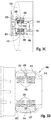
- a longitudinal sealer in another embodiment, includes a housing configured to be installed in a foam-in-bag system, an arm movably coupled to the housing, and a heating element having a leading edge exposed through an exterior surface of the arm.
- a position of the arm with respect to the housing is controllable so that the arm is movable between a first location where the leading edge of the heating element is not in contact with a film in a film path of the foam-in-bag system and a second location where the leading edge of the heating element is in contact with the film in the film path of the foam-in-bag system.
- a longitudinal sealer further includes a temperature sensor configured to generate one or more signals indicative of one or more temperatures of the heating element.
- the temperature sensor includes a first resistance temperature detector located on an exterior surface on the heating element.
- the temperature sensor further includes a second resistance temperature detector embedded within the heating element.
- the longitudinal sealer when the housing is installed in the foam-in-bag system, the longitudinal sealer is configured to be communicatively coupled to a controller of the foam-in-bag system.
- the longitudinal sealer is configured to send the one or more signals generated by the temperature sensor to the controller, and the controller is configured to control a temperature of the heating element based on the one or more signals.
- the controller is configured to control the temperature of the heating element within a range of any one of 1 °C, 2°C, or 5°C of a target temperature.
- the controller is configured to control the position of the arm with respect to the housing.
- the foam-in-bag system includes an actuator configured to engage the longitudinal sealer to move the arm, and the controller is configured to control the position of the arm with respect to the housing by controlling the actuator.
- the actuator is configured to engage a plunger of the longitudinal sealer, and the plunger is configured to contact the arm to cause the arm to rotate in a first rotational direction.
- the housing further includes a biasing element configured to bias the arm in a second rotational direction opposite the first rotational direction, whereby the biasing element biases the arm in the second rotational direction unless the plunger exerts a force on the arm so that a torque on the arm by the plunger overcomes a torque on the arm by the biasing element to cause the arm to rotate in the first rotational direction.
- the housing is configured to be installed in and removed from the foam-in-bag system manually without the use of tools.
- the housing includes a slot configured to be slid into a bracket of the foam-in-bag system.
- the slot includes a bore
- the bracket includes a spring-loaded pin
- the bore is configured to receive a first end of the spring-loaded pin.
- a second end of the spring-loaded pin includes a handle configured to permit a user to grasp the spring-loaded pin and pull the first end of the spring-loaded pin out of the bore.
- Polyurethane foam may be formed by mixing foaming chemical precursors, such as an isocyanate compound with a hydroxyl-containing material, such as a polyol (i.e., a compound that contains multiple hydroxyl groups), typically in the presence of water and a catalyst.
- foaming chemical precursors such as an isocyanate compound
- a hydroxyl-containing material such as a polyol (i.e., a compound that contains multiple hydroxyl groups)
- the water reacts with isocyanate to produce carbon dioxide gas, which acts as a blowing or foaming agent to expand the polyurethane into a foamed cellular structure (i.e., a polyurethane foam).
- the foam precursors may be mixed and dispensed into flexible plastic bags, for example, as the bags are formed from plastic film. As the precursors react to form expanding foam within the bag, the bag may be sealed closed. The bag may then be placed into a box holding an object to be cushioned. The foam tends to expand within the bag into the available space inside the box to form a custom foam cushions around the packaged object.
- Machines for producing foam-in-bag cushions are described, for example, in U.S. Pat. Nos.
- Machines that produce foam-in-bag packaging may use a dispenser in which foam precursors enter the dispenser to mix with one another in an internal mixing chamber of the dispenser to form a foamable composition.
- the resultant foamable composition then exits the dispenser via a discharge outlet. See for example, U.S. Pat. Nos. 4,898,327 and 5,255,847 , each of which is incorporated herein in its entirety by reference.
- foam-in-bag systems include sources of chemical precursors. When mixed, these chemical precursors react to form foam that expands to fill a volume that is many times greater (e.g., hundreds of times greater) than the volume of the chemical precursors themselves.
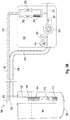
- FIG. 1A Depicted in Fig. 1A is an embodiment of a foam-in-bag system 100 with a first source 102 A of a first chemical precursor 104 A and a second source 102 B of a second chemical precursor 104 B .
- the figures herein show multiple instances of an item using the same reference number and a different subscript to differentiate the individual instances (e.g., the first source 102 A and the second source 102 B ), the items collectively will be referred to herein using only the reference number (e.g., the first and second sources 102).
- the first and second sources 102 hold the first and second chemical precursors 104 separately and allow the foam-in-bag system 100 to draw the first and second chemical precursors 104 for dispensing into a formed bag.
- the first and second sources 102 are drums, barrels, tanks, vats, bottles, or other containers that are capable of holding the chemical precursors.
- the first and second sources 102 are in the form of metal drums.
- Each of the first and second sources 102 holds an amount of the first and second chemical precursors 104, respectively, and allows the foam-in-bag system 100 to draw out the first and second chemical precursors 104 over time as the foam-in-bag system 100 forms bags and dispenses small amounts of the first and second chemical precursors 104 into each bag.
- a schematic diagram of a pumping system 106 for providing the first and second chemical precursors 104 to the foam-in-bag system 100 is shown in Fig. 1B .
- the pumping system 106 includes a first dip tube system 108 A capable of drawing the first chemical precursor 104 A out of the first source 102 A and a second dip tube system 108 B capable of drawing the second chemical precursor 104 B out of the second source 102 B .
- the first and second dip tube systems 108 have a weight that allows a user to lift each of the first and second dip tube systems 108 out of the first and second sources 102 manually and replace the first and second dip tube systems 108 into different sources of chemical precursors manually without the use of tools.
- the first dip tube system 108 A includes a dip tube 109 A through which a feed line 110 A passes.
- the feed line 110 A is usable to draw the first chemical precursor 104 A out of the first source 102 A .
- the first dip tube system 108 A also includes a dip tube 111 A through which a return line 112 A passes.
- the return line 112 A is usable for priming and/or pressure bleeding the feed line 110 A .
- the dip tubes 109 A and 111 A are coupled to a manifold 113 A that is configured to remain outside of the source 102 A .
- the second dip tube system 108 B includes a dip tube 109 B through which a feed line 110 B passes.
- the feed line 110 B is usable to draw the second chemical precursor 104 B out of the second source 102 B .
- the first dip tube system 108 B also includes a dip tube 111 B through which a return line 112 B passes.
- the return line 112 B is usable for priming and/or pressure bleeding the feed line 110 B .
- the dip tubes 109 B and 111 B are coupled to a manifold 113 B that is configured to remain outside of the source 102 B .
- the dip tubes 109 A and 111 A are separate dip tubes and the dip tubes 109 B and 111 B are separate dip tubes.
- the dip tubes 109 A and 111 A can be a single dip tube through which both of the feed line 110 A and the return line 112 A pass and the dip tubes 109 B and 111 B can be a single dip tube through which both of the feed line 110 B and the return line 112 B pass.
- the feed line 110 A includes filters 114 A to filter the first chemical precursor 104 A passing through the feed line 110 A and a check valve 116 A configured to permit the first chemical precursor 104 A to pass only in one direction.
- the feed line 110 B includes filters 114 B to filter the second chemical precursor 104 B passing through the feed line 110 B and a check valve 116 B configured to permit the second chemical precursor 104 B to pass only in one direction.
- the check valves 116 are umbrella style one-way valves configured to prevent residual chemical from flowing back out when the dip tube systems 108 are changed from an empty container to a full container.
- the filters 114 upstream of the check valves 116 are coarse filters configured to prevent large debris from reaching the check valves 116 and the filters 114 downstream of the check valves 116 are fine filters configured to prevent small debris from passing through the feed lines 110 with the chemical precursors 104.
- the filters 114 upstream of the check valves 116 are coarse filters configured to prevent large debris from reaching the check valves 116 and the filters 114 downstream of the check valves 116 are fine filters configured to prevent small debris from passing through the feed lines 110 with the chemical precursors 104.
- the pumping system 106 also includes a first transfer pump system 118 A and a second transfer pump system 118 B .
- a hose 120 A passes between the manifold 113 A of the first dip tube system 108 A and the first transfer pump system 118 A .
- the feed line 110 A passes through the hose 120 A between the manifold 113 A and the first transfer pump system 118 A .
- a hose 121 A passes between the manifold 113 A of the first dip tube system 108 A and the first transfer pump system 118 A .
- the return line 112 A passes through the hose 121 A between the manifold 113 A and the first transfer pump system 118 A .
- a hose 120 B passes between the manifold 113 B of the second dip tube system 108 B and the second transfer pump system 118 B .
- the feed line 110 B passes through the hose 120 B between the manifold 113 B and the second transfer pump system 118 B .
- a hose 121 B passes between the manifold 113 B of the first dip tube system 108 B and the second transfer pump system 118 B .
- the return line 112 B passes through the hose 121 B between the manifold 113 B and the second transfer pump system 118 B .
- the transfer pump systems 118 are located in a housing that is external to the sources 102 and external to the foam-in-bag system 100.
- the transfer pump systems 118 can be located in the sources 102 or located in the foam-in-bag system 100. While the embodiment depicted in Fig. 1B shows the hoses 120 and 121 being separate hoses, it will be apparent that other embodiments may include a single hose that carries both the feed line 110 A and the return line 112 A between the manifold 113 A and the first transfer pump system 118 A and a single hose that carries both the feed line 110 B and the return line 112 B between the manifold 113 B and the second transfer pump system 118 B .
- the feed lines 110, the return lines 112, and/or the hoses 120 and 121 may be transparent or semi-transparent, which allows an outside observer to see whether chemical precursors 104 are passing through the feed lines 110 and/or the return lines 112 or whether there is any gas (e.g., an air bubble) in the feed lines 110 and/or the return lines 112.
- the feed lines 110, the return lines 112, and/or the hoses 120 and 121 may not be transparent or semi-transparent.
- the first transfer pump system 118 A includes a transfer pump 122 A on the feed line 110 A and the second transfer pump system 118 B includes a transfer pump 122 B on the feed line 110 B .
- the transfer pumps 122 may be any type of pump that is capable of drawing the chemical precursors 104 out of the sources 102.
- the transfer pumps 122 are magnetically coupled gerotor pumps.
- a gerotor pump is a positive displacement pump that uses inner and outer rotors with offset axes that cause dynamically-changing inner volumes to drawn in fluid and push out fluid.
- the magnetic couplings allow these gerotor pumps to locate and operate while minimizing or eliminating seal failures and resultant chemical leakage anywhere outside of the sources 102.
- the gerotor pumps are configured to have an operational throughput of 1.1 cubic centimeters per revolution (cc/rev), although the transfer pumps 122 may be expected to operate at a lower throughput during normal operation due to operating conditions (e.g., back pressure in the feed lines 110, differing viscosities of the chemical precursors 104).
- the transfer pumps 122 include one more of a piston pump, a diaphragm pump, a screw pump, a gear pump, an hydraulic pump, a peristaltic pump, or any other type of pump.
- the first transfer pump system 118 A includes a check valve 124 A downstream from the transfer pump 122 A on the feed line 110 A and the second transfer pump system 118 B includes a check valve 124 B downstream from the transfer pump 122 B on the feed line 110 B .
- the check valves 124 are mounted to the outlets of the transfer pumps 122.
- the check valves 124 permit flow of the chemical precursors 104 substantially in only one direction in the feed lines 110 (e.g., the downstream direction).
- the check valves 124 also maintains the pressure in the feed lines 110 upstream of the check valves 124 without the need for the transfer pumps 122 to idle merely to maintain pressure in the feed lines 110.
- the check valves 124 are steel ball and seat check valves configured to prevent backflow during idle to reduce wear on the transfer pumps 122.
- One drawback with the use of gerotor pumps is that fluid can bleed upstream through the gerotor gears when the gerotor pump is idling. Avoiding the need for the transfer pumps 122 to idle will eliminate this drawback.
- the first transfer pump system 118 A includes a pressure transducer 126 A and a temperature sensor 128 A upstream from the transfer pump 122 A on the feed line 110 A .
- the second transfer pump system 118 B includes a pressure transducer 126 B and a temperature sensor 128 B upstream from the transfer pump 122 B on the feed line 110 B .
- the pressure transducers 126 are configured to provide an indication of the pressure in the feed lines 110 upstream of the check valves 124. In some embodiments, the pressure transducers 126 are configured to detect pressure within a range between -15 psi and +5 psi.
- the temperature sensors 128 are configured to provide an indication of the temperature of the chemical precursor 104 in the feed lines 110 upstream of the check valves 124.
- the first transfer pump system 118 A includes a bleed valve 130 A and a prime valve 132 A arranged in parallel on the return line 112 A , with a filter 134 A located on the parallel line with the bleed valve 130 A .
- the second transfer pump system 118 B includes a bleed valve 130 B and a prime valve 132 B arranged in parallel on the return line 112 B , with a filter 134 B located on the parallel line with the bleed valve 130 B .
- the bleed valves 130 have relatively small openings and the filters 134 decrease the likelihood of debris in the chemical precursor clogging the bleed valves 130.
- the bleed valves 130 and prime valves 132 can be selectively and independently opened and closed to allow the chemical precursors 104 to flow through the return lines 112 such that the chemical precursors 104 are withdrawn from the feed lines 110 at points that are downstream of the check valves 124 and returned to the sources 102.
- the bleed valves 130 and prime valves 132 can also be selectively and independently opened and closed to prevent flow of the chemical precursors 104 through the return lines 112. Examples of when the bleed valves 130 and prime valves 132 may be opened or closed are discussed below.
- the bleed valves 130 have a higher pressure rating than the prime valves 132.
- the bleed valves 130 are rated to 850 psi (5.86 MPa) and the prime valves 132 are rated to 50 psi (345 kPa). In some embodiments, the bleed valves 130 are configured to be open when they are unpowered and the prime valves 132 are configured to be closed when they are unpowered.
- the pumping system 106 also includes a first metering pump system 136 A and a second metering pump system 136 B .
- the metering pump systems 136 are located in the base of the foam-in-bag system 100. In other embodiments, the metering pump systems 136 can be located elsewhere the foam-in-bag system 100 or external to the foam-in-bag system 100.
- a hose 138 A passes between the first transfer pump system 118 A and the first metering pump system 136 A and a hose 138 B passes between the second transfer pump system 118 B and the second metering pump system 136 B .
- the portions of the feed lines 110 are located in the hoses 138.
- the hoses 138 may be a variety of different lengths, such as anywhere from 1 foot (0.3 meters) to 100 feet (30 meters) or greater than 100 feet (30 meters). Because the hoses 138 to be a variety of different lengths, the sources 102 can be placed at a number of different locations with respect to the foam-in-bag system 100 and the length of the hoses 138 can be selected so that the hoses 138 are an appropriate length for the distance between the sources 102 and the foam-in-bag system 100. In some embodiments, as the lengths of the hoses 138 are increased, the inner diameters of the feed lines 110 may be increased to minimize pressure drop over the longer length of the feed lines 110.
- the first metering pump system 136 A includes a metering pump 140 A on the feed line 110 A and the second metering pump system 136 B includes a metering pump 140 B on the feed line 110 B .
- the transfer pumps 122 may be any type of pump that is capable of pumping the chemical precursors 104 through the feed lines 110.
- the metering pumps 140 are magnetically coupled gerotor pumps.
- the gerotor pumps are configured to have an operational throughput of 1.1 cc/rev, and the metering pumps 140 may be expected to operate at or near that operational throughput during normal operation (e.g., such as under the condition where the inlet pressure and the outlet pressure of the metering pumps 140 are the same or close to each other).
- the metering pumps 140 include one more of a piston pump, a diaphragm pump, a screw pump, a gear pump, an hydraulic pump, a peristaltic pump, or any other type of pump.
- the first metering pump system 136 A includes an input pressure transducer 142 A and an outlet pressure transducer 144 A .
- the input pressure transducers 142 are located upstream of the metering pumps 140 on the feed lines 110 and the outlet pressure transducers 144 are located downstream of the metering pumps 140.
- the input pressure transducers 142 are coupled to an input of the metering pumps 140 and the outlet pressure transducers 144 are coupled to an output of the metering pumps 140.
- the input and output pressure transducers 142 and 144 are configured to detect pressure within a range between 0 psi and 1000 psi.
- the operation of the metering pumps 140 are controlled in order to minimize the pressure differential between the pressure at the input pressure transducers 142 and the pressure at the outlet pressure transducers 144.
- the operation of the metering pump 140 A is controlled in order to minimize the pressure differential between the pressure at the input pressure transducer 142 A and the pressure at the outlet pressure transducer 144 A .
- the operation of the metering pump 140 B is controlled in order to minimize the pressure differential between the pressure at the input pressure transducer 142 B and the pressure at the outlet pressure transducer 144 B .
- the pumping system 106 also includes a first dispenser manifold 146 A and a second dispenser manifold 146 B .
- a hose 148 A passes between the first metering pump system 136 A and the first dispenser manifold 146 A and a hose 148 B passes between the second metering pump system 136 B and the second dispenser manifold 146 B .
- the hose 148 A includes a heating element 150 A , a temperature sensor 152 A , and a thermal protector 154 A .
- the hose 148 B includes a heating element 150 B and a thermal protector 154 B .
- the heating elements 150 are configured to be in direct contact with and heat the chemical precursor 104 in the feed line 110.
- each of the heating elements 150 is a heater wire that is directly in contact with the chemical precursors 104 in the feed lines 110.
- the heater wire is rated to 25 ohms, line voltage (e.g., 208 VAC), and/or 1750 watts.
- the thermal protectors 154 are configured to generate a signal indicative of an overheating condition, which may be used to stop operation of some or all of the pumping system 106.
- the first dispenser manifold 146 A includes an input temperature sensor 156 A configured to be in contact with and determine a temperature of the first chemical precursor 104 A as it is received in the first dispenser manifold 146 A from the hose 148 A .
- the first dispenser manifold 146 A also includes an input block 158 A (e.g., an aluminum block) through which the feed line 110 A passes.
- the input block 158 A includes a heating element 160 A configured to heat the input block 158 A , a temperature sensor 162 A configured to determine a temperature of the input block 158 A , and a thermal protector 164 A configured to generate a signal indicative of an overheating condition of the input block 158 A .
- the first dispenser manifold 146 A also includes a filter 166 A configured to filter the first chemical precursor 104 A in the portion of the feed line 110 A that passes through the input block 158 A .
- the first dispenser manifold 146 A also includes an output block 168 A (e.g., an aluminum block) through which the feed line 110 A passes.
- the output block 168 A includes a heating element 170 A configured to heat the output block 168 A and a temperature sensor 172 A configured to determine a temperature of the input block 168 A . Signals generated by any or all of the temperature sensors 156 A , 162 A , and 172 A may be used to control operation of one or both of the heating elements 160 A and 170 A .
- the second dispenser manifold 146 B includes an input temperature sensor 156 B configured to be in contact with and determine a temperature of the second chemical precursor 104 B as it is received in the second dispenser manifold 146 B from the hose 148 B .
- the second dispenser manifold 146 B also includes an input block 158 B (e.g., an aluminum block) through which the feed line 110 B passes.
- the input block 158 B includes a heating element 160 B configured to heat the input block 158 B , a temperature sensor 162 B configured to determine a temperature of the input block 158 B , and a thermal protector 164 B configured to generate a signal indicative of an overheating condition of the input block 158 B .
- the second dispenser manifold 146 B also includes a filter 166 B configured to filter the second chemical precursor 104 B in the portion of the feed line 110 B that passes through the input block 158 B .
- the second dispenser manifold 146 B also includes an output block 168 B (e.g., an aluminum block) through which the feed line 110 B passes.
- the output block 168 B includes a heating element 170 B configured to heat the output block 168 B and a temperature sensor 172 B configured to determine a temperature of the input block 168 B . Signals generated by any or all of the temperature sensors 156 B , 162 B , and 172 B may be used to control operation of one or both of the heating elements 160 B and 170 B .
- the heating elements 160 are configured to heat the input blocks 158. In some cases, the heating elements 160 are cartridge style heaters that are in direct contact with the input blocks 158 but not in direct contact with the chemical precursors 104 passing through the feed lines 110. In some examples, the heating elements 160 are cartridge style heaters rated to 500 watts. In some embodiments, the heating elements 170 are configured to heat the output blocks 168. In some cases, the heating elements 170 are cartridge style heaters that are in direct contact with the output blocks 168 but not in direct contact with the chemical precursors 104 passing through the feed lines 110. In some examples, the heating elements 170 are cartridge style heaters rated to 150 watts.
- the feed lines 110 pass from the dispenser manifolds 146 into a dispenser 174.
- the dispenser 174 includes a mixing cartridge manifold 176 that dispenses the first and second chemical precursors 104 A and 104 B into formed bags.
- the mixing cartridge manifold 176 includes a mixing cartridge 178 configured to be selectively controlled to dispense specific amounts of the first and second chemical precursors 104 A and 104 B into formed bags.
- the mixing cartridge 178 is driven by a motor (e.g., a servo motor) to provide control of the ratio of dispensing of the first chemical precursor 104 A and the second chemical precursor 104 B . This also allows the motor controls to be closely synchronized with the opening and closing of the mixing cartridge 178.
- the mixing cartridge manifold 176 includes a heating element 180 configured to heat the mixing cartridge manifold 176 and a temperature sensor 182 configured to determine a temperature of the mixing cartridge manifold 176. Signals generated the temperature sensor 182 may be used to control operation of the heating element 180.
- the heating element 180 is configured to heat the mixing cartridge manifold 176.
- the heating element 180 is a cartridge style heater that is in direct contact with the mixing cartridge manifold 176 but not in direct contact with the chemical precursors 104.
- the heating element 180 is a cartridge style heater rated to 80 watts.
- the mixing cartridge 178 has relatively small orifices to control the amount of the chemical precursors 104 being dispensed. In order to avoid clogging the mixing cartridge 178, the filters 166 in the dispenser manifolds 146 can be fine filters to filter out small debris in the feed lines 110 before the chemical precursors 104 reach the mixing cartridge 178.
- the dispenser 174 also includes a manual shutoff valve 184 A on the feed line 110 A before the first chemical precursor 104 A reaches the mixing cartridge manifold 176 and a manual shutoff valve 184 B on the feed line 110 B before the second chemical precursor 104 B reaches the mixing cartridge manifold 176.
- the manual shutoff valves 184 can be closed manually by a user before the mixing cartridge manifold 176 and/or the mixing cartridge 178 is removed, such as for replacement of the mixing cartridge manifold 176 and/or the mixing cartridge 178 or cleaning of the mixing cartridge manifold 176 and/or the mixing cartridge 178.
- the ability to manually close the manual shutoff valves 184 allows a user to ensure that the chemical precursors 104 do not leak when the mixing cartridge manifold 176 and/or the mixing cartridge 178 is removed.
- the manual shutoff valves 184 are ball valves.
- the foam-in-bag system 100 will form bags, dispense chemical precursors into each formed bag, and then seal the bag after the chemical precursors have been dispensed. The chemical precursors then foam up inside the sealed bag.
- the mixing cartridge 178 will dispense the chemical precursors intermittently.
- the mixing cartridge 178 dispenses an amount of the chemical precursors (also called a "shot" of the chemical precursors) into each bag.
- the foam-in-bag system 100 requires time to seal the bag into which the shot has been dispensed and time to form the next bag before the next shot of chemical precursors is dispensed by the mixing cartridge 178.
- components of the pumping system 106 are controlled to cause the chemical precursors 104 to flow at specific flow rates in the feed lines 110 and/or to cause specific amounts of chemical precursors 104 to be dispensed by the mixing cartridge 178.
- the metering pumps 140 are driven at a target speed (e.g., a target rotation per minute), determined by a desired flow rate of the chemical precursors 104 and a desired ratio of the chemical precursors 104.
- the metering pumps 140 are accelerated to a set speed in as short a time as is feasible and then held at the set speed for a time of the duration of the shot as precisely as feasible.
- the transfer pumps 122 are also driven in order to minimize or eliminate the pressure differential between the input and output of the metering pumps 140.
- the speed of the transfer pumps 122 can be controlled to minimize or eliminate the difference between the signals generated by the respective set of input pressure transducers 142 and the outlet pressure transducers 144. Under many conditions, this control of the transfer pumps 122 will cause the speed of the transfer pumps 122 to be higher than the speed of the metering pumps 140.
- the depicted embodiment of the pumping system 106 includes four pumps: the two transfer pumps 122 and the two metering pumps 140. While it is possible to pump the first and second chemical precursors from the sources 102 to the dispenser 174 using two pumps only (i.e., one pump for the first chemical precursor 104 A and one pump for the second chemical precursor 104 B ), the four-pump pumping system 106 provide increased precision and control of flow rate of the chemical precursors 104 and the timing of the flow of the chemical precursors 104. In some embodiments, it is desirable for the chemical precursors 104 to begin flowing out of the dispenser as soon as possible after the mixing cartridge 178 is opened. This may require a high rate of acceleration by the pumping system.
- metering pumps 140 to meet the acceleration demands of the dispenser and the transfer pumps 122 to provide appropriate flow rates out of the sources 102 make this high rate of acceleration possible.
- the transfer pumps 122 and the metering pumps 140 are servo motors (e.g., gerotors) in order to meet the speed and control demands of the pumping system 106.
- the bleed valves 130 and the prime valves 132 in the transfer pump systems 118 can be selectively and independently opened and closed to allow the chemical precursors 104 to flow through the return lines 112 such that the chemical precursors 104 are withdrawn from the feed lines 110 at points that are downstream of the check valves 124 and returned to the sources 102.
- the bleed valves 130 can be opened to allow chemical precursors 104 to pass from the feed lines 110 into the return lines 112. This may be used to prevent pressure build up in the return lines 112 downstream of the check valves 124.
- the bleed valves 130 is opened (either manually or automatically) to control the pressure within a predetermined pressure range at or near a pressure that is in the feed lines 110 downstream of the transfer pumps 122.
- the pressure in the feed lines increases due to thermal expansion when the chemical precursors 104 are heated in the feed lines 110.
- the prime valves 132 can be opened to allow chemical precursors 104 and/or gas (e.g., air) to pass from the feed lines 110 into the return lines 112. This may be helpful when priming the pumping system 106 after the dip tube systems 108 are changed from one container (e.g., an empty drum) to another container (e.g., a full drum).
- the transfer pumps 122 can be drum pumps.
- the prime valves 132 and their associated controls may be omitted from the pumping system 106.
- a bleed valves 130 may still be used. If the bleed valves 130 were located on the manifolds of the transfer pump systems 118, then the return lines 112 may be omitted from the pumping system 106.
- the pumping system 106 has a number of benefits.
- the pumping system 106 provides reliable control of flow rates and ratios of the chemical precursors 104 when dispensing any type of shots.
- the control of the ratios and flow rates of the chemical precursors 104 allows for the resultant foam to have substantially the same quality under a variety of conditions of the shots being dispensed. For example, the foam quality at the very beginning of a shot will be the same as it is at the end of the shot. In another example, there is no lead or lag on the pressure or flow of the chemical precursors 104. In another example, when flow rates of the chemical precursors 104 are well regulated, the amount of the chemical precursors 104 dispensed into bags and the amount of the resultant foam in the bags is better controlled.
- the dip tube systems 108 can be simply removed from one source (e.g., drum) when the source is empty and inserted into another source that is full without the need for extensive manual work by a user because the pumping system 106 can automatically prime the dip tube systems 108 after they are inserted into new containers.
- one source e.g., drum
- the controls in the pumping system 106 can result in cost savings for an operator of the foam-in-bag system 100. For example, when an improper ratio of the first and second chemical precursors 104 A and 104 B are dispensed into a bag, some amount of one of the first and second chemical precursors 104 A and 104 B will not react in the bag. This results in the unused amounts of the chemical precursors 104 that add cost to each bag without adding any value.
- the use of two pumps on each of the feed lines 110 i.e., one of the transfer pumps 122 and one of the metering pumps 140 reduces the overall wear that would be incurred if only one pump was used on the each of the feed lines 110.
- This reduced wear is especially the case if one or both of the chemical precursors 104 is a non-lubricating chemical precursor.
- Reduced wear on the pumps means fewer maintenance needs, less downtime for maintenance, lower maintenance costs, greater metering accuracy by the pumps, longer peak efficiency of the pumping system 106, and more efficient use of the chemical precursors 104 by the pumping system 106.
- the transfer pumps 122 are expected to operate at a higher rate (e.g., higher revolutions per minute (RPM)) than the metering pumps 140.
- RPM revolutions per minute
- the transfer pumps 122 are new, they are more efficient, and will run at a lower rate.
- the transfer pumps 122 starts to wear, they will turn at higher rates to keep up.
- the condition of the transfer pumps 122 can be monitored by comparing the rates of the transfer pumps 122 with the rates of the metering pumps 140. If the differential in rates of the transfer pumps 122 and the metering pumps 140 exceeds a certain level, a signal may be generated to clean or change the transfer pumps 122.
- Fig. 2A Depicted in Fig. 2A is an embodiment of a dip tube system 200 that can be used as either of the dip tube systems 108 depicted in Figs. 1A and 1B .
- the dip tube system 200 is shown in Fig. 2A having been inserted into a source 202 of chemical precursor 204.
- the dip tube system 200 includes a dip tube 209 configured to be inserted through an opening in the source 202 into the chemical precursor 204 in the source 202.
- the dip tube system 200 also includes a manifold 213 that is coupled to the dip tube 209 and remains outside of the source 202.
- the dip tube system 200 is capable of being used to siphon the chemical precursor 204 out of the source 202.
- a transfer pump system 218 that is coupled to the manifold 213 of the dip tube system 200 via a hose 220.
- the dip tube system 200, the source 202 of the chemical precursor 204, the transfer pump system 218, and the hose 220 are all depicted in a schematic diagram in Fig. 2B .
- the transfer pump system 218 can also be coupled to the manifold 213 of the dip tube system 200 via a hose 221, although the hose 221 is not depicted in Fig. 2A .
- the feed line 210 and the return line 212 pass through the dip tube 209 and the manifold 213 of the dip tube system 200, through the hoses 220 and 221, respectively, and through the transfer pump system 218.
- the feed line 210 includes filters 214 to filter the chemical precursor 204 passing through the feed line 210 and a check valve 216 configured to permit the chemical precursor 204 to pass substantially only in the downstream direction.
- the check valve 216 is an umbrella style one-way valve configured to prevent residual chemical precursor 204 from flowing back out when the dip tube system 200 is changed from an empty container to a full container.
- the filter 214 upstream of the check valve 216 is a coarse filter configured to prevent large debris from reaching the check valves 116 and the filter 214 downstream of the check valve 216 is a fine filter configured to prevent small debris from passing through the feed lines 210 with the chemical precursor 204.
- the transfer pump system 218 includes a transfer pump 222 on the feed line 210.
- the transfer pump 222 may be any type of pump that is capable of drawing the chemical precursor 204 out of the source 202.
- the transfer pump 222 is a gerotor pump.
- the gerotor pump is configured to have an operational throughput of 1.1 cubic centimeters per revolution (cc/rev).
- the transfer pump 222 includes one or more of a piston pump, a diaphragm pump, a screw pump, a gear pump, an hydraulic pump, a peristaltic pump, or any other type of pump.
- the transfer pump system 218 includes a check valve 224 downstream from the transfer pump 222 on the feed line 210.
- the check valve 224 is mounted to the outlet of the transfer pump 222.
- the check valve 224 permits flow of the chemical precursor 204 in substantially only the downstream direction in the feed line 210.
- the check valve 224 also monitor the pressure in the feed line 210 upstream of the check valve 224.
- the check valve 224 is a steel ball and seat check valve configured to prevent backflow during idle to reduce wear on the transfer pump 222.
- the transfer pump system 218 includes a pressure transducer 226 and a temperature sensor 228 upstream from the transfer pump 222 on the feed line 210.
- the pressure transducer 226 is configured to provide an indication of the pressure in the feed line 210 upstream of the check valve 224.
- the pressure transducer 226 is configured to detect pressure within a range between -15 psi and +5 psi.
- the temperature sensor 228 is configured to provide an indication of the temperature of the chemical precursor 204 in the feed line 210 upstream of the check valve 224.
- the transfer pump system 218 includes a bleed valve 230 and a prime valve 232 arranged in parallel on the return line 212, with a filter 234 located on the parallel line with the bleed valve 230.
- the bleed valve 230 has a relatively small opening and the filter 234 decreases the likelihood of debris in the chemical precursor 204 clogging the bleed valve 230.
- the bleed valve 230 and the prime valve 232 can be selectively and independently opened and closed to allow the chemical precursor 204 to flow through the return line 212 such that the chemical precursor 204 is withdrawn from the feed line 210 at a point that is downstream of the check valve 224 and returned to the source 202.
- the bleed valve 230 opens a higher pressure than the prime valve 232.
- the bleed valve 230 is configured to open at 850 psi (5.86 MPa) and the prime valve 232 is configured to open at 50 psi (345 kPa). In some embodiments, the bleed valve 230 is configured to be open when it is unpowered and the prime valve 232 is configured to be closed when it is unpowered.
- the dip tube system 200 with the transfer pump system 218 depicted in Figs. 2A and 2B .
- the use of the parallel bleed and prime valves 230 and 232 on the return line 212 facilitates priming of the dip tube system 200 to clear the feed line 210 of gas (e.g., air).
- gas e.g., air
- the user can merely insert the dip tube system 200 into a source of chemical precursor, and the transfer pump system 218 can prime the dip tube system 200 automatically without any further user work.
- the use of the parallel bleed and prime valves 230 and 232 on the return line 212 facilitates pressure relief within the feed line 210 during idle, which improve foam quality and consistency when a shot of the chemical precursor 204 is dispensed with another chemical precursor.
- the bleed valve 230 when the bleed valve 230 is configured to be open when it is unpowered, the bleed valve 230 will open when the transfer pump system 218 is turned off to automatically bring the pressure in the feed line 210 to zero when the transfer pump system 218 is turned off. Having zero pressure in the feed line 210 when the transfer pump system 218 is turned off enhances safety of the system.
- the dip tube system 200 depicted in Figs. 2A and 2B is the ability to place the filters 214 inside the portion of the feed line 210 in the dip tube 209.
- one or more of the filters 214 is a long, fine mesh screen filter attached to the inside diameter of the feed line 210. This arrangement allows for the filter to have a very large surface area.
- the filters 214 can be located along a majority of the length of the dip tube 209. This may allow for the filters 114 to be large enough to be usable for the entire expected life of the dip tube system 200 without any maintenance. The ability to avoid maintenance of the filters 214 can be extremely beneficial in the case where the chemical precursor 204 is hazardous or otherwise dangerous.
- some types of chemical precursors will form crystals on the surface of the filters 214 if the filters are exposed to air, and the ability to keep the filters 214 substantially submerged in the chemical precursor 204. These crystals are potentially harmful to the feed line 210, a downstream dispenser (e.g., dispenser 174), or other parts of a pumping system (e.g., pumping system 106), and keeping the filters 214 substantially submerged in the chemical precursor 204 deters the formation of these crystals.
- the pressure transducer 226 in the feed line 210 upstream of the transfer pump 222 provides a number of benefits.
- the pressure measurement by the pressure transducer 226 can be used to calculate a liquid level of the chemical precursor 204 in the source 202.
- the calculation of the liquid level can be made when the chemical precursor 204 is not flowing based on principles of hydrostatic pressure in a non-moving fluid using the height of the pressure transducer 226 and the measured pressure in the feed line 210. This alleviates the need for any kind of a liquid level sensor in the source 202 (e.g., a float inside the source 202, an optical sensor in the source 202, etc.).
- a controller (not shown), such as a computing device, communicatively coupled to the pressure transducer can calculate the liquid level of the chemical precursor 204 in the source 202 automatically.
- the controller can issue one or more signals to a user when the calculated liquid level reaches particular levels so the user knows to order a new source of the chemical precursor 204 when the liquid level reaches a low level, to replace the source 202 with a new source when the liquid level reaches an empty level, or to perform any other action based on the calculated liquid level.
- the source 202 does not need to be transparent or semi-transparent for the user to know how much of the chemical precursor 204 remains in the source 202.
- the pressure measurement by the pressure transducer 226 can be used to detect clogs in the feed line 210 upstream of the transfer pump 222. If the feed line 210 becomes clogged anywhere between the bottom of the dip tube 209 and the pressure transducer 226, the flow of the chemical precursor 104 through the feed line 210 would cease and the pressure between the blockage and the transfer pump 222 would decrease. The pressure transducer 226 would detect the low pressure and, in response, could issue a signal. This signal would alert a user to the blockage much sooner than would otherwise be detected and would avoid waste of other chemical precursors that would otherwise be dispensed until the blockage was detected. Another benefit of the pressure measurement by the pressure transducer 226 is the ability to avoid crossovers, which can destroy a foam-in-bag system.
- the pressure measurement by the pressure transducer 226 can be used to detect cavitation in the feed line 210. If the chemical precursor 204 is in liquid form, the chemical precursor 204 has a specific vapor pressure at a given temperature so that the vapor pressure is a function of temperature. Whenever a liquid pressure falls below its vapor pressure, the liquid begins to boil. Cavitation occurs when the drop below the vapor pressure is caused by suction from a pump, and cavitation can cause many problems within the feed line 210 and throughout the pumping system. In some embodiments, if the pressure transducer 226 detects a drop in pressure that approaches a cavitation pressure, the pumping system can shut down and/or provide a warning to the user that cavitation may be possible.
- the temperature sensor 228 is also capable of detecting the temperature within the feed line 210 upstream of the transfer pump 222.
- the temperature in the chemical precursor 204 can be used in addition to the pressure measured by the pressure transducer 226 to ensure accuracy of the determination that conditions are approaching cavitation.
- foam-in-bag systems are capable of forming a bag from a film web, dispensing chemical precursors into the formed bag, and then closing the bag before the chemical precursors fully react an expand to their full volume.
- the film web is provided on a roll where the film is folded in half longitudinally when it is on the roll.
- the foam-in-bag system feeds the film such that the fold in the film becomes one of the longitudinal sides.
- the foam-in-bag system also seals the longitudinal edges of the film opposite the fold to form the other longitudinal side of the bag.
- the ply of film on one side of the fold forms the front of the bag and the ply of film on the other side of the fold forms the back of the bag.
- the foam-in-bag system forms transverse seals in the film to form the bottom and the top of the bag and cuts the film outside of the bottom and the top to separate the bag from the film web.
- Examples of the above-described foam-in-bag systems and a variety of other foam-in-bag systems are provided in U.S. Patent Nos. 4,854,109 ; 4,938,007 ; 5,139,151 ; 5,376,219 ; 5,575,435 ; 5,679,208 ; 5,727,370 ; 6,131,375 ; 6,178,725 ; and 6,472,638 ; the contents of all of which are hereby incorporated by reference in their entirety.
- Film webs for use in foam-in-bag systems are typically provided in are typically supplied on a roll of film.
- the roll typically includes a cylindrical core (e.g., a core made of a paper-based material) with the film web wound around the cylindrical core.
- the core of the roll is typically mounted on a spindle or other structure where the core is able to rotate as the film web is unrolled by the foam-in-bag system.
- the core is removed from the foam-in-bag system and discarded, and a new roll of film is loaded onto the foam-in-bag system. Because the core is merely discarded after use, it is advantageous for the core to be as inexpensive as possible to reduce the overall costs associated with the film.
- One difficulty with the usability of foam-in-bag systems is the time and effort needed to load a roll of film on the foam-in-bag system for the foam-in-bag system to be able to use the film.
- the roll can have a weight that makes it cumbersome or dangerous for one person to handle.
- This difficulty in handling may result in rolls of film falling or otherwise being damaged in a way that deforms the core.
- This problem is exacerbated when cores are made from cheaper materials (e.g., an in effort to reduce the cost of the core), which are more easily deformed.
- a deformed core refers to a core that is not perfectly cylindrical, and includes dented cores, crushed cores, twisted cores, or any other form of a core that is not perfectly cylindrical.
- the core is deformed, it can be difficult for a user to slide the roll over the spindle or other support structure that holds the roll.
- rolls of film may have different widths depending on the size of bags that are intended to be made with the film, and it can be difficult for a user to adjust the spindle or other support structure on the foam-in-bag system to accommodate the different size width while trying to handle a full roll of film.
- This adjustment of the spindle or other support structure typically requires the use of tools (e.g., screwdrivers, ratchets, etc.) that make the adjustment even more difficult for the user.
- a roll 400 of film web on the foam-in-bag system 100 is depicted in Fig. 3A .
- the roll 400 has been placed on a spindle system 402.
- the roll 400 has been shown in Fig. 3A as transparent so that the spindle system 402 is visible; however, in many embodiments, the roll 400 is not transparent.
- the spindle system 402 includes a rod 404.
- the rod 404 is fixedly coupled to a housing 194 of the foam-in-bag system 100 such that the rod 404 does not rotate or translate with respect to the housing 194.
- the rod 404 is cantilevered out from the housing 194 with a proximal end of the rod 404 located near the housing 194 and a distal end of the rod 404 located away from the housing 194.
- the rod 404 is cylindrical in shape with an outer diameter that is less than the inner diameter of the core of the roll 400.
- the spindle system 402 includes a proximal wing 406 and a distal wing 408 that are configured to contact the inner diameter of the core of the roll 400.
- Each of the proximal wing 406 and the distal wing 408 is rotatably coupled to the rod 404.
- each of the proximal wing 406 and the distal wing 408 may have a bore through which the rod 404 passes that permits the each of the proximal wing 406 and the distal wing 408 to rotate around the rod 404.
- the proximal wing 406 is operatively coupled to a motor (not shown) inside of the housing 194 and the motor is capable of selectively rotating the proximal wing 406 around the rod 404.
- the distal wing 408 is not coupled to the motor so that the distal wing 408 is capable of rotating around the rod 404 independently of the operation of the motor.
- the proximal wing 406 and the distal wing 408 are configured to contact the inner diameter of the core of the roll 400 at diametrically-opposed locations on the inner surface of the core.
- the proximal wing 406 includes contact surfaces 410 and the distal wing 408 includes contact surfaces 412.
- the contact surfaces 410 and 410 are spaced away from the rod 404 such that the contact surfaces 410 contact diametrically-opposed locations on the inner surface of the core at the proximal side of the roll 400 and the contact surfaces 412 contact diametrically-opposed locations on the inner surface of the core at the distal side of the roll 400.
- the contact surfaces 410 and 410 are contoured surfaces based on an expected contour of the inner surface of the core of the roll 400. Having contoured surfaces may increase the percentage of the surface area of the contact surfaces 410 and 410 that is in contact with the core of the roll 400.
- the proximal wing 406 also includes non-contact surfaces 414 and the distal wing 408 includes non-contact surfaces 416.
- the non-contact surfaces 414 span between the contact surfaces 410 and the non-contact surfaces 416 span between the contact surfaces 412.
- the non-contact surfaces 414 and 416 do not contact the core of the roll 400.
- the cores in rolls of film can be damaged and deformed during shipping or handling.
- the roll 400 can be positioned with respect to the proximal wing 406 such that any deformities in the proximal end of the roll 400 at the proximal wing 406 are not contacted by the contact surfaces 410 of the proximal wing 406.
- the non-contact surfaces 414 accommodate deformities in the proximal end of the core of the roll 400 while the proximal wing 406 still contacts the core at the contact surfaces 410.
- the roll 400 can be positioned with respect to the distal wing 408 such that any deformities in the distal end of the roll 400 at the distal wing 408 are not contacted by the contact surfaces 412 of the distal wing 408.
- the non-contact surfaces 416 accommodate deformities in the distal end of the core of the roll 400 while the distal wing 408 still contacts the core at the contact surfaces 412.
- the proximal wing 406 is operatively coupled to a motor that controls the rotational position of the proximal wing 406 with respect to the rod 404 and the distal wing 408 is capable of rotating freely on the rod 404.
- the roll 400 is slid over the rod 404 from the distal end of the rod 404 to the proximal end of the rod 404. As the roll 400 is slid over the rod 404, the roll 400 is rotated so that any deformities on the proximal side of the roll 400 are not aligned with the contact surfaces 410 of the proximal wing 406.
- the distal wing 408 is also rotated so that any deformities on the distal side of the roll 400 are not aligned with the contact surfaces 412 of the distal wing 408. In this way, the proximal wing 406 and the distal wing 408 are able to hold the roll 400 despite any deformities in the core of the roll 400. It will be understood that the proximal wing 406 and the distal wing 408 are able to hold the roll 400 regardless of whether the proximal wing 406 and the distal wing 408 are aligned with each other.
- the non-contact surfaces 414 of the proximal wing 406 either be parallel or non-parallel to the non-contact surfaces 416 of the distal wing 408 for the spindle system 402 to support the roll 400.
- An example of the spindle system 402 with the proximal wing 406 and the distal wing 408 not aligned with each other is depicted in Fig. 3B .
- the foam-in-bag system 100 is configured to actively unwind the film from the roll 400.
- active unwinding refers to forced and/or controlled rotation of a roll of film to cause the film to be unwound from the roll
- passive unwinding refers to a roll rotating in response to the film being pulled and/or withdrawn from the roll.
- the roll 400 When the roll 400 is on the proximal wing 406 and the distal wing 408, core of the roll 400 is arranged with respect to the contact surfaces 410 and 412 so that rotation of the roll 400 causes rotation of the proximal wing 406 and the distal wing 408 about the rod 404 and rotation of the proximal wing 406 and the distal wing 408 about the rod 404 causes rotation of the roll 400.
- the proximal wing 406 is operatively coupled to a motor in the housing
- operation of the motor drives rotation of the proximal wing 406 about the rod 404, which causes rotation of the roll 400.
- the rotation of the roll 400 then causes rotation of the distal wing 408 about the rod 404.
- the foam-in-bag system 100 is able to actively unwind film from the roll 400 by driving and/or controlling the motor to rotate the proximal wing 406.
- contact surfaces of wings may include an engagement device to increase the friction between the wing and the core of a roll beyond the fiction from the contact between the contact surfaces and the core.
- the contact surfaces 410 include engagement devices 418. The engagement devices 418 are configured to engage the core of the roll 400 and to decrease the possibility of the core of the roll 400 moving with respect to the contact surfaces 410.
- the engagement devices 418 are biased away from the axis of rotation of the proximal wing 406 into the inner diameter of the core of the roll 400.
- the engagement devices 418 are biased by biasing mechanisms 420 outward away from the axis of rotation of the proximal wing 406.
- the biasing mechanisms 420 are compression springs. In other embodiments, the biasing mechanisms 420 may be any other type of spring or any other mechanisms capable of biasing the engagement devices 418.
- the movement of the engagement devices 418 is restricted by pins 422 in the proximal wing 406, that limit how far outwardly the biasing mechanisms 420 can move the engagement devices 418 away from the axis of rotation and how far inwardly the engagement devices 418 can be forced inwardly toward the axis of rotation.
- the biasing mechanisms 420 are able to force the biasing mechanisms 420 outwardly as far as the pins 422 permit.
- the core of the roll 400 pushes back on the engagement devices 418 so that the engagement devices 418 are in contact with the core and the engagement devices 418 are biased into core by the biasing mechanisms 420.
- the foam-in-bag system 100 is capable of using film rolls of different widths.
- the embodiment of the spindle system 402 depicted in Fig. 3A also includes a number of features for convenience in adjusting the spindle system 402 to accommodate different widths of rolls. These features may also reduce the amount of time and/or labor to remove components of the spindle system 402 for servicing of the foam-in-bag system 100 and/or the spindle system 402.
- the spindle system 402 includes an end cap 424 located on the distal end of the rod 404.
- the end cap 424 is spherical in the depicted embodiment, but could be in the form of a disc, a cube, a rectangular prism, or any other shape.
- the end cap 424 is configured to prevent the distal wing 408 from unintentionally sliding off the distal end of the rod 404.
- the end cap 424 is releasably coupled to the rod 404.
- the rod 404 includes a threaded stud extending axially from the distal end of the rod 404 and the end cap 424 includes a threaded bore that is configured to engage the threaded stud on the distal end of the rod 404.
- the end cap 424 can be removed during servicing of the foam-in-bag system 100 to permit the distal wing 408 and the proximal wing 406 to be removed from the rod 404.
- the spindle system 402 also includes a distal ring clamp 426.
- the distal ring clamp 426 is releasably clampable to the rod 404.
- the distal ring clamp 426 is configured to prevent the distal wing 408 from sliding toward the proximal end of the rod 404.
- the distal ring clamp 426 can be clamped and unclamped without the use of tools. In the instance shown in Fig. 3A , the distal ring clamp 426 is clamped to the rod 404 such that the distal wing 408 is between the end cap 424 and the distal ring clamp 426.
- the distal wing 408 is substantially as far from the proximal wing 406 as the end cap 424 will permit.
- the roll 400 may be not as wide as shown in Fig. 3A .
- the distal wing 408 may need to be closer to the proximal wing 406 for the roll 400 to fit on the distal wing 408 and the proximal wing 406.
- a user may unclamp the distal ring clamp 426, move the distal ring clamp 426 closer to the proximal wing 406, and then clamp the distal ring clamp 426 on the rod 404.
- This repositioning of the distal ring clamp 426 permits the distal wing 408 to move closer to the proximal wing 406 to accommodate a narrower roll of film.
- the distal ring clamp 426 can be unclamped and removed during servicing of the foam-in-bag system 100 to permit the distal wing 408 and the proximal wing 406 to be removed from the rod 404.
- the spindle system 402 also includes a proximal ring clamp 428.
- the proximal ring clamp 428 is releasably clampable to the rod 404.
- the proximal ring clamp 428 is configured to prevent the proximal wing 406 from sliding toward the distal end of the rod 404 and to keep the proximal wing 406 operatively coupled to the motor inside the housing 194.
- the proximal ring clamp 428 can be clamped and unclamped without the use of tools.
- the proximal ring clamp 428 can be unclamped and removed during servicing of the foam-in-bag system 100 to permit the proximal wing 406 to be removed from the rod 404.
- a roll guide 430 Coupled to the proximal ring clamp 428 is a roll guide 430.
- the roll guide 430 is located around the rod 404.
- the roll guide 430 is conical with the distal end of the roll guide 430 having a diameter that is less than a diameter of the proximal end of the roll guide 430.
- the depicted embodiment of the proximal wing 406 includes engagement devices 418 on the contact surfaces 410.
- the engagement devices 418 are configured to engage the inner surface of the core of the roll 400 and to deter rotation of the roll 400 with respect to the proximal wing 406. While the engagement devices 418 may deter relative rotation of the roll 400 and the proximal wing 406, the contact surfaces 410 and 412 and the engagement devices 418 may not sufficiently deter axial translation of the roll 400 toward the distal end of the rod 404.
- one of the contact surfaces 412 of the distal wing 408 includes a releasable clip 432.
- the releasable clip 432 When the roll 400 is loaded on the spindle system 402, the releasable clip 432 is configured to contact the distal end of the roll 400 to deter axial movement of the roll 400 towards the distal end of the rod 404. In some embodiments, the releasable clip 432 is contoured to automatically retract as the roll 400 is loaded on the spindle system 402 and to extend into the position shown in Fig. 3A after the roll 400 is loaded on the spindle system 402.
- the foam-in-bag system 100 can accommodate different widths of the roll 400. Examples of different widths of the roll 400 on the foam-in-bag system 100 are shown in Figs. 4A to 4D . More specifically, Figs. 4A and 4B depict front and rear perspective views, respectively, of the foam-in-bag system 100 arranged to accommodate a wide roll and Figs. 4C and 4D depict front and rear perspective views, respectively, of the foam-in-bag system 100 arranged to accommodate a narrow roll.
- the foam-in-bag system 100 includes a front upper cover 510 and a front lower cover 512 that are shown in a servicing orientation in Figs. 4A and 6C.
- the front upper and lower covers 510 and 512 are typically closed to prevent interference with the operation of the foam-in-bag system 100 and to improve user safety.
- a user can view and change components of the foam-in-bag system 100 (e.g., change positions of the components, replace components, etc.).
- the foam-in-bag system 100 is configured to form bags from film withdrawn from the roll 400.
- the film includes a ply of film that has been longitudinally folded so that the longitudinal fold is located at the distal side of the roll 400 and the two longitudinal edges are located at the proximal side of the roll 400.
- the film is fed from the roll 400 over a tensioner (e.g., a dancer bar, a fixed bar, etc.) and then downward past the dispenser 174.
- the longitudinal edges at the proximal side of the film are separated before the film passes the dispenser 174 so that one side of the film passes in front of the dispenser 174and the other side of the film passes behind the dispenser 174.
- the foam-in-bag system 100 creates a longitudinal seam in the open sides of the film after the film has passed the dispenser 174, the foam-in-bag system 100 creates a transverse seal in the film to form a bottom of the bag, and the dispenser 174 dispenses chemical precursors into the film which foam up to form foam in a bag created from the film.
- the foam-in-bag system 100 creates another transverse seam in the film to form the top of the bag.
- the film and its path are not depicted in Figs. 4A to 4D so that components of the foam-in-bag system 100 are visible.
- the foam-in-bag system 100 includes a proximal drive roller assembly 516 and a distal drive roller assembly 518.
- the proximal drive roller assembly 516 includes a driven roller 520 and the distal drive roller assembly 518 includes a driven roller 522.
- the driven rollers 520 and 522 are configured to be driven by a motor (not shown) to feed the film.
- the driven rollers 520 and 522 are coupled to a drive shaft 524 and the drive shaft 524 is operatively coupled to a motor located inside the housing 194.
- the drive shaft 514 is keyed (e.g., D-shaped) and the driven rollers 520 and 522 are correspondingly keyed to deter rotation of the driven rollers 520 and 522 with respect to the drive shaft 514.
- Other components of the proximal and distal drive roller assemblies 516 and 518 that are located around the drive shaft 524 may not be keyed so that those other components of the proximal and distal drive roller assemblies 516 and 518 are not driven by the drive shaft 524.
- the foam-in-bag system 100 also includes a proximal nip roller assembly 526 and a distal nip roller assembly 528.
- the proximal nip roller assembly 526 includes a nip roller 530 and the distal nip roller assembly 528 includes a nip roller 532.
- the nip roller 530 is arranged to back the proximal driven roller 520 and the nip roller 532 is arranged to back the distal driven roller 522.
- the film can be fed between the driven rollers 520 and 522 and the nip rollers 530 and 532.
- the film is arranged such that the proximal side of the film (e.g., the side of the film with the two longitudinal edges) passes between the proximal driven roller 520 and the nip roller 530 and the distal side of the film (e.g., the side of the film with the longitudinal fold) passes between the distal roller 522 and the nip roller 532.
- the drive shaft 524 drives the driven rollers 520 and 522 to rotate in the same direction.
- the interaction of the driven rollers 520 and 522 and the nip rollers 530 and 532 causes the nip rollers 530 and 532 to rotate in the opposite direction.
- the counter-rotating driven rollers 520 and 522 and nip rollers 530 and 532 advance the film along a feed path.
- the proximal nip roller assembly 526 includes a clamping mechanism 534 and the distal nip roller assembly 528 includes a clamping mechanism 536.
- the clamping mechanisms 534 and 536 are configured to be clamped after the front lower cover 512 is closed to hold the nip rollers 530 and 532 in position against the driven rollers 520 and 522 and to prevent the front lower cover 512 from opening inadvertently.
- the clamping mechanism 534 is configured to be selectively clamped to the housing 194, to a component fixedly coupled to the housing 194, or to the proximal drive roller assembly 516.
- the clamping mechanism 536 is configured to be selectively clamped to the distal drive roller assembly 518.
- the clamping mechanisms 534 and 536 are levers that are coupled to brackets and the brackets are arranged to engage a portion of one of the housing 194, a component fixedly coupled to the housing 194, the proximal drive roller assembly 516, or the distal drive roller assembly 518.
- the clamping mechanisms 534 and 536 can be any other mechanism that is capable of being selectively clamped.
- a longitudinal sealer 538 is located with the proximal driven roller 520.
- the longitudinal sealer 538 is configured to create a longitudinal seal in the film as the film passes between the proximal driven roller 520 and the nip roller 530.
- the longitudinal sealer 538 includes a heating element configured to be heating to a temperature that causes a heat seal to be formed between the two plies of film. In this way, the longitudinal sealer 538 is configured to form a longitudinal seal near the two longitudinal edges of the film to form the side of the bags.
- the foam-in-bag system 100 is also configured to form transverse seals in the film to form the tops and bottoms of bags and to make transverse cuts in the film to separate bags.
- the foam-in-bag system 100 includes a seal and cut jaw 540 located below the drive shaft 524.
- the foam-in-bag system 100 also includes a backing jaw 542 on the front lower cover 512. When the front lower cover 512 is closed, the backing jaw 542 is aligned with the seal and cut jaw 540 so that the transverse width of the film passes between the seal and cut jaw 540 and the backing jaw 542.
- the seal and cut jaw 540 is configured to move with respect to the backing jaw 542 so that the seal and cut jaw 540 can be moved toward the backing jaw 542 to form transverse seals and/or transverse cuts in the film and the seal and cut jaw 540 can be moved away from the backing jaw 542 to allow a bag to pass between the seal and cut jaw 540 and the backing jaw 542.
- the seal and cut jaw 540 can be pulled back from the backing jaw 542 a sufficient distance to permit a bag having chemical precursor and/or resulting foam inside to pass between the seal and cut jaw 540 and the backing jaw 542.
- the seal and cut jaw 540 includes three heating elements that are substantially parallel to each other: two sealing heating elements arranged transversely and a cutting element arranged transversely between the two sealing heating elements.
- the two sealing heating elements form a top transverse seal in one bag and a bottom transverse seal in a subsequent bag and the cutting heating element cuts the film transversely between the top and bottom transverse seals.
- the foam-in-bag system 100 is able to accommodate rolls 400 of film having different widths.
- One advantage to the embodiment of the foam-in-bag system 100 described herein is the reduced amount of time and effort required to adjust the foam-in-bag system 100 to accommodate a different width of the roll 400 as compared to existing foam-in-bag machines.
- Existing foam-in-bag systems are center-justified with the chemical dispenser arranged in a central, fixed position.
- the foam-in-bag system may then be adjusted by a user to feed film with a 12-inch transverse width. If the control system is not likewise adjusted, the foam-in-bag system will dispense the same about of chemical precursor into the 12-inch wide bag as it dispensed to fill 19-inch wide bags to 80% of capacity, resulting in an overfill of the 12-inch wide bags.
- one advantage of the foam-in-bag system 100 is that reconfiguration of the foam-in-bag system 100 for different widths of the roll 400 is less time-consuming and requires less effort than other existing foam-in-bag systems.
- the foam-in-bag system is not center-justified, but side-justified to the proximal side of the film regardless of the width of the film. More specially, as can be seen when comparing Figs. 4A and 4B to Figs.
- the proximal wing 406 of the spindle system 402, the proximal drive roller assembly 516, and the proximal nip roller assembly 526 are configured to be in the same position regardless of the width of the roll 400 and the film.
- the distal wing 408, the distal drive roller assembly 518, and the distal nip roller assembly 528 are configured to be moved to different positions based on the width of the roll 400 and the film. It will be apparent to those skilled in the art that the foam-in-bag system could also be side-justified to the distal side of the film if desired.
- the distal wing 408, the distal drive roller assembly 518, and the distal nip roller assembly 528 are positionable by a user without the use of tools.
- the distal wing 408 is transversely positionable along the rod 404 by releasing the distal ring clamp 426, repositioning the distal wing 408, and then clamping the distal ring clamp 426 again.
- the distal drive roller assembly 518 is transversely positionable along the drive shaft 524.
- the distal drive roller assembly 528 is selectively held in place by a cam handle 546 located in a slot 548 of the housing 194.
- the distal drive roller assembly 518 is transversely positionable along the drive shaft 524 by releasing the cam handle 546, repositioning the distal drive roller assembly 518, and then clamping the cam handle 546 again.
- the distal nip roller assembly 528 is positionable transversely along the front lower cover 512.
- the clamping mechanism 536 when the front lower cover 512 is closed, the clamping mechanism 536 is configured to be clamped to a portion of the distal drive roller assembly 518. In this way, the clamping of the clamping mechanism 536 to the distal drive roller assembly 528 holds the distal nip roller assembly 528 in a transverse corresponding to the transverse position of the distal drive roller assembly 518.
- the transverse position of the chemical dispenser 174 can be fixed or adjustable. In some embodiments, the dispenser 174 is fixed in a position that is within the range of the narrowest possible width of film. In some embodiments, the dispenser 174 can be moved manually during the reconfiguration of the distal wing 408, the distal drive roller assembly 518, and the distal nip roller assembly 528. In some embodiments, the foam-in-bag system 100 includes a sensor to detect the transverse position of one or more of the distal wing 408, the distal drive roller assembly 518, and the distal nip roller assembly 528, and to automatically move the dispenser to a particular transverse location (e.g., approximately at the midpoint between the proximal and distal drive roller assemblies 516 and 518).
- a particular transverse location e.g., approximately at the midpoint between the proximal and distal drive roller assemblies 516 and 518.
- the foam-in-bag system 100 is configured automatically adjust one or more dispensing functions based on the position of an adjustable component of the foam-in-bag system 100.
- the foam-in-bag system 100 includes a sensor configured to detect a location of the distal drive roller assembly 518 and to control an amount of the chemical precursors dispensed from the dispenser 174 into each bag. For example, if the sensor detects that the distal drive roller assembly 518 has been moved from a location where it accommodated a 16-inch-wide film to a location where it accommodates a 12-inch-wide film, the foam-in-bag system may automatically reduce the amount of chemical precursor dispensed into each bag by 25%.
- the percent change in the amount of chemical precursor dispensed may or may not be the same as the percent change in the width of the film indicated by the movement of the distal drive roller assembly 518. It will also be apparent that the sensor may detect movement of any component, such as the distal wing 408, the distal drive roller assembly 518, or the distal nip roller assembly 528.
- Figs. 5A, 5B, and 5C are side, perspective, and cross-sectional perspective views of an embodiment of the longitudinal sealer 600 that can be used to form longitudinal seals in film.
- the longitudinal sealer 600 can be used as the longitudinal sealer 538 in the embodiment shown in Figs. 4A to 4D .
- the longitudinal sealer 600 includes a housing 602 and an arm 604.
- the exteriors of the housing 602 and the arm 604 are made from a plastic material or another resilient material.
- the arm 604 extends from the housing 602.
- the arm 604 is capable of moving with respect to the housing 602.
- the longitudinal sealer 600 is placed at least partly around a shaft (e.g., drive shaft 524).
- the housing 602 is shaped with surfaces 606 and the arm 604 is shape with an interior surface 608.
- the surfaces 606 and the interior surface 608 are configured to accommodate at least a portion of the shaft between a portion of the housing 602 and a portion of the arm 604.
- the sizes and orientations of the surfaces 606 and the interior surface 608 may be selected based on a size of the shaft.
- the longitudinal sealer 600 is configured to be installed in and removed from a foam-in-bag system by a user manually without the use of tools.
- the housing 602 includes slots 610-one of which is visible in Figs. 5A and 5B and the other of which is on the opposite side of the housing 602 and not visible in Figs. 5A and 5B -that can be used to slide the longitudinal sealer 600 into place in the foam-in-bag system.
- the foam-in-bag system may have a C-shaped bracket configured such that the portion of the housing 602 between the slots 610 is capable of being slid in the gap of the C-shaped bracket with the ends of the C-shaped bracket located in the slots 610.
- One of the slots 610 includes a bore 612 that is capable of engaging a pin, such as a spring-loaded pin on the C-shaped bracket. That one of the slots 610 also includes a pin engagement surface 614 near the bottom of the housing 602.
- the pin engagement surface 614 is configured such that, as the housing 602 is slid into the C-shaped bracket, the pin engagement surface 614 engages the pin in its fully extended position and pushes the pin back so that the pin accommodates the slot 610 and then is automatically engaged into the bore 612. In this way, a user can install the longitudinal sealer 600 manually without tools by sliding the longitudinal sealer 600 into the C-shaped bracket until the pin locks into the bore 612.
- the housing 602 includes a tab 616 that is convenient for a user to grasp when installing and/or removing the longitudinal sealer 600.
- the arm 604 of the longitudinal sealer 600 includes a heating element 618.
- the heating element 618 is configured to be heated to a temperature at which a heat seal is formed in film when the film comes into contact with the heating element 618.
- the heating element 618 includes a resistive heater that generates heat in response to electrical current being passed through the resistive heater and the temperature of the resistive heater can be controlled by controlling the amount of electrical current that is passed through the resistive heater.
- the heating element 618 is made from a ceramic material, such as one or more of a crystalline oxide, nitride or carbide material, an aluminum oxide, a silicon carbide, or a tungsten carbide.
- the heating element 618 has a leading edge 620 that is exposed through an exterior surface 622 of the arm 604.
- the exposed leading edge 620 is capable of forming a heat seal in film that passes along the exterior surface 622 of the arm 604.
- the area of the leading edge 620 that is exposed through the exterior surface 622 of the arm 604 is selected based on a characteristic of the heat seal to be formed, such as a desired size of the heat seal to be formed, a thickness of film in which the heat seal is to be formed, a material of the film in which the heat seal is to be formed, or any other characteristic.
- the heating element 618 can be heated by passing electrical current through the heating element 618 and the temperature of the heating element 618 can be controlled by controlling the amount of electrical current passing through the heating element 618.
- the heating element 618 includes a temperature sensor 624.
- the temperature sensor 624 includes one or more resistance temperature detectors (RTDs), thermocouples, thermistors, or any other type of temperature sensor.
- the temperature sensor 624 includes a first RTD embedded within the heating element 618 and a second RTD located on an exterior surface of the heating element 618. The temperature sensor 624 is configured to generate one or more signals indicative of one or more temperatures of the heating element 618.
- the temperature sensor 624 may generate multiple signals indicated of different temperatures in the heating element 618, such as a temperature inside the heating element 618 generated by an RTD embedded in the heating element 618 and a temperature on the surface of the heating element 618 generated by an RTD located on an exterior surface of the heating element 618.
- a controller can take into account the signals when determining how to control the amount of electrical current to supply to the heating element 618.
- the heating element 618 includes electrical leads 626.
- the electrical leads 626 are electrically coupled to the heating element 618 and to the temperature sensor 624.
- the electrical leads 626 are configured to be coupled to wires that electrically coupled the heating element 618 and to the temperature sensor 624 to a controller (e.g., a computing device) in the foam-in-bag machine.
- the arm 604 includes a conduit 628 through which the wires can pass.
- the housing 602 includes a stress relief 630 through which the wires can be wound to deter the possibility of the wires becoming disconnected from the electrical leads 626.
- the wires can pass out of the housing 602 to an electrical connector so that, when the longitudinal sealer 600 is installed in a foam-in-bag system, the electrical connector can be coupled to a mating connector of a controller in the foam-in-bag system.
- the housing 602 can include a communication mechanism that is capable of communicating with the controller in the foam-in-bag system when the longitudinal sealer 600 is installed on the foam-in-bag system.
- the communication mechanism in the housing 602 can include one or more of electrical contacts on the exterior of the housing 602 that mate with electrical contacts on the foam-in-back system (e.g., on a C-shaped bracket) when the longitudinal sealer 600 is installed in the foam-in-bag system or a wireless communication mechanism (e.g., a WiFi transceiver, a Bluetooth transceiver, a NFC transceiver, an induction communication mechanism, etc.) configured to communicate with a corresponding wireless communication mechanism in the foam-in-bag system.
- a wireless communication mechanism e.g., a WiFi transceiver, a Bluetooth transceiver, a NFC transceiver, an induction communication mechanism, etc.
- the arm 604 is capable of moving with respect to the housing 602. This movement of the arm 604 allows the leading edge 620 of the heating element 618 to be brought into contact with film and withdrawn back from contact with the film.
- the housing includes a post 632 that passes through the arm 604.
- the arm 604 is configured to rotate about the post 632.
- the housing 602 permits the arm 604 to rotate within a range of less than or equal to about 2 degrees of rotation. With such a small range of rotation, the movements of the arm 604 may appear to be small linear movements with the portion of the arm 604 extending from the housing 602 appearing to move linearly toward and away from the film.
- the longitudinal sealer 600 includes a biasing element 634 configured to bias the arm 604 to one end of the range of rotation of the arm 604.
- the biasing element 634 biases the arm 604 to rotate in the clockwise direction so that the leading edge 620 of the heating element 618 is withdrawn toward the housing 602 as far as possible.
- the biasing element 634 includes a compression spring that is under compression between the arm 604 and the housing 602.
- the longitudinal sealer 600 also includes a plunger 636 that is capable of being moved to initiate movement of the arm 604.
- the plunger 636 passes through the housing 602 so that one end of the plunger 636 is outside of the housing 602.
- the plunger 636 includes a spring-loaded end 638 on the inside of the housing.
- the end of the plunger 636 outside of the housing 602 can be pushed toward the housing 602, resulting in the spring-loaded end 638 pushing the arm 604 to rotate in the counterclockwise direction and extend the leading edge 620 of the heating element 618 away from the housing 602.
- the arm 604 will rotate in the counterclockwise direction when the torque exerted on the arm 604 exceeds the torque applied to the arm 604 by the biasing element 634.
- the spring-loaded end 638 deters the plunger 636 from exerting too great a force on the arm 604, even when the plunger 636 such a force is applied to the end of the plunger 636 outside of the housing 602.
- Figs. 5D and 5E are side and cross-sectional side views, respectively, of the longitudinal sealer 600 with the arm 604 retracted toward the housing 602 and the longitudinal sealer 600 installed in the foam-in-bag system 100.
- Figs. 5F and 5G are side and cross-sectional side views, respectively, of the longitudinal sealer 600 with the arm 604 extended out from the housing 602 and the longitudinal sealer 600 installed in the foam-in-bag system 100.
- the longitudinal sealer 600 is installed in to a C-shaped bracket 640 that is fixedly coupled to the housing 194 of the foam-in-bag system 100.
- the ends of the C-shaped bracket 640 are arranged to engage the slots 610 of the housing 602 with the portion of the housing 602 between the slots located in the gap between the ends of the C-shaped bracket 640.
- the C-shaped bracket 640 includes a spring-loaded pin 642, one end of which is configured to engage the bore 612 in one of the slots 610.
- the other end of the spring-loaded pin 642 includes a handle 644 configured to permit a user to grasp and pull the end of the spring-loaded pin 642 out of the bore 612.
- Figs. 5D to 5G depict a film path 646 that passes between the proximal driven roller 520 and the nip roller 530.
- the longitudinal sealer 600 is held in place by the C-shaped bracket 640 so that a portion of the arm 604 is located in the middle of or adjacent to the proximal driven roller 520.
- the arm 604 is capable of being moved between a position where the leading edge 620 of the heating element 618 is not in contact with film in the film path 646 (as shown in Figs. 5D and 5E ) and a position where the where the leading edge 620 of the heating element 618 is in contact with film in the film path 646 (as shown in Figs. 5F and 5G ). In this way, the heating element 618 can be controlled to selectively contact the film in the film path 646.
- the arm 604 is moved by an actuator 648 of the foam-in-bag system 100.
- the actuator 648 is fixedly coupled to the housing 194.
- the actuator 648 may be any form of linear actuator, such as an electric motor (e.g., a solenoid) and a lead screw, a rack and pinion device, a driven cam, another electromechanical actuator, or any other type of actuator.
- the actuator 648 includes an actuator arm 650 that is driven linearly by the actuator 648 and is configured to engage the plunger 636 of the longitudinal sealer 600 and to exert a force on the plunger 636. In the instance shown in Figs.
- either the actuator arm 650 does not contact the plunger 636 or the force exerted by the actuator arm 650 on the plunger does not result in enough torque on the arm 604 to overcome the torque exerted by the biasing element 634.
- the biasing element 634 causes the arm 604 to rotate as far as permitted by the housing 602 in a direction (i.e., clockwise in the views shown in Figs. 5D to 5G ) so that the leading edge 620 of the heating element 618 is not in contact with film in the film path 646.
- the force exerted by the actuator arm 650 on the plunger 636 provides enough torque on the arm 604 to overcome the torque exerted by the biasing element 634.
- the plunger 636 causes the arm 604 to rotate as far as permitted by the housing 602 in the opposite direction (i.e., counterclockwise in the views shown in Figs. 5D to 5G ) so that the leading edge 620 of the heating element 618 is in contact with film in the film path 646.
- the actuator 648 is controlled by a controller (not shown), such as a controller in the foam-in-bag system 100.
- the controller that controls the amount of electrical current provided to the heating element 618 may also control the actuator 648 so that the position of the arm 604 is controlled.
- the embodiment of the longitudinal sealer 600 shown in Figs. 5A to 5G provides a number of benefits over existing longitudinal sealers in existing foam-in-bag systems.
- One example of a benefit is that the longitudinal sealer 600 is capable of being controlled in a number of ways.
- the longitudinal sealer 600 can be controlled in one or more of the following ways: the heating element 618 is maintained within a range of a target temperature (e.g., within any one of 1°C, 2°C, or 5°C of a target temperature), the position of the arm 604 with respect to the film path 646 can be controlled to control contact of the heating element 618 with the film, or the force exerted by the actuator 648 on the plunger 636 can be controlled to control a level of force of the heating element 618 on the film.
- This controllability allows the longitudinal sealer 600 to be used to form seals in the film with better quality and with better consistency than other longitudinal sealers that cannot be controlled in this way.
- the controllability also allows reduces the potential for the longitudinal sealer 600 to create a defect in film.
- existing longitudinal sealers cannot be withdrawn from the film when the foam-in-bag stops forming bags and the heating element in the existing longitudinal sealers does not cool immediately, sometimes resulting in the heating element heating the stopped film until a hole forms in the film.
- the arm 604 of the longitudinal sealer 600 can be moved into or out of contact with the film rapidly (e.g., within 10 milliseconds from the time at which the controller signals the actuator 648). The reduces the possibility of the heating element 618 forming a hole or other defect in the film when the film stops.
- the longitudinal sealer 600 Another example of a benefit of the longitudinal sealer 600 is the durability of the longitudinal sealer 600.
- Existing longitudinal sealers tend to wear out from abrasion due to contact with the film.
- Films used in foam-in-bag situations are typically abrasive due to additives used as colorants and/or to ensure printing on the film does not easily wear off.
- the abrasiveness of the film can create wear on heating elements of longitudinal sealers when the heating elements are constantly in contact with the film and/or housings of longitudinal sealers when the housings of longitudinal sealers are not made from a robust material.
- the heating element 618 is made from a durable ceramic material that will not wear due to prolonged contact with the film.
- the ability of the arm 604 to withdraw from the film when the heating element 618 is not sealing film reduces the amount of time that the heating element 618 is in contact with the film.
- wear on the heating element 618 is reduced by the heating element 618 not being in contact with the film when the arm 604 is withdrawn from the film.
- Heating elements in existing foam-in-bag systems tend to wear out from overheating.
- the ability to control the temperature of the heating element 618 in the longitudinal sealer 600 reduces the possibility of overheating the heating element 618.
- Fig. 6 depicts an example embodiment of a system 1110 that may be used to implement some or all of the embodiments described herein.
- the system 1110 includes computing devices 1120 1 , 1120 2 , 1120 3 , and 1120 4 (collectively computing devices 1120).
- the computing device 1120 1 is a tablet
- the computing device 1120 2 is a mobile phone
- the computing device 1120 3 is a desktop computer
- the computing device 1120 4 is a laptop computer.
- the computing devices 1120 include one or more of a desktop computer, a mobile phone, a tablet, a phablet, a notebook computer, a laptop computer, a distributed system, a gaming console (e.g., Xbox, Play Station, Wii), a watch, a pair of glasses, a key fob, a radio frequency identification (RFID) tag, an ear piece, a scanner, a television, a dongle, a camera, a wristband, a wearable item, a kiosk, an input terminal, a server, a server network, a blade, a gateway, a switch, a processing device, a processing entity, a set-top box, a relay, a router, a network access point, a base station, any other device configured to perform the functions, operations, and/or processes described herein, or any combination thereof.
- a gaming console e.g., Xbox, Play Station, Wii
- RFID radio frequency identification
- the computing devices 1120 are communicatively coupled to each other via one or more networks 1130 and 1132.
- Each of the networks 1130 and 1132 may include one or more wired or wireless networks (e.g., a 3G network, the Internet, an internal network, a proprietary network, a secured network).
- the computing devices 1120 are capable of communicating with each other and/or any other computing devices via one or more wired or wireless networks. While the particular embodiment of the system 1110 in Fig. 6 depicts that the computing devices 1120 communicatively coupled via the network 1130 include four computing devices, any number of computing devices may be communicatively coupled via the network 1130.
- the computing device 1120 3 is communicatively coupled with a peripheral device 1140 via the network 1132.
- the peripheral device 1140 is a scanner, such as a barcode scanner, an optical scanner, a computer vision device, and the like.
- the network 1132 is a wired network (e.g., a direct wired connection between the peripheral device 1140 and the computing device 1120 3 ), a wireless network (e.g., a Bluetooth connection or a WiFi connection), or a combination of wired and wireless networks (e.g., a Bluetooth connection between the peripheral device 1140 and a cradle of the peripheral device 1140 and a wired connection between the peripheral device 1140 and the computing device 1120 3 ).
- the peripheral device 1140 is itself a computing device (sometimes called a "smart" device). In other embodiments, the peripheral device 1140 is not a computing device (sometimes called a "dumb” device).
- Fig. 7 is a block diagram of an embodiment of a computing device 1200. Any of the computing devices 1120 and/or any other computing device described herein may include some or all of the components and features of the computing device 1200.
- the computing device 1200 is one or more of a desktop computer, a mobile phone, a tablet, a phablet, a notebook computer, a laptop computer, a distributed system, a gaming console (e.g., an Xbox, a Play Station, a Wii), a watch, a pair of glasses, a key fob, a radio frequency identification (RFID) tag, an ear piece, a scanner, a television, a dongle, a camera, a wristband, a wearable item, a kiosk, an input terminal, a server, a server network, a blade, a gateway, a switch, a processing device, a processing entity, a set-top box, a relay, a router, a network access point, a base
- a gaming console
- Such functions, operations, and/or processes may include, for example, transmitting, receiving, operating on, processing, displaying, storing, determining, creating/generating, monitoring, evaluating, comparing, and/or similar terms used herein. In one embodiment, these functions, operations, and/or processes can be performed on data, content, information, and/or similar terms used herein.
- the computing device 1200 includes a processing element 1205, memory 1210, a user interface 1215, and a communications interface 1220.
- the processing element 1205, memory 1210, a user interface 1215, and a communications interface 1220 are capable of communicating via a communication bus 1225 by reading data from and/or writing data to the communication bus 1225.
- the computing device 1200 may include other components that are capable of communicating via the communication bus 1225. In other embodiments, the computing device does not include the communication bus 1225 and the components of the computing device 1200 are capable of communicating with each other in some other way.
- the processing element 1205 (also referred to as one or more processors, processing circuitry, and/or similar terms used herein) is capable of performing operations on some external data source.
- the processing element may perform operations on data in the memory 1210, data receives via the user interface 1215, and/or data received via the communications interface 1220.
- the processing element 1205 may be embodied in a number of different ways.
- the processing element 1205 includes one or more complex programmable logic devices (CPLDs), microprocessors, multi-core processors, co processing entities, application-specific instruction-set processors (ASIPs), microcontrollers, controllers, integrated circuits, application specific integrated circuits (ASICs), field programmable gate arrays (FPGAs), programmable logic arrays (PLAs), hardware accelerators, any other circuitry, or any combination thereof.
- CPLDs complex programmable logic devices
- ASIPs application-specific instruction-set processors
- ASICs application specific integrated circuits
- FPGAs field programmable gate arrays
- PDAs programmable logic arrays
- hardware accelerators any other circuitry, or any combination thereof.
- circuitry may refer to an entirely hardware embodiment or a combination of hardware and computer program products.
- the processing element 1205 is configured for a particular use or configured to execute instructions stored in volatile or nonvolatile media or otherwise accessible to the processing element 1205. As such, whether configured by hardware or computer program products, or by
- the memory 1210 in the computing device 1200 is configured to store data, computer-executable instructions, and/or any other information.
- the memory 1210 includes volatile memory (also referred to as volatile storage, volatile media, volatile memory circuitry, and the like), non-volatile memory (also referred to as non-volatile storage, non-volatile media, non-volatile memory circuitry, and the like), or some combination thereof.
- volatile memory includes one or more of random access memory (RAM), dynamic random access memory (DRAM), static random access memory (SRAM), fast page mode dynamic random access memory (FPM DRAM), extended data-out dynamic random access memory (EDO DRAM), synchronous dynamic random access memory (SDRAM), double data rate synchronous dynamic random access memory (DDR SDRAM), double data rate type two synchronous dynamic random access memory (DDR2 SDRAM), double data rate type three synchronous dynamic random access memory (DDR3 SDRAM), Rambus dynamic random access memory (RDRAM), Twin Transistor RAM (TTRAM), Thyristor RAM (T-RAM), Zero-capacitor (Z-RAM), Rambus in-line memory module (RIMM), dual in-line memory module (DIMM), single in-line memory module (SIMM), video random access memory (VRAM), cache memory (including various levels), flash memory, any other memory that requires power to store information, or any combination thereof.
- RAM random access memory
- DRAM dynamic random access memory
- SRAM static random access memory
- FPM DRAM fast page mode
- non-volatile memory includes one or more of hard disks, floppy disks, flexible disks, solid-state storage (SSS) (e.g., a solid state drive (SSD)), solid state cards (SSC), solid state modules (SSM), enterprise flash drives, magnetic tapes, any other non-transitory magnetic media, compact disc read only memory (CD ROM), compact disc-rewritable (CD-RW), digital versatile disc (DVD), Blu-ray disc (BD), any other non-transitory optical media, read-only memory (ROM), programmable read-only memory (PROM), erasable programmable read-only memory (EPROM), electrically erasable programmable read-only memory (EEPROM), flash memory (e.g., Serial, NAND, NOR, and/or the like), multimedia memory cards (MMC), secure digital (SD) memory cards, Memory Sticks, conductive-bridging random access memory (CBRAM), phase-change random access memory (PRAM), ferroelectric random-access memory
- SSD solid
- memory 1210 is capable of storing one or more of databases, database instances, database management systems, data, applications, programs, program modules, scripts, source code, object code, byte code, compiled code, interpreted code, machine code, executable instructions, or any other information.
- database, database instance, database management system, and/or similar terms used herein may refer to a collection of records or data that is stored in a computer-readable storage medium using one or more database models, such as a hierarchical database model, network model, relational model, entity relationship model, object model, document model, semantic model, graph model, or any other model.
- the user interface 1215 of the computing device 1200 is in communication with one or more input or output devices that are capable of receiving inputs into and/or outputting any outputs from the computing device 1200.
- input devices include a keyboard, a mouse, a touchscreen display, a touch sensitive pad, a motion input device, movement input device, an audio input, a pointing device input, a joystick input, a keypad input, peripheral device 1140, foot switch, and the like.
- Embodiments of output devices include an audio output device, a video output, a display device, a motion output device, a movement output device, a printing device, and the like.
- the user interface 1215 includes hardware that is configured to communicate with one or more input devices and/or output devices via wired and/or wireless connections.
- the communications interface 1220 is capable of communicating with various computing devices and/or networks.
- the communications interface 1220 is capable of communicating data, content, and/or any other information, that can be transmitted, received, operated on, processed, displayed, stored, and the like.
- Communication via the communications interface 1220 may be executed using a wired data transmission protocol, such as fiber distributed data interface (FDDI), digital subscriber line (DSL), Ethernet, asynchronous transfer mode (ATM), frame relay, data over cable service interface specification (DOCSIS), or any other wired transmission protocol.
- FDDI fiber distributed data interface
- DSL digital subscriber line
- Ethernet asynchronous transfer mode
- ATM asynchronous transfer mode
- frame relay frame relay
- DOCSIS data over cable service interface specification
- communication via the communications interface 1220 may be executed using a wireless data transmission protocol, such as general packet radio service (GPRS), Universal Mobile Telecommunications System (UMTS), Code Division Multiple Access 2000 (CDMA2000), CDMA2000 1X (1xRTT), Wideband Code Division Multiple Access (WCDMA), Global System for Mobile Communications (GSM), Enhanced Data rates for GSM Evolution (EDGE), Time Division-Synchronous Code Division Multiple Access (TD-SCDMA), Long Term Evolution (LTE), Evolved Universal Terrestrial Radio Access Network (E-UTRAN), Evolution-Data Optimized (EVDO), High Speed Packet Access (HSPA), High-Speed Downlink Packet Access (HSDPA), IEEE 802.11 (WiFi), WiFi Direct, 802.16 (WiMAX), ultra wideband (UWB), infrared (IR) protocols, near field communication (NFC) protocols, Wibree, Bluetooth protocols, wireless universal serial bus (USB) protocols, or any other wireless protocol.
- GPRS general packet radio service
- UMTS Universal Mobile
- one or more components of the computing device 1200 may be located remotely from other components of the computing device 1200 components, such as in a distributed system. Furthermore, one or more of the components may be combined and additional components performing functions described herein may be included in the computing device 1200. Thus, the computing device 1200 can be adapted to accommodate a variety of needs and circumstances.
- the depicted and described architectures and descriptions are provided for exemplary purposes only and are not limiting to the various embodiments described herein.
- Embodiments described herein may be implemented in various ways, including as computer program products that comprise articles of manufacture.
- a computer program product may include a non-transitory computer-readable storage medium storing applications, programs, program modules, scripts, source code, program code, object code, byte code, compiled code, interpreted code, machine code, executable instructions, and/or the like (also referred to herein as executable instructions, instructions for execution, computer program products, program code, and/or similar terms used herein interchangeably).
- Such non-transitory computer-readable storage media include all computer-readable media (including volatile and non-volatile media).
- embodiments of the embodiments described herein may also be implemented as methods, apparatus, systems, computing devices, and the like. As such, embodiments described herein may take the form of an apparatus, system, computing device, and the like executing instructions stored on a computer readable storage medium to perform certain steps or operations. Thus, embodiments described herein may be implemented entirely in hardware, entirely in a computer program product, or in an embodiment that comprises combination of computer program products and hardware performing certain steps or operations.
- Embodiments described herein may be made with reference to block diagrams and flowchart illustrations.
- blocks of a block diagram and flowchart illustrations may be implemented in the form of a computer program product, in an entirely hardware embodiment, in a combination of hardware and computer program products, or in apparatus, systems, computing devices, and the like carrying out instructions, operations, or steps.
- Such instructions, operations, or steps may be stored on a computer readable storage medium for execution buy a processing element in a computing device. For example, retrieval, loading, and execution of code may be performed sequentially such that one instruction is retrieved, loaded, and executed at a time.
- retrieval, loading, and/or execution may be performed in parallel such that multiple instructions are retrieved, loaded, and/or executed together.
- such embodiments can produce specifically configured machines performing the steps or operations specified in the block diagrams and flowchart illustrations. Accordingly, the block diagrams and flowchart illustrations support various combinations of embodiments for performing the specified instructions, operations, or steps.
Landscapes
- Engineering & Computer Science (AREA)
- Mechanical Engineering (AREA)
- Chemical & Material Sciences (AREA)
- Chemical Kinetics & Catalysis (AREA)
- Physics & Mathematics (AREA)
- Thermal Sciences (AREA)
- Spectroscopy & Molecular Physics (AREA)
- General Engineering & Computer Science (AREA)
- Health & Medical Sciences (AREA)
- Pathology (AREA)
- Immunology (AREA)
- Life Sciences & Earth Sciences (AREA)
- Analytical Chemistry (AREA)
- Biochemistry (AREA)
- General Health & Medical Sciences (AREA)
- General Physics & Mathematics (AREA)
- Theoretical Computer Science (AREA)
- Mathematical Physics (AREA)
- Dispersion Chemistry (AREA)
- Making Paper Articles (AREA)
- Coating Apparatus (AREA)
- Casting Or Compression Moulding Of Plastics Or The Like (AREA)
- Containers And Plastic Fillers For Packaging (AREA)
- Package Closures (AREA)
- Accessories For Mixers (AREA)
Applications Claiming Priority (3)
| Application Number | Priority Date | Filing Date | Title |
|---|---|---|---|
| US201862634262P | 2018-02-23 | 2018-02-23 | |
| EP19709294.3A EP3727787A1 (de) | 2018-02-23 | 2019-02-21 | Schaum-in-beutel-systeme und komponenten davon |
| PCT/US2019/018865 WO2019165016A1 (en) | 2018-02-23 | 2019-02-21 | Foam-in-bag systems and components thereof |
Related Parent Applications (2)
| Application Number | Title | Priority Date | Filing Date |
|---|---|---|---|
| EP19709294.3A Division-Into EP3727787A1 (de) | 2018-02-23 | 2019-02-21 | Schaum-in-beutel-systeme und komponenten davon |
| EP19709294.3A Division EP3727787A1 (de) | 2018-02-23 | 2019-02-21 | Schaum-in-beutel-systeme und komponenten davon |
Publications (1)
| Publication Number | Publication Date |
|---|---|
| EP3769926A1 true EP3769926A1 (de) | 2021-01-27 |
Family
ID=65686079
Family Applications (4)
| Application Number | Title | Priority Date | Filing Date |
|---|---|---|---|
| EP20193813.1A Withdrawn EP3792031A1 (de) | 2018-02-23 | 2019-02-21 | Schaum-in-beutel-systeme und komponenten davon |
| EP20194078.0A Withdrawn EP3769926A1 (de) | 2018-02-23 | 2019-02-21 | Schaum-in-beutel-systeme und komponenten davon |
| EP19709294.3A Withdrawn EP3727787A1 (de) | 2018-02-23 | 2019-02-21 | Schaum-in-beutel-systeme und komponenten davon |
| EP20194186.1A Withdrawn EP3785877A1 (de) | 2018-02-23 | 2019-02-21 | Schaum-in-beutel-systeme und komponenten davon |
Family Applications Before (1)
| Application Number | Title | Priority Date | Filing Date |
|---|---|---|---|
| EP20193813.1A Withdrawn EP3792031A1 (de) | 2018-02-23 | 2019-02-21 | Schaum-in-beutel-systeme und komponenten davon |
Family Applications After (2)
| Application Number | Title | Priority Date | Filing Date |
|---|---|---|---|
| EP19709294.3A Withdrawn EP3727787A1 (de) | 2018-02-23 | 2019-02-21 | Schaum-in-beutel-systeme und komponenten davon |
| EP20194186.1A Withdrawn EP3785877A1 (de) | 2018-02-23 | 2019-02-21 | Schaum-in-beutel-systeme und komponenten davon |
Country Status (3)
| Country | Link |
|---|---|
| US (6) | US20200376713A1 (de) |
| EP (4) | EP3792031A1 (de) |
| WO (1) | WO2019165016A1 (de) |
Families Citing this family (9)
| Publication number | Priority date | Publication date | Assignee | Title |
|---|---|---|---|---|
| CN111605117B (zh) * | 2019-12-23 | 2022-04-01 | 东莞市松裕塑胶皮具制品有限公司 | 一种二次压模成型e-tpu材质手机保护壳工艺 |
| CN113134200B (zh) * | 2020-01-20 | 2022-05-17 | 南京南瑞继保电气有限公司 | 一种空气泡沫灭火设备专用网式精净扩散器 |
| CN111391176B (zh) * | 2020-04-08 | 2021-11-05 | 扬州金霞塑胶有限公司 | 一种再生塑料原料回收装置 |
| DE102020111524B4 (de) * | 2020-04-28 | 2021-12-23 | Toss GmbH & Co. KG Industrieprodukte | Impulsschweißschiene mit Antihaft-Belag |
| US11713237B2 (en) * | 2020-07-14 | 2023-08-01 | Paragon Tank Truck Equipment, Llc | Liquid discharge system including liquid product pump having vibration sensor |
| IT202000023161A1 (it) * | 2020-10-01 | 2022-04-01 | Galbiati Pietro | Metodo e impianto di produzione di adesivi polimerici |
| TWI763388B (zh) * | 2021-03-22 | 2022-05-01 | 南亞塑膠工業股份有限公司 | 自動生產分類系統 |
| CN113400554A (zh) * | 2021-06-08 | 2021-09-17 | 安吉县聚源家具有限公司 | 一种座位板用防止液体渗漏的自动化快速成型模具 |
| CN114789015B (zh) * | 2022-06-23 | 2022-09-06 | 深圳市澳华集团股份有限公司 | 一种动物促生长的中草药饲料添加剂生产用乳化装置 |
Citations (21)
| Publication number | Priority date | Publication date | Assignee | Title |
|---|---|---|---|---|
| US2730161A (en) * | 1951-11-10 | 1956-01-10 | Langer Nicholas | Heat sealing machine of the thermal impulse type and method |
| EP0288147A2 (de) * | 1987-03-30 | 1988-10-26 | Automated Packaging Systems, Inc. | Heisssiegeltemperaturkontrolle |
| US4800708A (en) | 1987-11-16 | 1989-01-31 | Sealed Air Corporation | Apparatus and method for forming foam cushions for packaging purposes |
| US4854109A (en) | 1988-08-22 | 1989-08-08 | Sealed Air | Apparatus and method for forming foam cushions for packaging purposes |
| US4898327A (en) | 1988-08-22 | 1990-02-06 | Sealed Air Corporation | Injection system for foamable compositions |
| US4938007A (en) | 1987-11-16 | 1990-07-03 | Sealed Air Corporation | Apparatus and method for forming foam cushions for packaging purposes |
| US5139151A (en) | 1989-07-11 | 1992-08-18 | Sealed Air Corporation | Method of forming foam cushions for packaging purposes and cushions formed thereby |
| US5255847A (en) | 1991-09-26 | 1993-10-26 | Sealed Air Corporation | Tip for a foam in place injection cartridge |
| US5322586A (en) * | 1992-05-11 | 1994-06-21 | Reynolds Metals Company | Computer controller heat-sealing machine |
| US5376219A (en) | 1991-09-26 | 1994-12-27 | Sealed Air Corporation | High speed apparatus for forming foam cushions for packaging purposes |
| US5727370A (en) | 1996-06-21 | 1998-03-17 | Flexible Products Co | Apparatus and method for producing foam cushions utilizing flexible foam mixing chamber |
| US6003288A (en) | 1992-02-28 | 1999-12-21 | Sealed Air Corporation | Compact packaging device for forming foam filled cushions for packaging purposes |
| EP0965525A2 (de) * | 1998-06-16 | 1999-12-22 | Tokyo Automatic Machinery Works, Ltd | Vorrichtung zum Versiegeln in einer vertikalen Maschine zum Formen, Füllen und Schliessen von flexiblen Packungen |
| US6178725B1 (en) | 1998-05-12 | 2001-01-30 | Carpenter Company | Apparatus and method for producing bags and foam-in-bag cushions |
| US6550229B2 (en) | 2001-01-12 | 2003-04-22 | Sealed Air Corporation (Us) | Device for sealing two plies of film together, particularly for enclosing a foamable composition in a flexible container |
| US6625956B1 (en) * | 1999-06-22 | 2003-09-30 | N.V. Soudan Patrimonium & Consulting | Device and method for continuously manufacturing foam cushions for packaging purposes |
| US6675557B2 (en) | 2001-01-12 | 2004-01-13 | Sealed Air Corporation (Us) | Apparatus for dispensing fluid into pre-formed, flexible containers and enclosing the fluid within the containers |
| US20060219314A1 (en) * | 2005-01-19 | 2006-10-05 | George Bertram | Venting system for use with a foam-in bag dispensing system |
| US9027314B2 (en) * | 2007-11-15 | 2015-05-12 | Milliken & Company | Packaging machine and packages made therewith |
| DE202016104323U1 (de) * | 2016-08-05 | 2016-08-12 | Leister Technologies Ag | Tragbare Tischschweißmaschine |
| US20170305585A1 (en) * | 2014-10-10 | 2017-10-26 | Cryovac, Inc. | Apparatus and process for packaging a product |
Family Cites Families (56)
| Publication number | Priority date | Publication date | Assignee | Title |
|---|---|---|---|---|
| US1914690A (en) * | 1931-03-30 | 1933-06-20 | George S Hunt | Dispensing device |
| US3976230B1 (en) * | 1972-12-26 | 1993-03-09 | System for dispensing polyurethane and the like | |
| US4272466A (en) * | 1980-08-04 | 1981-06-09 | Harrel, Incorporated | System and method of temperature control for plastics extruder |
| US4721589A (en) * | 1983-09-22 | 1988-01-26 | Harrel, Inc. | Extruder viscosity control system and method |
| JPS6350311Y2 (de) * | 1984-11-16 | 1988-12-23 | ||
| US4759475A (en) | 1987-01-13 | 1988-07-26 | Minnesota Mining And Manufacturing Co. | Filling apparatus for dispensing liquids and preventing spillage thereof |
| US4989760A (en) * | 1988-04-14 | 1991-02-05 | Liu Songzeng | Self-fill siphon pipes |
| US5669576A (en) * | 1995-08-10 | 1997-09-23 | James River Corporation Of Virginia | Apparatus for supporting coreless rolls in toilet tissue dispenser |
| US5862948A (en) * | 1996-01-19 | 1999-01-26 | Sc Johnson Commerical Markets, Inc. | Docking station and bottle system |
| US5964378A (en) * | 1997-07-30 | 1999-10-12 | Carpenter Co. | Dispensing system, components of a dispensing system, and method of manufacturing, operating and servicing a dispensing system and components thereof |
| US6910797B2 (en) * | 2002-08-14 | 2005-06-28 | Hewlett-Packard Development, L.P. | Mixing device having sequentially activatable circulators |
| EP1628811B1 (de) * | 2003-05-09 | 2012-06-20 | IntelliPack, Inc. | Abgabesystem mit chemischem pump- und leitungsheizsystem |
| US7341632B2 (en) * | 2003-05-09 | 2008-03-11 | Intellipack | Dispensing system with means for easy access of dispenser components and method of using same |
| US7552847B2 (en) | 2003-05-09 | 2009-06-30 | Intellipack | Dispenser mixing module and method of assembling and using same |
| WO2005090037A1 (en) | 2004-03-12 | 2005-09-29 | Intellipack | Hand held dispenser |
| ES2222847B1 (es) * | 2004-06-29 | 2006-03-16 | Plasfi, Sa | Cabezal mezclador dispensador. |
| WO2006124333A2 (en) * | 2005-05-11 | 2006-11-23 | Intellipack, Inc. | Dispensing system with material spill prevention system |
| US7494265B2 (en) * | 2006-03-01 | 2009-02-24 | Entegris, Inc. | System and method for controlled mixing of fluids via temperature |
| US20090057169A1 (en) * | 2007-08-31 | 2009-03-05 | Benjamin Joseph Kruchoski | Spindle and Spindle Attachments for Coreless and Flexible Core Rolled Tissue Products |
| US9056410B2 (en) | 2008-08-05 | 2015-06-16 | Pregis Intellipack Corp. | Pad formation method, assembly and pad produced thereby |
| IT1392529B1 (it) | 2008-12-31 | 2012-03-09 | Corradi | Apparecchiatura per l'erogazione e l'inserimento di materiale per imballaggio in contenitori e relativo metodo. |
| US11325286B2 (en) | 2009-09-24 | 2022-05-10 | Sealed Air Corporation (Us) | Mixing machine for producing foam within a bag |
| US8356463B2 (en) | 2009-09-30 | 2013-01-22 | Sealed Air Corporation (Us) | Apparatus for forming flexible containers, dispensing fluid into the containers, and enclosing the fluid within the containers |
| US20110167772A1 (en) * | 2010-01-08 | 2011-07-14 | Sealed Air Corporation (Us) | Heat-seal device |
| US9635986B2 (en) * | 2010-11-03 | 2017-05-02 | Solaris Paper, Inc. | Spindle and adapter for roll paper product dispensers |
| US9827711B2 (en) | 2011-04-21 | 2017-11-28 | Pregis Innovative Packaging Llc | Edge attached film-foam sheet |
| US9138921B2 (en) | 2011-08-31 | 2015-09-22 | Pregis Intellipack Llc | Foam-in-bag apparatus with power-failure protection |
| US10864664B2 (en) * | 2011-08-31 | 2020-12-15 | Pregis Intellipack Llc | Foam-in-bag device with bag-status indicator |
| US10266361B2 (en) | 2011-08-31 | 2019-04-23 | Pregis Intellipack Llc | Spindle mechanism for protective packaging device |
| US9028238B2 (en) | 2012-02-16 | 2015-05-12 | Sealed Air Corporation (Us) | Molding apparatus and method |
| US9033694B2 (en) | 2012-02-16 | 2015-05-19 | Sealed Air Corporation (Us) | Molding apparatus and method |
| US10207428B2 (en) * | 2012-09-06 | 2019-02-19 | Signature Systems Group, Llc | System for molding plastic materials |
| US8869859B2 (en) | 2012-12-12 | 2014-10-28 | Sealed Air Corporation (Us) | Dispensing and sealing system |
| US20150033669A1 (en) | 2013-07-31 | 2015-02-05 | Pregis Innovative Packaging, Inc. | Multilayer film with enhanced interlayer adhesion |
| US10836553B2 (en) | 2014-04-14 | 2020-11-17 | Pregis Innovative Packaging Llc | Bi-directional flexible structure with angled perforations |
| US11858712B2 (en) | 2014-04-14 | 2024-01-02 | Pregis Innovative Packaging Llc | Flexible structure with perforation-free inflation channel |
| US9977423B2 (en) | 2015-12-23 | 2018-05-22 | Pregis Intellipack Llc | Rewind queue feature for protective packaging control |
| US20150379462A1 (en) | 2014-06-27 | 2015-12-31 | Pregis Innovative Packaging Llc | Protective packaging system consumable resupply system |
| US9745086B2 (en) | 2014-07-11 | 2017-08-29 | Storopack, Inc. | Apparatus for supplying multiple foam machines with foam precursors |
| DE112015003583A5 (de) * | 2014-08-03 | 2018-03-15 | ATN Hölzel GmbH | Verfahren und vorrichtung zur herstellung eines zwei- oder mehrkomponentigen schaumes zum ausschäumen von hohlräumen oder von formgebenden einheiten oder körpern |
| US9476752B2 (en) | 2014-10-01 | 2016-10-25 | Sealed Air Corporation | Fluid level sensor |
| US9853263B2 (en) | 2014-11-10 | 2017-12-26 | Ford Global Technologies, Llc | Battery assembly including structural foamed materials |
| CN108026909B (zh) * | 2015-05-28 | 2020-06-16 | 希悦尔公司 | 用以将空容器更换成满容器的化学转换系统 |
| AT516947B1 (de) * | 2015-07-03 | 2016-10-15 | Sonderhoff Eng Gmbh | Mischvorrichtung |
| US10494127B2 (en) | 2015-10-12 | 2019-12-03 | Sealed Air Corporation (Us) | Liquid dispensing system |
| US10227171B2 (en) | 2015-12-23 | 2019-03-12 | Pregis Intellipack Llc | Object recognition for protective packaging control |
| WO2017143143A1 (en) * | 2016-02-19 | 2017-08-24 | Sealed Air Corporation (Us) | Expanding foam presence sensor and related methods |
| WO2017172513A1 (en) | 2016-03-29 | 2017-10-05 | Sealed Air Corporation (Us) | Providing packaging solutions and the corresponding packing materials |
| ES2828927T3 (es) * | 2016-04-01 | 2021-05-28 | Viscotec Pumpen Und Dosiertechnik Gmbh | Procedimiento y dispositivo de dosificación para la dosificación regulada por presión de un producto líquido o pastoso |
| CA3019338C (en) * | 2016-04-11 | 2020-12-29 | Altopa, Inc. | Secure portable, on-demand, microfluidic mixing and dispensing device |
| US10351287B2 (en) | 2016-06-28 | 2019-07-16 | International Business Machines Corporation | Method for using a package insert for cushioning an object |
| MX2019003741A (es) | 2016-09-30 | 2019-10-15 | Pregis Innovative Packaging Llc | Embalaje protector conectivo. |
| DE102017109736A1 (de) | 2017-05-05 | 2018-11-08 | Storopack Hans Reichenecker Gmbh | Vorrichtung und Verfahren zum Polstern mindestens eines Gegenstands in einem Behälter |
| US11084010B2 (en) * | 2017-09-28 | 2021-08-10 | Saint Clair Systems, Inc. | Temperature conditioned two component mixer manifold |
| US10329080B1 (en) | 2018-05-08 | 2019-06-25 | Lincoln Global, Inc. | Welding consumable packaging |
| WO2020028034A1 (en) | 2018-07-30 | 2020-02-06 | Sealed Air Corporation (Us) | Print mechanism slide systems and methods |
-
2019
- 2019-02-21 WO PCT/US2019/018865 patent/WO2019165016A1/en unknown
- 2019-02-21 EP EP20193813.1A patent/EP3792031A1/de not_active Withdrawn
- 2019-02-21 EP EP20194078.0A patent/EP3769926A1/de not_active Withdrawn
- 2019-02-21 EP EP19709294.3A patent/EP3727787A1/de not_active Withdrawn
- 2019-02-21 EP EP20194186.1A patent/EP3785877A1/de not_active Withdrawn
-
2020
- 2020-08-19 US US16/997,463 patent/US20200376713A1/en active Pending
- 2020-08-19 US US16/997,372 patent/US11511462B2/en active Active
- 2020-08-19 US US16/997,421 patent/US20210069658A1/en active Pending
- 2020-08-20 US US16/998,074 patent/US20210069946A1/en active Pending
- 2020-08-20 US US16/998,047 patent/US20210069945A1/en active Pending
- 2020-08-20 US US16/998,028 patent/US11872724B2/en active Active
Patent Citations (25)
| Publication number | Priority date | Publication date | Assignee | Title |
|---|---|---|---|---|
| US2730161A (en) * | 1951-11-10 | 1956-01-10 | Langer Nicholas | Heat sealing machine of the thermal impulse type and method |
| EP0288147A2 (de) * | 1987-03-30 | 1988-10-26 | Automated Packaging Systems, Inc. | Heisssiegeltemperaturkontrolle |
| US4800708A (en) | 1987-11-16 | 1989-01-31 | Sealed Air Corporation | Apparatus and method for forming foam cushions for packaging purposes |
| US4938007A (en) | 1987-11-16 | 1990-07-03 | Sealed Air Corporation | Apparatus and method for forming foam cushions for packaging purposes |
| US4854109A (en) | 1988-08-22 | 1989-08-08 | Sealed Air | Apparatus and method for forming foam cushions for packaging purposes |
| US4898327A (en) | 1988-08-22 | 1990-02-06 | Sealed Air Corporation | Injection system for foamable compositions |
| US5139151A (en) | 1989-07-11 | 1992-08-18 | Sealed Air Corporation | Method of forming foam cushions for packaging purposes and cushions formed thereby |
| US5255847A (en) | 1991-09-26 | 1993-10-26 | Sealed Air Corporation | Tip for a foam in place injection cartridge |
| US5376219A (en) | 1991-09-26 | 1994-12-27 | Sealed Air Corporation | High speed apparatus for forming foam cushions for packaging purposes |
| US5575435A (en) | 1991-09-26 | 1996-11-19 | Sealed Air Corporation | High speed apparatus for forming foam cushions for packaging purposes |
| US5679208A (en) | 1991-09-26 | 1997-10-21 | Sealed Air Corporation | High speed apparatus for forming foam cushions for packaging purposes |
| US6003288A (en) | 1992-02-28 | 1999-12-21 | Sealed Air Corporation | Compact packaging device for forming foam filled cushions for packaging purposes |
| US5322586A (en) * | 1992-05-11 | 1994-06-21 | Reynolds Metals Company | Computer controller heat-sealing machine |
| US5727370A (en) | 1996-06-21 | 1998-03-17 | Flexible Products Co | Apparatus and method for producing foam cushions utilizing flexible foam mixing chamber |
| US6131375A (en) | 1996-06-21 | 2000-10-17 | Sealed Air Corporation (Us) | Apparatus for producing foam cushions utilizing flexible foam mixing chamber |
| US6178725B1 (en) | 1998-05-12 | 2001-01-30 | Carpenter Company | Apparatus and method for producing bags and foam-in-bag cushions |
| US6472638B1 (en) | 1998-05-12 | 2002-10-29 | Sealed Air Corporation | Apparatus and method for producing bags and foam-in-bag cushions |
| EP0965525A2 (de) * | 1998-06-16 | 1999-12-22 | Tokyo Automatic Machinery Works, Ltd | Vorrichtung zum Versiegeln in einer vertikalen Maschine zum Formen, Füllen und Schliessen von flexiblen Packungen |
| US6625956B1 (en) * | 1999-06-22 | 2003-09-30 | N.V. Soudan Patrimonium & Consulting | Device and method for continuously manufacturing foam cushions for packaging purposes |
| US6550229B2 (en) | 2001-01-12 | 2003-04-22 | Sealed Air Corporation (Us) | Device for sealing two plies of film together, particularly for enclosing a foamable composition in a flexible container |
| US6675557B2 (en) | 2001-01-12 | 2004-01-13 | Sealed Air Corporation (Us) | Apparatus for dispensing fluid into pre-formed, flexible containers and enclosing the fluid within the containers |
| US20060219314A1 (en) * | 2005-01-19 | 2006-10-05 | George Bertram | Venting system for use with a foam-in bag dispensing system |
| US9027314B2 (en) * | 2007-11-15 | 2015-05-12 | Milliken & Company | Packaging machine and packages made therewith |
| US20170305585A1 (en) * | 2014-10-10 | 2017-10-26 | Cryovac, Inc. | Apparatus and process for packaging a product |
| DE202016104323U1 (de) * | 2016-08-05 | 2016-08-12 | Leister Technologies Ag | Tragbare Tischschweißmaschine |
Also Published As
| Publication number | Publication date |
|---|---|
| EP3785877A1 (de) | 2021-03-03 |
| US20210069657A1 (en) | 2021-03-11 |
| US20200376713A1 (en) | 2020-12-03 |
| US20210069945A1 (en) | 2021-03-11 |
| WO2019165016A1 (en) | 2019-08-29 |
| US11511462B2 (en) | 2022-11-29 |
| EP3727787A1 (de) | 2020-10-28 |
| US20210070603A1 (en) | 2021-03-11 |
| US11872724B2 (en) | 2024-01-16 |
| EP3792031A1 (de) | 2021-03-17 |
| US20210069946A1 (en) | 2021-03-11 |
| US20210069658A1 (en) | 2021-03-11 |
Similar Documents
| Publication | Publication Date | Title |
|---|---|---|
| EP3769926A1 (de) | Schaum-in-beutel-systeme und komponenten davon | |
| US11076613B2 (en) | Frozen food product dispensing machine including mixing manifold | |
| JP6219283B2 (ja) | 保護パッケージングデバイス用スピンドル機構 | |
| RU2706055C2 (ru) | Устройство и способ изготовления пластиковых пакетов | |
| JP7036391B2 (ja) | 押出システム及び押出方法 | |
| EP2750854B1 (de) | Beutelverschäumungsvorrichtung mit stromausfallschutz | |
| US20080172986A1 (en) | Packing material production and bagging apparatus and methods for using same | |
| US7367171B2 (en) | Venting system for use with a foam-in bag dispensing system | |
| US20160009014A1 (en) | Method and device for the indirect determination of a specific formulation during extrusion | |
| WO2004101252A2 (en) | Foam-in-bag dispensing system assembly with film feed and bag formation system | |
| EP2745310B1 (de) | System und verfahren zum nachweis von luft in einer flüssigkeit | |
| US10864664B2 (en) | Foam-in-bag device with bag-status indicator | |
| JP7182571B2 (ja) | 流体移送システムおよび方法 | |
| EP3303839B1 (de) | Chemisches wechselsystem zum austausch eines leeren behälters durch einen vollen behälter | |
| JP5805599B2 (ja) | 射出成形機の制御方法 | |
| KR101902674B1 (ko) | 유동체 공급 장치 및 성형 장치 | |
| KR101792730B1 (ko) | 스크류 공급방식을 이용한 충진부를 구비한 포장용기용 자동 포장장치 | |
| CN104175508A (zh) | 注射成型机及注射成型机的设定支援装置 | |
| JP5975245B2 (ja) | 液体充填装置 | |
| KR102528479B1 (ko) | 스크류 방식의 3d 프린터 압출 장치 및 이의 동작 방법 | |
| WO2008087619A1 (en) | Packing material production and bagging apparatus and methods for using same | |
| JP3193488U (ja) | 発泡物質を計量分配する装置 |
Legal Events
| Date | Code | Title | Description |
|---|---|---|---|
| PUAI | Public reference made under article 153(3) epc to a published international application that has entered the european phase |
Free format text: ORIGINAL CODE: 0009012 |
|
| STAA | Information on the status of an ep patent application or granted ep patent |
Free format text: STATUS: THE APPLICATION HAS BEEN PUBLISHED |
|
| AC | Divisional application: reference to earlier application |
Ref document number: 3727787 Country of ref document: EP Kind code of ref document: P |
|
| AK | Designated contracting states |
Kind code of ref document: A1 Designated state(s): AL AT BE BG CH CY CZ DE DK EE ES FI FR GB GR HR HU IE IS IT LI LT LU LV MC MK MT NL NO PL PT RO RS SE SI SK SM TR |
|
| STAA | Information on the status of an ep patent application or granted ep patent |
Free format text: STATUS: REQUEST FOR EXAMINATION WAS MADE |
|
| 17P | Request for examination filed |
Effective date: 20210401 |
|
| RBV | Designated contracting states (corrected) |
Designated state(s): AL AT BE BG CH CY CZ DE DK EE ES FI FR GB GR HR HU IE IS IT LI LT LU LV MC MK MT NL NO PL PT RO RS SE SI SK SM TR |
|
| STAA | Information on the status of an ep patent application or granted ep patent |
Free format text: STATUS: EXAMINATION IS IN PROGRESS |
|
| 17Q | First examination report despatched |
Effective date: 20221104 |
|
| STAA | Information on the status of an ep patent application or granted ep patent |
Free format text: STATUS: THE APPLICATION IS DEEMED TO BE WITHDRAWN |
|
| 18D | Application deemed to be withdrawn |
Effective date: 20230315 |